Embed Size (px)
Citation preview
1
Abrasive Water Jet Machining (AWJM)
2
WJM - suitable for cutting plastics, foods, rubber insulation, automotive
carpeting and headliners, and most textiles.
Harder materials such as glass, ceramics, concrete, and tough composites
can be cut by adding abrasives to the water jet.
Abrasive water jet machining (AWJM) – Developed in 1974 to clean
metal prior to surface treatment of the metal.
The addition of abrasives to the water jet enhanced MRR and produced
cutting speeds between 51 and 460 mm/min.
Generally, AWJM cuts 10 times faster than the conventional machining
methods of composite materials.
Zheng et al. (2002) claimed that the abrasive water jet is hundreds of
times more powerful than the pure water jet.
Introduction
3
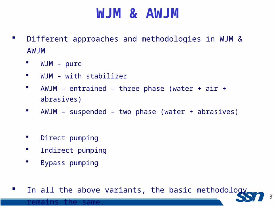
Different approaches and methodologies in WJM & AWJM
WJM – pure
WJM – with stabilizer
AWJM – entrained – three phase (water + air + abrasives)
AWJM – suspended – two phase (water + abrasives)
Direct pumping
Indirect pumping
Bypass pumping
In all the above variants, the basic methodology remains the same.
WJM & AWJM
4
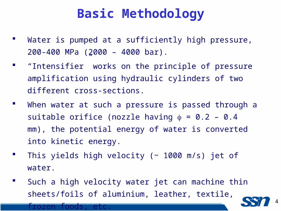
Water is pumped at a sufficiently high pressure, 200-400 MPa (2000 –
4000 bar).
“Intensifier” works on the principle of pressure amplification using
hydraulic cylinders of two different cross-sections.
When water at such a pressure is passed through a suitable orifice (nozzle
having = 0.2 – 0.4 mm), the potential energy of water is converted into
kinetic energy.
This yields high velocity (~ 1000 m/s) jet of water.
Such a high velocity water jet can machine thin sheets/foils of
aluminium, leather, textile, frozen foods, etc.
WJM – commercially pure water (tap water) is used for machining.
Basic Methodology
5
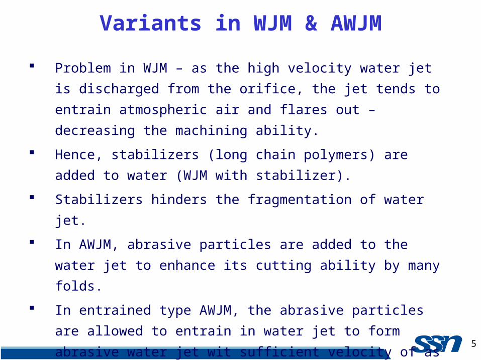
Problem in WJM – as the high velocity water jet is discharged from the
orifice, the jet tends to entrain atmospheric air and flares out – decreasing
the machining ability.
Hence, stabilizers (long chain polymers) are added to water (WJM with
stabilizer).
Stabilizers hinders the fragmentation of water jet.
In AWJM, abrasive particles are added to the water jet to enhance its
cutting ability by many folds.
In entrained type AWJM, the abrasive particles are allowed to entrain in
water jet to form abrasive water jet wit sufficient velocity of as high as
800 m/s.
Such high velocity abrasive jet can machine almost any material.
Variants in WJM & AWJM
6
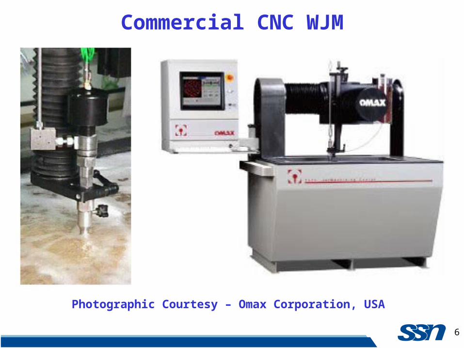
Commercial CNC WJM
Photographic Courtesy – Omax Corporation, USA
7
Paint removal
Cleaning
Cutting soft materials
Cutting frozen meat
Textile, Leather industry
Mass Immunization
Surgery
Peening
Pocket Milling
Drilling & Turning
Nuclear Plant Dismantling
WJM & AWJM - Applications

8
Steels & Non-ferrous alloys
Ti alloys, Ni- alloys
Polymers
Honeycombs
Metal Matrix Composite & Ceramic Matrix Composite
Concrete
Stone – Granite
Wood
Reinforced plastics
Metal Polymer Laminates
Glass Fibre Metal Laminates
WJM & AWJM - Materials
9
The cutting ability of WJM can be improved drastically by adding hard
and sharp abrasive particles into the water jet.
Thus, WJM is typically used to cut so called “softer” and “easy-to-
machine” materials like thin sheets and foils, non-ferrous metallic alloys,
wood, textiles, honeycomb, polymers, frozen meat, leather etc.
But, the domain of “harder” and “difficult-to-machine” materials like
thick plates of steels, aluminium and other commercial materials, metal
matrix and ceramic matrix composites, reinforced plastics, layered
composites, etc. are reserved for AWJM.
Other than cutting (machining) high pressure water jet also finds
application in paint removal, cleaning, surgery, peening to remove
residual stress etc.
Applications of WJM & AWJM
10
AWJM can as well be used besides cutting for pocket milling, turning,
drilling, etc.
One of the strategic areas where “robotic AWJM” is finding critical
application is dismantling of nuclear plants.
Applications – Contd.
11
Applications – Contd.
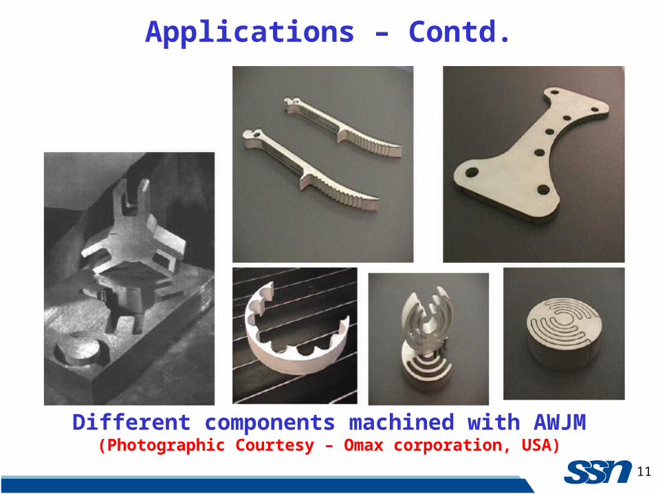
Different components machined with AWJM(Photographic Courtesy – Omax corporation, USA)
12
Extremely fast set-up and programming
Very little fixturing for most parts
Machine virtually any 2D shape on any material
Very low side forces during the machining
Almost no heat generated on the part
Can machine thick plates
WJM & AWJM - Advantages
13
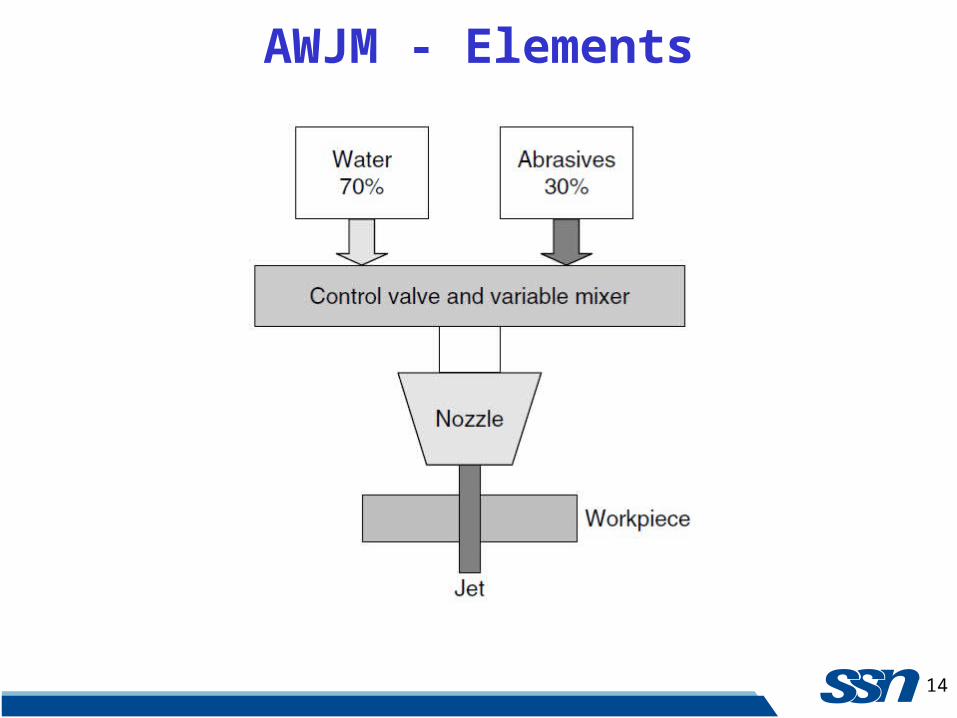
AWJM accelerates a jet of water (70 percent) and abrasive (30 percent)
from 4.2 bar up to a velocity of 30 m/s.
Silicon carbides, sand (SiO2), corundum, and glass beads of grain size 10
to 150 μm are often used as abrasive materials.
Using such a method, burrs of 0.35 mm height and 0.02 mm width left in
steel component after grinding are removed by the erosive effect of the
abrasives while water acts as an abrasive carrier.
The introduction of compressed air to the water jet enhances the
deburring action.
AWJM - Elements
14
AWJM - Elements
15
In AWJM, the water jet accelerates abrasive particles, not the water, to
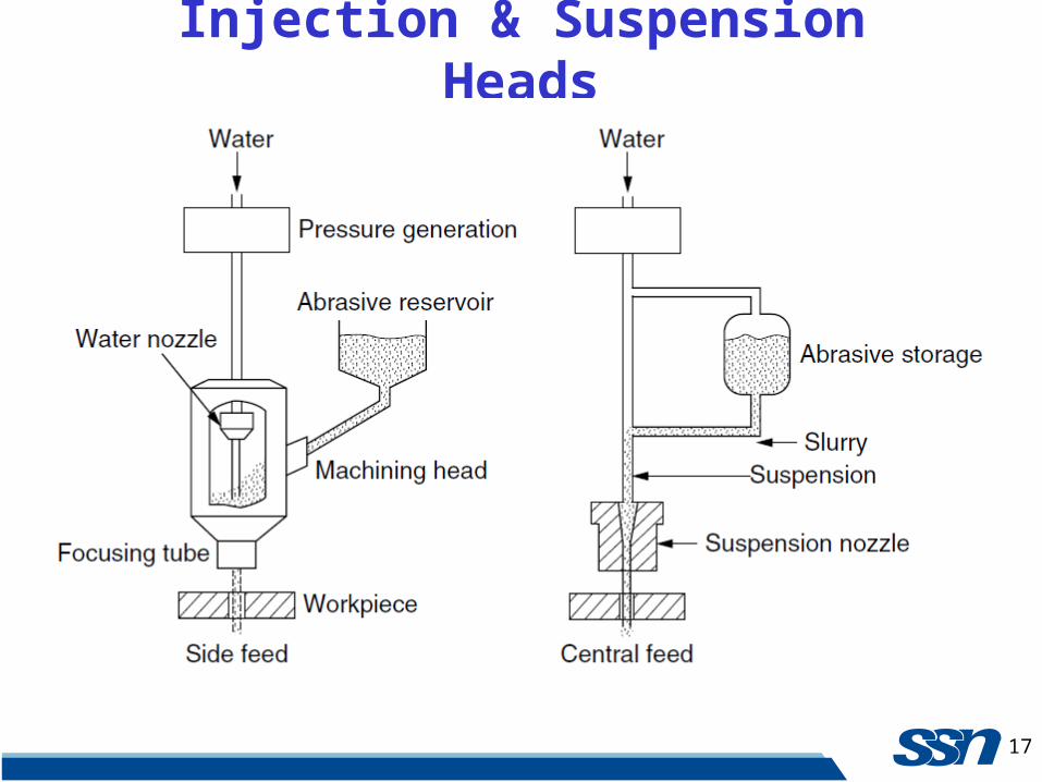
cause the material removal.
After the pure water jet is created, abrasives are added using either the
injection or suspension methods.
The important parameters of the abrasives are the material structure and
hardness, grain shape, size, and distribution.
The basic machining system of AWJM incorporates the following
Elements.
Machining System
Water delivery
Abrasive hopper and feeder
Intensifier
Filters
Mixing chamber
Cutting nozzles
Catcher

16
Schematic Setup of AWJM
17
Injection & Suspension Heads
18
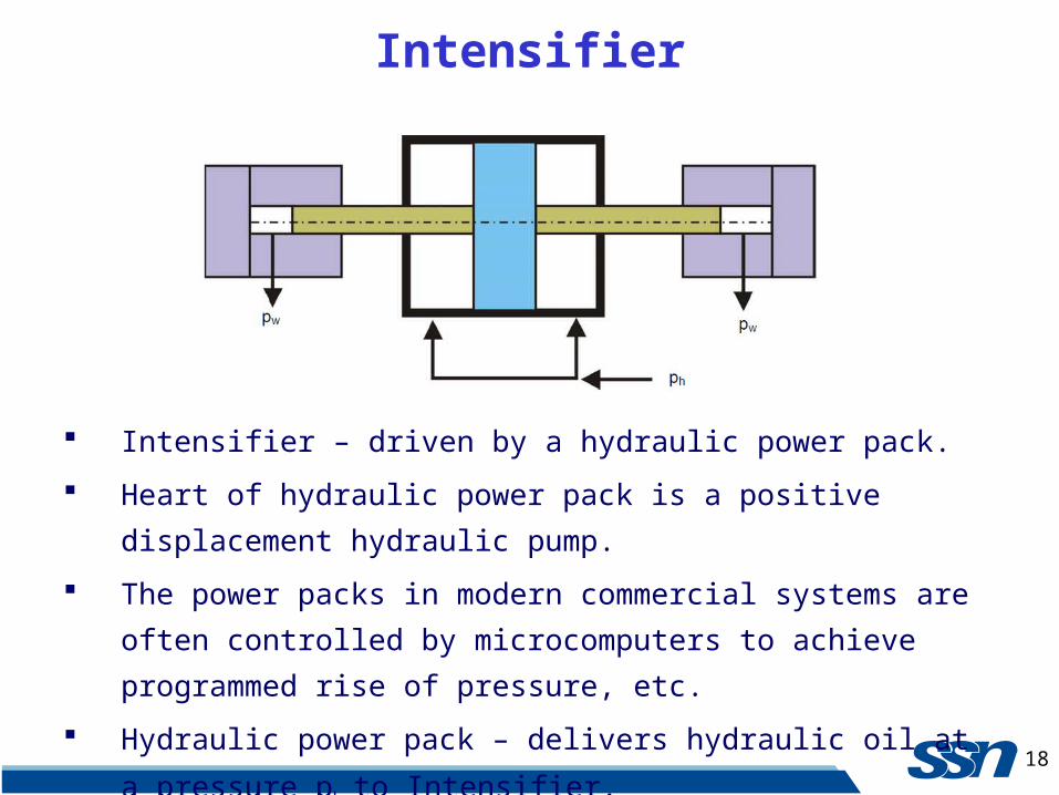
Intensifier
Intensifier – driven by a hydraulic power pack.
Heart of hydraulic power pack is a positive displacement hydraulic pump.
The power packs in modern commercial systems are often controlled by
microcomputers to achieve programmed rise of pressure, etc.
Hydraulic power pack – delivers hydraulic oil at a pressure ph to
Intensifier.
19
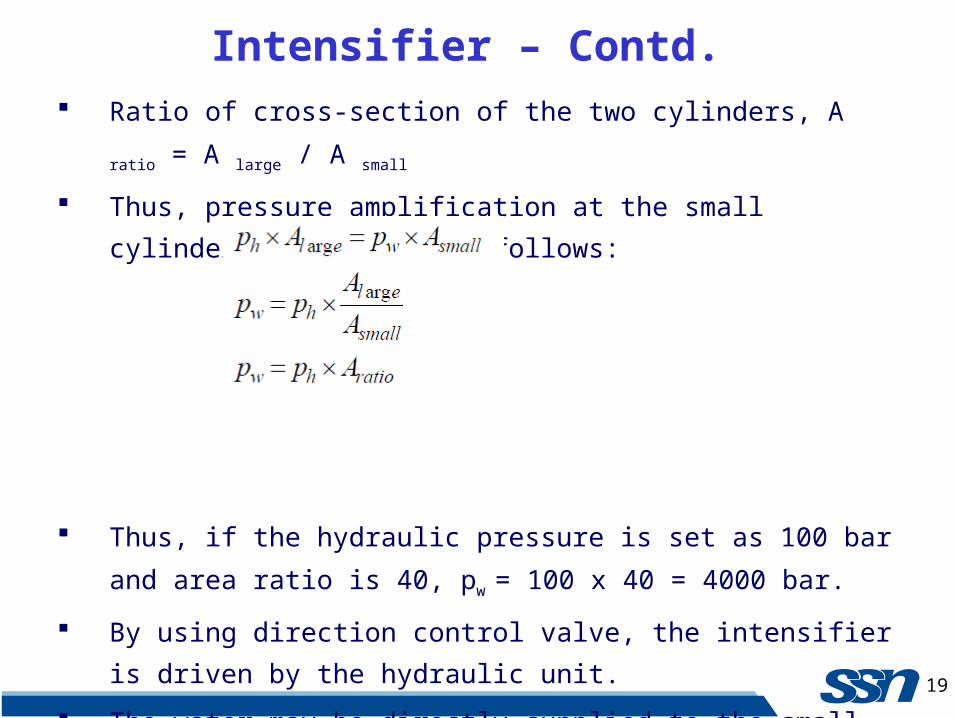
Intensifier – Contd. Ratio of cross-section of the two cylinders, A ratio = A large / A small
Thus, pressure amplification at the small cylinder takes place as follows:
Thus, if the hydraulic pressure is set as 100 bar and area ratio is 40, pw =
100 x 40 = 4000 bar.
By using direction control valve, the intensifier is driven by the hydraulic
unit.
The water may be directly supplied to the small cylinder of the
intensifier.
20
Intensifier – Contd. Or it may be supplied through a booster pump, which typically raises the
water pressure to 11 bar before the intensifier.
Sometimes water is softened or long chain polymers are added in
“additive unit”.
Thus, as the intensifier works, it delivers high pressure water.
As the larger piston changes direction within the intensifier, there would
be a drop in the delivery pressure.
To counter such drops, a thick cylinder is added to the delivery unit to
accommodate water at high pressure.
This is called an “accumulator” which acts like a “fly wheel” of an engine
and minimises fluctuation of water pressure.
21
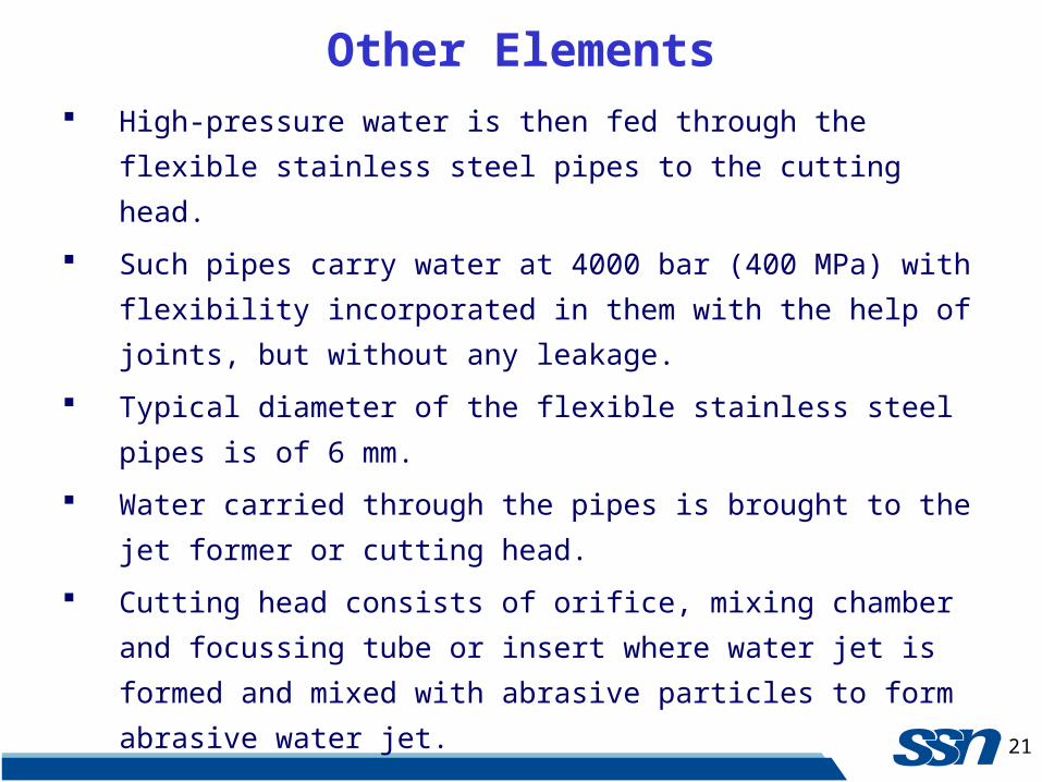
Other Elements High-pressure water is then fed through the flexible stainless steel pipes
to the cutting head.
Such pipes carry water at 4000 bar (400 MPa) with flexibility
incorporated in them with the help of joints, but without any leakage.
Typical diameter of the flexible stainless steel pipes is of 6 mm.
Water carried through the pipes is brought to the jet former or cutting
head.
Cutting head consists of orifice, mixing chamber and focussing tube or
insert where water jet is formed and mixed with abrasive particles to form
abrasive water jet.
22
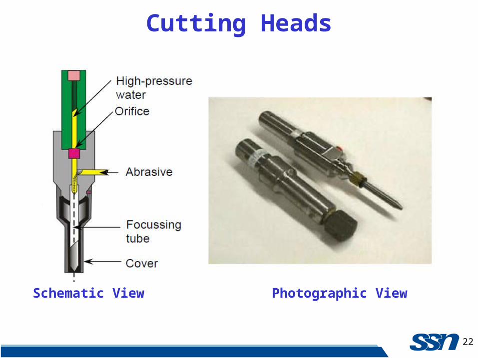
Cutting Heads
Schematic View Photographic View
23
Production of Water Jet The potential or pressure head of the water is converted into velocity
head by allowing the high-pressure water to pass through an orifice of
small diameter (0.2 – 0.4 mm).
The velocity of the water jet thus formed can be estimated, assuming no
losses as vwj = (2pw
/ ρw)1/2 using Bernoulli’s equation.
Where, pw and ρw
are pressure and density of water respectively.
The orifices are typically made of sapphire.
In commercial machines, the life of the sapphire orifice is typically
around 100 – 150 hours.
In WJM this high velocity water jet is used for the required application
where as in AWJM it is directed into the mixing chamber.
Typical mixing chamber - inner diameter 6 mm and a length of 10 mm.
24
Abrasive Water Jet As the high velocity water is issued from the orifice into the mixing
chamber, low pressure (vacuum) is created within the mixing chamber.
Metered abrasive particles are introduced into the mixing chamber
through a port.
The abrasive particles are metered using different techniques like
vibratory feeder or toothed belt feeder.
25
Mixing Chamber Mixing means gradual entrainment of abrasive particles within water jet.
Finally the abrasive water jet comes out of focussing tube or nozzle.
During mixing, the abrasive particles are gradually accelerated due to
transfer of momentum from water phase to abrasive phase.
When the jet finally leaves the focussing tube, both phases, water and
abrasive, are assumed to be at same velocity.
Mixing chamber is immediately followed by focussing tube or inserts.
Focussing tube is generally made of tungsten carbide (powder metallurgy
product).
Typical dimension - inner diameter of 0.8 to 1.6 mm and a length of 50 to
80 mm.
Tungsten carbide is used for its abrasive resistance.
26
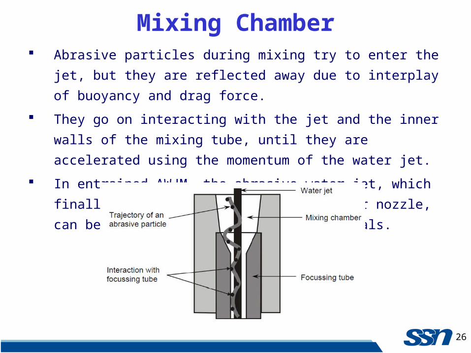
Mixing Chamber Abrasive particles during mixing try to enter the jet, but they are reflected
away due to interplay of buoyancy and drag force.
They go on interacting with the jet and the inner walls of the mixing tube,
until they are accelerated using the momentum of the water jet.
In entrained AWJM, the abrasive water jet, which finally comes from the
focussing tube or nozzle, can be used to machine different materials.
27
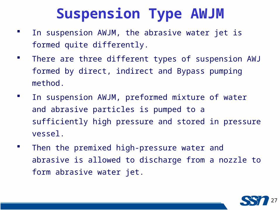
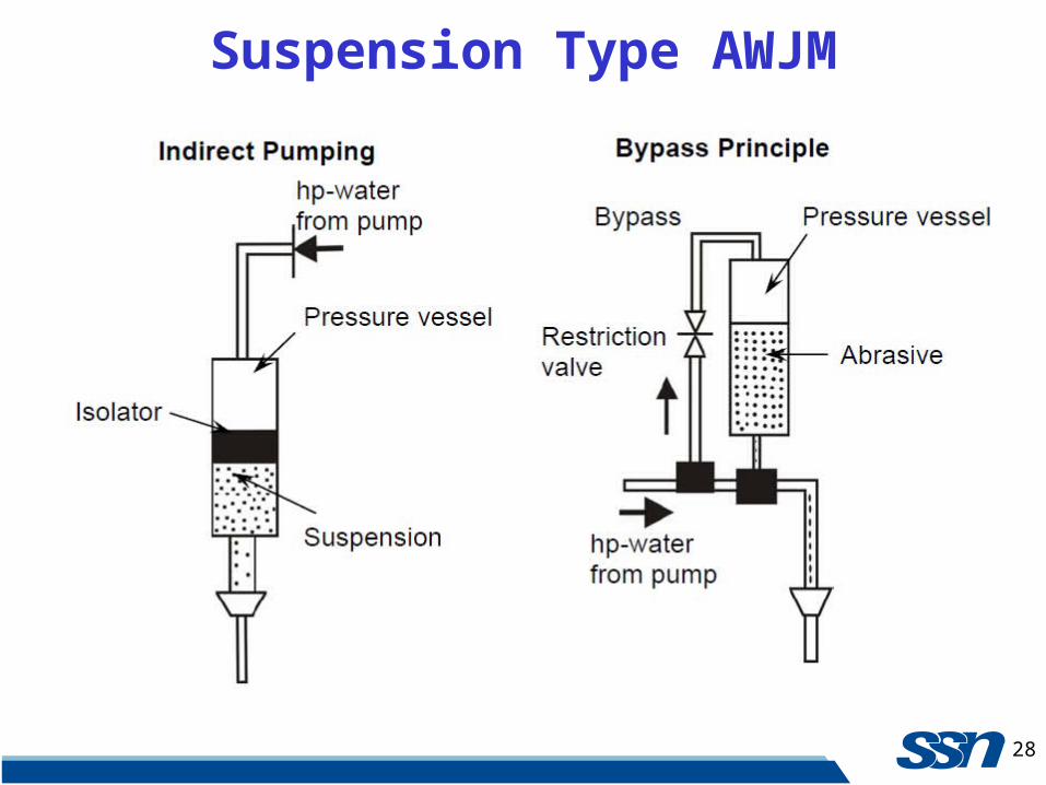
Suspension Type AWJM In suspension AWJM, the abrasive water jet is formed quite differently.
There are three different types of suspension AWJ formed by direct,
indirect and Bypass pumping method.
In suspension AWJM, preformed mixture of water and abrasive particles
is pumped to a sufficiently high pressure and stored in pressure vessel.
Then the premixed high-pressure water and abrasive is allowed to
discharge from a nozzle to form abrasive water jet.
28
Suspension Type AWJM
29
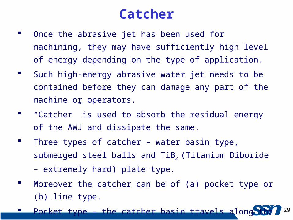
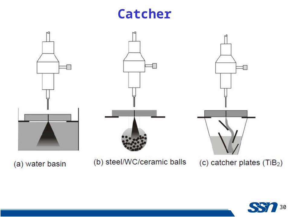
Catcher Once the abrasive jet has been used for machining, they may have
sufficiently high level of energy depending on the type of application.
Such high-energy abrasive water jet needs to be contained before they
can damage any part of the machine or operators.
“Catcher” is used to absorb the residual energy of the AWJ and dissipate
the same.
Three types of catcher – water basin type, submerged steel balls and TiB2
(Titanium Diboride – extremely hard) plate type.
Moreover the catcher can be of (a) pocket type or (b) line type.
Pocket type – the catcher basin travels along the jet (along x and y axes).
Line type – the catcher basin travels along one axis and its length covers
the entire width of the other axis of the CNC table.
30
Catcher
31
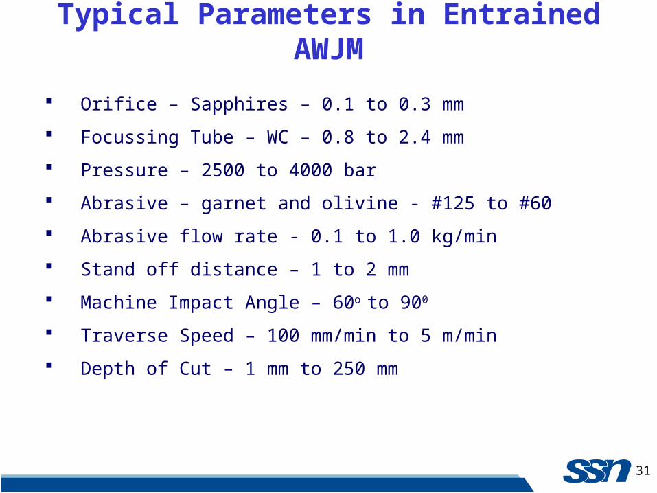
Typical Parameters in Entrained AWJM
Orifice – Sapphires – 0.1 to 0.3 mm
Focussing Tube – WC – 0.8 to 2.4 mm
Pressure – 2500 to 4000 bar
Abrasive – garnet and olivine - #125 to #60
Abrasive flow rate - 0.1 to 1.0 kg/min
Stand off distance – 1 to 2 mm
Machine Impact Angle – 60o to 900
Traverse Speed – 100 mm/min to 5 m/min
Depth of Cut – 1 mm to 250 mm
32
Material Removal in AWJM
Mechanism of material removal in WJM or AWJM is rather complex.
In AWJ machining of ductile materials, material is mainly removed by
low angle impact of abrasive particles.
Further at higher angle of impact, the material removal involves plastic
failure of the material at the sight of impact.
In AWJ machining of brittle materials, material would be removed due to
crack initiation and propagation because of brittle failure of the material.
In water jet machining, the material removal rate may be assumed to be
proportional to the power of the water jet.
33
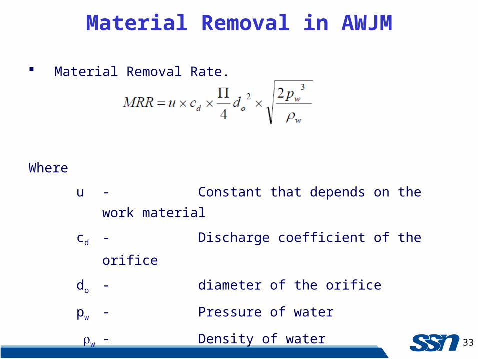
Material Removal in AWJM
Material Removal Rate.
Where
u - Constant that depends on the work material
cd - Discharge coefficient of the orifice
do - diameter of the orifice
pw - Pressure of water
w - Density of water
34
Material Removal in AWJM
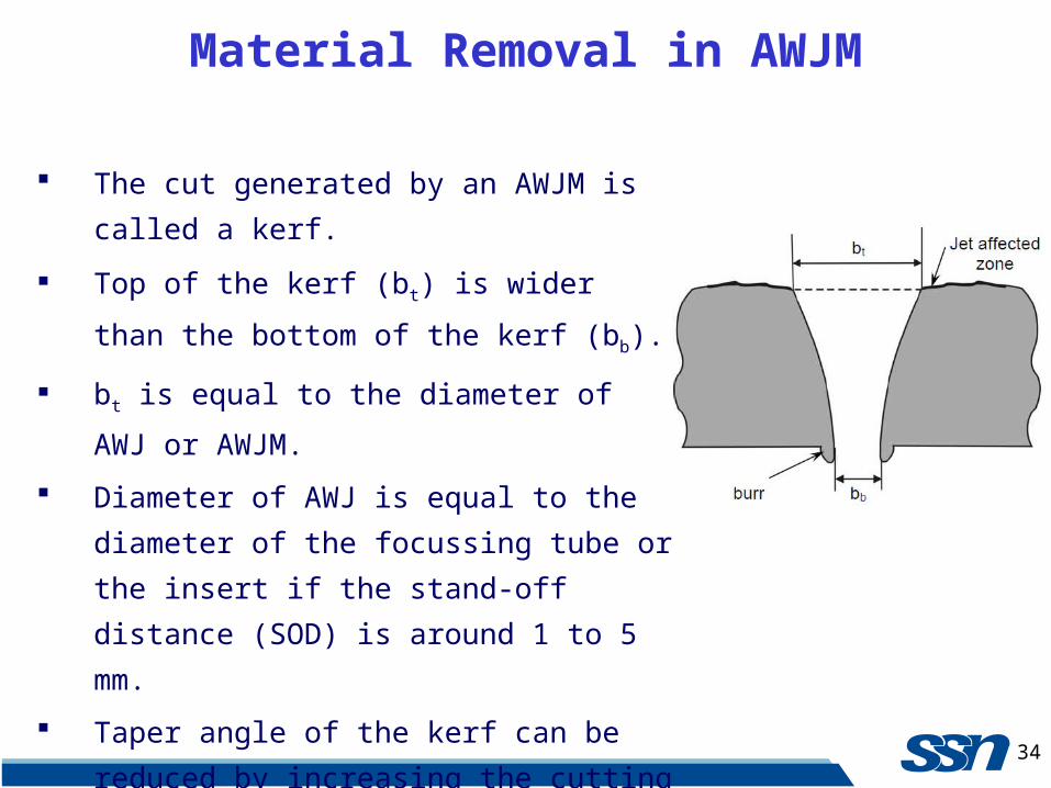
The cut generated by an AWJM is called a kerf.
Top of the kerf (bt) is wider than the bottom of
the kerf (bb).
bt is equal to the diameter of AWJ or AWJM.
Diameter of AWJ is equal to the diameter of the
focussing tube or the insert if the stand-off
distance (SOD) is around 1 to 5 mm.
Taper angle of the kerf can be reduced by
increasing the cutting ability of the AWJ.
35
Material Removal in AWJM
36
Material Removal in AWJM
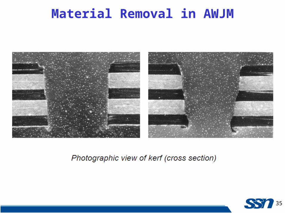
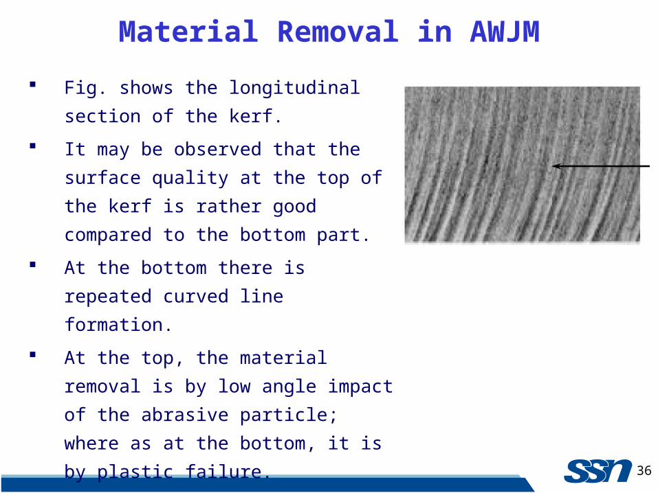
Fig. shows the longitudinal section of the
kerf.
It may be observed that the surface quality
at the top of the kerf is rather good
compared to the bottom part.
At the bottom there is repeated curved line
formation.
At the top, the material removal is by low
angle impact of the abrasive particle; where
as at the bottom, it is by plastic failure.
Striation formation occurs due to repeated
plastic failure.
37
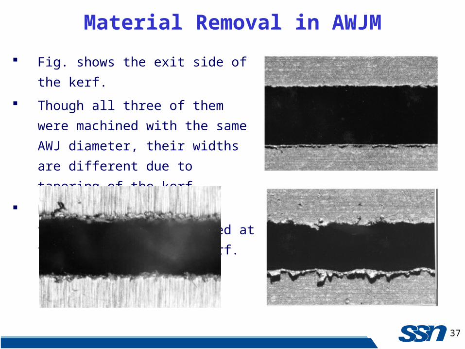
Material Removal in AWJM
Fig. shows the exit side of the kerf.
Though all three of them were machined
with the same AWJ diameter, their
widths are different due to tapering of the
kerf.
Further, severe burr formation can be
observed at the exit side of the kerf.

38
Material Removal in AWJM
Thus, in WJM and AWJM the following are the important product quality
parameters.
Striation formation.
Surface finish of the kerf.
Tapering of the kerf.
Burr formation on the exit side of the kerf.
39
Process variables
Pressure
Nozzle diameter
Standoff distance
Abrasive type and grit number
Workpiece feed rate
An abrasive water jet cuts through 356.6 mm thick slabs of concrete or
76.6-mm-thick tool steel plates at 38 mm/min in a single pass.
Surface roughness ranges between 3.8 and 6.4 μm.
Tolerance - 0.13 mm.
Repeatability - 0.04 mm.
Straightness – 0.05 mm per axis length.
Process Capabilities
40
Foundry sands are frequently used as abrasives.
However, garnet (the most common abrasive material) is 30 percent more
effective than sand.
Cutting rate during machining of glass – 16.4 mm3/min.
This is 4 to 6 times higher for metals.
Surface roughness depends on the workpiece material, grit size, and type
of abrasives.
A material with a high removal rate produces large surface roughness.
Process Capabilities – Contd.
41
Fine grains are used for machining soft metals to achieve better
roughness
The decrease in surface roughness by using smaller grain size is related to
the reduced depth of cut and the undeformed chip cross section.
A carrier liquid consisting of water with anticorrosive additives has
higher density and contributes to higher acceleration of the grains.
This results in higher grain speed and increased metal removal rate.
Moreover, the carrier liquid spreads over the surface filling its cavities
and forming a film that impedes the striking action of the grains.
Therefore, peaks in the surface irregularities are the first to be affected
and the surface quality improves.
Process Capabilities – Contd.
42
Kaczmarek (1976) showed that the use of water air jet permits one to
obtain, on average, a roughness number higher by one, as compared with
the effect of an air jet.
In high-speed WJM of Inconel, Hashish (1992) concluded that the
roughness increases at higher feed rates as well as at lower slurry flow
rates.
Published Results
43
Advanced water jet and AWJ machines are now available where the
computer loads a CAD drawing from another system.
The computer determines the starting and end points and the sequence of
operations.
The operator then enters the material type and tool offset data.
The computer determines the feed rate and performs cutting.
Other machining systems operate with a modem and CAD/CAM
capabilities that permits transfer from CATIA, AUTOCAD, IGES, and
DXF formats.
The computer runs a program that determines, in seconds, how to
minimize the waste when cutting blocks or plates.
Computer Controlled AWJM