Embed Size (px)
Citation preview

DKPP 32.50.13-35.00
2
TABLE OF CONTENTS
1. APPLICATION ........................................................................................................................ 3
2. SPECIFICATION ..................................................................................................................... 4
3. PACKAGE CONTENTS .......................................................................................................... 5
4. ARRANGEMENT AND PRINCIPLES OF OPERATION....................................................... 6
5. SECURITY PRECAUTIONS ................................................................................................... 9
6. LABELLING AND SYMBOLS .............................................................................................. 10
7. DEVICE ASSEMBLY ............................................................................................................ 11
8. OPERATION PROCEDURE ................................................................................................. 14
9. TECHNICAL MAINTENANCE ............................................................................................ 15
10. POSSIBLE MALFUNCTIONS AND WAYS OF THEIR ELIMINATION .......................... 16
11. ACCEPTANCE CERTIFICATE .......................................................................................... 18
12. MANUFACTURER’S WARRANTY .................................................................................... 19
APPENDIX А ............................................................................................................................. 20
ATTENTION! Read this manual thoroughly before operating the device.
3
Manufacturer:
«SEC «Scaner» Ltd.
122/1 Smelianska str., 18019,
Cherkassy, Ukraine
E-mail: [email protected] http://www.scaner.ck.ua
Phone/fax: +38(0472) 55-27-35(34)
Toll-free calls in Ukraine from landline phones.
Phone: 0-800-30-10-19
EC-Representative:
«Pharma Complex Solutions» Ltd.
200C/344 Górczewska str., 01-460,
Warsaw, Poland
E-mail: [email protected] http://www.pcsolutions.pl
Phone/fax: +48227222305
1. APPLICATION
Colposcope МК - 200 (hereinafter referred to as the colposcope) is a medical device intended for
stereoscopic examination of vagina, neck of uterus and the lower third of cervical canal with optic magnification
using a non-invasive method in the process of gynecological and oncogynecological analysis.
Scope of use – gynecology, gynecological oncology.
The colposcope is necessary in the following cases:
- Examination the state of epithelium in the neck of uterus, vagina and vulva with optical magnification;
- Search for localization and borders of the lesion focus;
- Differentiation of benign formation from suspicious malformation;
- Targeted sampling of cytological swabs and biopsy with view of significant growth of their
information value;
- Carrying put medical treatment under optical control (operative CS);
- Control of the treatment results;
- Evaluation of the process dynamics in case of a conservative way of treatment.
The video system is intended for online studying a coloured image of the area under investigation on a
computer monitorля or, if necessary, its simultaneous transmitting to the second monitor at the spot of the
patient’s examination. The image on the computer screen coincides with the one seen through the eyepieces of
the colposcope completely. The video system allows making instant snaps with high resolution with the help of
a button that is situated on the colposcope.
The video system does not impairs operating or optical characteristics of the colposcope.
ATTENTION! On request the colposcope is supplied with the video system, or the video system
can be supplier later.
4
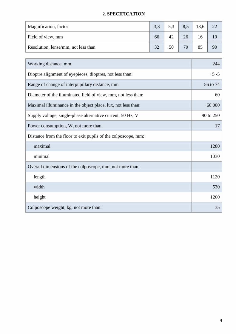
2. SPECIFICATION
Magnification, factor 3,3 5,3 8,5 13,6 22
Field of view, mm 66 42 26 16 10
Resolution, lense/mm, not less than 32 50 70 85 90
Working distance, mm 244
Dioptre alignment of eyepieces, dioptres, not less than: +5 -5
Range of change of interpupillary distance, mm 56 to 74
Diameter of the illuminated field of view, mm, not less than: 60
Maximal illuminance in the object place, lux, not less than: 60 000
Supply voltage, single-phase alternative current, 50 Hz, V 90 to 250
Power consumption, W, not more than: 17
Distance from the floor to exit pupils of the colposcope, mm:
maximal 1280
minimal 1030
Overall dimensions of the colposcope, mm, not more than:
length 1120
width 530
height 1260
Colposcope weight, kg, not more than: 35
5
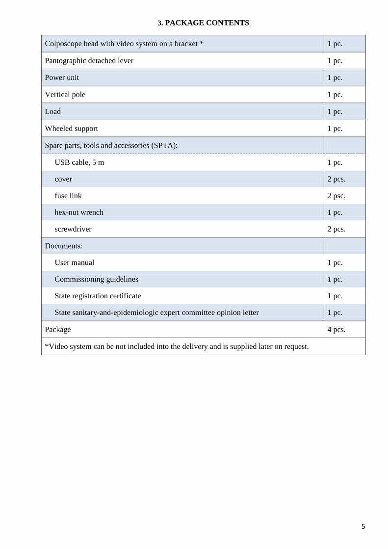
3. PACKAGE CONTENTS
Colposcope head with video system on a bracket * 1 pc.
Pantographic detached lever 1 pc.
Power unit 1 pc.
Vertical pole 1 pc.
Load 1 pc.
Wheeled support 1 pc.
Spare parts, tools and accessories (SPTA):
USB cable, 5 m 1 pc.
cover 2 pcs.
fuse link 2 psc.
hex-nut wrench 1 pc.
screwdriver 2 pcs.
Documents:
User manual 1 pc.
Commissioning guidelines 1 pc.
State registration certificate 1 pc.
State sanitary-and-epidemiologic expert committee opinion letter 1 pc.
Package 4 pcs.
*Video system can be not included into the delivery and is supplied later on request.
6
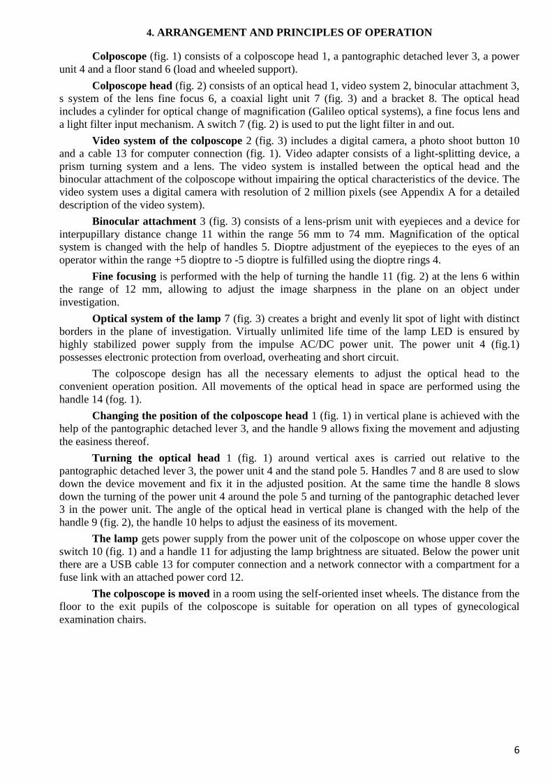
4. ARRANGEMENT AND PRINCIPLES OF OPERATION
Colposcope (fig. 1) consists of a colposcope head 1, a pantographic detached lever 3, a power
unit 4 and a floor stand 6 (load and wheeled support).
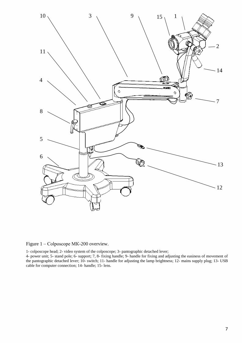
Colposcope head (fig. 2) consists of an optical head 1, video system 2, binocular attachment 3,
s system of the lens fine focus 6, a coaxial light unit 7 (fig. 3) and a bracket 8. The optical head
includes a cylinder for optical change of magnification (Galileo optical systems), a fine focus lens and
a light filter input mechanism. A switch 7 (fig. 2) is used to put the light filter in and out.
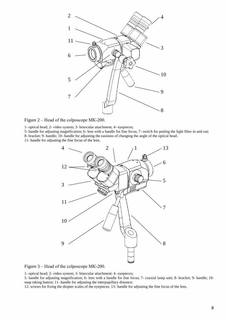
Video system of the colposcope 2 (fig. 3) includes a digital camera, a photo shoot button 10
and a cable 13 for computer connection (fig. 1). Video adapter consists of a light-splitting device, a
prism turning system and a lens. The video system is installed between the optical head and the
binocular attachment of the colposcope without impairing the optical characteristics of the device. The
video system uses a digital camera with resolution of 2 million pixels (see Appendix A for a detailed
description of the video system).
Binocular attachment 3 (fig. 3) consists of a lens-prism unit with eyepieces and a device for
interpupillary distance change 11 within the range 56 mm to 74 mm. Magnification of the optical
system is changed with the help of handles 5. Dioptre adjustment of the eyepieces to the eyes of an
operator within the range +5 dioptre to -5 dioptre is fulfilled using the dioptre rings 4.
Fine focusing is performed with the help of turning the handle 11 (fig. 2) at the lens 6 within
the range of 12 mm, allowing to adjust the image sharpness in the plane on an object under
investigation.
Optical system of the lamp 7 (fig. 3) creates a bright and evenly lit spot of light with distinct
borders in the plane of investigation. Virtually unlimited life time of the lamp LED is ensured by
highly stabilized power supply from the impulse AC/DC power unit. The power unit 4 (fig.1)
possesses electronic protection from overload, overheating and short circuit.
The colposcope design has all the necessary elements to adjust the optical head to the
convenient operation position. All movements of the optical head in space are performed using the
handle 14 (fog. 1).
Changing the position of the colposcope head 1 (fig. 1) in vertical plane is achieved with the
help of the pantographic detached lever 3, and the handle 9 allows fixing the movement and adjusting
the easiness thereof.
Turning the optical head 1 (fig. 1) around vertical axes is carried out relative to the
pantographic detached lever 3, the power unit 4 and the stand pole 5. Handles 7 and 8 are used to slow
down the device movement and fix it in the adjusted position. At the same time the handle 8 slows
down the turning of the power unit 4 around the pole 5 and turning of the pantographic detached lever
3 in the power unit. The angle of the optical head in vertical plane is changed with the help of the
handle 9 (fig. 2), the handle 10 helps to adjust the easiness of its movement.
The lamp gets power supply from the power unit of the colposcope on whose upper cover the
switch 10 (fig. 1) and a handle 11 for adjusting the lamp brightness are situated. Below the power unit
there are a USB cable 13 for computer connection and a network connector with a compartment for a
fuse link with an attached power cord 12.
The colposcope is moved in a room using the self-oriented inset wheels. The distance from the
floor to the exit pupils of the colposcope is suitable for operation on all types of gynecological
examination chairs.
7
Figure 1 – Colposcope МК-200 overview.
1- colposcope head; 2- video system of the colposcope; 3- pantographic detached lever;
4- power unit; 5- stand pole; 6- support; 7, 8- fixing handle; 9- handle for fixing and adjusting the easiness of movement of
the pantographic detached lever; 10- switch; 11- handle for adjusting the lamp brightness; 12- mains supply plug; 13- USB
cable for computer connection; 14- handle; 15- lens.
12
13
7
2
1 3
14
10
11
4
8
5
6
9 15
8
Figure 2 – Head of the colposcope МК-200.
1- optical head; 2- video system; 3- binocular attachment; 4- eyepieces;
5- handle for adjusting magnification; 6- lens with a handle for fine focus; 7- switch for putting the light filter in and out;
8- bracket; 9- handle; 10- handle for adjusting the easiness of changing the angle of the optical head.
11- handle for adjusting the fine focus of the lens.
Figure 3 – Head of the colposcope МК-200.
1- optical head; 2- video system; 3- binocular attachment; 4- eyepieces;
5- handle for adjusting magnification; 6- lens with a handle for fine focus; 7- coaxial lamp unit; 8- bracket; 9- handle; 10-
snap taking button; 11- handle for adjusting the interpupillary distance;
12- screws for fixing the diopter scales of the eyepieces. 13- handle for adjusting the fine focus of the lens.
8
9
3
4
6
7
10
2
8 9
7
5
6
2 4
3
10
1
5
1
11
12
11
13
9
5. SECURITY PRECAUTIONS
Based on their operation the colposcope and its video system belong to Boreal Climate 4.2.
climatic modification according to the GOST State Standard 15150 and are intended for operation at
ambient temperatures in the range +10°C to +40°C, relative humidity 30% to 75% and atmospheric
pressure 700 GPa to 1060 GPa.
Based on the level of its potential risk for the use in medical practice the colposcope МК-200
belongs to Class I according to the DSTU State Standard 4388 (Class I, Medical Device Directive
93/42/EEC).
Based on the type of electric shock protection the colposcope belongs to Class II protection,
type of protection ВF according to the DSTU State Standard 3798 (IEC 601-1). The colposcope lamp
is connected to the mains of single-phase alternative current with frequency 50 Hz and voltage 220V
using the power unit cord with a wall plug at its end.
The colposcope has no open contacts under voltage and is safe in its operation.
The electrical part of the colposcope must be repaired only by specially trained staff
authorized to work with electrical voltage up to 1000 V as long as they observe the safety standards for
maintenance and repairs of such equipment.
ATTENTION! It is prohibited to connect the power unit to the mains if the cover of the
unit is open. Before replacing a fuse the colposcope must be disconnected from the mains.
10
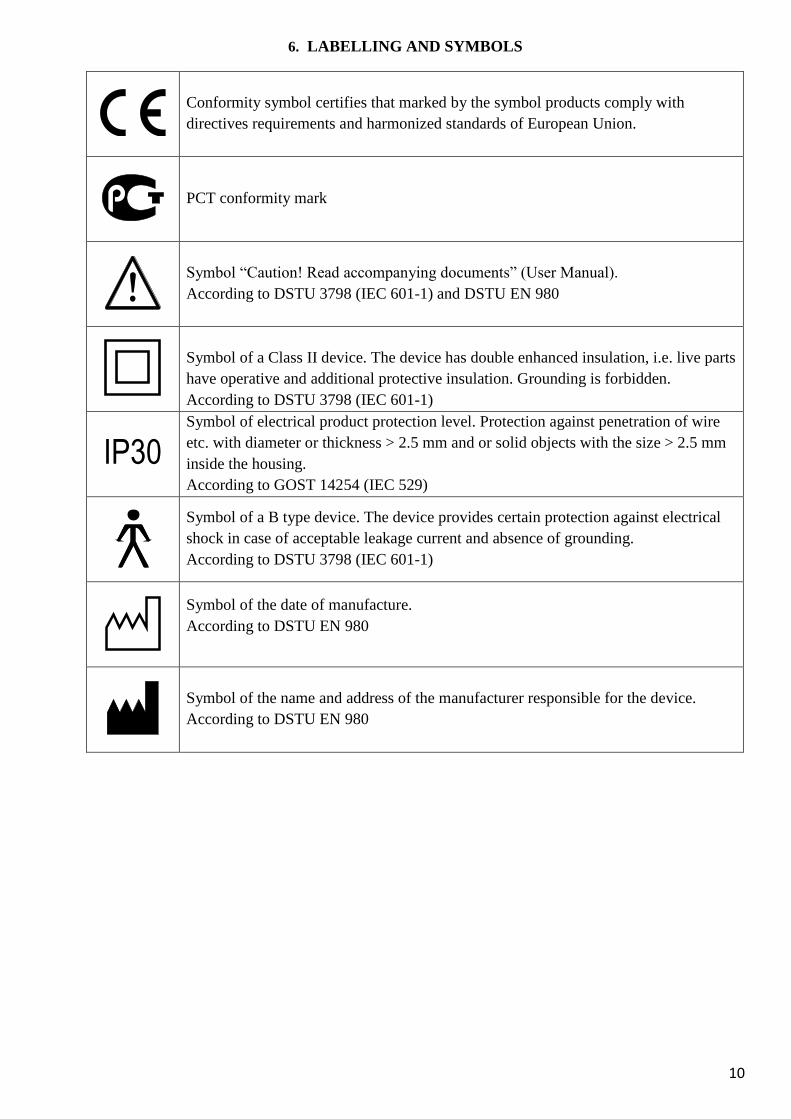
6. LABELLING AND SYMBOLS
Conformity symbol certifies that marked by the symbol products comply with
directives requirements and harmonized standards of European Union.
PCT conformity mark
Symbol “Caution! Read accompanying documents” (User Manual).
According to DSTU 3798 (IEC 601-1) and DSTU EN 980
Symbol of a Class II device. The device has double enhanced insulation, i.e. live parts
have operative and additional protective insulation. Grounding is forbidden.
According to DSTU 3798 (IEC 601-1)
IP30 Symbol of electrical product protection level. Protection against penetration of wire
etc. with diameter or thickness > 2.5 mm and or solid objects with the size > 2.5 mm
inside the housing.
According to GOST 14254 (IEC 529)
Symbol of a B type device. The device provides certain protection against electrical
shock in case of acceptable leakage current and absence of grounding.
According to DSTU 3798 (IEC 601-1)
Symbol of the date of manufacture.
According to DSTU EN 980
Symbol of the name and address of the manufacturer responsible for the device.
According to DSTU EN 980
11
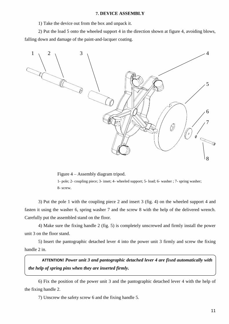
7. DEVICE ASSEMBLY
1) Take the device out from the box and unpack it.
2) Put the load 5 onto the wheeled support 4 in the direction shown at figure 4, avoiding blows,
falling down and damage of the paint-and-lacquer coating.
Figure 4 – Assembly diagram tripod.
1- pole; 2- coupling piece; 3- inset; 4- wheeled support; 5- load; 6- washer ; 7- spring washer;
8- screw.
3) Put the pole 1 with the coupling piece 2 and insert 3 (fig. 4) on the wheeled support 4 and
fasten it using the washer 6, spring washer 7 and the screw 8 with the help of the delivered wrench.
Carefully put the assembled stand on the floor.
4) Make sure the fixing handle 2 (fig. 5) is completely unscrewed and firmly install the power
unit 3 on the floor stand.
5) Insert the pantographic detached lever 4 into the power unit 3 firmly and screw the fixing
handle 2 in.
6) Fix the position of the power unit 3 and the pantographic detached lever 4 with the help of
the fixing handle 2.
7) Unscrew the safety screw 6 and the fixing handle 5.
ATTENTION! Power unit 3 and pantographic detached lever 4 are fixed automatically with
the help of spring pins when they are inserted firmly.
6
4 1 2
7
8
5
3
12
8) In turn, pull the cable for connection the video camera 11(if supplied with video system) and
illuminator 10 into the pantograph lever port 4.
9) Firmly insert the bracket axis of the colposcope head 9 into the opening of the pantographic
detached lever 4.
10) Tighten the safety screw 6 and the fixing handle 5.
11) Unscrew the screws 7 (2 pieces) and remove the cable housing 8.
12) Put the USB cable for video camera connection 11 and the lamp connection cable 10 into
the cable housing 8, fix it on the pantographic detached lever 4 with the help of the screws 7.
13) Insert the header of the lamp connection cable 10 into the appropriate socket on the power
unit 3 until its clicking position.
14) Firmly insert the USB cable header for connection of the digital camera 11 into the
appropriate socket on the power unit 3.
15) Connect the power cord 12 to the power unit 3 and fix it with a special clip to prevent its
spontaneous disconnection.
16) The colposcope is ready for operation.
ATTENTION! After insertion the cables on the side of the colposcope head and the
power unit must be long enough to allow moving the colposcope in any direction without
obstacles.
13
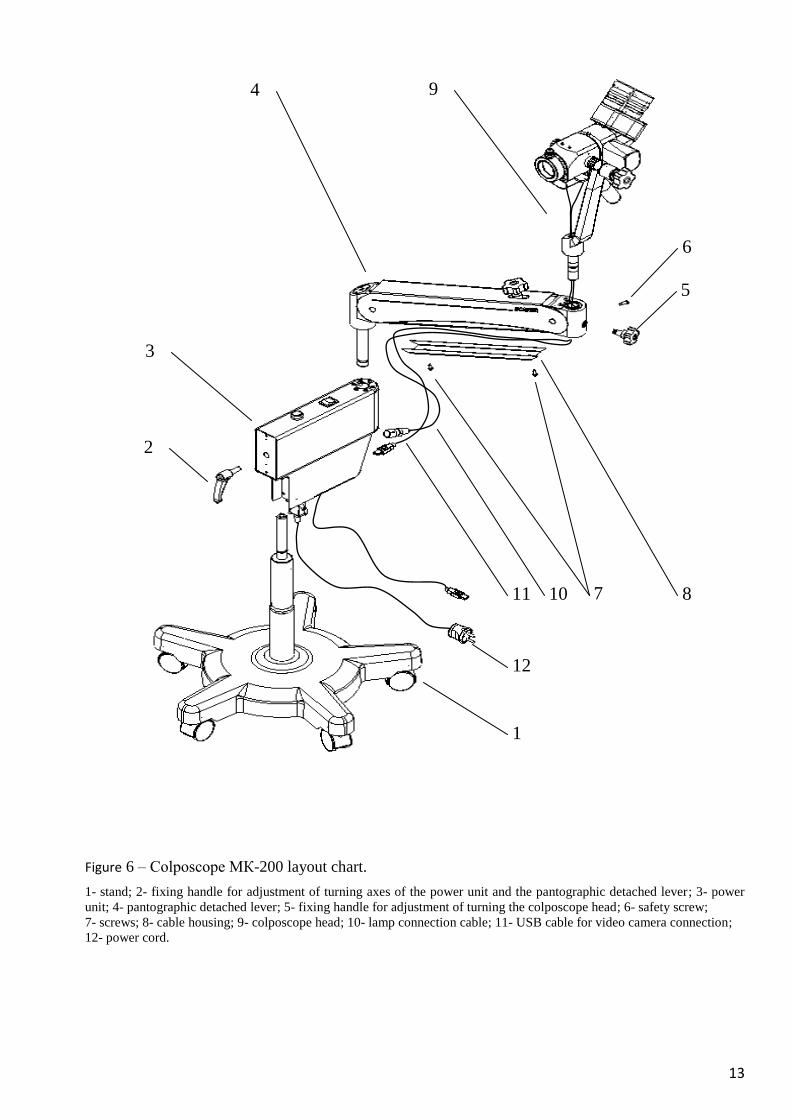
Figure 6 – Colposcope МК-200 layout chart.
1- stand; 2- fixing handle for adjustment of turning axes of the power unit and the pantographic detached lever; 3- power
unit; 4- pantographic detached lever; 5- fixing handle for adjustment of turning the colposcope head; 6- safety screw;
7- screws; 8- cable housing; 9- colposcope head; 10- lamp connection cable; 11- USB cable for video camera connection;
12- power cord.
9 4
3
2
6
11
12
1
5
10 8 7
14
8. OPERATION PROCEDURE
1) Put the colposcope in the position suitable for operation.
2) Connect the power cord 12 (fig. 1) to the mains.
3) Switch on the colposcope lamp using the switch 10.
4) Turn the eyepieces 4 (fig. 2) around their axes to adjust them according to the dioptre
characteristic of the operator’s eyes on the basis of the dioptre scale. Fix the position of the eyepieces
with the help of the fixing screws 12 (fig. 3).
5) Put the object in front of the colposcope lens.
6) Put the colposcope head in the position suitable for operation using the handle 9 (fig. 2) and
slowing down the movement or fixing the position with the help of the handles 10 (fig. 2), 7 and 8
(fig. 1).
7) Adjust the magnification of the colposcope turning the handles 5 (fig. 3).
8) Adjust the illuminance of the object using the adjustment handle 11 (fig. 1).
9) Make the image of the object in the eyepieces look sharp, for this purpose move the
colposcope head using the handle 9 (fig. 3) and turning the fine focus handle 13 of the lens 6.
10) Put the eyepieces in the need position according to the distance between the eyes of the
operator with the help of the handle 11.
11) If necessary, turn on (turn off) the light filter using the switch 7 (fig. 2).
ATTENTION! To prevent defocusing of the colposcope during adjustment of
magnification the initial focusing at the object must be done at the highest value of
magnification.
15
9. TECHNICAL MAINTENANCE
Its technical maintenance must be carried out each time while preparing the colposcope for
operation in order to ensure its reliability.
During technical maintenance of the colposcope the operators should do the following:
1) Examine the device to make sure the external optical elements are clean;
2) Clean the external surfaces of the optical elements from dust and deposition using a wad of
cotton wool damped with spirits;
3) Check the operability of the power cord and plug (there must be no ruptures on the cord
surface through which the cable conductors could be seen; the cord must be firmly inserted into the
plug and not allow twisting; plug pins should not be bent; there must not be any cracks or shearing on
the plug surface);
4) After operation rub the external surfaces of the colposcope with a well-squeezed cotton wad
damped in 3% hydrogen peroxide solution according to the GOST 177-77 with addition of 0.5%
detergent of “Lotus” type.
5) In order to prevent dust deposition on the optical surfaces cover the colposcope head with a
plastic bag.
16
10. POSSIBLE MALFUNCTIONS AND WAYS OF THEIR ELIMINATION
Sings of malfunctioning Possible explanation Way of elimination
“Mains” indicator of the
mains switch is not on.
No voltage in the mains
supply 220 V, 50 Hz
Check voltage in the mains supply,
220 V, 50 Hz
The fuse link (fuse) is out of
order
Replace the fuse link (fuse) on the
lower panel of the power unit.
No contact in the mains
connection of the power unit
or damaged power cord
Disconnect the mains cable from the
power unit and connect it again after
having made sure the plug is firmly
connected and fixed.
The mains switch of the
colposcope power unit is out
of order
Apply to the technical service.
The lamp LED is not on, but
“Mains” indicator of the
mains switch is on.
No contact in the cable
header or damaged power
cord of the lamp
Disconnect the lamp cable from the
power unit and the optical head of
the colposcope, make sure the cable
is not mechanically damaged, and
connect it again in such a way that
pins are firmly connected and fixed
in appropriate sockets.
The lamp LED or the power
unit of the colposcope is out
of order
Apply to the technical service
The object image is not sharp
though all the rules of
focusing control are observed.
The external surfaces of the
optical elements are dirty.
Clean the external surfaces of the
optical elements with rectified ethyl
alcohol.
17
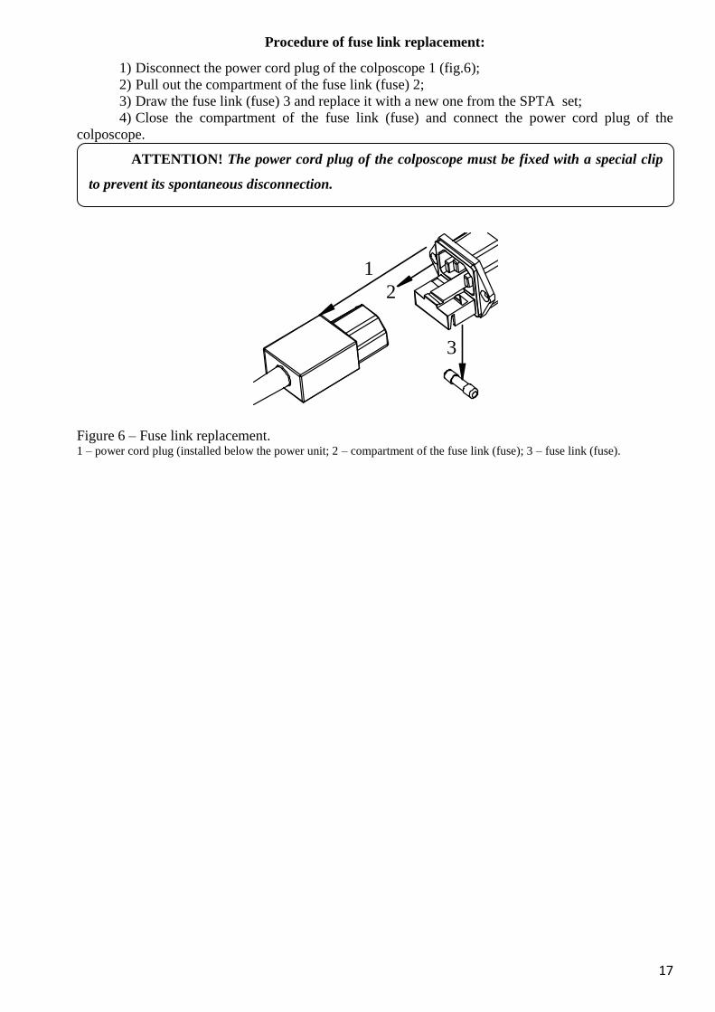
Procedure of fuse link replacement:
1) Disconnect the power cord plug of the colposcope 1 (fig.6);
2) Pull out the compartment of the fuse link (fuse) 2;
3) Draw the fuse link (fuse) 3 and replace it with a new one from the SPTA set;
4) Close the compartment of the fuse link (fuse) and connect the power cord plug of the
colposcope.
Figure 6 – Fuse link replacement. 1 – power cord plug (installed below the power unit; 2 – compartment of the fuse link (fuse); 3 – fuse link (fuse).
1
2
3
ATTENTION! The power cord plug of the colposcope must be fixed with a special clip
to prevent its spontaneous disconnection.
18
11. ACCEPTANCE CERTIFICATE
Medical device COLPOSCOPE МК-200
with video system
without video system
serial (factory) No._____________________, complies with the specification
TU U 33.1–14180968-002:2001 and is accepted as ready for operation.
Date Signature
(year, month, day) (inspector responsible for the acceptance)
SEAL
Address of the manufacturer:
122/1 Smelianskaya str.,
Cherkassy, Ukraine, 18019
Science and Engineering Center "Scaner", Ltd.
Phone/fax +380 472 55 27 34 (35)
E-mail: [email protected]
www.scaner.ck.ua
19
12. MANUFACTURER’S WARRANTY
All products of the SEC “Scaner” Ltd. are tested and have anti-defect materials and
assembly warranty as well as warranted compliance with the declared characteristics. If the
colposcope MK-200 or its video system fail within the warranty period because of some defects of
materials, assembly or production, provided they have been operated according to the recommended
conditions, the SEC “Scaner” Ltd. shall repair them or exchange for the analogous.
The warranty period for this device is 5 years from the date of its purchase or from the
date of commissioning if commissioning by an authorized representative is needed, but not later
than 3 months from the date of the purchase.
The guaranteed operation period begins with the day the customer receives the device
provided the date of receipt is proven with a document. If the date of the device receipt by the
customer or the date of its commissioning cannot be ascertained, the guaranteed operation period
begins with the date of signing the purchase and sale agreement. (Decree of the Cabinet of Ministers of
Ukraine No. 506 of 11.04.2002 with amendment No. 103 of 02.02.2011).
The SEC “Scaner” Ltd. shall repair and replace failing components at its own expense during
the guaranteed operation period.
The device can be accepted for the guaranteed maintenance (repairs) upon availability of the
User Manual (registration certificate) with marks of the manufacturer and seller in the warranty leaflet
and without any damage of the device that results from incorrect operation and could cause failure.
The guaranteed operation period for the device is prolonged for the period of it being repaired.
The warranty does not cover the devices damaged as a result of an accident, mishandling,
unwarranted intrusion in the device, natural disasters or emergency power failure.
After the termination of the guaranteed operation period the broken-down device is repaired
by the SEC “Scaner” Ltd. at the expense of the customer.
ATTENTION! In case of any questions concerning the commissioning of the colposcope
and its guaranteed operation period contact the service department of the SEC Scaner Ltd.
Phone/fax +380 472 55 27 34 (35) E-mail: [email protected]
20
APPENDIX А
Digital video system of the colposcope МК-200
The video system is intended for online examination of a coloured image of the investigated
area on a computer monitor and (if necessary) its simultaneous transmitting to the second monitor at
the site of the patient’s examination.
The video system allows seeing an image on a computer monitor with the same sharpness and
size as the image examined through the eyepieces of the colposcope. The video system does not
interfere with the operational and optical characteristics of the colposcope.
The video system helps:
To get in contact with a patient and increase her trust to the doctor and the hospital by means of
visual diagnosing and presenting the process of her treatment;
To take high-quality pictures using a button that is suitably situated on the colposcope;
To create comfortable conditions for a patient during training of doctors.
Digital video camera (USB 2.0 - Digital) ensures:
High quality of the image with transmitting mode of 960×720 pixels
(15 frames/sec) or 640×480 pixels (30 frames/sec);
Getting pictures with resolution of 2 million pixels;
Ideal colour rendition of colpoimages by means of deep control of colour, contrast, brightness
and white balance.
Delivery set:
1. Digital video system.
2. Additional active USB-2.0 cable, 5 m long.
21
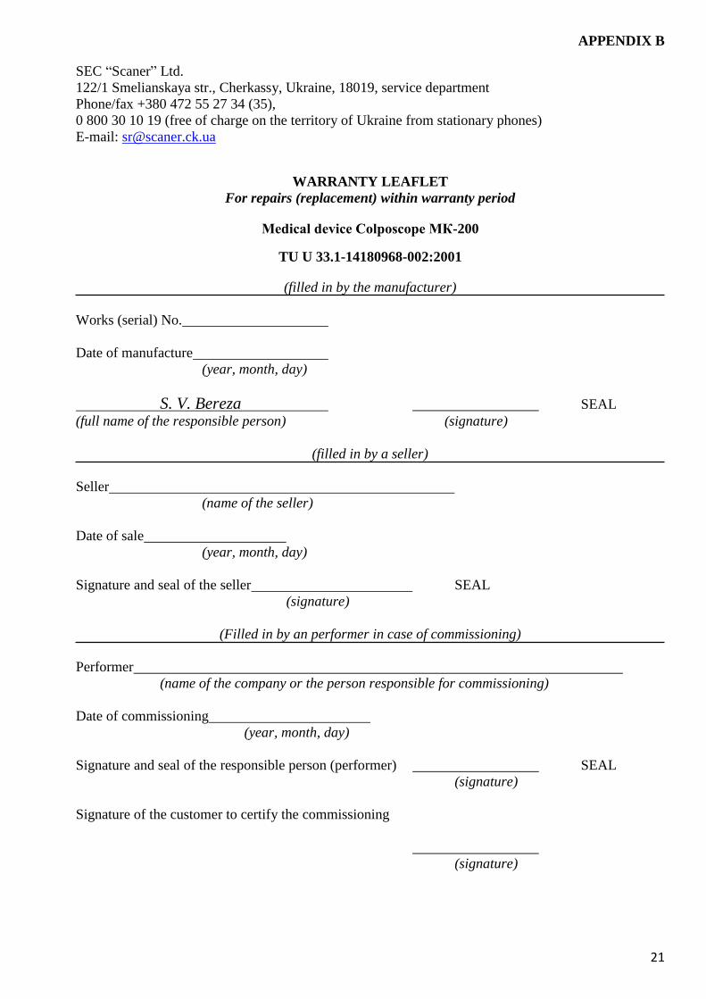
APPENDIX B
SEC “Scaner” Ltd.
122/1 Smelianskaya str., Cherkassy, Ukraine, 18019, service department
Phone/fax +380 472 55 27 34 (35),
0 800 30 10 19 (free of charge on the territory of Ukraine from stationary phones)
E-mail: [email protected]
WARRANTY LEAFLET
For repairs (replacement) within warranty period
Medical device Colposcope МК-200
TU U 33.1-14180968-002:2001
(filled in by the manufacturer)
Works (serial) No.
Date of manufacture
(year, month, day)
S. V. Bereza SEAL
(full name of the responsible person) (signature)
(filled in by a seller)
Seller
(name of the seller)
Date of sale
(year, month, day)
Signature and seal of the seller SEAL
(signature)
(Filled in by an performer in case of commissioning)
Performer
(name of the company or the person responsible for commissioning)
Date of commissioning
(year, month, day)
Signature and seal of the responsible person (performer) SEAL
(signature)
Signature of the customer to certify the commissioning
(signature)
22
SEC “Scaner” Ltd.
122/1 Smelianskaya str., Cherkassy, Ukraine, 18019,
Phone/fax +380 472 55 27 34 (35), 0 800 30 10 19
E-mail: [email protected]
DETACHABLE COUPON No.1 For repairs (replacement) within the warranty period
Medical device - Colposcope МК-200
TU U 33.1-14180968-002:2001
(filled in by the manufacturer)
Works (serial) No. Date of manufacture (year, month, day)
S. V. Bereza SEAL
(full name of the responsible person) (signature)
(filled in by a seller)
Seller
(name of the selling organization)
Dale of sale Signature and seal of the seller SEAL
(year, month, day) (signature and seal)
SEC “Scaner” Ltd.
122/1 Smelianskaya str., Cherkassy, Ukraine, 18019,
Phone/fax +380 472 55 27 34 (35), 0 800 30 10 19
E-mail: [email protected]
DETACHABLE COUPON No. 2 For repairs (replacement) within the warranty period
Medical device - Colposcope МК-200
TU U 33.1-14180968-002:2001
(filled in by the manufacturer)
Works (serial) No Date of manufacture
(year, month, day)
S. V. Bereza SEAL
(full name of the responsible person) (signature)
(filled in by a seller)
Seller
(name of the selling organization)
Date of sale Signature and seal of the seller SEAL
(year, month, day) (signature and seal)
SEC “Scaner” Ltd.
122/1 Smelianskaya str., Cherkassy, Ukraine, 18019,
Phone/fax +380 472 55 27 34 (35), 0 800 30 10 19
E-mail: [email protected]
DETACHABLE COUPON No. 3 For repairs (replacement) within the warranty period
Medical device - Colposcope МК-200
TU U 33.1-14180968-002:2001
(filled in by the manufacturer
Works (serial) No Date of manufacture
(year, month, day)
S. V. Bereza SEAL
(full name of the responsible person) (signature)
Seller
(name of the selling organization)
Date of sale Signature and seal of the seller SEAL
(year, month, day) (signature and seal)
Stu
b o
f d
eta
cha
ble
co
up
on
No
.1
Fo
r re
pa
irs
(rep
lace
men
t) w
ith
in t
he
wa
rra
nty
per
iod
Ex
trac
ted
(Yea
r, m
on
th,
da
y)
Sig
nat
ure
of
the
resp
on
sib
le p
erso
n
(sig
na
ture
)
Stu
b o
f d
eta
cha
ble
co
up
on
No
.2
Fo
r re
pa
irs
(rep
lace
men
t) w
ith
in t
he
wa
rra
nty
per
iod
Ex
trac
ted
(Yea
r, m
on
th,
da
y)
Sig
nat
ure
of
the
resp
on
sib
le p
erso
n
(sig
na
ture
)
Stu
b o
f d
eta
cha
ble
co
up
on
No
.3
Fo
r re
pa
irs
(rep
lace
men
t) w
ith
in t
he
wa
rra
nty
per
iod
Ex
trac
ted
(Yea
r, m
on
th,
da
y)
Sig
nat
ure
of
the
resp
on
sib
le p
erso
n
(sig
na
ture
)
22
(filled in by an performer)
Performer (name of the company, enterprise)
Reason for repairs Type of repairs Date of
repairs
Signature of
the performer
(full name of the responsible person) (signature)
Signature of the customer to certify the warranty repairs
(signature)
(filled in by an performer)
Performer (name of the company, enterprise)
Reason for repairs Type of repairs Date of
repairs
Signature of
the performer
(full name of the responsible person) (signature)
Signature of the customer to certify the warranty repairs
(signature)
(filled in by the performer)
Performer (name of the company, enterprise)
Reason for repairs Type of repairs Date of
repairs
Signature of
the performer
(full name of the responsible person) (signature)
Signature of the customer to certify the warranty repairs
(signature)