Embed Size (px)
Citation preview
Subject to change – Bernhard Schulz 06.04 – 1CM52
R&S CMU200 (K20,K21,K22,K23,K24,K42, K43), CMUgo
(E)GPRS Measurements with R&S CMU200
and CMUgo
This application note describes how to test and perform (E)GPRS-related measurements on mobile
phones in compliance with the GSM standard using the R&S CMU200 by means of the remote-control program CMUgo or manual operation.
(E)GPRS with CMU and CMUgo
1CM52 2 Rohde & Schwarz
Contents 1 Overview .............................................................................................3 2 Introduction..........................................................................................3 3 Manual Operation of the the R&S CMU200..........................................4
Call Setup and Release ..................................................................4 CMU200 signalling unit (B21).....................................................4 Auxiliary RF generator (AuxTX - B95) ........................................6 Automatic slot configuration .....................................................10
Measurements ..............................................................................12 Test Mode A ............................................................................12 Test Mode B ............................................................................14 EGPRS Loopback Symmetric or Asymmetric ( SRB ) ..............15 BLER.......................................................................................15
4 Remote Control of the R&S CMU200 with CMUgo.............................17 Software Features......................................................................... 17 Hardware and Software Requirements .......................................... 17
Hardware requirements............................................................17 Software requirements .............................................................17
Using CMUgo ...............................................................................17 GPRS Call Setup Module..............................................................18 GPRS Call Release Module..........................................................20 GPRS Call Change Module...........................................................21 GPRS BER/BLER Test Module.....................................................22 GSM Testset Module .................................................................... 23 GSM Call Edge Module ................................................................27 GSM Multislot Test Module...........................................................30
5 Appendix ...........................................................................................32 Table of Figures............................................................................32 Remote Sequences....................................................................... 33
GPRS Call Setup..................................................................... 33 GPRSCall Release .................................................................. 34 GPRS Call Change.................................................................. 35 GPRS BER/BLER Test ............................................................35 GSM Testset............................................................................36 GSM Call Edge........................................................................ 37 GSM Multislot Test .................................................................. 38
Abbreviations................................................................................38 References ...................................................................................38 Additional Information ................................................................... 38 Ordering Information..................................................................... 39
(E)GPRS with CMU and CMUgo
1CM52 3 Rohde & Schwarz
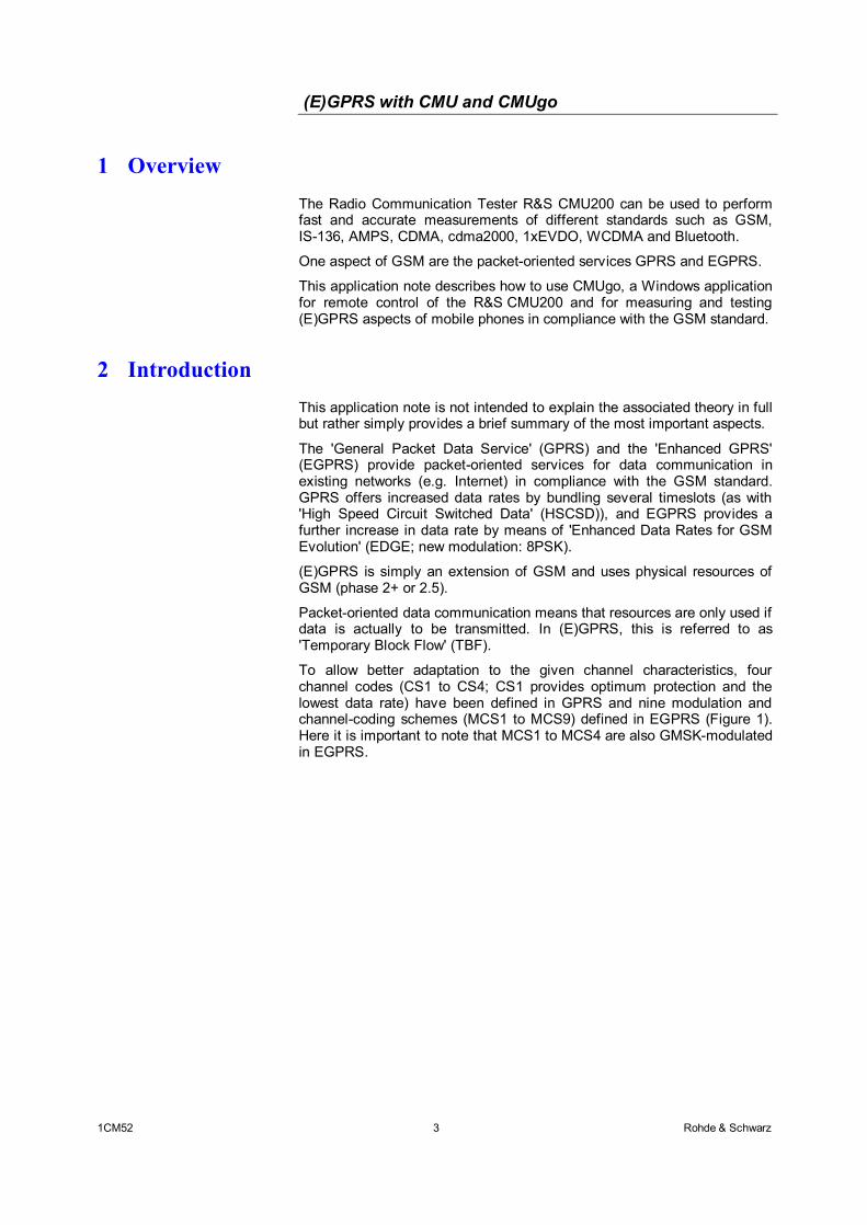
1 Overview The Radio Communication Tester R&S CMU200 can be used to perform fast and accurate measurements of different standards such as GSM, IS-136, AMPS, CDMA, cdma2000, 1xEVDO, WCDMA and Bluetooth.
One aspect of GSM are the packet-oriented services GPRS and EGPRS.
This application note describes how to use CMUgo, a Windows application for remote control of the R&S CMU200 and for measuring and testing (E)GPRS aspects of mobile phones in compliance with the GSM standard.
2 Introduction This application note is not intended to explain the associated theory in full but rather simply provides a brief summary of the most important aspects.
The 'General Packet Data Service' (GPRS) and the 'Enhanced GPRS' (EGPRS) provide packet-oriented services for data communication in existing networks (e.g. Internet) in compliance with the GSM standard. GPRS offers increased data rates by bundling several timeslots (as with 'High Speed Circuit Switched Data' (HSCSD)), and EGPRS provides a further increase in data rate by means of 'Enhanced Data Rates for GSM Evolution' (EDGE; new modulation: 8PSK).
(E)GPRS is simply an extension of GSM and uses physical resources of GSM (phase 2+ or 2.5).
Packet-oriented data communication means that resources are only used if data is actually to be transmitted. In (E)GPRS, this is referred to as 'Temporary Block Flow' (TBF).
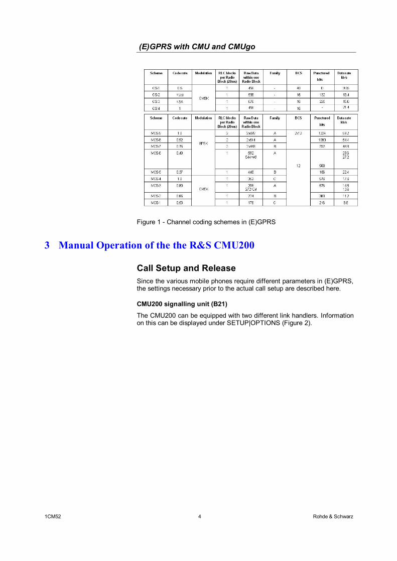
To allow better adaptation to the given channel characteristics, four channel codes (CS1 to CS4; CS1 provides optimum protection and the lowest data rate) have been defined in GPRS and nine modulation and channel-coding schemes (MCS1 to MCS9) defined in EGPRS (Figure 1). Here it is important to note that MCS1 to MCS4 are also GMSK-modulated in EGPRS.
(E)GPRS with CMU and CMUgo
1CM52 4 Rohde & Schwarz
Figure 1 - Channel coding schemes in (E)GPRS
3 Manual Operation of the the R&S CMU200
Call Setup and Release Since the various mobile phones require different parameters in (E)GPRS, the settings necessary prior to the actual call setup are described here.
CMU200 signalling unit (B21)
The CMU200 can be equipped with two different link handlers. Information on this can be displayed under SETUP|OPTIONS (Figure 2).
(E)GPRS with CMU and CMUgo
1CM52 5 Rohde & Schwarz
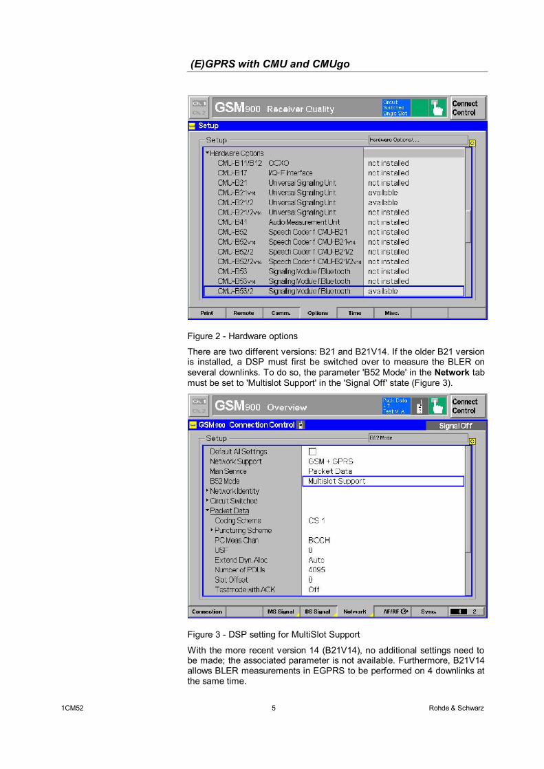
Figure 2 - Hardware options
There are two different versions: B21 and B21V14. If the older B21 version is installed, a DSP must first be switched over to measure the BLER on several downlinks. To do so, the parameter 'B52 Mode' in the Network tab must be set to 'Multislot Support' in the 'Signal Off' state (Figure 3).
Figure 3 - DSP setting for MultiSlot Support
With the more recent version 14 (B21V14), no additional settings need to be made; the associated parameter is not available. Furthermore, B21V14 allows BLER measurements in EGPRS to be performed on 4 downlinks at the same time.
(E)GPRS with CMU and CMUgo
1CM52 6 Rohde & Schwarz
Auxiliary RF generator (AuxTX - B95)
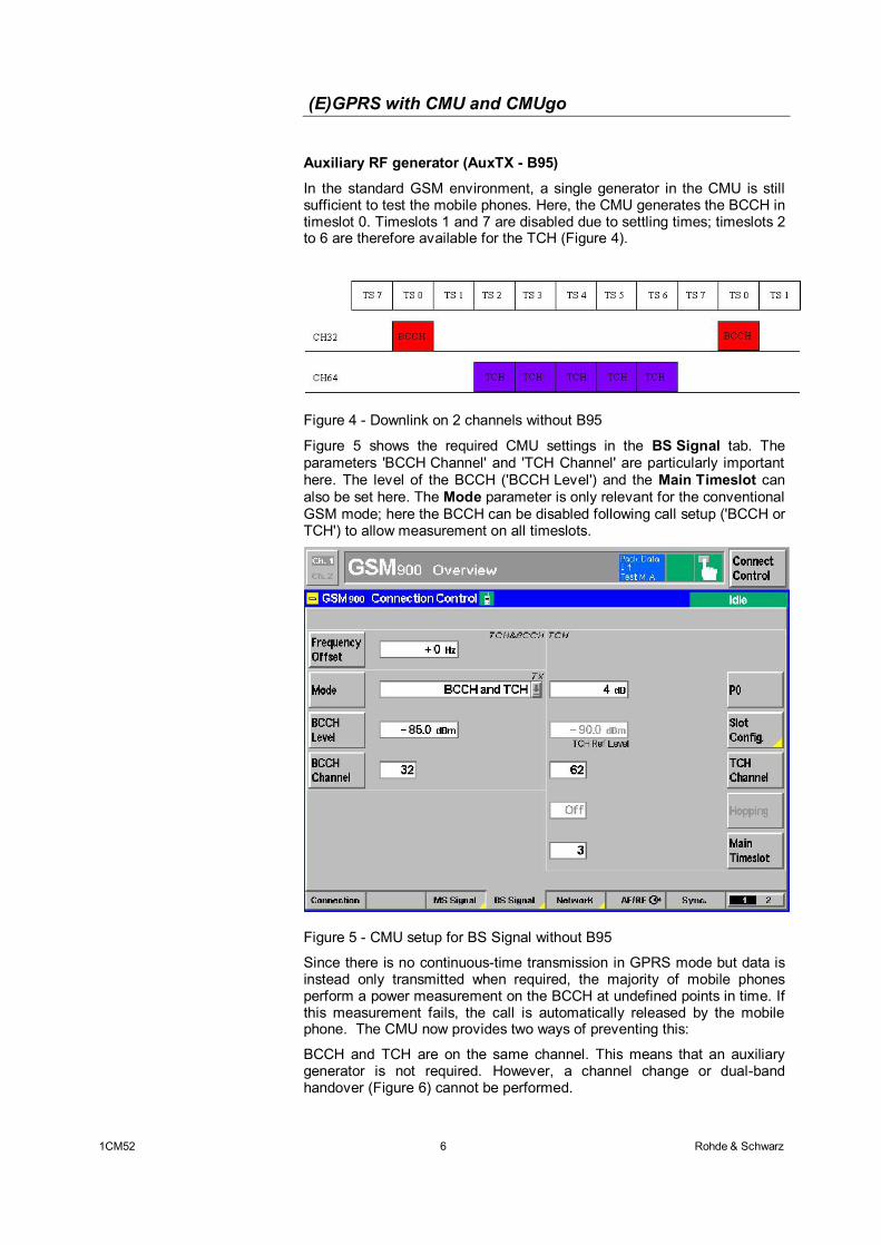
In the standard GSM environment, a single generator in the CMU is still sufficient to test the mobile phones. Here, the CMU generates the BCCH in timeslot 0. Timeslots 1 and 7 are disabled due to settling times; timeslots 2 to 6 are therefore available for the TCH (Figure 4).
Figure 4 - Downlink on 2 channels without B95
Figure 5 shows the required CMU settings in the BS Signal tab. The parameters 'BCCH Channel' and 'TCH Channel' are particularly important here. The level of the BCCH ('BCCH Level') and the Main Timeslot can also be set here. The Mode parameter is only relevant for the conventional GSM mode; here the BCCH can be disabled following call setup ('BCCH or TCH') to allow measurement on all timeslots.
Figure 5 - CMU setup for BS Signal without B95
Since there is no continuous-time transmission in GPRS mode but data is instead only transmitted when required, the majority of mobile phones perform a power measurement on the BCCH at undefined points in time. If this measurement fails, the call is automatically released by the mobile phone. The CMU now provides two ways of preventing this:
BCCH and TCH are on the same channel. This means that an auxiliary generator is not required. However, a channel change or dual-band handover (Figure 6) cannot be performed.
(E)GPRS with CMU and CMUgo
1CM52 7 Rohde & Schwarz
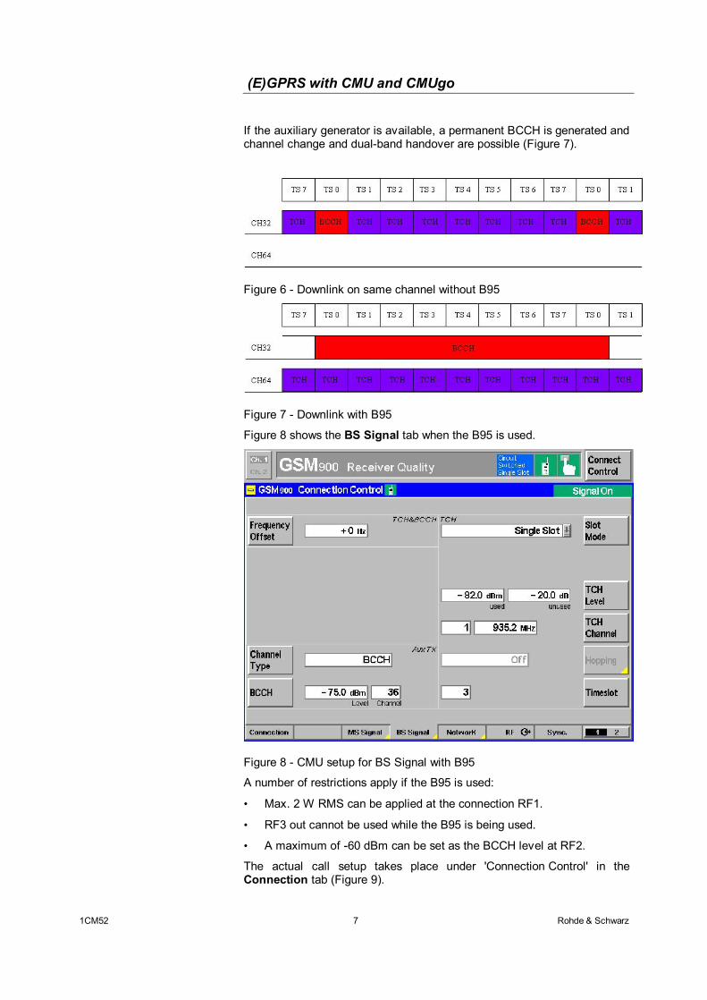
If the auxiliary generator is available, a permanent BCCH is generated and channel change and dual-band handover are possible (Figure 7).
Figure 6 - Downlink on same channel without B95
Figure 7 - Downlink with B95
Figure 8 shows the BS Signal tab when the B95 is used.
Figure 8 - CMU setup for BS Signal with B95
A number of restrictions apply if the B95 is used:
• Max. 2 W RMS can be applied at the connection RF1.
• RF3 out cannot be used while the B95 is being used.
• A maximum of -60 dBm can be set as the BCCH level at RF2.
The actual call setup takes place under 'Connection Control' in the Connection tab (Figure 9).
(E)GPRS with CMU and CMUgo
1CM52 8 Rohde & Schwarz
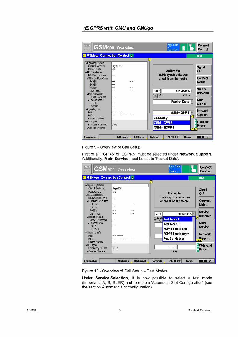
Figure 9 - Overview of Call Setup
First of all, 'GPRS' or 'EGPRS' must be selected under Network Support. Additionally, Main Service must be set to 'Packet Data'.
Figure 10 - Overview of Call Setup – Test Modes
Under Service Selection, it is now possible to select a test mode (important: A, B, BLER) and to enable 'Automatic Slot Configuration' (see the section Automatic slot configuration).
(E)GPRS with CMU and CMUgo
1CM52 9 Rohde & Schwarz
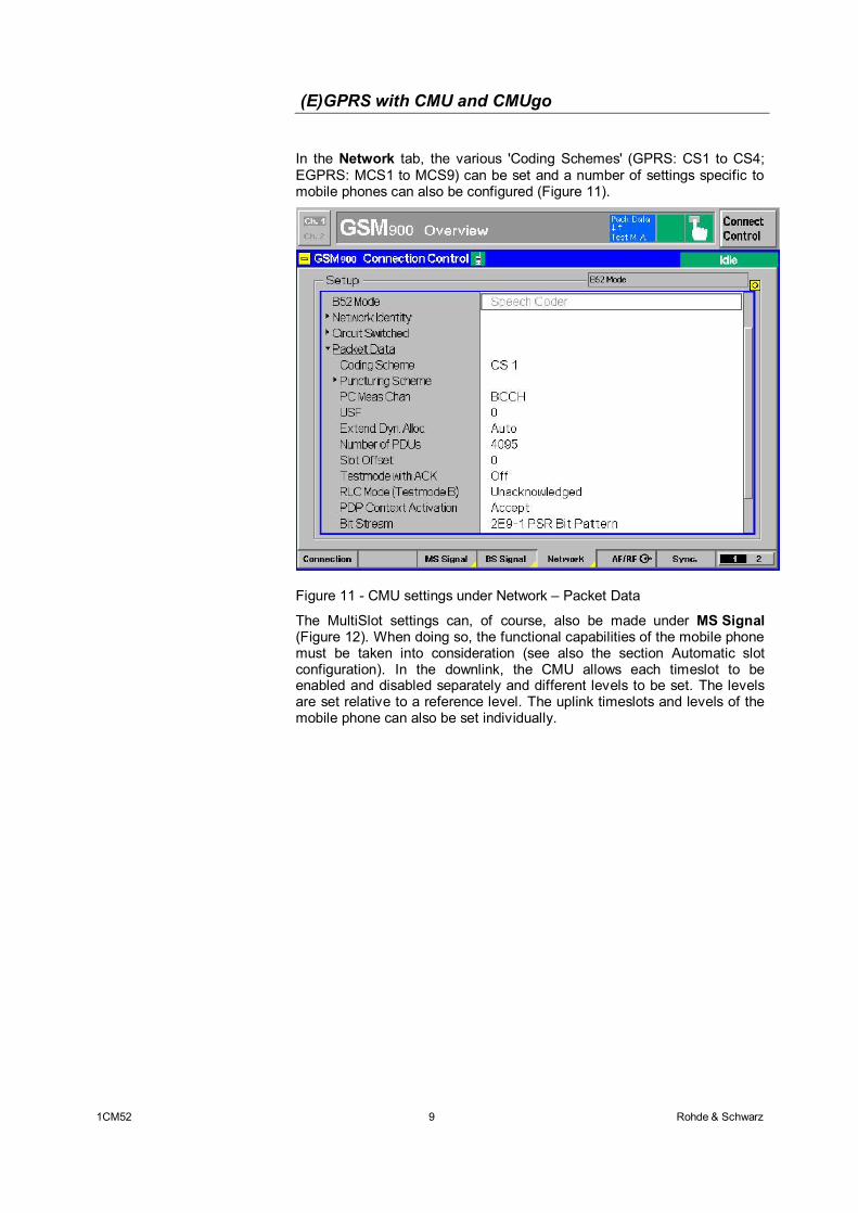
In the Network tab, the various 'Coding Schemes' (GPRS: CS1 to CS4; EGPRS: MCS1 to MCS9) can be set and a number of settings specific to mobile phones can also be configured (Figure 11).
Figure 11 - CMU settings under Network – Packet Data
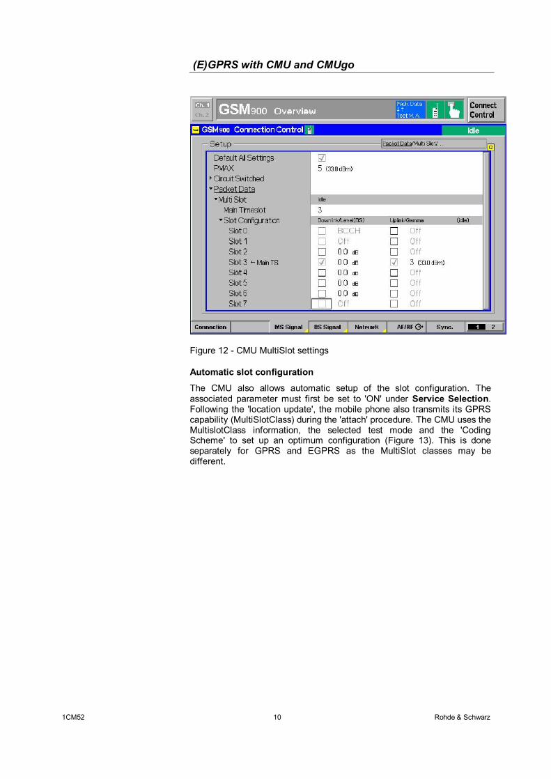
The MultiSlot settings can, of course, also be made under MS Signal (Figure 12). When doing so, the functional capabilities of the mobile phone must be taken into consideration (see also the section Automatic slot configuration). In the downlink, the CMU allows each timeslot to be enabled and disabled separately and different levels to be set. The levels are set relative to a reference level. The uplink timeslots and levels of the mobile phone can also be set individually.
(E)GPRS with CMU and CMUgo
1CM52 10 Rohde & Schwarz
Figure 12 - CMU MultiSlot settings
Automatic slot configuration
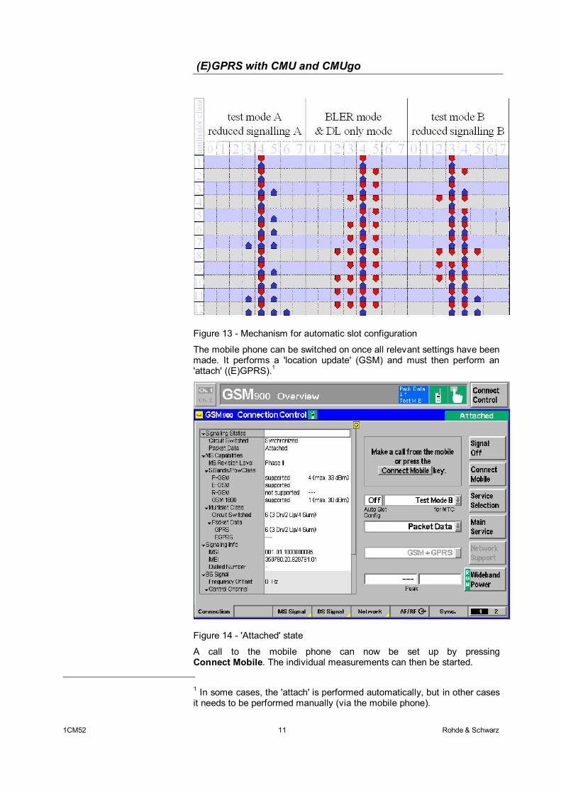
The CMU also allows automatic setup of the slot configuration. The associated parameter must first be set to 'ON' under Service Selection. Following the 'location update', the mobile phone also transmits its GPRS capability (MultiSlotClass) during the 'attach' procedure. The CMU uses the MultislotClass information, the selected test mode and the 'Coding Scheme' to set up an optimum configuration (Figure 13). This is done separately for GPRS and EGPRS as the MultiSlot classes may be different.
(E)GPRS with CMU and CMUgo
1CM52 11 Rohde & Schwarz
Figure 13 - Mechanism for automatic slot configuration
The mobile phone can be switched on once all relevant settings have been made. It performs a 'location update' (GSM) and must then perform an 'attach' ((E)GPRS).1
Figure 14 - 'Attached' state
A call to the mobile phone can now be set up by pressing Connect Mobile. The individual measurements can then be started.
1 In some cases, the 'attach' is performed automatically, but in other cases it needs to be performed manually (via the mobile phone).
(E)GPRS with CMU and CMUgo
1CM52 12 Rohde & Schwarz
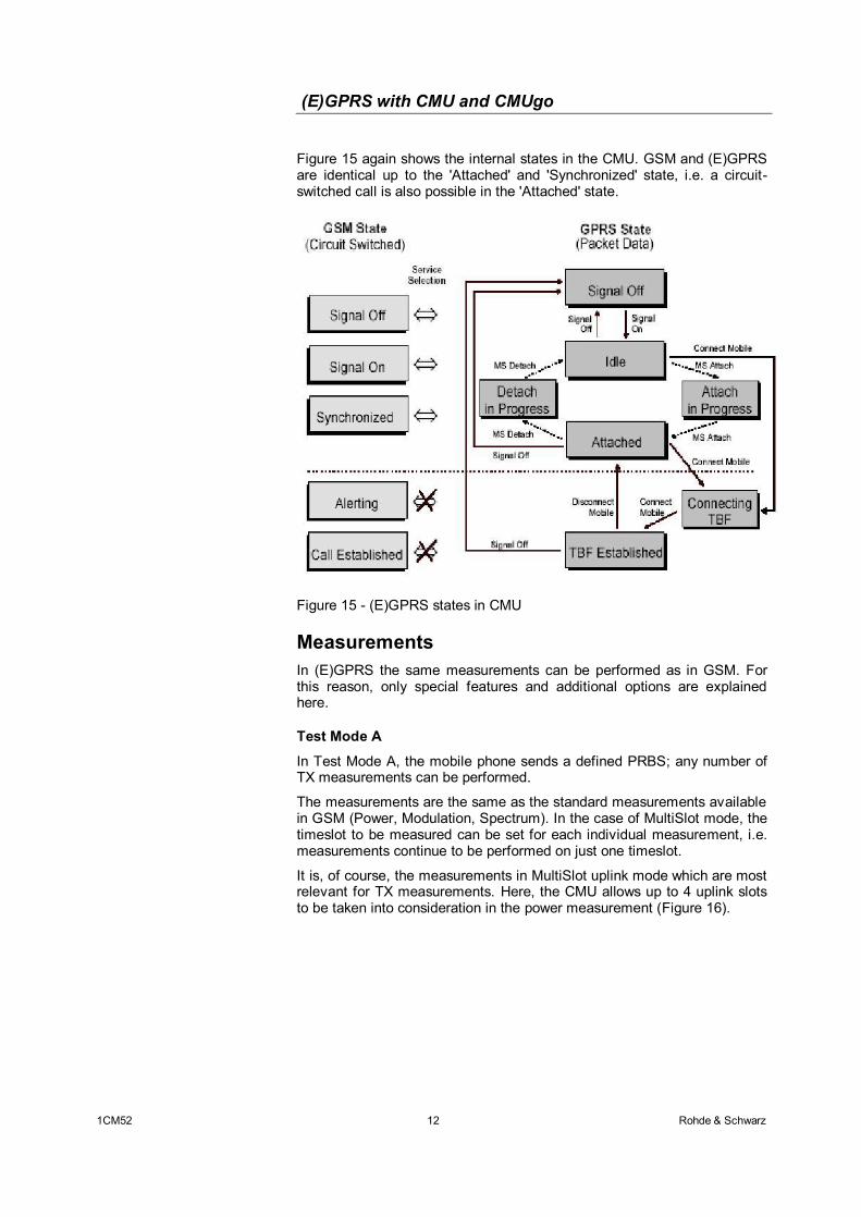
Figure 15 again shows the internal states in the CMU. GSM and (E)GPRS are identical up to the 'Attached' and 'Synchronized' state, i.e. a circuit-switched call is also possible in the 'Attached' state.
Figure 15 - (E)GPRS states in CMU
Measurements In (E)GPRS the same measurements can be performed as in GSM. For this reason, only special features and additional options are explained here.
Test Mode A
In Test Mode A, the mobile phone sends a defined PRBS; any number of TX measurements can be performed.
The measurements are the same as the standard measurements available in GSM (Power, Modulation, Spectrum). In the case of MultiSlot mode, the timeslot to be measured can be set for each individual measurement, i.e. measurements continue to be performed on just one timeslot.
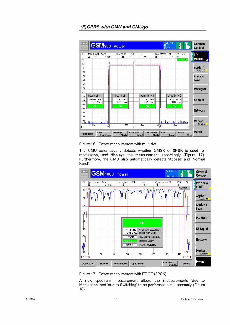
It is, of course, the measurements in MultiSlot uplink mode which are most relevant for TX measurements. Here, the CMU allows up to 4 uplink slots to be taken into consideration in the power measurement (Figure 16).
(E)GPRS with CMU and CMUgo
1CM52 13 Rohde & Schwarz
Figure 16 - Power measurement with multislot
The CMU automatically detects whether GMSK or 8PSK is used for modulation, and displays the measurement accordingly (Figure 17). Furthermore, the CMU also automatically detects 'Access' and 'Normal Burst'.
Figure 17 - Power measurement with EDGE (8PSK)
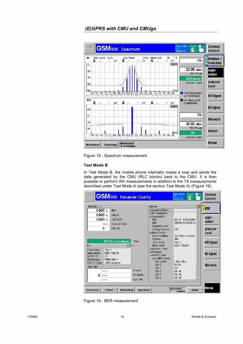
A new spectrum measurement allows the measurements 'due to Modulation' and 'due to Switching' to be performed simultaneously (Figure 18).
(E)GPRS with CMU and CMUgo
1CM52 14 Rohde & Schwarz
Figure 18 - Spectrum measurement
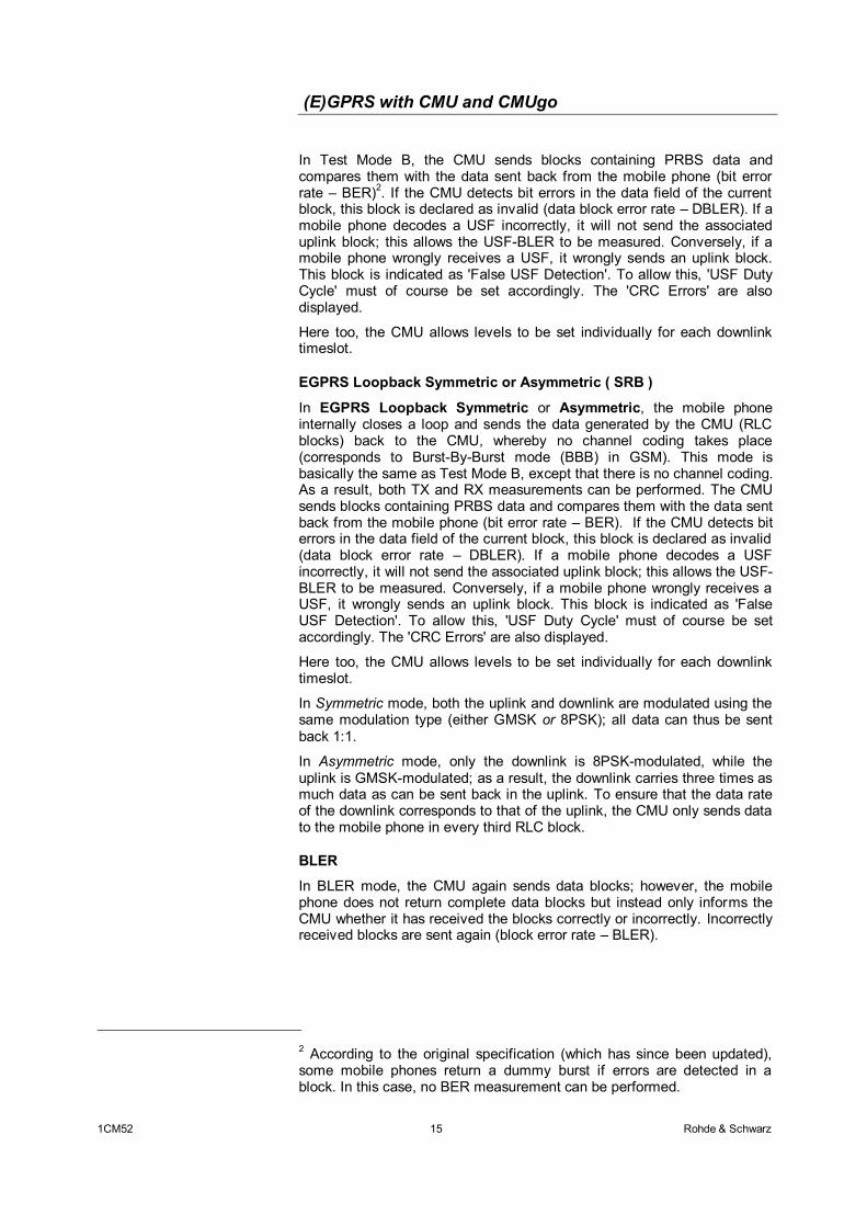
Test Mode B
In Test Mode B, the mobile phone internally closes a loop and sends the data generated by the CMU (RLC blocks) back to the CMU. It is then possible to perform RX measurements in addition to the TX measurements described under Test Mode A (see the section Test Mode A) (Figure 19).
Figure 19 - BER measurement
(E)GPRS with CMU and CMUgo
1CM52 15 Rohde & Schwarz
In Test Mode B, the CMU sends blocks containing PRBS data and compares them with the data sent back from the mobile phone (bit error rate – BER)2. If the CMU detects bit errors in the data field of the current block, this block is declared as invalid (data block error rate – DBLER). If a mobile phone decodes a USF incorrectly, it will not send the associated uplink block; this allows the USF-BLER to be measured. Conversely, if a mobile phone wrongly receives a USF, it wrongly sends an uplink block. This block is indicated as 'False USF Detection'. To allow this, 'USF Duty Cycle' must of course be set accordingly. The 'CRC Errors' are also displayed.
Here too, the CMU allows levels to be set individually for each downlink timeslot.
EGPRS Loopback Symmetric or Asymmetric ( SRB )
In EGPRS Loopback Symmetric or Asymmetric, the mobile phone internally closes a loop and sends the data generated by the CMU (RLC blocks) back to the CMU, whereby no channel coding takes place (corresponds to Burst-By-Burst mode (BBB) in GSM). This mode is basically the same as Test Mode B, except that there is no channel coding. As a result, both TX and RX measurements can be performed. The CMU sends blocks containing PRBS data and compares them with the data sent back from the mobile phone (bit error rate – BER). If the CMU detects bit errors in the data field of the current block, this block is declared as invalid (data block error rate – DBLER). If a mobile phone decodes a USF incorrectly, it will not send the associated uplink block; this allows the USF-BLER to be measured. Conversely, if a mobile phone wrongly receives a USF, it wrongly sends an uplink block. This block is indicated as 'False USF Detection'. To allow this, 'USF Duty Cycle' must of course be set accordingly. The 'CRC Errors' are also displayed.
Here too, the CMU allows levels to be set individually for each downlink timeslot.
In Symmetric mode, both the uplink and downlink are modulated using the same modulation type (either GMSK or 8PSK); all data can thus be sent back 1:1.
In Asymmetric mode, only the downlink is 8PSK-modulated, while the uplink is GMSK-modulated; as a result, the downlink carries three times as much data as can be sent back in the uplink. To ensure that the data rate of the downlink corresponds to that of the uplink, the CMU only sends data to the mobile phone in every third RLC block.
BLER
In BLER mode, the CMU again sends data blocks; however, the mobile phone does not return complete data blocks but instead only informs the CMU whether it has received the blocks correctly or incorrectly. Incorrectly received blocks are sent again (block error rate – BLER).
2 According to the original specification (which has since been updated), some mobile phones return a dummy burst if errors are detected in a block. In this case, no BER measurement can be performed.
(E)GPRS with CMU and CMUgo
1CM52 16 Rohde & Schwarz
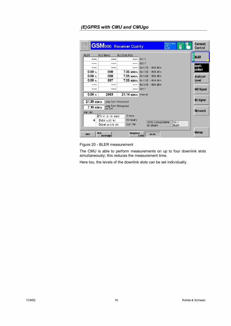
Figure 20 - BLER measurement
The CMU is able to perform measurements on up to four downlink slots simultaneously; this reduces the measurement time.
Here too, the levels of the downlink slots can be set individually.
(E)GPRS with CMU and CMUgo
1CM52 17 Rohde & Schwarz
4 Remote Control of the R&S CMU200 with CMUgo
Software Features CMUgo offers a simple user interface for remote control of the R&S CMU200 for all standards available on the R&S CMU200 both via a GPIB bus (IEE488.2) and via the RS-232-C interface.
CMUgo includes a feature for outputting test reports. Moreover, a report of remote-control commands with the times of the individual items can be output and the remote-control commands can be copied directly to the Windows clipboard for further processing.
Hardware and Software Requirements
Hardware requirements
• CPU: min. 300 MHz
• RAM: min. 64 MByte
• Monitor: SVGA with min. 800 x 600 pixels
• Hard disk: 50 MByte of free memory
• Peripherals: National Instruments GPIB bus or RS-232-C interface, mouse
Software requirements
• Windows 98 / ME / 2000 / XP
• CMUgo V1.45 with GSM/GPRS modules V1.45 or newer
Using CMUgo Please refer to the CMUgo manual [2] for information on how to connect the computer and the R&S CMU200, as well as how to install, start and operate CMUgo.
With CMUgo, the remote sequence can be output by using the Demo function. Individual sequences can then be created based on this sequence. CMUgo tries to perform the test sequences as quickly as possible. Since the program is structured as a sequencer (information about the previous module is not available), it is sometimes possible to save time by making additional optimizations.
Note: All modules with the prefix 'GSM' can also be used in (E)GPRS. Single parameters or measurements are, however, of little use and are therefore not taken into consideration. Reference to these restrictions is made again in the descriptions of the individual (GSM) modules in this document.
(E)GPRS with CMU and CMUgo
1CM52 18 Rohde & Schwarz
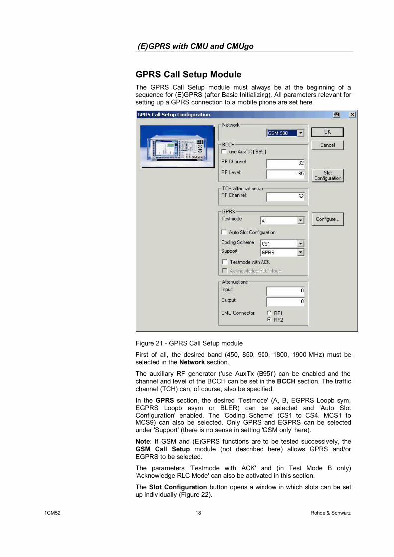
GPRS Call Setup Module The GPRS Call Setup module must always be at the beginning of a sequence for (E)GPRS (after Basic Initializing). All parameters relevant for setting up a GPRS connection to a mobile phone are set here.
Figure 21 - GPRS Call Setup module
First of all, the desired band (450, 850, 900, 1800, 1900 MHz) must be selected in the Network section.
The auxiliary RF generator ('use AuxTx (B95)') can be enabled and the channel and level of the BCCH can be set in the BCCH section. The traffic channel (TCH) can, of course, also be specified.
In the GPRS section, the desired 'Testmode' (A, B, EGPRS Loopb sym, EGPRS Loopb asym or BLER) can be selected and 'Auto Slot Configuration' enabled. The 'Coding Scheme' (CS1 to CS4, MCS1 to MCS9) can also be selected. Only GPRS and EGPRS can be selected under 'Support' (there is no sense in setting 'GSM only' here).
Note: If GSM and (E)GPRS functions are to be tested successively, the GSM Call Setup module (not described here) allows GPRS and/or EGPRS to be selected.
The parameters 'Testmode with ACK' and (in Test Mode B only) 'Acknowledge RLC Mode' can also be activated in this section.
The Slot Configuration button opens a window in which slots can be set up individually (Figure 22).
(E)GPRS with CMU and CMUgo
1CM52 19 Rohde & Schwarz
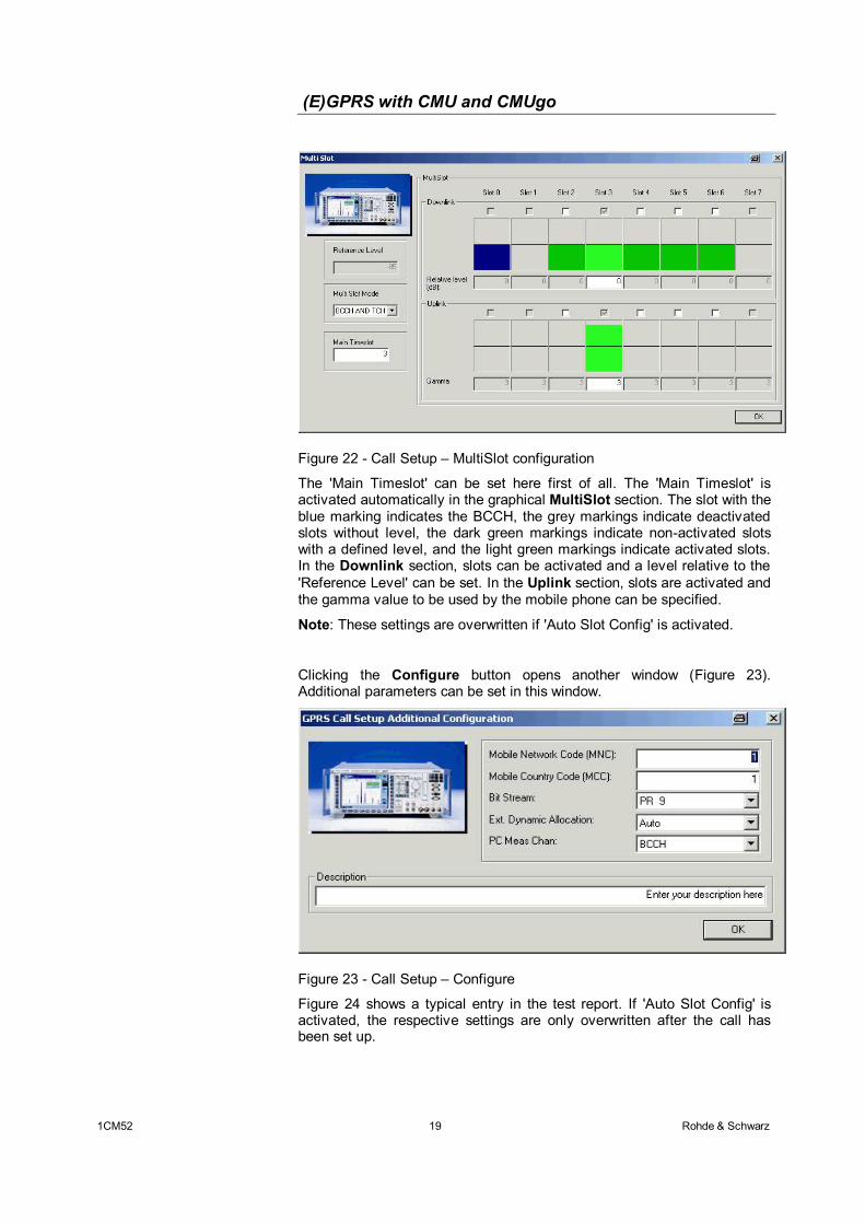
Figure 22 - Call Setup – MultiSlot configuration
The 'Main Timeslot' can be set here first of all. The 'Main Timeslot' is activated automatically in the graphical MultiSlot section. The slot with the blue marking indicates the BCCH, the grey markings indicate deactivated slots without level, the dark green markings indicate non-activated slots with a defined level, and the light green markings indicate activated slots. In the Downlink section, slots can be activated and a level relative to the 'Reference Level' can be set. In the Uplink section, slots are activated and the gamma value to be used by the mobile phone can be specified.
Note: These settings are overwritten if 'Auto Slot Config' is activated.
Clicking the Configure button opens another window (Figure 23). Additional parameters can be set in this window.
Figure 23 - Call Setup – Configure
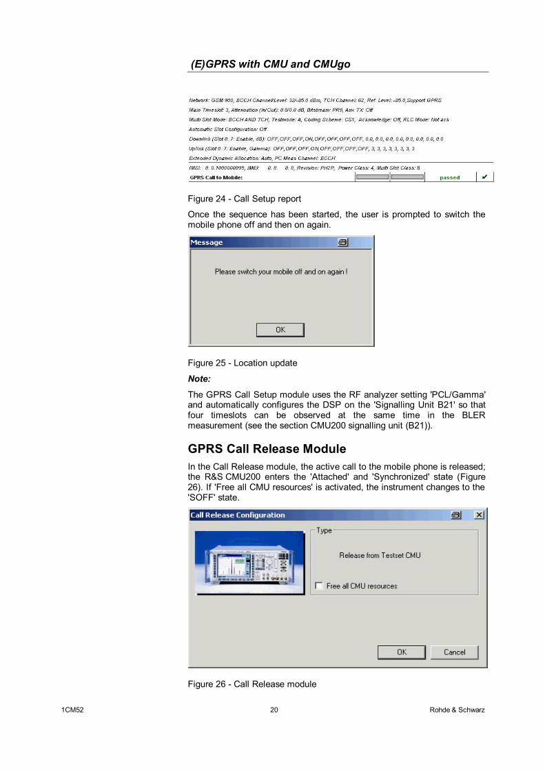
Figure 24 shows a typical entry in the test report. If 'Auto Slot Config' is activated, the respective settings are only overwritten after the call has been set up.
(E)GPRS with CMU and CMUgo
1CM52 20 Rohde & Schwarz
Figure 24 - Call Setup report
Once the sequence has been started, the user is prompted to switch the mobile phone off and then on again.
Figure 25 - Location update
Note:
The GPRS Call Setup module uses the RF analyzer setting 'PCL/Gamma' and automatically configures the DSP on the 'Signalling Unit B21' so that four timeslots can be observed at the same time in the BLER measurement (see the section CMU200 signalling unit (B21)).
GPRS Call Release Module In the Call Release module, the active call to the mobile phone is released; the R&S CMU200 enters the 'Attached' and 'Synchronized' state (Figure 26). If 'Free all CMU resources' is activated, the instrument changes to the 'SOFF' state.
Figure 26 - Call Release module
(E)GPRS with CMU and CMUgo
1CM52 21 Rohde & Schwarz
If the call is not set up or released, the following window will be displayed (Figure 27). This query is also performed by all other modules (except for Call Setup).
Figure 27 - Information: No connection
Figure 28 shows the Call Release entry in the test report.
Figure 28 - Call Release report
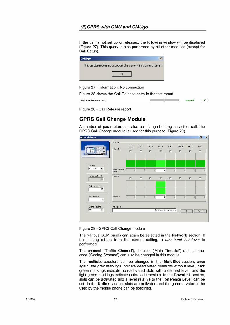
GPRS Call Change Module A number of parameters can also be changed during an active call; the GPRS Call Change module is used for this purpose (Figure 29).
Figure 29 - GPRS Call Change module
The various GSM bands can again be selected in the Network section. If this setting differs from the current setting, a dual-band handover is performed.
The channel ('Traffic Channel'), timeslot ('Main Timeslot') and channel code ('Coding Scheme') can also be changed in this module.
The multislot structure can be changed in the MultiSlot section; once again, the grey markings indicate deactivated timeslots without level, dark green markings indicate non-activated slots with a defined level, and the light green markings indicate activated timeslots. In the Downlink section, slots can be activated and a level relative to the 'Reference Level' can be set. In the Uplink section, slots are activated and the gamma value to be used by the mobile phone can be specified.
(E)GPRS with CMU and CMUgo
1CM52 22 Rohde & Schwarz
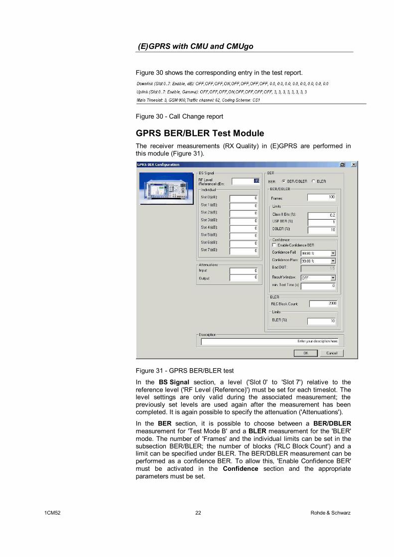
Figure 30 shows the corresponding entry in the test report.
Figure 30 - Call Change report
GPRS BER/BLER Test Module The receiver measurements (RX Quality) in (E)GPRS are performed in this module (Figure 31).
Figure 31 - GPRS BER/BLER test
In the BS Signal section, a level ('Slot 0' to 'Slot 7') relative to the reference level ('RF Level (Reference)') must be set for each timeslot. The level settings are only valid during the associated measurement; the previously set levels are used again after the measurement has been completed. It is again possible to specify the attenuation ('Attenuations').
In the BER section, it is possible to choose between a BER/DBLER measurement for 'Test Mode B' and a BLER measurement for the 'BLER' mode. The number of 'Frames' and the individual limits can be set in the subsection BER/BLER; the number of blocks ('RLC Block Count') and a limit can be specified under BLER. The BER/DBLER measurement can be performed as a confidence BER. To allow this, 'Enable Confidence BER' must be activated in the Confidence section and the appropriate parameters must be set.
(E)GPRS with CMU and CMUgo
1CM52 23 Rohde & Schwarz
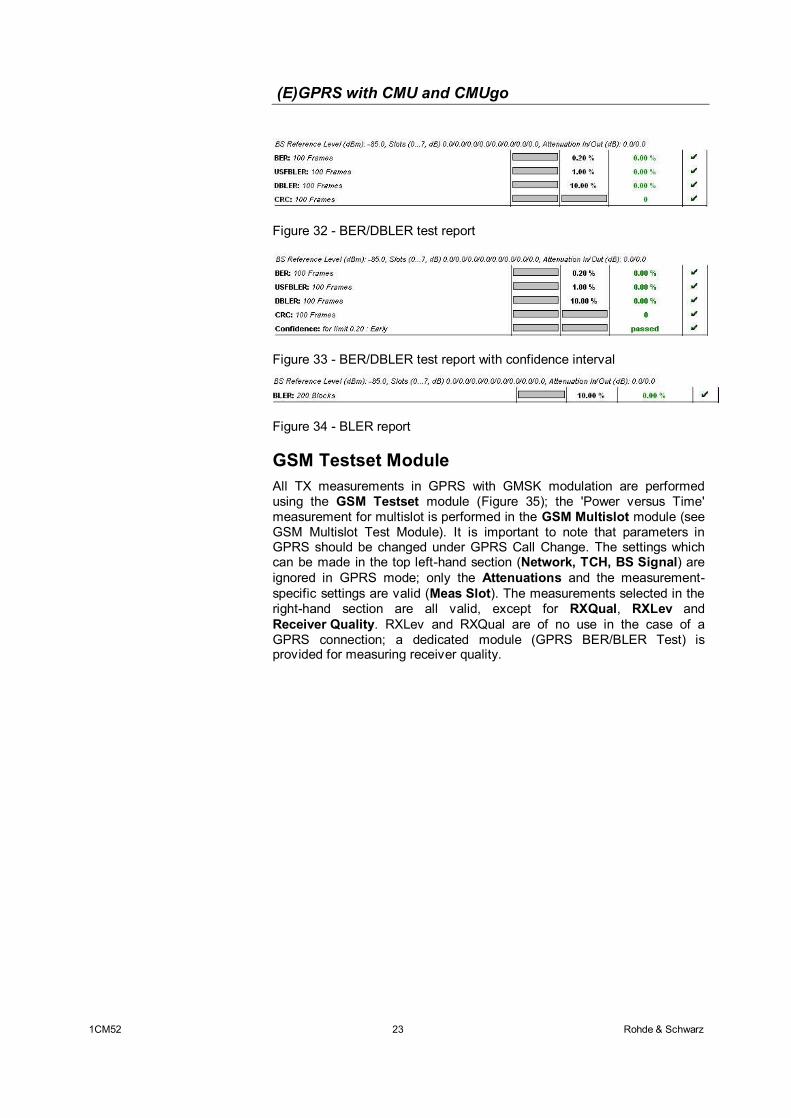
Figure 32 - BER/DBLER test report
Figure 33 - BER/DBLER test report with confidence interval
Figure 34 - BLER report
GSM Testset Module All TX measurements in GPRS with GMSK modulation are performed using the GSM Testset module (Figure 35); the 'Power versus Time' measurement for multislot is performed in the GSM Multislot module (see GSM Multislot Test Module). It is important to note that parameters in GPRS should be changed under GPRS Call Change. The settings which can be made in the top left-hand section (Network, TCH, BS Signal) are ignored in GPRS mode; only the Attenuations and the measurement-specific settings are valid (Meas Slot). The measurements selected in the right-hand section are all valid, except for RXQual, RXLev and Receiver Quality. RXLev and RXQual are of no use in the case of a GPRS connection; a dedicated module (GPRS BER/BLER Test) is provided for measuring receiver quality.
(E)GPRS with CMU and CMUgo
1CM52 24 Rohde & Schwarz
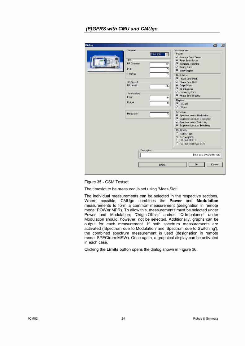
Figure 35 - GSM Testset
The timeslot to be measured is set using 'Meas Slot'.
The individual measurements can be selected in the respective sections. Where possible, CMUgo combines the Power and Modulation measurements to form a common measurement (designation in remote mode: POWer:MPR). To allow this, measurements must be selected under Power and Modulation; 'Origin Offset' and/or 'IQ Imbalance' under Modulation should, however, not be selected. Additionally, graphs can be output for each measurement. If both spectrum measurements are activated ('Spectrum due to Modulation' and 'Spectrum due to Switching'), the combined spectrum measurement is used (designation in remote mode: SPECtrum:MSW). Once again, a graphical display can be activated in each case.
Clicking the Limits button opens the dialog shown in Figure 36.
(E)GPRS with CMU and CMUgo
1CM52 25 Rohde & Schwarz
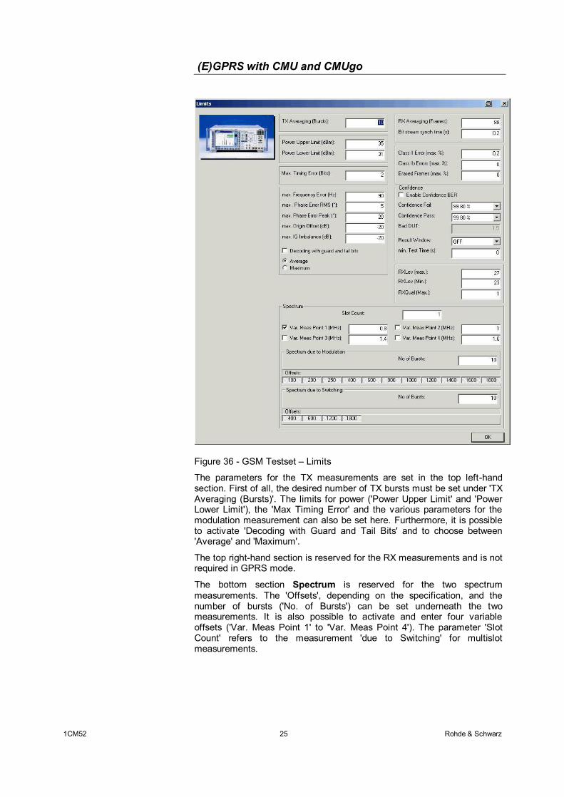
Figure 36 - GSM Testset – Limits
The parameters for the TX measurements are set in the top left-hand section. First of all, the desired number of TX bursts must be set under 'TX Averaging (Bursts)'. The limits for power ('Power Upper Limit' and 'Power Lower Limit'), the 'Max Timing Error' and the various parameters for the modulation measurement can also be set here. Furthermore, it is possible to activate 'Decoding with Guard and Tail Bits' and to choose between 'Average' and 'Maximum'.
The top right-hand section is reserved for the RX measurements and is not required in GPRS mode.
The bottom section Spectrum is reserved for the two spectrum measurements. The 'Offsets', depending on the specification, and the number of bursts ('No. of Bursts') can be set underneath the two measurements. It is also possible to activate and enter four variable offsets ('Var. Meas Point 1' to 'Var. Meas Point 4'). The parameter 'Slot Count' refers to the measurement 'due to Switching' for multislot measurements.
(E)GPRS with CMU and CMUgo
1CM52 26 Rohde & Schwarz
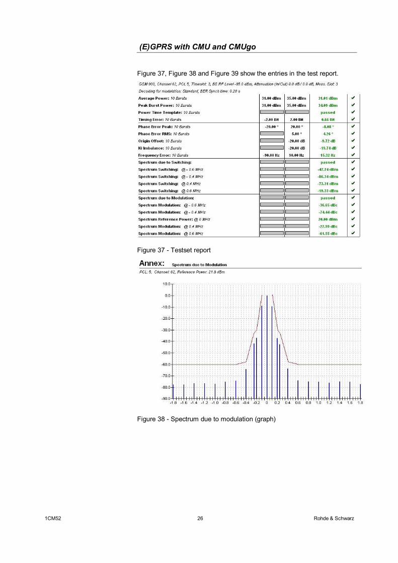
Figure 37, Figure 38 and Figure 39 show the entries in the test report.
Figure 37 - Testset report
Figure 38 - Spectrum due to modulation (graph)
(E)GPRS with CMU and CMUgo
1CM52 27 Rohde & Schwarz
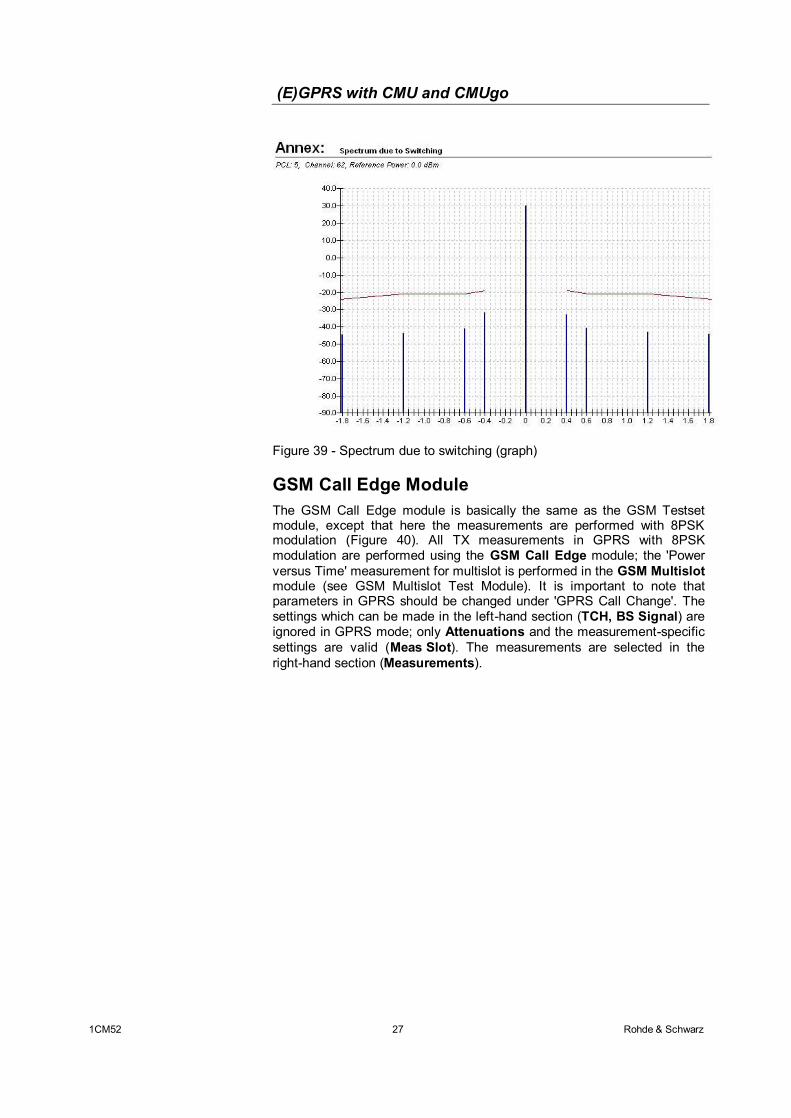
Figure 39 - Spectrum due to switching (graph)
GSM Call Edge Module The GSM Call Edge module is basically the same as the GSM Testset module, except that here the measurements are performed with 8PSK modulation (Figure 40). All TX measurements in GPRS with 8PSK modulation are performed using the GSM Call Edge module; the 'Power versus Time' measurement for multislot is performed in the GSM Multislot module (see GSM Multislot Test Module). It is important to note that parameters in GPRS should be changed under 'GPRS Call Change'. The settings which can be made in the left-hand section (TCH, BS Signal) are ignored in GPRS mode; only Attenuations and the measurement-specific settings are valid (Meas Slot). The measurements are selected in the right-hand section (Measurements).
(E)GPRS with CMU and CMUgo
1CM52 28 Rohde & Schwarz
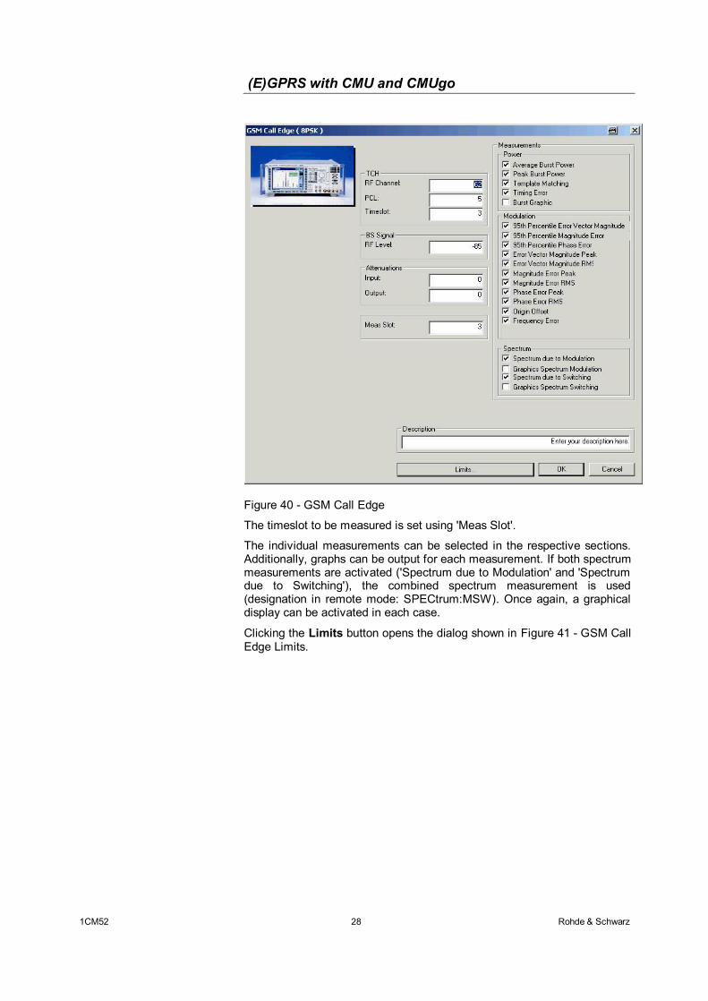
Figure 40 - GSM Call Edge
The timeslot to be measured is set using 'Meas Slot'.
The individual measurements can be selected in the respective sections. Additionally, graphs can be output for each measurement. If both spectrum measurements are activated ('Spectrum due to Modulation' and 'Spectrum due to Switching'), the combined spectrum measurement is used (designation in remote mode: SPECtrum:MSW). Once again, a graphical display can be activated in each case.
Clicking the Limits button opens the dialog shown in Figure 41 - GSM Call Edge Limits.
(E)GPRS with CMU and CMUgo
1CM52 29 Rohde & Schwarz
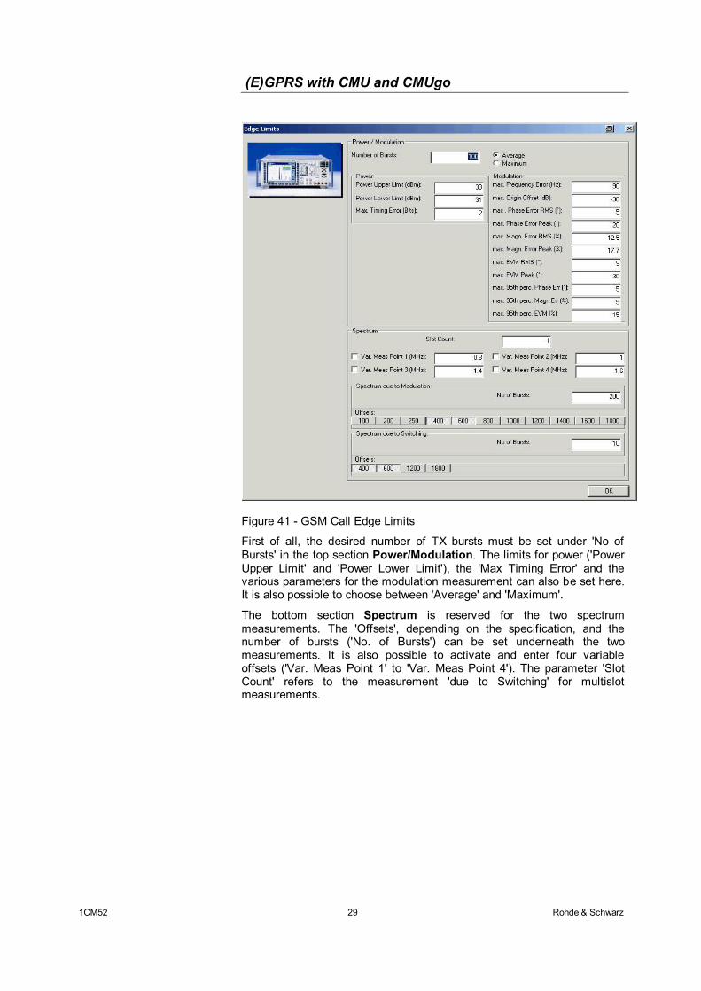
Figure 41 - GSM Call Edge Limits
First of all, the desired number of TX bursts must be set under 'No of Bursts' in the top section Power/Modulation. The limits for power ('Power Upper Limit' and 'Power Lower Limit'), the 'Max Timing Error' and the various parameters for the modulation measurement can also be set here. It is also possible to choose between 'Average' and 'Maximum'.
The bottom section Spectrum is reserved for the two spectrum measurements. The 'Offsets', depending on the specification, and the number of bursts ('No. of Bursts') can be set underneath the two measurements. It is also possible to activate and enter four variable offsets ('Var. Meas Point 1' to 'Var. Meas Point 4'). The parameter 'Slot Count' refers to the measurement 'due to Switching' for multislot measurements.
(E)GPRS with CMU and CMUgo
1CM52 30 Rohde & Schwarz
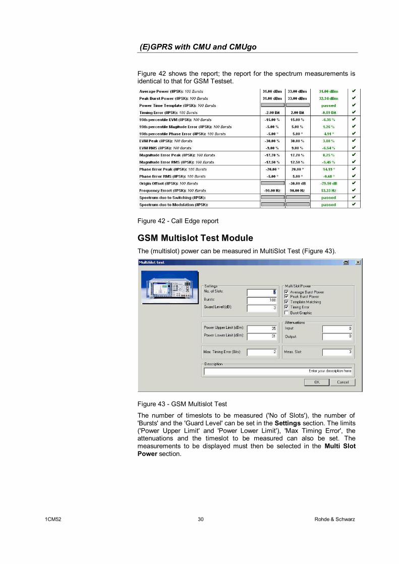
Figure 42 shows the report; the report for the spectrum measurements is identical to that for GSM Testset.
Figure 42 - Call Edge report
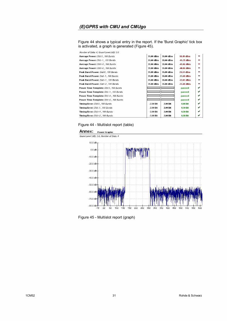
GSM Multislot Test Module The (multislot) power can be measured in MultiSlot Test (Figure 43).
Figure 43 - GSM Multislot Test
The number of timeslots to be measured ('No of Slots'), the number of 'Bursts' and the 'Guard Level' can be set in the Settings section. The limits ('Power Upper Limit' and 'Power Lower Limit'), 'Max Timing Error', the attenuations and the timeslot to be measured can also be set. The measurements to be displayed must then be selected in the Multi Slot Power section.
(E)GPRS with CMU and CMUgo
1CM52 31 Rohde & Schwarz
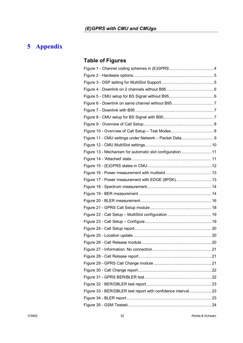
Figure 44 shows a typical entry in the report. If the 'Burst Graphic' tick box is activated, a graph is generated (Figure 45).
Figure 44 - Multislot report (table)
Figure 45 - Multislot report (graph)
(E)GPRS with CMU and CMUgo
1CM52 32 Rohde & Schwarz
5 Appendix
Table of Figures Figure 1 - Channel coding schemes in (E)GPRS....................................... 4 Figure 2 - Hardware options...................................................................... 5 Figure 3 - DSP setting for MultiSlot Support..............................................5 Figure 4 - Downlink on 2 channels without B95 ......................................... 6 Figure 5 - CMU setup for BS Signal without B95....................................... 6 Figure 6 - Downlink on same channel without B95 .................................... 7 Figure 7 - Downlink with B95 .................................................................... 7 Figure 8 - CMU setup for BS Signal with B95............................................ 7 Figure 9 - Overview of Call Setup.............................................................8 Figure 10 - Overview of Call Setup – Test Modes..................................... 8 Figure 11 - CMU settings under Network – Packet Data............................9 Figure 12 - CMU MultiSlot settings.......................................................... 10 Figure 13 - Mechanism for automatic slot configuration .......................... 11 Figure 14 - 'Attached' state ..................................................................... 11 Figure 15 - (E)GPRS states in CMU........................................................ 12 Figure 16 - Power measurement with multislot ........................................ 13 Figure 17 - Power measurement with EDGE (8PSK)...............................13 Figure 18 - Spectrum measurement........................................................ 14 Figure 19 - BER measurement ...............................................................14 Figure 20 - BLER measurement..............................................................16 Figure 21 - GPRS Call Setup module ..................................................... 18 Figure 22 - Call Setup – MultiSlot configuration ...................................... 19 Figure 23 - Call Setup – Configure.......................................................... 19 Figure 24 - Call Setup report................................................................... 20 Figure 25 - Location update .................................................................... 20 Figure 26 - Call Release module.............................................................20 Figure 27 - Information: No connection ................................................... 21 Figure 28 - Call Release report ...............................................................21 Figure 29 - GPRS Call Change module .................................................. 21 Figure 30 - Call Change report................................................................22 Figure 31 - GPRS BER/BLER test .......................................................... 22 Figure 32 - BER/DBLER test report......................................................... 23 Figure 33 - BER/DBLER test report with confidence interval ................... 23 Figure 34 - BLER report.......................................................................... 23 Figure 35 - GSM Testset......................................................................... 24
(E)GPRS with CMU and CMUgo
1CM52 33 Rohde & Schwarz
Figure 36 - GSM Testset – Limits ...........................................................25 Figure 37 - Testset report........................................................................ 26 Figure 38 - Spectrum due to modulation (graph) ..................................... 26 Figure 39 - Spectrum due to switching (graph)........................................ 27 Figure 40 - GSM Call Edge..................................................................... 28 Figure 41 - GSM Call Edge Limits...........................................................29 Figure 42 - Call Edge report.................................................................... 30 Figure 43 - GSM Multislot Test ...............................................................30 Figure 44 - Multislot report (table) ...........................................................31 Figure 45 - Multislot report (graph).......................................................... 31
Remote Sequences
GPRS Call Setup
First of all, the RF analyzer is set to PCL/Gamma mode, the RF connector ( RF2 ) is selected and the attenuation ( 0 dB ) is set. LEV:MODE PCL
SIGN:STAT?
INP:STAT RF2
OUTP:STAT RF2
SENS:CORR:LOSS:INP2 0.0
SENS:CORR:LOSS:OUTP2 0.0
Setting of Network Support (GSM+GPRS), DSP B52 of B21V02 ( Multislot Support ) and parameter P-Zero ( 0 ). Also channel of the BCCH ( 32 ) and level (-85 dBm) as well as the traffic channel ( 62 ) and the main timeslot ( 3 ). CONF:NETW:NSUP GGPR
CONF:NETW:B52M MSUP
CONF:BSS:PDAT:MSL:PZER 0
CONF:BSS:CCH:CHAN 32
CONF:BSS:CCH:LEV -85.0
CONF:BSS:PDAT:TCH:MSL:CHAN 62
CONF:BSS:PDAT:TCH:MSL:MTIM 3
CONF:SIGN:PDAT:ASC:ENAB OFF
Setting of multislot uplink (slot 3 ON, gamma all 3) and downlink (slot 3, all 0 dB relative), coding scheme ( CS1 ) CONF:MSS:PDAT:TCH:MSL:SCON OFF,OFF,OFF,ON,OFF,OFF,OFF,OFF,3,3,3,3,3,3,3,3
CONF:BSS:PDAT:TCH:MSL:SCON
OFF,OFF,OFF,ON,OFF,OFF,OFF,OFF,0.0,0.0,0.0,0.0,0.0,0.0,0.0,0.0
CONF:NETW:PDAT:GPRS:CSCH CS1
Acknowledge mode (Off), controchannel mode (BCCH and TCH) CONF:NETW:PDAT:TWAC OFF
(E)GPRS with CMU and CMUgo
1CM52 34 Rohde & Schwarz
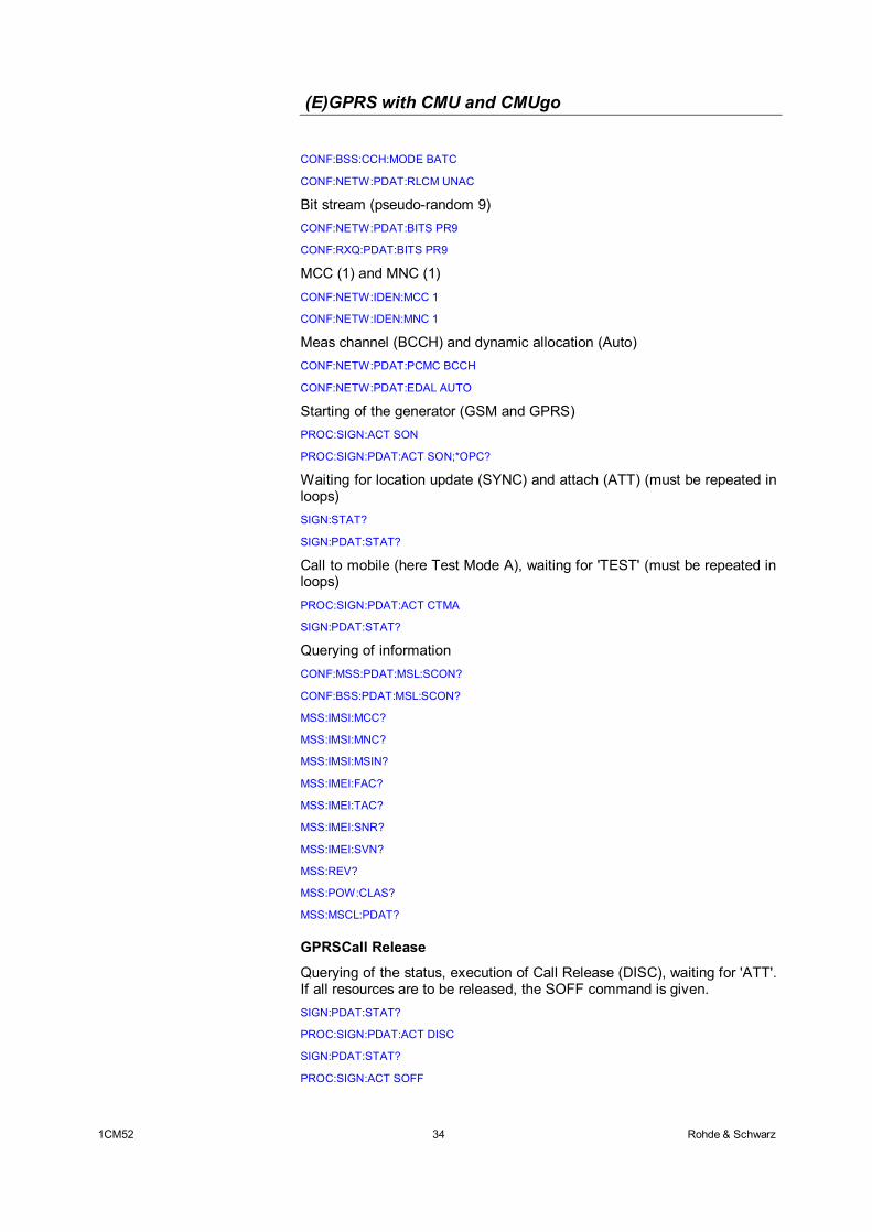
CONF:BSS:CCH:MODE BATC
CONF:NETW:PDAT:RLCM UNAC
Bit stream (pseudo-random 9) CONF:NETW:PDAT:BITS PR9
CONF:RXQ:PDAT:BITS PR9
MCC (1) and MNC (1) CONF:NETW:IDEN:MCC 1
CONF:NETW:IDEN:MNC 1
Meas channel (BCCH) and dynamic allocation (Auto) CONF:NETW:PDAT:PCMC BCCH
CONF:NETW:PDAT:EDAL AUTO
Starting of the generator (GSM and GPRS) PROC:SIGN:ACT SON
PROC:SIGN:PDAT:ACT SON;*OPC?
Waiting for location update (SYNC) and attach (ATT) (must be repeated in loops)
SIGN:STAT?
SIGN:PDAT:STAT?
Call to mobile (here Test Mode A), waiting for 'TEST' (must be repeated in loops)
PROC:SIGN:PDAT:ACT CTMA
SIGN:PDAT:STAT?
Querying of information
CONF:MSS:PDAT:MSL:SCON?
CONF:BSS:PDAT:MSL:SCON?
MSS:IMSI:MCC?
MSS:IMSI:MNC?
MSS:IMSI:MSIN?
MSS:IMEI:FAC?
MSS:IMEI:TAC?
MSS:IMEI:SNR?
MSS:IMEI:SVN?
MSS:REV?
MSS:POW:CLAS?
MSS:MSCL:PDAT?
GPRSCall Release
Querying of the status, execution of Call Release (DISC), waiting for 'ATT'. If all resources are to be released, the SOFF command is given. SIGN:PDAT:STAT?
PROC:SIGN:PDAT:ACT DISC
SIGN:PDAT:STAT?
PROC:SIGN:ACT SOFF
(E)GPRS with CMU and CMUgo
1CM52 35 Rohde & Schwarz
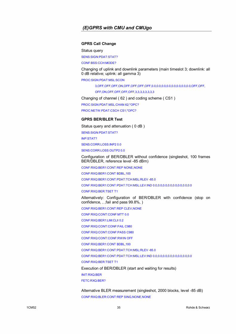
GPRS Call Change
Status query SENS:SIGN:PDAT:STAT?
CONF:BSS:CCH:MODE?
Changing of uplink and downlink parameters (main timeslot 3; downlink: all 0 dB relative; uplink: all gamma 3)
PROC:SIGN:PDAT:MSL:SCON
3,OFF,OFF,OFF,ON,OFF,OFF,OFF,OFF,0.0,0.0,0.0,0.0,0.0,0.0,0.0,0.0,OFF,OFF,
OFF,ON,OFF,OFF,OFF,OFF,3,3,3,3,3,3,3,3
Changing of channel ( 62 ) and coding scheme ( CS1 )
PROC:SIGN:PDAT:MSL:CHAN 62;*OPC?
PROC:NETW:PDAT:CSCH CS1;*OPC?
GPRS BER/BLER Test
Status query and attenuation ( 0 dB ) SENS:SIGN:PDAT:STAT?
INP:STAT?
SENS:CORR:LOSS:INP2 0.0
SENS:CORR:LOSS:OUTP2 0.0
Configuration of BER/DBLER without confidence (singleshot, 100 frames BER/DBLER, reference level -85 dBm) CONF:RXQ:BER1:CONT:REP NONE,NONE
CONF:RXQ:BER1:CONT BDBL,100
CONF:RXQ:BER1:CONT:PDAT:TCH:MSL:RLEV -85.0
CONF:RXQ:BER1:CONT:PDAT:TCH:MSL:LEV:IND 0.0,0.0,0.0,0.0,0.0,0.0,0.0,0.0
CONF:RXQ:BER:TSET T1
Alternatively: Configuration of BER/DBLER with confidence (stop on confidence, , ,fail and pass 99.8%, ) CONF:RXQ:BER1:CONT:REP CLEV,NONE
CONF:RXQ:CONT:CONF:MTT 0.0
CONF:RXQ:BER1:LIM:CLII 0.2
CONF:RXQ:CONT:CONF:FAIL C980
CONF:RXQ:CONT:CONF:PASS C980
CONF:RXQ:CONT:CONF:RWIN OFF
CONF:RXQ:BER1:CONT BDBL,100
CONF:RXQ:BER1:CONT:PDAT:TCH:MSL:RLEV -85.0
CONF:RXQ:BER1:CONT:PDAT:TCH:MSL:LEV:IND 0.0,0.0,0.0,0.0,0.0,0.0,0.0,0.0
CONF:RXQ:BER:TSET T1
Execution of BER/DBLER (start and waiting for results) INIT:RXQ:BER
FETC:RXQ:BER?
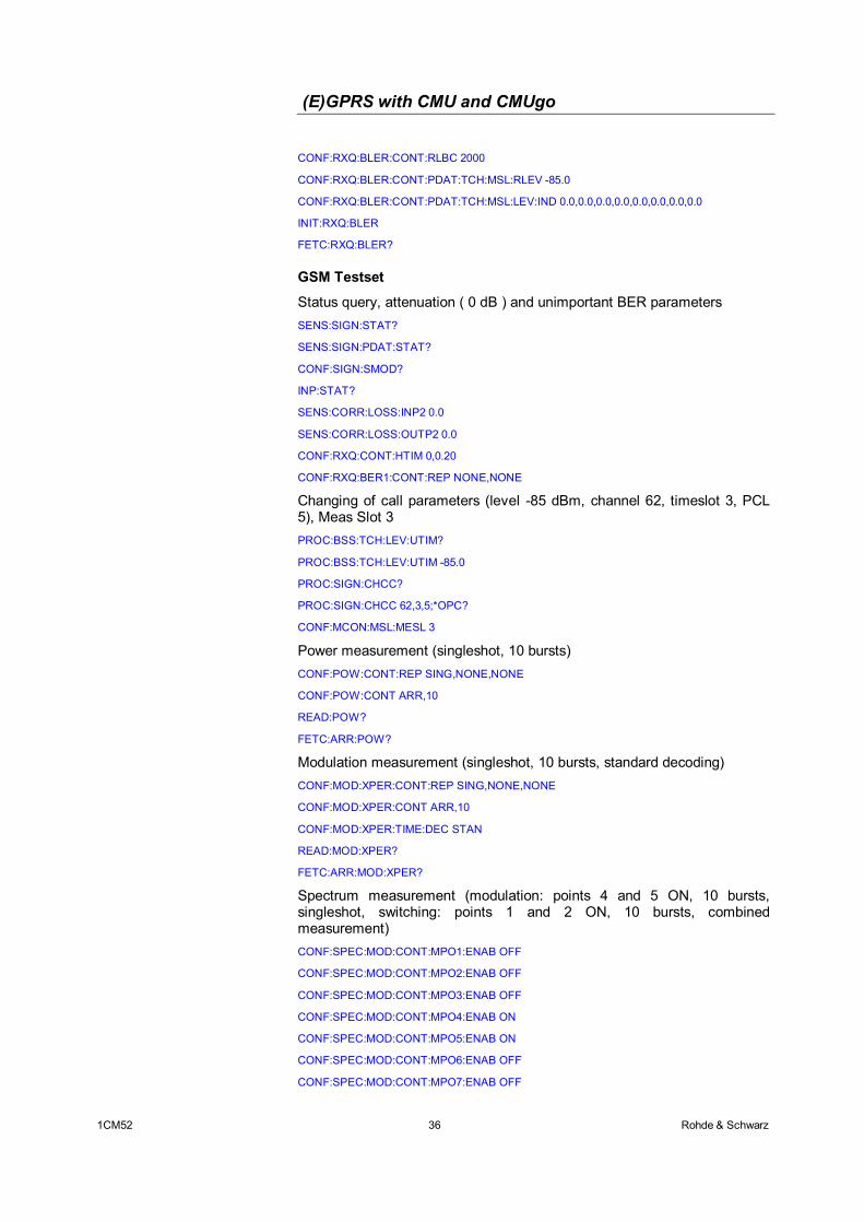
Alternative BLER measurement (singleshot, 2000 blocks, level -85 dB) CONF:RXQ:BLER:CONT:REP SING,NONE,NONE
(E)GPRS with CMU and CMUgo
1CM52 36 Rohde & Schwarz
CONF:RXQ:BLER:CONT:RLBC 2000
CONF:RXQ:BLER:CONT:PDAT:TCH:MSL:RLEV -85.0
CONF:RXQ:BLER:CONT:PDAT:TCH:MSL:LEV:IND 0.0,0.0,0.0,0.0,0.0,0.0,0.0,0.0
INIT:RXQ:BLER
FETC:RXQ:BLER?
GSM Testset
Status query, attenuation ( 0 dB ) and unimportant BER parameters SENS:SIGN:STAT?
SENS:SIGN:PDAT:STAT?
CONF:SIGN:SMOD?
INP:STAT?
SENS:CORR:LOSS:INP2 0.0
SENS:CORR:LOSS:OUTP2 0.0
CONF:RXQ:CONT:HTIM 0,0.20
CONF:RXQ:BER1:CONT:REP NONE,NONE
Changing of call parameters (level -85 dBm, channel 62, timeslot 3, PCL 5), Meas Slot 3
PROC:BSS:TCH:LEV:UTIM?
PROC:BSS:TCH:LEV:UTIM -85.0
PROC:SIGN:CHCC?
PROC:SIGN:CHCC 62,3,5;*OPC?
CONF:MCON:MSL:MESL 3
Power measurement (singleshot, 10 bursts)
CONF:POW:CONT:REP SING,NONE,NONE
CONF:POW:CONT ARR,10
READ:POW?
FETC:ARR:POW?
Modulation measurement (singleshot, 10 bursts, standard decoding)
CONF:MOD:XPER:CONT:REP SING,NONE,NONE
CONF:MOD:XPER:CONT ARR,10
CONF:MOD:XPER:TIME:DEC STAN
READ:MOD:XPER?
FETC:ARR:MOD:XPER?
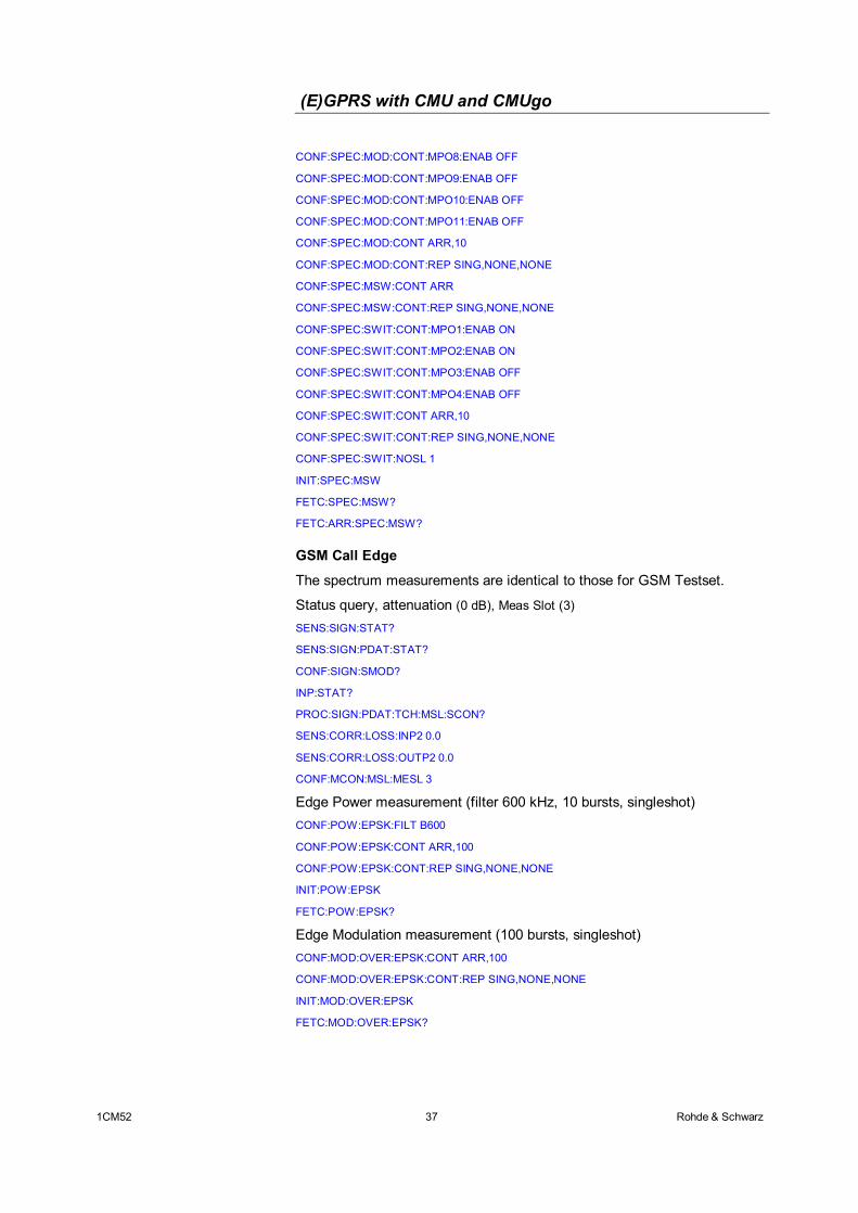
Spectrum measurement (modulation: points 4 and 5 ON, 10 bursts, singleshot, switching: points 1 and 2 ON, 10 bursts, combined measurement) CONF:SPEC:MOD:CONT:MPO1:ENAB OFF
CONF:SPEC:MOD:CONT:MPO2:ENAB OFF
CONF:SPEC:MOD:CONT:MPO3:ENAB OFF
CONF:SPEC:MOD:CONT:MPO4:ENAB ON
CONF:SPEC:MOD:CONT:MPO5:ENAB ON
CONF:SPEC:MOD:CONT:MPO6:ENAB OFF
CONF:SPEC:MOD:CONT:MPO7:ENAB OFF
(E)GPRS with CMU and CMUgo
1CM52 37 Rohde & Schwarz
CONF:SPEC:MOD:CONT:MPO8:ENAB OFF
CONF:SPEC:MOD:CONT:MPO9:ENAB OFF
CONF:SPEC:MOD:CONT:MPO10:ENAB OFF
CONF:SPEC:MOD:CONT:MPO11:ENAB OFF
CONF:SPEC:MOD:CONT ARR,10
CONF:SPEC:MOD:CONT:REP SING,NONE,NONE
CONF:SPEC:MSW:CONT ARR
CONF:SPEC:MSW:CONT:REP SING,NONE,NONE
CONF:SPEC:SWIT:CONT:MPO1:ENAB ON
CONF:SPEC:SWIT:CONT:MPO2:ENAB ON
CONF:SPEC:SWIT:CONT:MPO3:ENAB OFF
CONF:SPEC:SWIT:CONT:MPO4:ENAB OFF
CONF:SPEC:SWIT:CONT ARR,10
CONF:SPEC:SWIT:CONT:REP SING,NONE,NONE
CONF:SPEC:SWIT:NOSL 1
INIT:SPEC:MSW
FETC:SPEC:MSW?
FETC:ARR:SPEC:MSW?
GSM Call Edge
The spectrum measurements are identical to those for GSM Testset.
Status query, attenuation (0 dB), Meas Slot (3)
SENS:SIGN:STAT?
SENS:SIGN:PDAT:STAT?
CONF:SIGN:SMOD?
INP:STAT?
PROC:SIGN:PDAT:TCH:MSL:SCON?
SENS:CORR:LOSS:INP2 0.0
SENS:CORR:LOSS:OUTP2 0.0
CONF:MCON:MSL:MESL 3
Edge Power measurement (filter 600 kHz, 10 bursts, singleshot)
CONF:POW:EPSK:FILT B600
CONF:POW:EPSK:CONT ARR,100
CONF:POW:EPSK:CONT:REP SING,NONE,NONE
INIT:POW:EPSK
FETC:POW:EPSK?
Edge Modulation measurement (100 bursts, singleshot)
CONF:MOD:OVER:EPSK:CONT ARR,100
CONF:MOD:OVER:EPSK:CONT:REP SING,NONE,NONE
INIT:MOD:OVER:EPSK
FETC:MOD:OVER:EPSK?
(E)GPRS with CMU and CMUgo
1CM52 38 Rohde & Schwarz
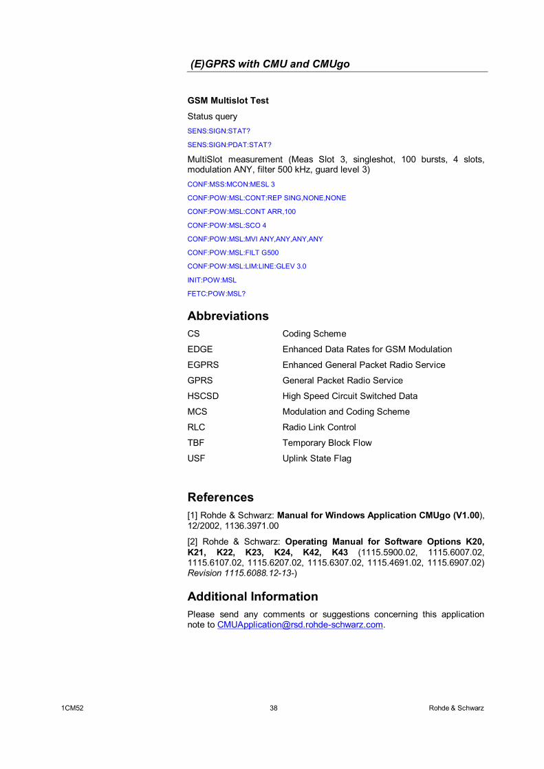
GSM Multislot Test
Status query SENS:SIGN:STAT?
SENS:SIGN:PDAT:STAT?
MultiSlot measurement (Meas Slot 3, singleshot, 100 bursts, 4 slots, modulation ANY, filter 500 kHz, guard level 3)
CONF:MSS:MCON:MESL 3
CONF:POW:MSL:CONT:REP SING,NONE,NONE
CONF:POW:MSL:CONT ARR,100
CONF:POW:MSL:SCO 4
CONF:POW:MSL:MVI ANY,ANY,ANY,ANY
CONF:POW:MSL:FILT G500
CONF:POW:MSL:LIM:LINE:GLEV 3.0
INIT:POW:MSL
FETC:POW:MSL?
Abbreviations CS Coding Scheme
EDGE Enhanced Data Rates for GSM Modulation
EGPRS Enhanced General Packet Radio Service
GPRS General Packet Radio Service
HSCSD High Speed Circuit Switched Data
MCS Modulation and Coding Scheme
RLC Radio Link Control
TBF Temporary Block Flow
USF Uplink State Flag
References [1] Rohde & Schwarz: Manual for Windows Application CMUgo (V1.00), 12/2002, 1136.3971.00
[2] Rohde & Schwarz: Operating Manual for Software Options K20, K21, K22, K23, K24, K42, K43 (1115.5900.02, 1115.6007.02, 1115.6107.02, 1115.6207.02, 1115.6307.02, 1115.4691.02, 1115.6907.02) Revision 1115.6088.12-13-)
Additional Information Please send any comments or suggestions concerning this application note to [email protected].
(E)GPRS with CMU and CMUgo
1CM52 39 Rohde & Schwarz
Ordering Information Communication Tester R&S CMU200 1100.0008.02 CMU-B21(1) Versatile signalling unit 1100.5200.02 CMU-B21v14(1) Universal signalling unit 1100.5200.14 Option B41 (optional) Audio generator and analyzer 1100.5300.02 CMU-K20 SW options for GSM400 1115.5900.02 CMU-K21 SW options for GSM900 1115.6007.02 CMU-K22 SW options for GSM1800 1115.6107.02 CMU-K23 SW options for GSM1900 1115.6207.02 CMU-K24 SW options for GSM850 1115.6307.02 CMU-K42 SW GPRS extension for GSM 1115.4691.02 CMU-K43 SW EGPRS extension for GSM 1115.6907.02
(1) CMU-B21 or CMU-B21v14 with CMU-B54v14 is required.
ROHDE & SCHWARZ GmbH & Co. KG . Mühldorfstraße 15 . D-81671 München . Postfach 80 14 69 . D-81614 München . Tel
(089) 4129 -0 . Fax (089) 4129 - 13777 . Internet: http://www.rohde-schwarz.com
This application note and the supplied programs may only be used subject to observance of the conditions of use set forth in the download area of the Rohde & Schwarz website.