Embed Size (px)
Citation preview
1
Discrete Event Control
Concept
Representation
DEC controller design
DEC controller implementation

2
DEC controller implementation
Hard wired systems inflexible software systems
computer-based system
Electric Ladder Logic Systems or Diagrams
Soft Ladder Logic Systems or Diagrams
High level logic systems and programming codes
3
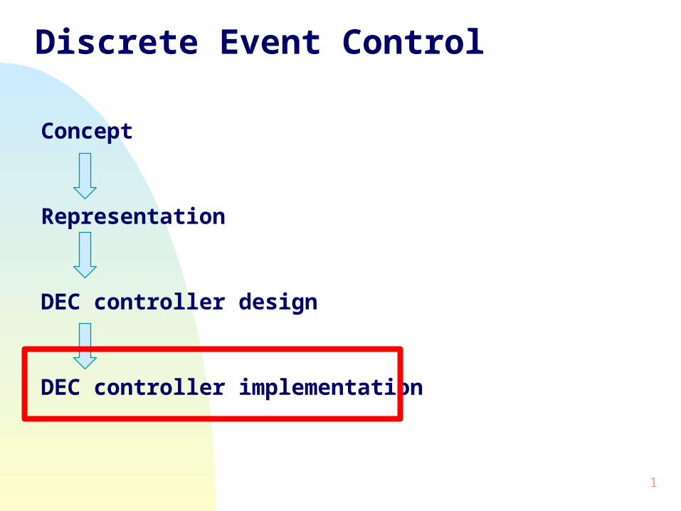
Electrical Ladder Logic Diagrams
Using switch to control a lightL: L=1 (light on) L=0 (light off)S: S=1 (switch on) S=0 (switch off)
Electric Ladder Logical Diagram is as follow (Fig.1):
Figure 1
4
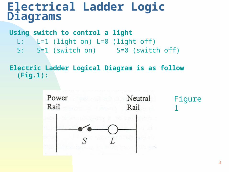
Electrical Ladder Logic Diagrams (ELLD)
The structure of ELLD is:
- left rail with power -> power rail
- right rail with neutral -> neutral rail
- one path called “rung”
It is clear with the notation on Fig.1, when L=1 if and only if S=1 and when L=0 if and only if S=0
So this ELLD is a physical representation of the Boolean logic equation
L=S

5
Electrical Ladder Logic Diagrams
Fig.2 shows a multiple rungs (two rungs).
The problem:
- Two lights, L1 and L2.
- Three switches, S1, S2, S3
Fig.2 physically represents:
L1=S1+S2 (Rung 1)
L2=S2S3 (Rung 2)
When S1 or S2 is on, L1 is on
When both S2 and S3 are on, L2 is on.

6
Electrical Ladder Logic Diagrams
Control Relays:
Instead of using one switch to control one light or object, a generic component of hardwired control implementation is a control relay, see Fig.3. Features of a control relay:
1.Coil, normally closed (n.c.) contacts, and normally open contacts (n.o.).
2.If there is a current in the coil, the coil is energized, then n.c. will open and n.o. will close.

7
Electrical Ladder Logic Diagrams
CR is represented by a circle, as an object.
n.o. contact n.c. contact
Fig. 3

8
Electrical Ladder Logic Diagrams
Figure 4 shows an example.
- when S is open, L1 is off, L2 is on
- when S is closed, L1 is on, L2 is off.
Figure 4

9
Electrical Ladder Logic Diagrams
The Boolean logic equations for the rungs in the ladder diagram are:
Rung 1: CR=S
Rung 2: L1=CR
Rung 3: L2=CR
Note here that nc is denoted by CR
Combining the equations for the rungs yields
L1=S
L2=S
10
Electrical Ladder Logic Diagrams
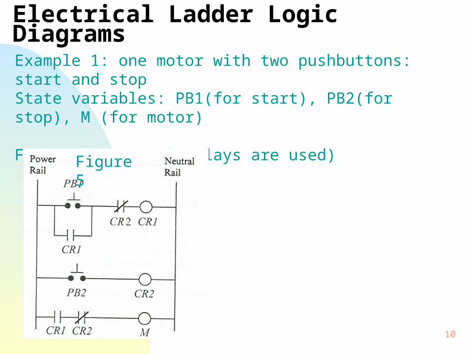
Example 1: one motor with two pushbuttons: start and stopState variables: PB1(for start), PB2(for stop), M (for motor)
Figure 5 (control relays are used)
Figure 5

11
Electrical Ladder Logic Diagrams
From Figure 5, we know:
PB1 is on -> CR1 energized, no1 is closed -> M=1
PB2 is on -> CR2 energized, nc2 is open -> M=0
Rung 1: CR1=(PB1+CR1) CR2
Rung 2: CR2=(PB2)
Rung 3: M=CR1 CR2

12
Electrical Ladder Logic Diagrams
Finally, M=(PB1+CR1)(PB2)(PB2)=(PB1+CR1)PB2
Contact CR1 may be omitted here if the switch here is “permanent”. When the switch is momentary (i.e., the switch will momentarily close and then be back to unclose state), we need CR1. This is because otherwise, there will be no power on rung 1 shortly after PB1 is pressed. The role of CR1 is to keep the power through on the rung even though PB1 is shortly back to unclose state. Such a role of CR1 is called “latching”.

13
Software Ladder Logic Diagrams
General idea:
Electric Ladder Diagram
Switch
Button
Coil
Relay
Two states: on, off
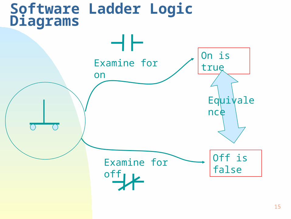
Examine for on
Examine for off

14
Software Ladder Logic Diagrams
Examine for onExamine for off
An input device
Viewpoint
15
Software Ladder Logic Diagrams
Examine for onOn is true
Examine for off Off is false
Equivalence


![DISCRETE-TIME PI CONTROLLER BASED SPEED CONTROL OF … · following controllers are used: fuzzy logic controller (FLC) [15], self-tuning PI controllers [16], sliding mode control](https://img.pdfslide.net/doc/110x75/5ff9aa4aae70605aac1dd19d/discrete-time-pi-controller-based-speed-control-of-following-controllers-are-used.jpg)


![Caterpillar: ﺭﻮﺗﺍﺮﻧژ Caterpillar : ﻝﺰﻳﺩ ﺭﻮﺗﻮﻣ · 2017. 12. 12. · • EMCP 4.2 Genset Controller [ ] Local & remote annunciator modules [ ] Discrete](https://img.pdfslide.net/doc/110x75/608eb4d90bbcc85d9f517f92/caterpillar-iiiiii-caterpillar-iiii-iiiii-2017.jpg)