Embed Size (px)
Citation preview
RATE GYRO ASSEMBLY ASSEMBLY
/PARTIAL ABORT SENSOR NAVIGATION MEASUREMENT PULSE TORQUE
UNIT ASSEMBLY SASE
CDR'S THRUST/ TRANSLATION CONTROLLER
ASSEMBLY
SAC CONTROL ASSEMBLY
NO. 3
GIMBAL DRIVE
ACTUATORS A.1111:110441
ALIGNMENT OPTICAL
TELESCOPE
SAC CONTROL ASSEMBLIES
NO. I AND 2
DATA ENTRY AND DISPLAY
ASSEMBLY
LMPS ATTITUDE CONTROL'S
ASSEMBLY
LAWS THRUST/ . TRANSLATION
CONTROLLER ASSEMBLY
DISPLAY AND KEYBOARD ASSEMBLY
COWS ATTITUDE CONTROLLER
ASSEMBLY
ABORT ELECTRONICS ASSEMBLY
ATTITUDE AND TRANSLATION CONTROL ASSEMBLY
LM GUIDANCE COMPUTER
COUPLING DATA UNIT
POWER AND servo ASSEMBLY
SIGNAL CONDITIONS ASSEMBLY
DOOM wow CONTROL ASS&BLY
LMA790- 3- LM APOLLO OPERATIONS HANDBOOK
SUBSYSTEMS DATA
2. 1 GUIDANCE, NAVIGATION, AND CONTROL SUBSYSTEM.
2. 1. 1 INTRODUCTION.
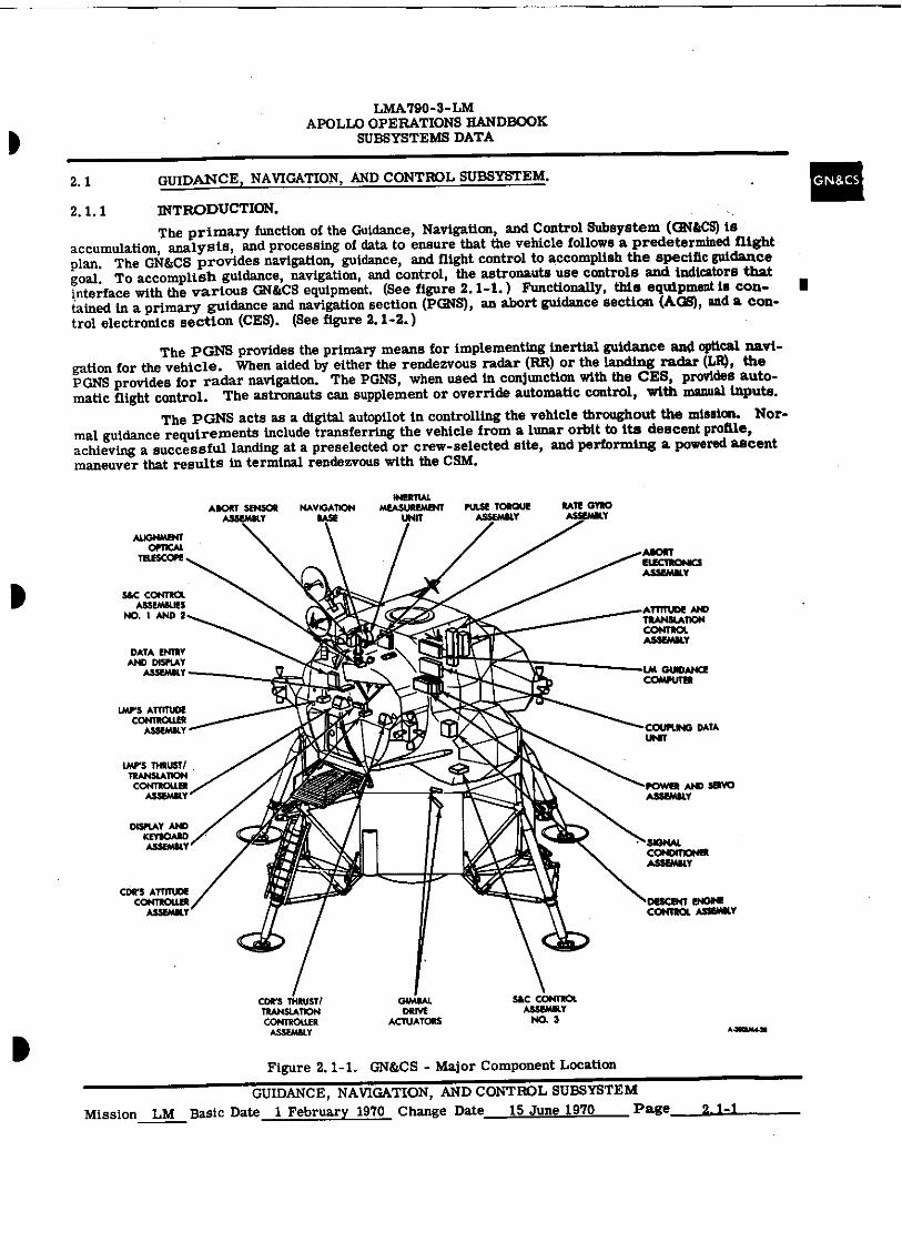
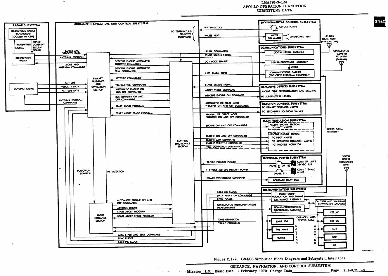
The primary function of the Guidance, Navigation, and Control Subsystem (GN&CS) is accumulation, analysis, and processing of data to ensure that the vehicle follows a predetermined flight plan. The GN&CS provides navigation, guidance, and flight control to accomplish the specific guidance goal. To accomplish guidance, navigation, and control, the astronauts use controls and indicators that interface with the various GN&CS equipment. (See figure 2.1-1.) Functionally, this equipment is con- I tamed in a primary guidance and navigation section (PGNS), an abort guidance section (AGS), and a con- trol electronics section (CES). (See figure 2.1-2.)
The PGNS provides the primary means for implementing inertial guidance and optical navi-gation for the vehicle. When aided by either the rendezvous radar (RR) or the landing radar (LR), the PGNS provides for radar navigation. The PGNS, when used in conjunction with the CES, provides auto-matic flight control. The astronauts can supplement or override automatic control, with manual inputs.
The PGNS acts as a digital autopilot in controlling the vehicle throughout the mission. Nor-mal guidance requirements include transferring the vehicle from a lunar orbit to its descent profile, achieving a successful landing at a preselected or crew-selected site, and performing a powered ascent maneuver that results in terminal rendezvous with the CSM.
Figure 2. 1-1. GN&CS - Major Component Location
GUIDANCE, NAVIGATION, AND CONTROL SUBSYSTEM Mission LM Basic Date 1 February 1970 Change Date 15 June 1970 Page 2.1-i
LMA790-3- LM APOLLO OPERATIONS HANDBOOK
SUBSYSTEMS DATA
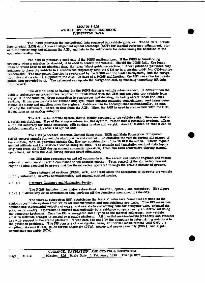
The PGNS provides the navigational data required for vehicle guidance. These data include line-of-sight (LOS) data from an alignment optical telescope (AOT) for inertial reference alignment, sig-nals for initializing and aligning the AGS, and data to the astronauts for determining the location of the computed landing site.
The AGS is primarily used only if the PGNS malfunctions. If the PGNS is functioning properly when a mission is aborted, it is used to control the vehicle. Should the PGNS fail, the lunar mission would have to be aborted; thus, the term "abort guidance section. " Abort guidance provides only guidance to place the vehicle in a rendezvous trajectory with the CSM or in a parking orbit for GSM-active rendezvous. The navigation function is performed by the PUNS and the Radar Subsystem, but the naviga-tion information also is supplied to the AGS. In case of a PGNS malfunction, the AGS uses the last navi-gation data provided to it. The astronaut can update the navigation data by manually inserting RR data into the AGS.
The AGS is used as backup for the PGNS during a vehicle mission abort. It determines the vehicle trajectory or trajectories required for rendezvous with the CSM and can guide the vehicle from any point in the mission, from separation to rendezvous and docking, including ascent from the lunar surface. It can provide data for attitude displays, make explicit guidance computations, and issue com-mands for firing and shutting down the engines. Guidance can be accomplished automatically, or man-ually by the astronauts, based on data from the AGS. When the AGS is used in conjunction with the CES, it functions as an analog autopilot.
The AGS is an inertial system that is rigidly strapped to the vehicle rather than mounted on a stabilized platform. Use of the strapped-down inertial system, rather than a gimbaled. system, offers sufficient accuracy for lunar missions, with savings in size and weight. Another feature is that it can be updated manually with radar and optical aids.
The CES processes Reaction Control Subsystem (RCS) and Main Propulsion Subsystem (MPS) control signals for vehicle stabilization and control. To stabilize the vehicle during all phases of the mission, the CES provides signals that fire any combination of the 16 RCS thrusters. These signals control attitude and translation about or along all axes. The attitude and translation control data inputs originate from the PGNS during normal automatic operation, from two hand controllers during manual operations, or from the AGS during certain abort situations.
The CES also processes on and off commands for the ascent and descent engines and routes automatic and manual throttle commands to the descent engine. Trim control of the gimbaled descent engine is also provided to assure that the thrust vector operates through the vehicle center of gravity.
These integrated sections (PGNS, AGS, and CES) allow the astronauts to operate the vehicle in fully automatic, several semiautomatic, and manual control modes.
2.1.1. 1 Primary Guidance and Navigation Section.
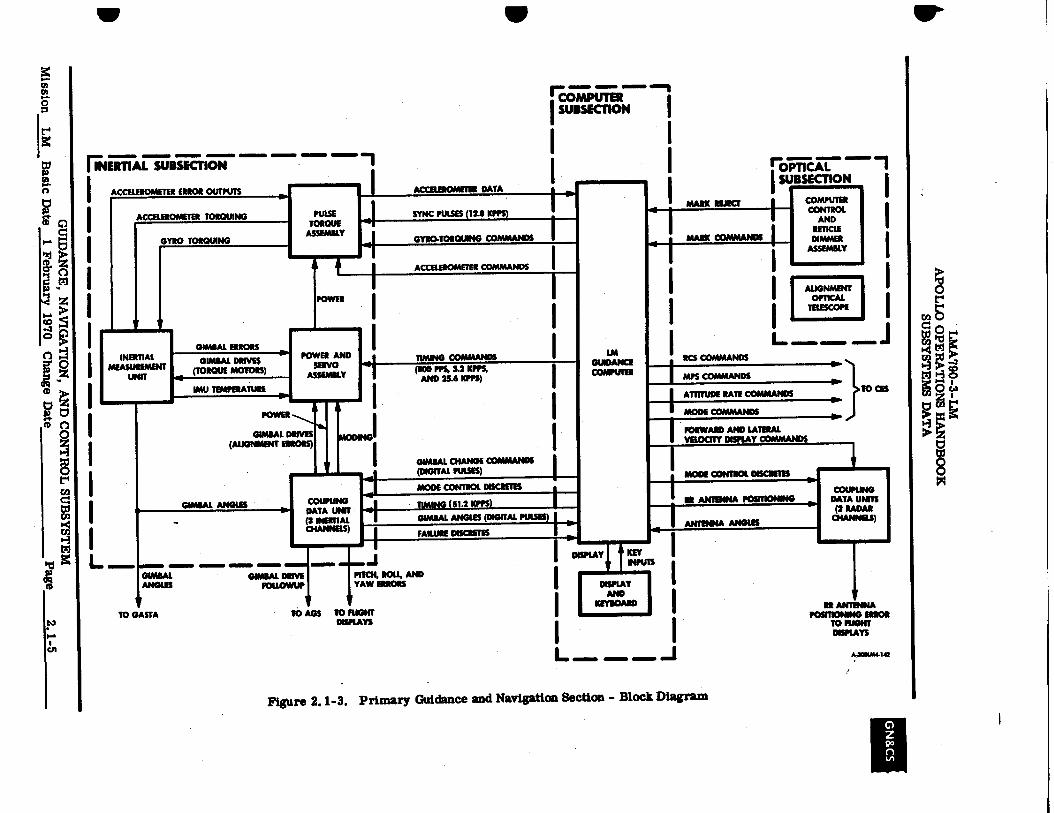
The PGNS includes three major subsections: inertial, optical, and computer. (See figure 2.1-3.) Individually or in combination they perform all the functions mentioned previously.
The inertial subsection (ISS) establishes the inertial reference frame that is used as the central coordinate system from which all measurements and computations are made. The ISS measures attitude and incremental velocity changes, and assists in converting data for computer use, onboard dis-play, or telemetry. Operation is started automatically by a guidance computer or by an astronaut using the computer keyboard. Once the ISS is energized and aligned to the inertial reference, any vehicle rotation (attitude change) is sensed by a stable platform. All inertial measurements (velocity and attitude) are with respect to the stable platform. These data are used by the computer in dete,rmining solutions to the guidance problems. The ISS consists of a navigation base, an inertial measurement unit (IMU), a coupling data unit (CDU), pulse torque assembly (PTA), power and servo assembly (PSA), and signal conditioner assembly (SCA).
•
GUIDANCE, NAVIGATION, AND CONTROL SUBSYSTEM Page 2.1-2 Mission LM Basic Date 1 February 1970 Change Date
WATER-GLYCOL
WASTE HEAT
UPLINK COMMANDS
STAGE STATUS SIGNAL
DC (VOICE ENABLE)
1-KC ALARM TONE
STAGE STATUS SIGNAL
ABORT STAGE COMMAND
DESCENT ENGINE-ON COMMAND
AUTOMATIC OR PULSE MODE THRUSTER ON AND OFF COMMANDS
MANUAL OR DIRECT MODE THRUSTER ON AND OFF COMMANDS
ENGINE ON AND OFF COMMANDS
ENGINE ON AND OFF COMMANDS
ENGINE ARM COMMAND ENGINE THROTTLE COMMANDS
TRIM COMMANDS (MECHANICAL)
28-VDC PRIMARY POWER
113-VOLT 400-CPS PRIMARY POWER
CONTROL ELECTRONICS
SECTION
DESCENT ENGINE AUTOMATIC THROTTLE COMMANDS
DESCENT ENGINE AUTOMATIC TRIM COMMANDS
MODE AND ANTENNA COMMANDS
TRANSLATION COMMANDS VELOCITY DATA ■•••■
ALTITUDE RATE
ALTITUDE
PRIMARY GUIDANCE
AND NAVIGATION
SECTION AUTOMATIC ENGINE ON AND OFF COMMANDS
ATTITUDE COMMANDS
ANTENNA POSITION COMMANDS
KS THRUSTER ON AND OFF COMMANDS
START ABORT PROGRAM
START ABORT STAGE PROGRAM
GUIDANCE, NAVIGATION, AND CONTROL SUBSYSTEM
RANGE AND VELOCITY DATA
ANTENNA POSITION
TO TEMPERATURE-SENSITIVE
EQUIPMENT
RADAR SUBSYSTEM
RENDEZVOUS RADAR TRANSPONDER
(LOCATED IN CSM)
PHASE- TRANSMITTED COHERENT SIGNAL RETURN
1,, SIGNAL
RENDEZVOUS RADAR
LANDING RADAR
FOLLOWUP SIGNALS-
INITIALIZATION
1 C W
LIE A U
A 8.-s.rnGS R
I N ... I I N.4
N
DATA START AND STOP COMMANDS
SYNC PULSES
1.024-MC CLOCK HEATER
G
LMA790-3- LM APOLLO OPERATIONS HANDBOOK
SUBSYSTEMS DATA
ENVIRONMENTAL CONTROL SUBSYSTEM
GLYCOL PUMPS
WATER SUBUMATOR OVERBOARD VENT
COMMUNICATIONS SUBSYSTEM
DIGITAL UPLINK ASSEMBLY
SIGNAL-PROCESSOR ASSEMBLY
VOICE
COMMUNICATIONS CARRIER (11 /0 CREW PERSONAL EQUIPMENT)
EXPLOSIVE DEVICES SUBSYSTEM
ASCENT TANK PRESSURIZATION AND STAGING
TO SUPERCRITICAL HELIUM
REACTION CONTROL SUBSYSTEM TO PRIMARY SOLENOID VALVES
TO SECONDARY SOLENOID VALVES
MAIN PROPULSION SUBSYSTEM NASCENT ENGINE SECTION
L TO PILOT VALVES J
ITESCENT ENGINE SECTION -1 '01 TQ PILOT VALVES I Pi TO ACTUATOR ISOLATION VALVES I F- TO THROTTLE ACTUATOR I _
UPLINKS FROM MSFN
(VHF AND UHF)
ELECTRICAL POWER SUBSYSTEM
O )) Al CDR'S OR LIP'S
(PANEL 11 OR 16) 28-VDC BUS
0 CDR'S 113-VAC -):,_141
(PANEL 11) RUSES
POWER SWITCHOVER COMMAND DEADFACE RELAY BOX
•
y OPERATIONAL TELEMETRY TO MSFN (S-BAND)
OPERATIONAL TELEMETRY
DIGITAL UPLINK
COMMANDS (UHF)
V
INSTRUMENTATION SUBSYSTEM
.....ICAUTION AND WARNING,' ELECTRONICS ASSEMIX
• 6-41 CES AC
OUT - OF - LIMITS STATUS DATA CES DC
PULSE - CODE MODULATION AND TIMING
ELECTRONICS ASSEMBLY
SIGNAL-CONDITIONING ELECTRONICS ASSEMBLY
RNDZ RD*
AUTOMATIC ENGINE ON AND OFF COMMANDS
ATTITUDE ERRORS
1.024-MC CLOCK
DATA AND STOP COMMANDS SYNC PULSES
OPERATIONAL INSTRUMENTATION MEASUREMENTS
ABORT GUIDANCE
SECTION
START ABORT PROGRAM
START ABORT STAGE PROGRAM
TONE GENERATOR
ENABLE COMMAND
0-300041-219
Figure 2.1-2. GN&CS Simplified Block Diagram and Subsystem Interfaces
GUIDANCE, NAVIGATION, AND CONTROL SUBSYSTEM Mission LM Basic Date 1 February 1970 Change Date Page 2.1-3/2.1-4
rOPTICAL
I SUBSECTION I
COMPUTER CONTROL
AND RETICLE DIMMER
ASSEMBLY
ALIGNMENT OPTICAL
TELESCOPE
M111111=11, 411■11•11
Mn Tn
w
,...
IUD LT 0
• Z 1.+
0
i
•
) tt
0 Oz
8
• X
01
rCOTAPirell7" SUBSECTION
FNETITAL sinulaST
I ACCELEROMETER ERROR OUTPUTS pin. .11
ACCELEROMETER TORQUING TORQUE
GYRO TORQUING ASSEMBLY
POWER
GIMBAL ANGLES
INERTIAL MEASUREMENT
UNIT
1 TO GASTA
.1.■ arm. ammo am. GIMBAL ANGUS
GIMBAL DRIVES (TORQUE MOTORS)
IMU TEMPERATURE 4■17.7r
POLDER
GIMBAL ERRORS - OP
GIMBAL DRIVES (AUGNMENT EIROPS)
GIMBAL DRIVE FOILOWUP
To AGS
POWER AND SERVO
ASSEMBLY
COUPLING DATA UNIT (3 INERTIAL CHANNELS)
I
SYNC PULSES (12.8 KPPS)
moo PPS, 3.2 ICPPS, AND 25.6 RIPS)
GYRO•IOW:IMMO COMMANDS
GIMBAL CHANGE COMMANDS (DIGITAL PULSES)
ACCELEROAIEUR DATA
TIMING (51.2 KPPS)
TIMING COMMANDS
MODE CONTROL DISCRETES
GIMBAL ANGLES (DIGITAL PULSES)
FAILURE DIORITES
CCEUEROMETElt
DISPLAY
LM
IMODE CONTROL DISMISS
IR ANTENNA POSITIONING
I ANTENNA ANGLES
I
MARK MUECT
COMMANDS
RCS COMMANDS
MPS COMMANDS
ATTITUDE RATE COMMANDS
FORWARD AND LATERAL VELOCITY DISPLAY COMMANDS
MODE COMMANDS
COUPUNG DATA UNITS
(2 RADAR CMANNELS)
►
}
411.
TO CES
PITCH, AND ROU.. YAW ERRORS
DISPLAY AND
ICEMAN
TO RIGHT OISPIAYS
RR ANTENNA POSITIONING NDOR
TO FLIGHT DISPLAYS
A4114/1414 L
Figure 2.1-3. Primary Guidance and Navigation Section - Block Diagram
LMA790-3-LM APOLLO OPERATIONS HANDBOOK
SUBSYSTEMS DATA
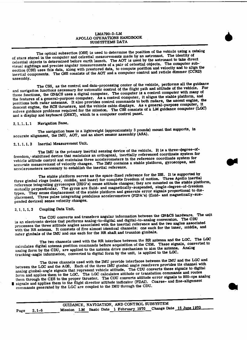
The optical subsection (OSS) is used to determine the position of the vehicle using a catalog of stars stored in the computer and celestial measurements made by an astronaut. The identity of celestial objects is determined before earth launch. The AOT is used by the astronaut to take direct visual sightings and precise angular measurements of a pair of celestial objects. The computer sub-section (CSS) uses this data, along with prestored data, to compute position and velocity and to align the inertial components. The OSS consists of the AOT and a computer control and reticle dimmer (CCRD) assembly.
The CSS, as the control and data-processing center of the vehicle, performs all the guidance and navigation functions necessary for automatic control of the flight path and attitude of the vehicle. For these functions, the GN&CS uses a digital computer. The computer is a control computer with many of the features of a general-purpose computer. As a control computer, it aligns the stable platform, and positions both radar antennas. It also provides control commands to both radars, the ascent engine, the descent engine, the RCS thrusters, and the vehicle cabin displays. As a general-purpose computer, it solves guidance problems required for the mission. The CSS consists of a LM guidance computer (LGC) and a display and keyboard (DSKY), which is a computer control panel.
2.1.1.1.1 Navigation Base.
The navigation base is a lightweight (approximately 3 pounds) mount that supports, in accurate alignment, the IMU , AOT, and an abort sensor assembly (ASA).
2.1.1.1.2 Inertial Measurement Unit.
The IMU is the primary inertial sensing device of the vehicle. It is a three-degree-of-freedom, ,, stabilized device that maintains an orthogonal, inertially referenced coordinate system for vehicle attitude control and maintains three accelerometers in the reference coordinate system for accurate measurement of velocity changes. The IMU contains a stable platform, gyroscopes, and accelerometers necessary to establish the inertial reference.
The stable platform serves as the space-fixed reference for the ISS. It is supported by three gimbal rings (outer, middle, and inner) for complete freedom of motion. Three Apollo inertial reference integrating gyroscopes (IRIG's) sense attitude changes; they are mounted on the stable platform, mutually perpendicular. The gyros are fluid- and magnetically-suspended, single-degree-of-freedom types. They sense displacement of the stable platform and generate error signals proportional to dis-placement. Three pulse integrating pendulous accelerometers (PIPA's) (fluid- and magnetically-sus-pended devices) sense velocity •changes.
2.1.1.1.3 Coupling Data Unit.
The CDU converts and transfers angular information between the GN&CS hardware. The unit is an electronic device that performs analog-to-digital and digital-to-analog conversion. The CDU processes the three attitude angles associated with the inertial reference and the two angles associated with the RR antenna. It consists of five almost identical channels: one each for the inner, middle, and outer gimbals of the IMU and one each for the RR shaft. and trunnion gimbals.
The two channels used with the RR interface between the RR antenna and the LGC. The LGC calculates digital antenna position commands before acquisition of the CSM. These signals, converted to analog form by the CDU, are applied to the antenna drive mechanism to aim the antenna. Analog tracking-angle information, converted to digital form by the unit, is applied to the LGC.
The three channels used with the IMU provide interfaces between the IMU and the LGC and between the LGC and the AGS. Each of the three IMU gimbal angle resolvers provides its channel with analog gimbal-angle signals that represent vehicle attitude. The CDU converts these signals to digital form and applies them to the LGC. The LGC calculates attitude or translation commands and routes them through the CES to the proper thruster. The CDU converts attitude error signals to 800-cps analog
■ signals and applies them to the flight director attitude indicator (FDAI). Coarse- and fine-alignment commands generated by the LGC are coupled to the IMU through the CDU.
GUIDANCE, NAVIGATION, AND CONTROL SUBSYSTEM Page 2.1-6 Mission LM Basic Date 1 February 1970 Change Date 15 June 1970

LMA790-3-411 APOLLO OPERAMNDBOOK
SUl3SYSTE1111111TA
2. 1. 1. 1. 4 Pulse Torque Assembly.
The PTA supplies inputs to, and processermtputs from, the inertial components in the IN.
2.1.1.1. 5 Power and Servo Assembly.
The PSA contains power supplies for gemellse of internal power required by the PONS, and servomechanisms and temperature control circa) fir the IMU.
2. 1. 1. 1. 6 Signal Conditioner Assembly.
The SCA provides an interface between Ikencte3 and the Instrumentation Subsystem (IS). The SCA preconditions PGNS measurements to a 0- to Ewalt d-c format before the signals are routed to the IS.
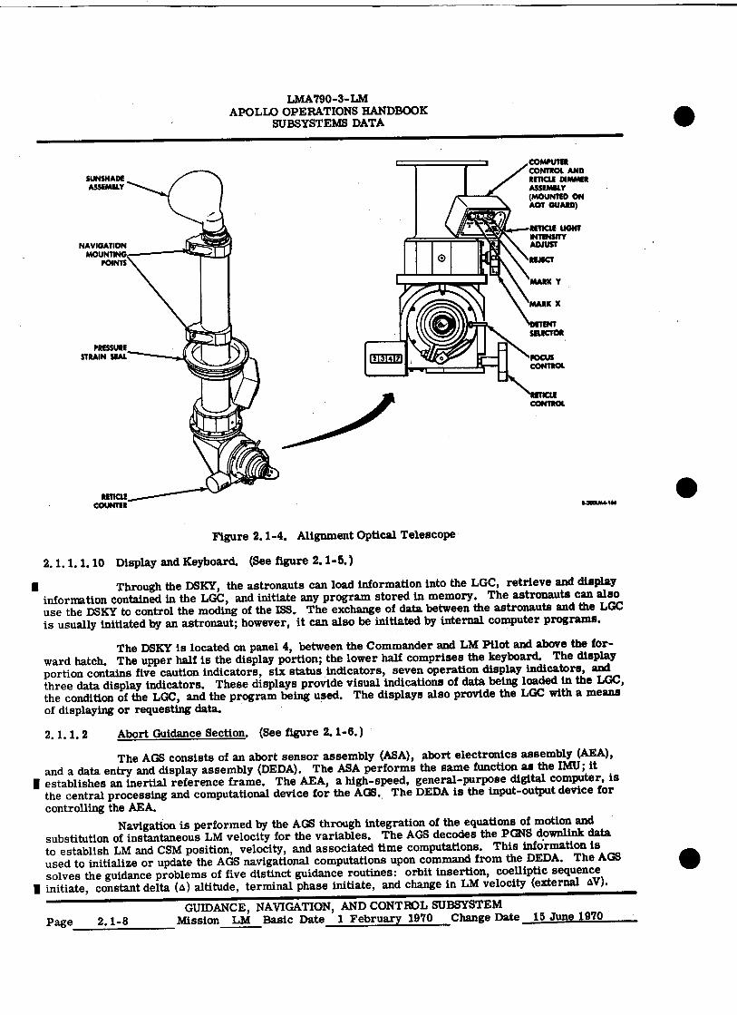
2. 1. 1. 1. 7 Alignment Optical Telescope. (See figeee3L1 ,-4.)
The AOT, an L-shaped periscope, is umiak the astronaut to take angular measurements of celestial objects. These angular measurements are relpised for orienting the platform during certain periods while the vehicle is in flight and during pre"- preparations while an the lunar surface. Sightings taken with the AOT are transferred to the Ligrig the astronaut, using the CCRD assembly. This assembly also controls the brightness of the telesseps reticle pattern.
2.1.1. 1. 8 Computer Control and Reticle Dimmer Amenably. Wee figure 2.1-5.)
The CCRD assembly is mounted on an Ant ward. The MARK X and MARE Y pushbuttons are used by the astronauts to semi discrete signals to the 111111:when star sightings are made. The REJECT pushbutton is used if an invalid mark has been sent tsar LGC. A thumbwheel on the assembly adjusts the brightness of the telescope reticle lamps.
2. 1. 1. I.9 LM Guidance Ciemputer.
The LGC is the central data-processinvielfee of the GN&CS. The LGC, a control computer with many of the features of ,a general-purpose compels% processes data and issues discrete control sig-nals for various subsystems. As a control computer, Maligns the IMU stable platform and provides RR antenna drive commands. The LGC also provides cambetcommands to the LR and RR, the ascent and descent engines, the RCS thrusters, and the cabin dimes. As a general-purpose computer, it solves guidance problems required for the mission. In midis, the LGC monitors the operation of the PGNS.
The LGC stores data pertinent to the aossiand descent flight profiles that the vehicle must assume to complete its mission. These data (positiss, velocity, and trajectory information) are used by the LGC to solve flight equations. The results of varion equations are used to determine the required magnitude and direction of thrust. The LGC establiskssoarrections to be made. The vehicle engines are turned on at the correct time, and steering commandeme controlled by the LGC to orient the vehicle to a new trajectory, if required. The MS senses acceleralimand supplies velocity changes, to the LGC, for calculating total velocity. Drive signals are supplied the LGC to the CDU and stabilization gyros in the ISS to align the gimbal angles in the IMU. Position Minas are supplied to the LGC to indicate attitude changes.
The LGC provides antenna-positioning ellipsis to the RR and receives, from the RR channels of the CDU, antenna angle information. The LGC unsafe information in the antenna-positioning calcula-tions. During lunar-landing operations, star-sightiougMermation is manually loaded into the LGC, using the DSKY. This information is used to calculate MI alfgetnent commands. The LGC and its programming help meet the functional requirements of the missies. i1e functions performed in the various mission phases include automatic and semiautomatic operatiam est are implemented mostly through the execution of the programs stored in the LGC memory.
GUIDANCE, NAVIGATION, INISCONTROL SUBSYSTEM Mission LM Basic Date 1 February 1970 Chasse See 15 June 1970 Page 2. 1-7
REJECT
MARK Y
MARK X
SELECTOR PRESSURE
STRAIN SEAL
116100044, 11111
COMPUTER CONTROL AND RETICLE DIMMER ASSEMBLY (MOUNTED ON AO/ GUARD)
arnal UGHT INTENSITY ADJUST
SUNSHADE ASSEMBLY
NAVIGATION MOUNTING
POINTS
LMA790-3-LM APOLLO OPERATIONS HANDBOOK
SUBSYSTEMS DATA
Figure 2.1-4. Alignment Optical Telescope
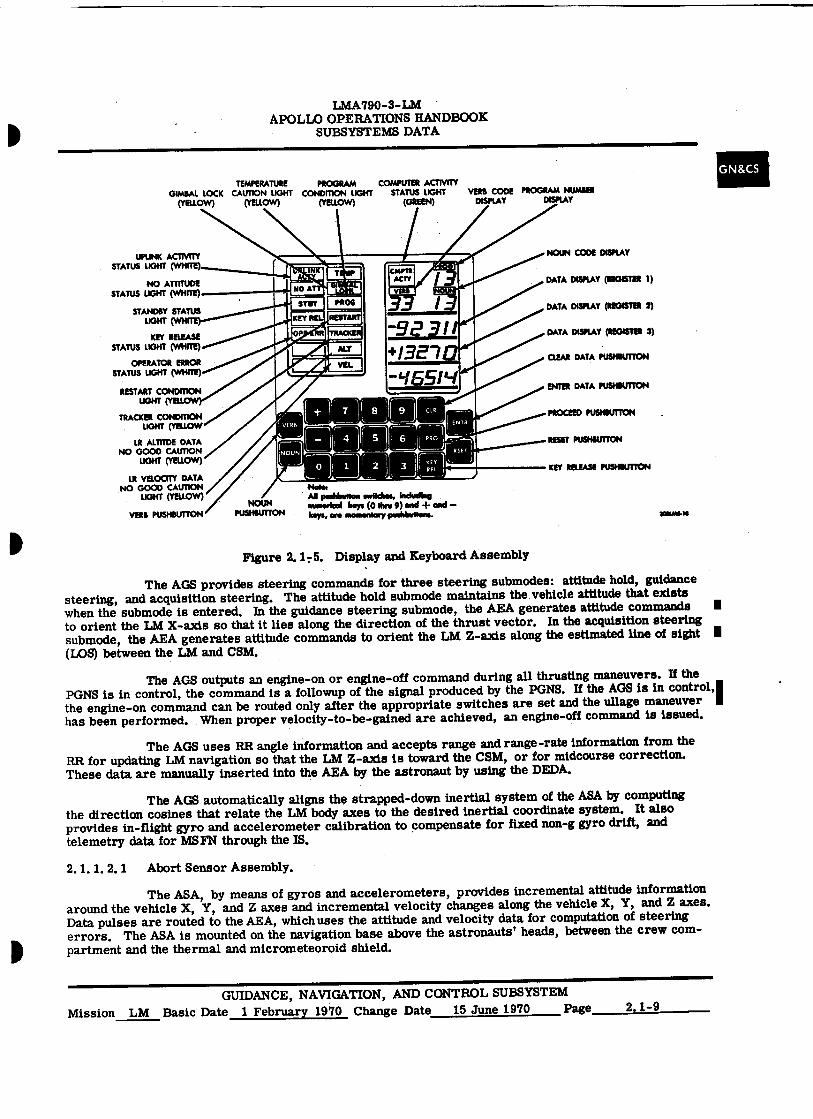
2.1.1.1.10 Display and Keyboard. (See figure 2.1-5.)
■ Through the DSKY, the astronauts can load information into the LGC, retrieve and display information contained in the LGC, and initiate any program stored in memory. The astronauts can also use the DSKY to control the moding of the 1SS. The exchange of data between the astronauts and the LGC is usually initiated by an astronaut; however, it can also be initiated by internal computer programs.
The DSKY is located on panel 4, between the Commander and LM Pilot and above the for-ward hatch. The upper half is the display portion; the lower half comprises the keyboard. The display portion contains five caution indicators, six status indicators, seven operation display indicators, and three data display indicators. These displays provide visual indications of data being loaded in the LGC, the condition of the LGC, and the program being used. The displays also provide the LGC with a means of displaying or requesting data.
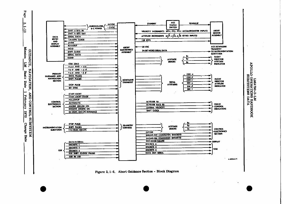
2.1.1.2 Abort Guidance Section. (See figure 2.1-6.)
The AGS consists of an abort sensor assembly (ASA), abort electronics assembly (AEA), and a data entry and display assembly (DEDA). The ASA performs the same function as the IMU; it
I establishes an inertial reference frame. The AEA, a high-speed, general-purpose digital computer, is the central processing and computational device for the AGS. The DEDA is the input-output device for controlling the AEA.
Navigation is performed by the AGS through integration of the equations of motion and substitution of instantaneous LM velocity for the variables. The AGS decodes the PGNS downlink data to establish LM and CSM position, velocity, and associated time computations. This infOrmation is used to initialize or update the AGS navigational computations upon command from the DEDA. The AGS solves the guidance problems of five distinct guidance routines: orbit insertion, coelliptic sequence
■ initiate, constant delta (a) altitude, terminal phase initiate, and change in LM velocity (external AV).
GUIDANCE, NAVIGATION, AND CONTROL SUBSYSTEM Page 2.1-8 Mission LM Basic Date 1 February 1970 Change Date 15 June 1970
S
•
LMA790-3-LM
APOLLO OPERATIONS HANDBOOK SUBSYSTEMS DATA
TEMPERATURE PROGRAM COMPUTER ACTIVITY GIMBAL LOCK CAUTION LIGHT CONDITION LIGHT STATUS LIGHT VERB CODE PROGRAM NUMBER
(YELLOW) (Yellow) (YELLOW) (GREEN) DISPLAY DISPLAY
Nevem AB peshbettee twitches. Mclean nvmsH keys (0 the 9) and + and —keys. an ssesnentary poehbewens.
-92 911 +13E1 0 - '16514
NOUN Vat PUSHBUTTON PUSHBUTTON
UPLINK ACTMTY STATUS LIGHT (WHITE)
NO ATTITUDE STATUS LIGHT (WHITE)
STANDBY STATUS UGHT (WH
KEY RELEASE STATUS LIGHT (WHITE)
OPERATOR ERROR STATUS LIGHT (WHITE)
RESTART CONDITION LIGHT (YELL
TRACKER CONDITION LIGHT (YELLOW
LR ALTITDE DATA NO GOOD CAUTION
LIGHT (YELLOW)
LB VELOCITY DATA NO GOOD CAUTION
LIGHT (YELLOW)
NOUN CODE DISPLAY
DATA DISPLAY ,(REGISTER 1)
DATA DISPLAY (REGISTER 2)
DATA DISPLAY (REGISTER 9)
CLEAR DATA PUSHBUTTON
ENTER DATA PUSHBUTTON
PROCEED PUSHBUTTON
RESET PUSHBUTTON
KEY RELEASE PUSHBUTTON
SONLMS•IS
Figure 2.1 7 5. Display and Keyboard Assembly
The AGS provides steering commands for three steering submodes: attitude hold, guidance steering, and acquisition steering. The attitude hold submode maintains the vehicle attitude that exists when the submode is entered. In the guidance steering submode, the AEA generates attitude commands ■ to orient the LM X-axis so that it lies along the direction of the thrust vector. In the acquisition steering submode, the AEA generates attitude commands to orient the LM Z-axis along the estimated line of sight ■ (LOS) between the LM and CSM.
The AGS outputs an engine-on or engine-off command during all thrusting maneuvers. If the PGNS is in control, the command is a blowup of the signal produced by the PGNS. If the AGS is in control,' the engine-on command can be routed only after the appropriate switches are set and the ullage maneuver has been performed. When proper velocity-to-be-gained are achieved, an engine-off command is issued.
The AGS uses RR angle information and accepts range and range-rate information from the RR for updating LM navigation so that the LM Z-axis is toward the CSM, or for midcourse correction. These data are manually inserted into the AEA by the astronaut by using the DEDA.
The AGS automatically aligns the strapped-down inertial system of the ASA by computing the direction cosines that relate the LM body axes to the desired inertial coordinate system. It also provides in-flight gyro and accelerometer calibration to compensate for fixed non-g gyro drift, and telemetry data for MSFN through the IS.
2. 1. 1. 2. 1 Abort Sensor Assembly.
The ASA, by means of gyros and accelerometers, provides incremental attitude information around the vehicle X, Y, and Z axes and incremental velocity changes along the vehicle X, Y, and Z axes. Data pulses are routed to the AEA, which uses the attitude and velocity data for computation of steering errors. The ASA is mounted on the navigation base above the astronauts' heads, between the crew com-partment and the thermal and micrometeoroid shield.
GUIDANCE, NAVIGATION, AND CONTROL SUBSYSTEM Mission LM Basic Date 1 February 1970 Change Date 15 June 1970 Page 2.1-9
CD
ts3
0
0
z
O
8
0L6T
Axe
ructe
a I
+4 VDC STANDBY
DATA ENTRY AND
DISPLAY ASSEMBLY
AGS STATUS SWITCH
ELECTRONICS ASSEMBLY
DOWNLINK TELEMETRY
WARMUP UNREGULATED
{
D-C POWER —2 VDC
VELOCITY INCREMENTS (Oh, (ACCELEROMETER INPUTS) SHIFT 4 BITS IN AVy, Ohl SHIFT 4 BITS OUT
SERIAL DATA ATTITUDE INCREMENTS 16 P, d f0, d fIl (GYRO INPUTS/
128-KPPS CLOCK 12B KPPS ENTER
2$ VDC
24-BIT WORDSERIAL DATA
READOUT
0.
ABORT SENSOR
ASSEMBLY
AGS DOWNLINK TELEMETRY TO INSTRUMENTATION SUBSYSTEM
FLIGHT DIRECTOR ATTITUDE INDICATOR
RIGHT DIRECTOR ATTITUDE INDICATOR
FLIGHT CONTROL INDICATORS
CONTROL ELECTRONICS SECTION
DISPLAY
HOLD
SHIFT CLOCK
SERIAL DATA
ATTITUDE
{
ET
ERRORS
TOTAL ATTITUDES
CLEAR
• ,
GUIDANCE
INSTRUMENTATION
PRIMARY AND
NAVIGATION SECTION
CONTROL ELECTRONICS
SECTION
SUBSYSTEM
GSE
CDU ZERO
+d8 AND — 11%
COS a 15.
+4 * AND — d IS
+d # AND -a # DATA PULSES go. SHIFT PULSES COS P
111.
STOP PULSE
COS Y
SIN a
BIT SYNC SN P
START ABORT
SIN V
ALTITUDE MI •••
START ABORT STAGE
FOLLOWUP
AUTOMATIC
ASCENT ENGINE ON ALTITUDE RATE (K)
DESCENT ENGINE ON LATERAL VELOCITY •
211-VRMS, 800-CPS REFERENCE SHIFT CLOCK
STOP PULSE
ATTITUDE ERRORS
111.
SHIFT PULSES TELEMETRY CONTROL S
115-VIIMS, 400 CPS
DATA IN SERIAL
CUTOFF ENGINE-OFF COMMANDS (DISCRETE)
11. ENGINE-ON COMMANDS (DISCRETE
,110 TEST MODE FAIWRE •
DISCRETE 1 DISCRETE 4 110. DISCRETE 2 DISCRETE S
DISCRETE 3 DISCRETE 6 GSE SHIFT ICLOCIO PULSES DATA OUT SERIAL
GSE IN USE
• A•3001At471
Figure 2. 1-6. Abort Guidance Section - Block Diagram
• • •
LMA790-3-LM APOLLO OPERATIONS HANDBOOK
SUBSYSTEMS DATA
The ASA consists of three strapped-down pendulous accelerometers, three strapped-down gyros, and associated electronic circuitry. The accelerometers and gyros (one each for each vehicle axis) sense body-axis motion with respect to inertial space. The accelerometers sense acceleration along the vehicle orthogonal axis. The gyros and accelerometers are securely fastened to the vehicle X, Y, and Z axes so that motion along or around one or more axis is sensed by one or more gyros or accelerometers.
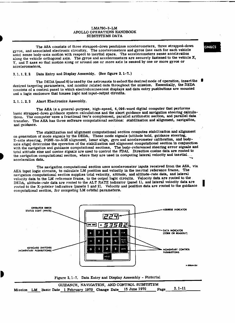
2.1.1.2.2 Data Entry and Display Assembly. (See figure 2.1-'1.)
The DEDA (panel 6) is used by the astronauts to select the desired mode of operation, insert the I desired targeting parameters, and monitor related data throughout the mission. Essentially, the DEDA consists of a control panel to which electroluminescent displays and data entry pushbuttons are mounted and a logic enclosure that houses logic and input-output circuits.
2.1.1.2.3 Abort Electronics Assembly.
The AEA is a general-purpose, high-speed, 4,096-word digital computer that performs basic strapped-down guidance system calculations and the abort guidance and navigation steering calcula-tions. The computer uses a fractional two's complement, parallel arithmetic section, and parallel data transfer. The AEA has three software computational sections: stabilization and alignment, navigation, and guidance.
The stabilization and alignment computational section computes stabilization and alignment on generation of mode signals by the DEDA. These mode signals (attitude hold, guidance steering, Z-axis steering, PGNS-to-AGS alignment, lunar align, gyro and accelerometer calibration, and body-axis align) determine the operation of the stabilization and alignment computational section in conjunction with the navigation and guidance computational sections. The body-referenced steering error signals and total attitude sine and cosine signals are used to control the FDAI. Direction cosine data are routed• to the navigation computational section, where they are used in computing lateral velocity and inertial acceleration data.
The navigation computational section uses accelerometer inputs received from the ASA, via AEA input logic circuits, to calculate LM position and velocity in the inertial reference frame. The navigation computational section supplies total velocity, altitude, and altitude-rate data, and lateral velocity data in the LM reference frame, to the output logic circuits. Velocity data are routed to the DEDA, altitude-rate data are routed to the ALT RATE indicator (panel 1), and lateral velocity data are routed to the X-pointer indicators (panels 1 and 2). Velocity and position data are routed to the guidance computational section, for computing LM orbital parameters.
1E2'1 1+535E72
an
DUO
(MOMENTARY PUSHBUTTONS) KEYBOARD SWITCHES nun0
[HOLD
ADDRESS INDICATOR
OM !RR
9
READ OUT
ENTR
DATA INDICATOR (CODE OR READOUT)
MOMENTARY CONTROL PUSHBUTTONS
A•3001A14254
OPERATOR ERROR STATUS LIGHT (WHITE)
Figure 2.1-7. Data Entry and Display Assembly - Pictorial
GUIDANCE, NAVIGATION, AND CONTROL SUBSYSTEM Mission LM Basic Date 1 February 1970 Change Date 15 June 1970 Page 2.1-11

LMA790-3-LM APOLLO OPERATIONS HANDBOOK
SUBSYSTEMS DATA
The guidance computational section provides trajectory computation and selection, steering computation, and midcourse-correction computation. This computational section receives data relating to the CSM state vector and the LM state vector from the LGC in other external source through the AGS input
■ selector logic. The state vector is the vehicles attitude and velocity for a given mission time. Body referenced steering errors are received from the stabilization and alignment computational section, for trajectory computation. The LM abort guidance problem consists of solving the equations of the selected guidance maneuver, including steering, attitude, and engine control computations. Outputs of the guidance computational section, through the output select logic circuits, include engine on and off signals to the CES, and velocity to be gained (selectable by DEDA readout).
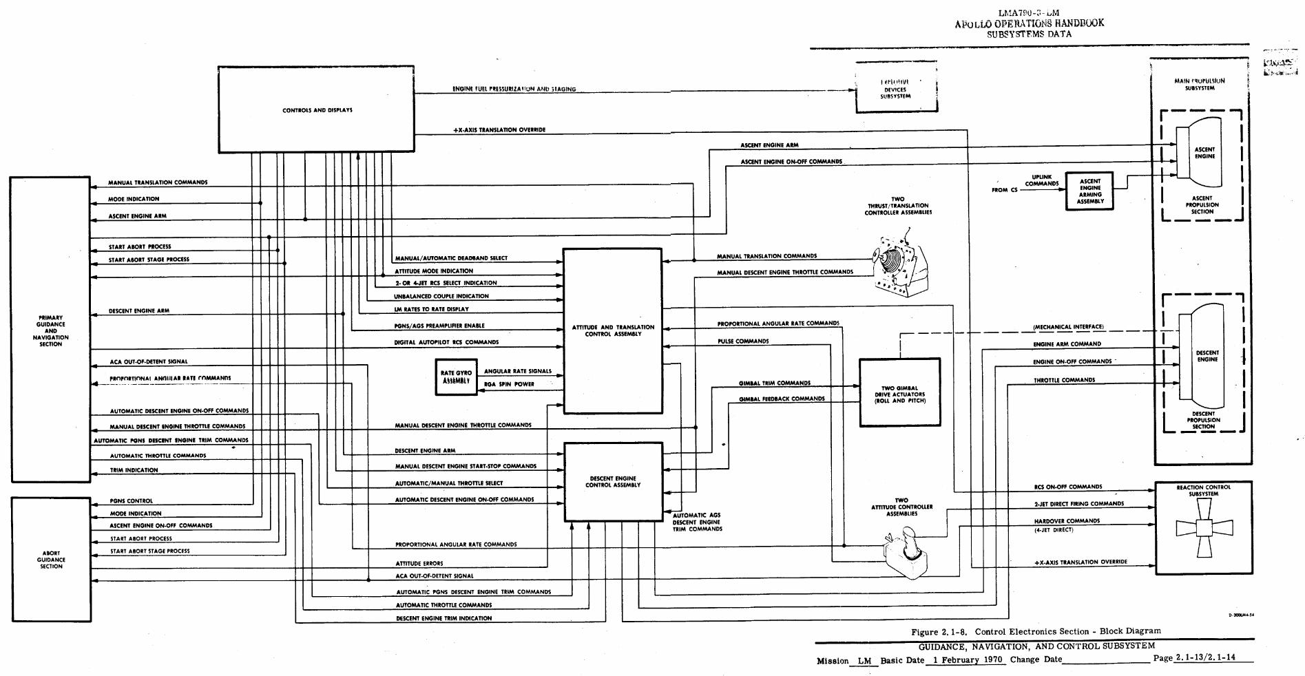
2. 1. 1. 3 Control Electronics Section. (See figure 2. 1-8.)
The CES processes attitude and translation signals when operating in the primary guidance mode or the abort guidance mode.
When operating in the primary mode, the CES converts RCS commands to the required electrical power to operate the RCS solenoid valves. The CES accepts discrete (on and off) descent engine gimbal commands and, upon receipt of an on command, causes the descent engine to move about its gimbal axis. The CES accepts LGC and manual engine on and off commands and routes them to the MPS to fire or stop the descent or ascent engine. The CES accepts LGC and manual thrust commands to throttle the descent engine (10% to 92. 5% of maximum thrust). The CES also provides manual attitude and translation commands to the LGC.
When operating in the abort guidance mode, the CES accepts attitude error signals from the AGS, or manual attitude rate commands from the attitude hand controller or rate-damping signals from a gyro assembly, and fires the RCS thrusters to achieve attitude control. The CES accepts manual transla-tion commands and fires the appropriate thrusters to accelerate the LM in the desired direction. The CES automatically gimbals the descent engine for trim control in accordance with signal polarity. The CES accepts AGS and manual engine on and off commands and routes them to the descent or ascent engine. The CES accepts manual throttle commands to control descent engine thrust and accepts manual rota-
■ tional, low-amplitude acceleration, open-loop commands.
The CES comprises two attitude controller assemblies (ACA's), two thrust/translation con-troller assemblies (TTCA's), an attitude and translation control assembly (ATCA), a rate gyro'assembly
■ (RGA), descent engine control assembly (DECA), two gimbal drive actuators (GDA's), an ascent engine arming assembly (ARAM, and three stabilization and control (S&C) control assemblies.
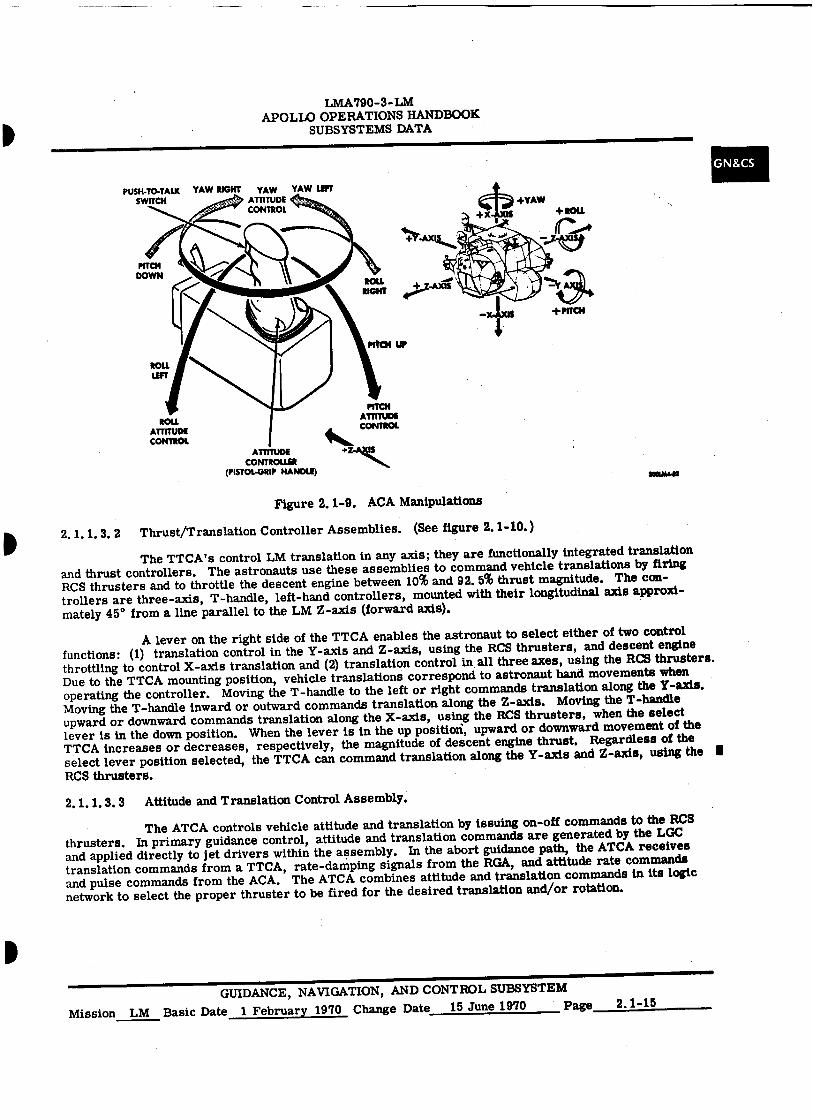
2.1.1.3.1 Attitude Controller Assemblies. (See figure 2.1-9.)
The ACA's are right-hand pistol grip controllers, which the astronauts use to command changes in vehicle attitude. Each ACA is installed with its longitudinal axis approximately parallel to the X-axis. Each ACA supplies attitude rate commands proportional to the displacement of its handle, to the LGC and the ATCA; an out-of-detent discrete each time the handle is out of its neutral position; and a followup discrete to the AGS each time the controller is out of detent. A trigger-type push-to-talk switch on the pistol grip handle of the ACA is used for communication with the CSM and ground facilities.
As the astronaut uses his ACA, his hand movements are analogous to vehicle rotations. Clockwise or counterclockwise rotation of the controller commands yaw right or yaw left, respectively. Forward or aft movement of the controller commands vehicle pitch down or up, respectively. Left or right movement of the controller commands roll left or right, respectively.
The ACA's are also used in an incremental landing point designator (LPD) mode, which is available to the astronauts during the final approach phase. In this mode, the angular error between the designated landing site and the desired landing site is nulled by repetitive manipulation of an ACA. LPD signals from the ACA are directed to the LGC, which issues commands to move the designated landing site incrementally along the Y-axis and Z-axis.
GUIDANCE, NAVIGATION, AND CONTROL SUBSYSTEM Page 2.1-12 Mission LM Basic Date 1 February 1970 Change Date 15 June 1970
•
•
•
MANUAL TRANSLATION COMMANDS
MODE INDICATION
ASCENT ENGINE ARM
MANUAL DESCENT ENGINE START-STOP COMMANDS
PULSE COMMANDS
AUTOMATIC/MANUAL THROTTLE SELECT
LtiA7Pu4-i,m APULW OPERATIONS HANDBOOK
SUBSYSTEMS DATA
■011,•••■■IMPI
ASCENT ENGINE ARM
CONTROLS AND DISPLAYS
ENGINE FUEL PRESSURIZA MIN ATTU STAGING
+X-AXIS TRANSLATION OVERRIDE
MAIN flUIIIISIUN SUBSYSTEM
r-
I.
I T PI IIkIVT DEVICES
SUBSYSTEM
ASCENT ENGINE
r.
ASCENT ENGINE ON-OFF COMMANDS
PRIMARY GUIDANCE
AND NAVIGATION
SECTION
Rd moo ASCENT
PROPULSION - SECTION
■
I
START ABORT PROCESS
START ABORT STAGE PROCESS
ATTITUDE MODE INDICATION
ACA OUT-OF-DETENT SIGNAL 1111 II 1111 II
N
PGNS/AGS PREAMPLIFIER ENABLE DIGITAL AUTOPILOT RCS COMMANDS
Lm2- OR T4:SIETTO RRCASTESEDLIESCTPLAIYNDICATION
UNBALANCED COUPLE INDICATION
DESCENT ENGINE ARM
111141111 11111 COMMANDS
■
MANUAL/AUTOMATIC DEADRAND SELECT
PROPnRTInNA I AMIE AP RATE rnmomoins
AUTOMATIC DESCENT ENGINE ON-OFF COMMANDS
RATE GYRO
MONK V ANGULAR RATE SIGNALS
RGA SPIN POWER
MANUAL DESCENT ENGINE THROTTLE COMMANDS MANUAL DESCENT ENGINE THROTTLE COMMANDS
AUTOMATIC PONS DESCENT ENGINE TRIM
AUTOMATIC THROTTLE COMMANDS DESCENT ENGINE ARM
TRIM INDICATION
ATTITUDE AND TRANSLATION CONTROL ASSEMBLY
GIMBAL TRIM COMMANDS
GIMBAL FEEDBACK COMMANDS 111 I L
I
I
DESCENT
SECTION OWN=
PROPULSION
TWO THRUST/TRANSLATION
CONTROLLER ASSEMBLIES
■MIN1111
DESCENT ENGINE CONTROL ASSEMBLY
MANUAL TRANSLATION COMMANDS
MANUAL DESCENT ENGINE THROTTLE COMMANDS
RCS ON-OFF COMMANDS REACTION CONTROL SUBSYSTEM AUTOMATIC DESCENT ENGINE ON-OFF COMMANDS PGNS CONTROL
MODE INDICATION 2-JET DIRECT FIRING COMMANDS
NARDOVER COMMANDS ASCENT ENGINE ON-OFF COMMANDS AUTOMATIC AGS DESCENT ENGINE TRIM COMMANDS
START ABORT PROCESS PROPORTIONAL ANGULAR RATE COMMANDS
IIIR START ABORT STAGE PROCESS
(4-JET DIRECT)
+X-AXIS TRANSLATION OVERRIDE ATTITUDE ERRORS
ABORT GUIDANCE
SECTION
ACA OUT-OF-DETENT SIGNAL
AUTOMATIC PGNS DESCENT ENGINE TRIM COMMANDS
AUTOMATIC THROTTLE. COMMANDS
DESCENT ENGINE TRIM INDICATION D. 300UA4.5/
Figure 2.1-8. Control Electronics Section - Block Diagram
GUIDANCE, NAVIGATION, AND CONTROL SUBSYSTEM
Mission LM Basic Date 1 February 1970 Change Date Page 2.1-13/2.1-14
PUSH-TO-TALK YAW RIGHT YAW YAW LEFT SWITCH ATTITUDE
CONTROL
ROLL ATTITUDE CONTROL 41111111‘.
PITCH ATTITUDE CONTROL
LMA790-3-LM APOLLO OPERATIONS HANDBOOK
SUBSYSTEMS DATA
ATTITUDE CONTROLLER
(PISTOL-GRIP HANDLE)
GN&CS
Figure 2.1-9. ACA Manipulations
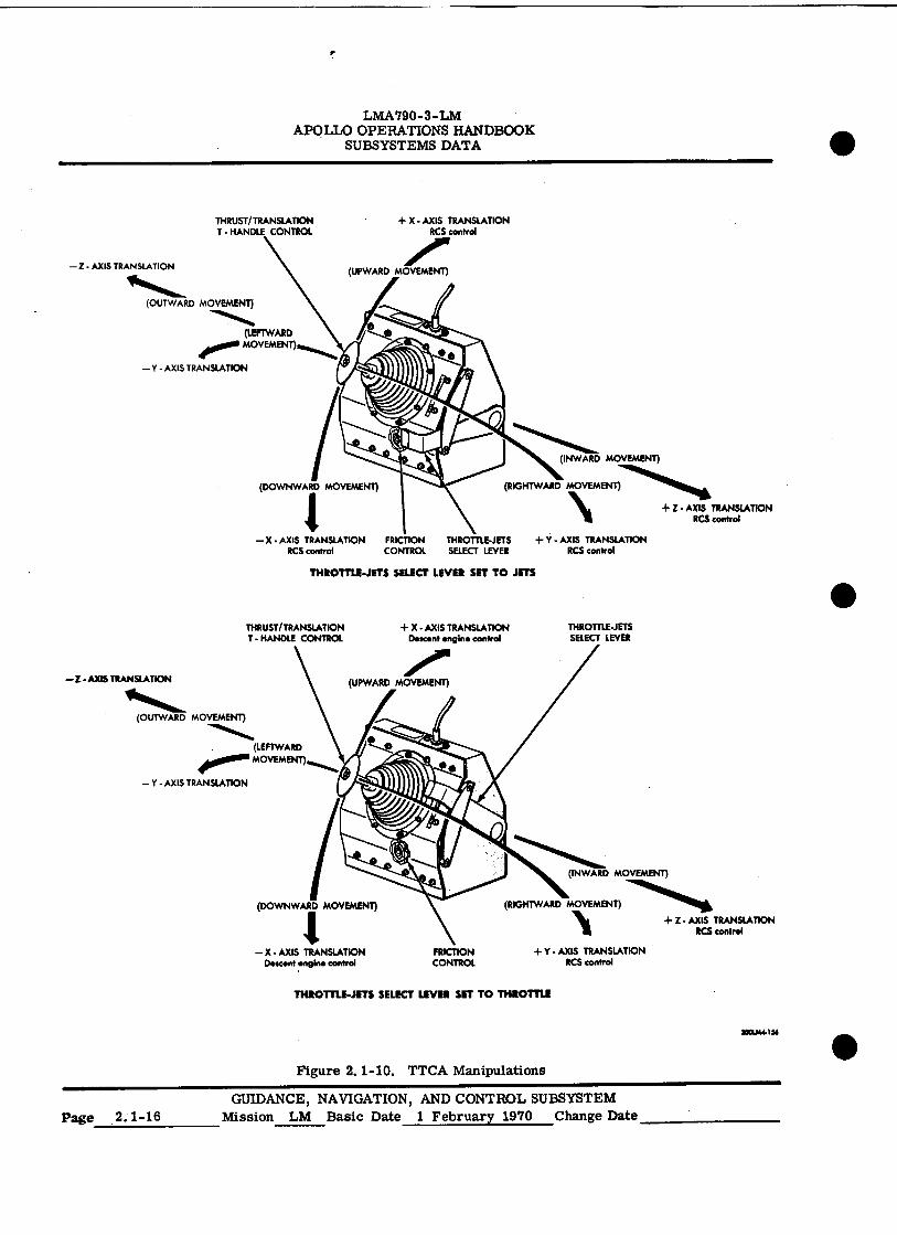
2.1.1.3.2 Thrust/Translation Controller Assemblies. (See figure 2.1-10.)
The TTCA's control LM translation in any axis; they are functionally integrated translation and thrust controllers. The astronauts use these assemblies to command vehicle translations by firing RCS thrusters and to throttle the descent engine between 10% and 92.5% thrust magnitude. The con-trollers are three-axis, T-handle, left-hand controllers, mounted with their longitudinal axis approxi-mately 45° from a line parallel to the LM Z-axis (forward axis).
A lever on the right side of the TTCA enables the astronaut to select either of two control functions: (1) translation control in the Y-axis and Z-axis, using the RCS thrusters, and descent engine throttling to control X-axis translation and (2) translation control in all three axes, using the RCS thrusters. Due to the TTCA mounting position, vehicle translations correspond to astronaut hand movements when operating the controller. Moving the T-handle to the left or right commands translation along the Y-axis. Moving the T-handle inward or outward commands translation along the Z-axis. Moving the T-handle upward or downward commands translation along the X-axls, using the RCS thrusters, when the select lever is in the down position. When the lever is in the up position, upward or downward movement of the TTCA increases or decreases, respectively, the magnitude of descent engine thrust. Regardless of the select lever position selected, the TTCA can command translation along the Y-axis and Z-axis, using the ■ RCS thrusters.
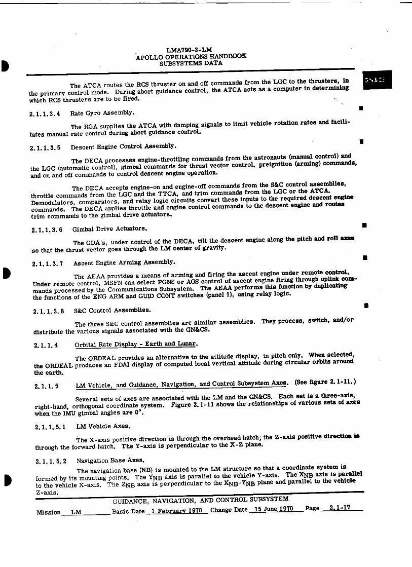
2.1.1.3.3 Attitude and Translation Control Assembly.
The ATCA controls vehicle attitude and translation by issuing on-off commands to the RCS thrusters. In primary guidance control, attitude and translation commands are generated by the LGC and applied directly to jet drivers within the assembly. In the abort guidance path, the ATCA receives translation commands from a TTCA, rate-damping signals from the RGA, and attitude rate commands and pulse commands from the ACA. The ATCA combines attitude and translation commands in its logic network to select the proper thruster to be fired for the desired translation and/or rotation.
GUIDANCE, NAVIGATION, AND CONTROL SUBSYSTEM Mission LM Basic Date 1 February 1970 Change Date 15 June 1970 Page 2.1-15
THRUST/TRANSLATION
+ X - AXIS TRANSLATION T HANDLE CONTROL
RCS control
— Z - AXIS TRANSLATION
1011111%.41._
(OUTWARD MOVEMENT)
(LEFTWARD 000 MOVEMENT)
Y - AXIS TRANSLATION
Z • AXIS TRANSLATION RCS control
THRUST/TRANSLATION T HANDLE CONTROL
THROTTLE-JETS SELECT LEVER
Y AXIS TRANSLATION RCS control
FRICTION CONTROL
—Z- AXIS TRANSLATION
(OUTWARD MOVEMENT)
(LEFTWARD 400.10. MOVEMENT)
— Y - AXIS TRANSLATION
(RIGHTWARD MOVEMENT)
Z - AXIS TRANSLATION RCS control
LMA790-3-LM APOLLO OPERATIONS HANDBOOK
SUBSYSTEMS DATA
THROTTLE-JETS SELECT LEVER SET TO JETS
THROTTLE-JETS SELECT LEVER SIT TO THROTTLE
3001.1144134
Figure 2.1-10. TTCA Manipulations
GUIDANCE, NAVIGATION, AND CONTROL SUBSYSTEM Page 2.1-16
Mission LM Basic Date 1 February 1970 Change Date
•
LMA790-3-LM APOLLO OPERATIONS HANDBOOK
SUBSYSTEMS DATA
The ATCA routes the RCS thruster on and off commands from the LGC to the thrusters, in the primary control mode. During abort guidance control, the ATCA acts as a computer in determining which RCS thrusters are to be fired.
2.1.1.3.4 Rate Gyro Assembly.
The RGA supplies the ATCA with damping signals to limit vehicle rotation rates and facili-tates manual rate control during abort guidance control.
2.1.1.3.5 Descent Engine Control Assembly.
The DECA processes engine-throttling commands from the astronauts (manual control) and the LGC (automatic control), gimbal commands for thrust vector control, preignition (arming) commands, and on and off commands to control descent engine operation.
The DECA accepts engine-on and engine-off commands from the S&C control assemblies, throttle commands from the LGC and the TTCA, and trim commands from the LGC or the ATCA. Demodulators, comparators, and relay logic circuits convert these inputs to the required descent engine commands. The DECA applies throttle and engine control commands to the descent engine and routes trim commands to the gimbal drive actuators.
2.1.1.3.6 Gimbal Drive Actuators.
The GDA's, under control of the DECA, tilt the descent engine along the pitch and roll axes so that the thrust vector goes through the LM center of gravity.
2.1.1.3.7 Ascent Engine Arming Assembly.
The AEAA provides a means of arming and firing the ascent engine under remote control. Under remote control, MSFN can select PGNS or AGS control of ascent engine firing through uplink com-mands processed by the Communications Subsystem. The AEAA performs this function by duplicating the functions of the ENG ARM and GUM CONT switches (panel 1), using relay logic.
2.1.1.3. 8 381C Control Assemblies.
The three S&C control assemblies are similar assemblies. They process, switch, and/or distribute the various signals associated with the GN&CS.
2.1.1.4 Orbital Rate Display - Earth and Lunar.
The ORDEAL provides an alternative to the attitude display, in pitch only. When selected, the ORDEAL produces an FDAI display of computed local vertical attitude during circular orbits around the earth.
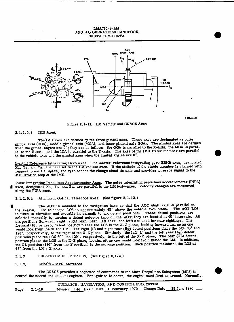
2.1.1.5 LM Vehicle, and Guidance, Navigation, and Control Subsystem Axes. (See figure 2.1-11.)
Several sets of axes are associated with the LM and the GN&CS. Each set is a three-axis, right-hand, orthogonal coordinate system. Figure 2.1-11 shows the relationships of various sets of axes when the IMU gimbal angles are 0 ° .
2.1.1.5.1 LM Vehicle Axes.
The X-axis positive direction is through the overhead hatch; the Z-axis positive direction is through the forward hatch. The Y-axis is perpendicular to the X-Z plane.
2.1.1.5.2 Navigation Base Axes.
The navigation base (NB) is mounted to the LM structure so that a coordinate system is formed by its mounting points. The YNB axis is parallel to the vehicle Y-axis. The XNB axis is parallel to the vehicle X-axis. The ZNB axis is perpendicular to the XNB-YNB plane and parallel to the vehicle Z-axis.
GUIDANCE, NAVIGATION, AND CONTROL SUBSYSTEM
Mission LM Basic Date 1 February 1970 Change Date 15 June 1970 Page 2.1-17
AOT OGA SHAFT AXIS
X 4 ▪ 4
•
• PTA AOT LOS
LM +Z-AXIS
0-+
11-31101MI-140
LMA790-3-LM APOLLO OPERATIONS HANDBOOK
SUBSYSTEMS DATA
Figure 2.1-11. LM Vehicle and GN&CS Axes
2.1.1.5.3 IMU Axes.
The IMU axes are defined by the three gimbal axes. These axes are designated as outer gimbal axis (OGA), middle gimbal axis (MGA), and inner gimbal axis (IGA). The gimbal axes are defined when the gimbal angles are 0 ° ; they are as follows: the OGA is parallel to the X-axis, the MGA is paral-lel to the Z-axis, and the IGA is parallel to the Y-axis. The axes of the IMU stable member are parallel to the vehicle axes and the gimbal axes when the gimbal angles are 0 ° .
Inertial Reference Integrating Gyro Axes. The inertial reference integrating gyro (TRIG) axes, designated Xg, Yg, and Zg, are parallel to the LM vehicle axes. If the attitude of the stable member is changed with respect to inertial space, the gyro senses the change about its axis and provides an error signal to the stabilization loop of the IMU.
Pulse Integrating Pendulous Accelerometer Axes. The pulse integrating pendulous accelerometer (PIPA) I axes, designated Xa, Ya, and Za, are parallel to the LM body-axes. Velocity changes are measured
along the PIPA axes.
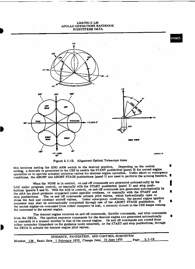
2.1.1.5.4 Alignment Optical Telescope Axes. (See figure 2.1-12.)
The AOT is mounted to the navigation base so that the AOT shaft axis is parallel to the X-axis. The telescope LOS is approximately 45 ° above the vehicle Y-Z plane. The AOT LOS is fixed in elevation and movable in azimuth to six detent positions. These detent positions are selected manually by turning a detent selector knob on the AOT; they are located at 80 ° intervals. All six positions (forward, right, right rear, rear, left rear, and left) are used for star sightings. The forward (F), or zero, detent position places the LOS in the X-Z plane, looking forward and up as one would look from inside the LM. The right (R) and right rear (RR) detent positions place the LOS 60 ° and 120° , respectively, to the right of the X-Z plane. Similarly, the left (L) and the left rear (LR) detent positions place the LOS 60° and 120°, respectively, to the left of the X-Z plane. The rear (CL) detent position places the LOS in the X-Z plane, looking aft as one would look from inside the LM. In addition, the CL position (180 ° from the F position) is the stowage position. Each position maintains the LOS at 45° from the LM + X-axis.
2.1.2 SUBSYSTEM INTERFACES. (See figure 2.1-2.)
2.1.2.1 GN&CS - MPS Interfaces.
The GN&CS provides a sequence of commands to the Main Propulsion Subsystem (MPS) to control the ascent and descent engines. For ignition to occur, the engine must first be armed. Normally,
GUIDANCE, NAVIGATION, AND CONTROL SUBSYSTEM Page 2.1-18 Mission LM Basic Date 1 February 1970 Change Date 15 June 1970
•
•
•
-`,
+Y
+3
+Z-AXIS 0'
300' 240'
270'
I
+X
• •
120' or +1' - AXIS
or
180"
L4OCIM1- 143
+X
SIM VIM
LMA790-3-LM APOLLO OPERATIONS HANDBOOK
SUBSYSTEMS DATA
GN&CS
Figure 2.1-12. Alignment Optical Telescope Axes
this involves setting the ENG ARM switch to the desired position. Depending on the switch ■ setting, a discrete is generated in the CES to enable the START pushbutton (panel 5) for ascent engine operation or to operate actuator isolation valves for descent engine operation. Under abort or emergency conditions, the ABORT and ABORT STAGE pushbuttons (panel 1) are used to perform the arming function. ■
When the PGNS is in control, on and off commands are generated automatically by the LGC under program control, or manually with the START pushbutton (panel 5) and stop push-buttons (panels 5 and 6). With the AGS in control, on and off commands are generated automatically by the AEA (an abort guidance computer) under specific routines, or manually with the START and ■ stop pushbuttons. The on and off commands actuate pilot valves, which hydraulically open or close the fuel and oxidizer shutoff valves. Under emergency conditions, the ascent engine ignition sequence may also be automatically completed through use of the ABORT STAGE pushbutton. If ■ the ascent engine-on command from either computer is lost, a memory circuit in the CES keeps issuing the command to the ascent engine.
The descent engine receives on and off commands, throttle commands, and trim commands from the DECA. The ignition sequence commands for the descent engine are generated automatically ■ or manually in a manner similar to that of the ascent engine. On and off commands are routed from either computer (dependent on the guidance mode selected), or the START and stop pushbuttons, through the DECA to actuate the descent engine pilot valves.
GUIDANCE, NAVIGATION, AND CONTROL SUBSYSTEM Mission LM Basic Date 1 February 1970 Change Date 15 June 1970 Page 2.1-19
LM.A790-3-LM APOLLO OPERATIONS HANDBOOK
SUBSYSTEMS DATA
Throttle commands to the descent engine are generated automatically by the LGC under ■ program control, or manually with a TTCA. The TTCA can be used to override LGC throttle commands.
The AGS cannot throttle the descent engine. Throttle commands cause the throttle actuator of the descent engine to change the position of the flow control valves and vary the injector orifice of the engine. Changing the position of the flow control valves changes the quantity of fuel and oxidizer metered into the engine and thus changes the magnitude of engine thrust.
The GN&CS generates trim commands to tilt the descent engine to control the direction of the thrust vector. The descent engine is tilted about the LM Y-axis and Z-axis to compensate for the offset of the center of gravity due to fuel depletion during descent engine operation. The thrust vector is
■ controlled by the LGC with the aid of two GDA's. The GDA's are pinned to the descent engine and the LM structure along the Y-axis (roll) and Z-axis (pitch). When actuated, the GDA's extend or retract a screwjack-actuated arm that tilts the engine to attain the desired thrust vector. Thrust vector control for the ascent engine is achieved through firing of selected upward-firing TCA's.
2. 1. 2. 2 GN&CS - RCS Interface.
The GN&CS provides on and off commands to the 16 TCA's (referred to as thrusters or jets) to control LM attitude and translation. In the primary mode of operation (PGNS in control), the LGC generates the required commands and sends them to the proper jet drivers in the CES. The jet drivers send selected on and off commands to the RCS primary solenoids. In the secondary mode of operation
■ (AGS in control), the AGS supplies the CES with attitude errors. The ATCA in the CES uses these inputs to select the proper thruster for attitude and translation control.
■ The thrusters are controlled manually with an ACA and a TTCA. The ACA pro-vides attitude commands and the TTCA provides translation commands to the LGC during the primary mode of operation and to the ATCA during the secondary mode of operation. The ACA can fire the thrusters directly during the pulse, direct, and hardover modes, bypassing the LGC or AEA,
■ and the ATCA. The four downward-firing thrusters may be fired by pressing the +X TRANSL pushbutton (panel 5). The on and off commands supplied to the thruster take the form of a step function. The dura-tion of the signal determines the firing time of the selected thruster, which ranges from a pulse (less than 1 second) to steady-state (1 second or longer).
Each thruster contains an oxidizer solenoid valve and a fuel solenoid valve which, when open, pass propellant through an injector into the combustion chamber, where ignition occurs. Each valve contains a primary (automatic) solenoid and a secondary (direct) solenoid, which open the valve when energized. On and off commands from the ATCA are applied to the primary solenoids; the direct commands are applied to the secondary solenoids.
2.1.2.3 GN&CS - EPS Interface.
The Electrical Power Subsystem (EPS) supplies primary d-c and a-c power to the GN'&CS. This power originates from six silver-zinc batteries (four in the descent stage and two in the ascent
■ stage). An additional battery has been added in the ascent stage for LM 10 and subsequent. The descent batteries feed power to the buses during all operations, before staging. Immediately before staging occurs, ascent battery power is switched on and descent battery power is terminated. A deadface relay circuit deadfaces the descent batteries when normal staging occurs. Under emergency conditions, when the ABORT STAGE pushbutton is pressed, a power switchover command, which initiates deadfacing automatically, is routed to the EPS. The 28-volt d-c battery power is routed through an inverter to pro-vide 115-volt, 400-cps ac to the GN&CS equipment. Refer to paragraph 2.1.3.6 for a functional descrip-tion of power distribution.
2. 1. 2. 4 GN&CS - ECS Interface.
The Environmental Control Subsystem (ECS) provides thermal stability for the temperature-' sensitive electronic equipment of the GN&CS. The electronic equipment (except the IMU) is mounted on 1 cold plates and rails through which ECS coolant (ethylene glycol-water solution) is routed to remove heat.
To cool the IMU, the coolant flows through its case. The heat that is removed from the equipment is vented overboard by the ECS sublimators.
...1■■11■11.1 .m.•■•■■■•■••••■•■• •■
Page 2.1-20 GUIDANCE, NAVIGATION, AND CONTROL SUBSYSTEM
Mission LM Basic Date 1 February 1970 Change Date 15 June 1970
•
•
•
•
LMA790-3-LM APOLLO OPERATIONS HANDBOOK
SUBSYSTEMS DATA
2. 1. 2. 5 GN&CS - CS Interface.
GN&CS
The Communications Subsystem (CS) interfaces directly with the GN&CS when the astronaut uses a push-to-talk switch on his ACA. When the switch is pressed, the ACA issues a d-c signal that enables an audio center in the signal-processor assembly of the VHF/AM communications. This enabling signal allows the audio signals from the microphones to be processed by the CS. Automatic re-mote control of the LGC is provided through use of a digital uplink assembly (DUA). Uplink commands from MSFN, processed by the DUA, are used for program control. The CS interfaces indirectly with the GN&CS, using VHF/AM communications for voice uplink commands. It also interfaces with a tone generator in the CES. The generator, enabled by a command from the master alarm circuit of the Instrumentation Subsystem (IS), issues a 1-kc tone to the astronaut headsets as an indication of a sub-system malfunction.
2. 1. 2. 6 GN&CS - EDS Interface.
The GN&CS interfaces with the Explosive Devices Subsystem (EDS) by supplying a descent engine on signal to the supercritical helium explosive valve and an ascent engine on signal, which initiates the staging sequence. When the descent engine is operated for the first time, the MASTER ARM switch (panel 8) is set to ON so that the supercritical helium explosive valve is blown when the descent engine on ■ signal is issued. All other normal pressurization and staging sequences are initiated by the astronauts.
During an emergency situation, the ABORT STAGE pushbutton when pushed, shuts down the descent engine and pressurizes the APS, blowing the helium tank explosive valves that are selected by the ASC He SEL switch (panel 8). After a time delay, the GN&CS generates an ascent engine on signal which initiates the staging sequence as the ascent engine begins to fire. Upon completion of staging, a stage status signal is routed from the EDS deadface switch to the ATCA and to the LGC. This signal automati-cally selects the power deadband for RCS control during ascent engine operation.
2. 1. 2. 7 GN&CS - IS Interface.
The Instrumentation Subsystem (IS) senses GN&CS physical status data, monitors the GN&CS equipment, and performs in-flight checkout. The data signals are conditioned by the signal-conditioning electronics assembly (SCEA) and supplied to the pulse-code-modulation and timing electronics assembly (PCMTEA) and the caution and warning electronics assembly (CWEA). The PCMTEA changes the input signals to a serial digital form for transmission to MSFN. The CWEA checks the status of the GN&CS by continuously monitoring the information supplied by the SCEA. When an out-of-limits condition is detected by the CWEA, the CWEA energizes one or more of the caution and warning lights associated with the GN&CS.
The LGC interfaces directly with the IS to supply a 1. 024-mc primary timing signal for the PCMTEA. This timing signal is used in generating timing and sync signals required by other sub-systems. The IS supplies the LGC with telemetry data start and stop commands and sync pulses for clocking out telemetry data. It also supplies the AEA with telemetry stop commands and sync pulses.
2. 1. 3 FUNCTIONAL DESCRIPTION.
The GN&CS comprises two functional loops, each of which is an independent guidance and control path. The primary guidance path contains elements necessary to perform all functions required to complete the lunar mission. If a failure occurs in this path the abort guidance path can be substituted.
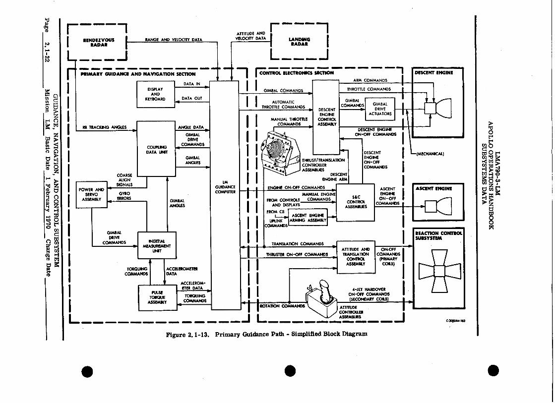
2. 1. 3. 1 Primary Guidance Path. (See figure 2.1-13.)
The primary guidance path comprises the PGNS, CES, LR, RR, and the selected propulsion section required to perform the desired maneuvers. The CES routes flight control commands from the PGNS and applies them to the descent or ascent engine, and/or the appropriate thrusters.
The IMU, which continuously measures attitude and acceleration, is the primary inertial sensing device of the vehicle. The LR senses slant range and velocity. The RR coherently tracks the CSM to derive LOS range, range rate, and angle rate. The LGC uses AOT star-sighting data to align U
GUIDANCE, NAVIGATION, AND CONTROL SUBSYSTEM Mission LM Basic Date 1 February 1970 Change Date 15 June 1970 Page 2. 01
ATTITUDE AND VELOCITY DATA
- MONO OM.
LANDING RADAR
DESCENT ENGINE
CONTROL ASSEMBLY
GIMBAL COMMAND GIMBAL
DRIVE ACTUATORS
THRUSTER ON-Off COMMANDS •
ENGINE ON-OFF COMMANDS
SIC CONTROL
ASSEMBLIES
ASCENT ENGINE
ON-OFF COMMANDS
ASCENT ENGINE MANUAL ENGINE
FROM CONTROLS COMMANDS AND DISPLAYS
FROMCSei
ASCENT ENGINE F.
UPLINK ARMING ASSEMBLY COMMANDS
OWE= 11111MMIP ,1■11111.1• 111.1
RENDEZVOUS I RADAR
L ONIONIO IIMM=1 11111.1•1111
r •111=11 MINIM =MIMI MEM. MIMI= =MID 11■11110 MINIM 1.11111■1 MOM MUM ■11111=
PRIMARY GUIDANCE AND NAVIGATION SECTION
DISPLAY AND
KEYBOARD DATA OUT
RR TRACKING ANGLES ANGLE DATA
COUPLING DATA UNIT
GIMBAL DRIVE
COMMANDS
GIMBAL ANGLES
• .16
COARSE ALIGN
SIGNALS
GYRO ERRORS
TORQUING COMMANDS
ACCELEROMETER DATA
DATA IN
POWER AND SERVO
ASSEMBLY GIMBAL ANGLES
GIMBAL DRIVE
COMMANDS INERTIAL MEASUREMENT
UNIT
PULSE TORQUE
ASSEMBLY
ACCELEROM-ETER DATA
TORQUING COMMANDS
J L.-
THRUST/TRANSLATION CONTROLLER ASSEMBLIES
DESCENT ENGINE ARM
ATTITUDE CONTROLLER
1111111111110 411111•10 41111111111110 IINEININO 01111111110 a ..J1 ASSEMBLES
ROTATION COMMANDS
RANGE AND VELOCITY DATA
DESCENT ENGINE ON-OFF COMMANDS
DESCENT ENGINE
(MECHANKAL)
C-3,JA41113
4-JET HARDOVER I ON-OFF COMMANDS
(SECONDARY COILS1_11......„
I AUTOMATIC THROTTLE COMMANDS
ell=111111 11111111•1111111 11111110•1110
.1
"NMI 011111■1 01111•11M MIMI= IMMO ONIINININ MINIM MINIM 11111111111111 MUM" MIMI ■11111
I CONTROL ELECTRONICS SECTION
I I GIMBAL COMMAND
I I
II
II
I 1 I I
IIII
II II I I I II II
DESCENT ENGINE ON-Off COMMANDS
TRANSLATION COMMANDS ATTITUDE AND TRANSLATION
CONTROL ASSEMBLY
ON-OFF I COMMANDS
(PRIMARY COILS)
REACTION CONTROL SUBSYSTEM
ARM COMMANDS
THROTTLE COMMANDS
LM GUIDANCE COMPUTER
LV Lsa
Figure 2.1-13. Primary Guidance Path - Simplified Block Diagram
• • •
LMA790-3-LM APOLLO OPERATIONS HANDBOOK
SUBSYSTEMS DATA
the IMU. Using inputs from the LR, IMU, RR, 'rTCA's, and ACA's, the LGC solves guidance, navigation, steering, and stabilization equations necessary to initiate on and off commands for the descent and ascent engines, throttle commands and trim commands for the descent engine, and on and off commands for the thrusters.
Control of the vehicle, when using the primary guidance path, ranges from fully automatic to manual. The primary guidance path operates in the automatic mode or the attitude hold mode. In the automatic mode, all navigation, guidance, stabilization, and control functions are controlled by the LGC. When the attitude hold mode is selected, the astronaut uses his ACA to bring the vehicle to a desired attitude. When the ACA is moved out of the detent position, proportional attitude-rate or minimum impulse commands are routed to the LGC. The LGC then calculates steering information and generates thruster commands that correspond to the mode of operation selected via the DSKY. These commands are applied to the primary preamplifiers in the ATCA, which routes the commands to the proper thruster. When the astronaut releases the ACA, the LGC generates commands to hold this attitude. If the astro- naut commands four-jet direct operation of the ACA by going to the hard over position, the ACA applies ■ the command directly to the secondary solenoids of the corresponding thruster.
In the automatic mode, the LGC generates descent engine throttling commands, which are routed to the descent engine via the DECA. The astronaut can manually control descent engine throttling with his TTCA. The DECA sums the TTCA throttle commands with the LGC throttle commands and applies the resultant signal to the descent engine. The DECA also applies trim commands, generated by the LGC, to the GDA's to provide trim control of the descent engine. The LGC supplies on and off com-mands for the ascent and descent engines to the S&C control assemblies. The S&C control assemblies route the ascent engine on and off commands directly to the ascent engine, and the descent engine on and off commands to the descent engine via the DECA.
In the automatic mode, the LGC generates +X-axis translation commands to provide ullage. In the manual mode, manual translation commands are generated by the astronaut, using his TTCA. These commands are routed, through the LGC, to the ATCA and on to the proper thruster.
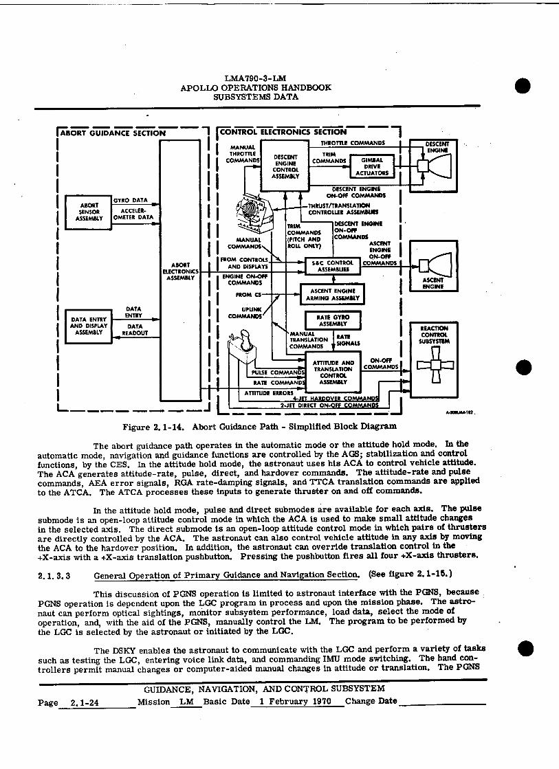
2.1.3.2 Abort Guidance Path. (See figure 2.1-14.)
The abort guidance path comprises the AGS, CES, and the selected propulsion section. The AGS performs all inertial navigation and guidance functions necessary to effect a safe orbit or rendezvous with the CSM. The stabilization and control functions are performed by analog computation techniques, in the CES.
The AGS uses a strapped-down inertial sensor, rather than the stabilized, gimbaled sensor used in the IMU. The ASA is a strapped-down inertial sensor package that measures attitude and acceler-ation with respect to the vehicle body axes. The ASA-sensed attitude is supplied to the AEA, which is a high-speed, general-purpose digital computer that performs the basic strapped-down system computations and the abort guidance and navigation steering control calculations. The DEDA is a general-purpose input-output device through which the astronaut manually enters data into the AEA and commands various data readouts.
The CES functions as an analog autopilot when the abort guidance path is selected. It uses inputs from the AGS and from the astronauts to provide the following: on, off, and TTCA throttling com-mands for the descent engine; gimbal commands for the GDA's to control descent engine trim; on and off III commands for the ascent engine; sequencer logic to ensure proper arming and staging before engine startup and shutdown; on and off commands for the thrusters for translation and stabilization, and for various maneuvers; jet-select logic to select the proper thrusters for the various maneuvers; and modes of vehicle control, ranging from fully automatic to manual.
The astronaut uses the TTCA to control descent engine throttling and translation maneuvers. The throttle commands, engine on and off commands from the S&C control assemblies, and trim com-mands from the ATCA are applied to DECA. The DECA applies the throttle commands to the descent engine, the engine on and off commands to the descent engine latching device, and the trim commands to the GDA's. The S&C control assemblies receive engine on and off commands for the descent and ascent engines from the AEA. As in the primary guidance path, the S&C control assemblies route descent engine commands to the DECA and apply ascent engine on and off commands directly to the ascent engine.
GUIDANCE, NAVIGATION, AND CONTROL SUBSYSTEM Mission LM Basic Date 1 February 1970 Change Date 15 June 1970 Page 2.1-23
2-JET DIRECT ON-OFF .111111•••■ .1=MNIMm .111••••■
LMA790-3-LM APOLLO OPERATIONS HANDBOOK
SUBSYSTEMS DATA • !MORT GUIDANCE SECTION 1 p NTROL ELECTRONICS SECTION
1 I I II I I
IIII
I FROAMNDCDOINSPIRLATS
I
I ENG
INE NDSFF
I FROM CS
I II
II
PULSE
THROTTLE COMMANDS
ABORT SENSOR
ASSEMBLY
DATA ENTRY AND DISPLAY
ASSEMBLY
GYRO DATA •••
ACCELER- OMETER DATA
DATA ENTRY
DATA READOUT
•
ABORT ELECTRONICS
ASSEMBLY
J L
I
MANUAL THROTTLE
COMMANDS
MANUAL COMMANDS
UPUNK COMMANDS
ATTITUDE ERRORS 4-JET HARDOVER
ATTITUDE AND TRANSLATION
CONTROL RATE COMMAND ASSEMBL
COMMANDS Fr: COMMANDS
DESCENT ENGINE
CONTROL ASSEMBLY
TRIM COMMANDS (PITCH AND ROLL ONLY)
MANUAL TRANSLATION COMMANDS
4 ASCENT ENGINE
ARMING ASSEMBLY
DESCENT ENGINE ON-OFF COMMANDS
THRUST/TRANSLATION CONTROLLER ASSEMBLIES
SEC CONTROL
TRIM COMMANDS
RATE GYRO ASSEMBLY
ASSEMBLIES
DESCENT ENGINE ON-OFF COMMANDS
ASCENT ENGINE ON-OFF
COMMANDS
RATE SIGNALS
COMPAANDS4
GIMBAL DRIVE
ACTUATORS
ON-OFF COMMANDSI
Y
I■ow REACTION CONTROL
SUBSYSTEM
ASCENT ENGINE
DESCENT ENGINE
A•300U04182
• Figure 2.1-14. Abort Guidance Path - Simplified Block Diagram
The abort guidance path operates in the automatic mode or the attitude hold mode. In the automatic mode, navigation and guidance functions are controlled by the AGS; stabilization and control functions, by the CES. In the attitude hold mode, the astronaut uses his ACA to control vehicle attitude. The ACA generates attitude-rate, pulse, direct, and hardover commands. The attitude-rate and pulse commands, AEA error signals, RGA rate-damping signals, and TTCA translation commands are applied to the ATCA. The ATCA processes these inputs to generate thruster on and off commands.
In the attitude hold mode, pulse and direct submodes are available for each axis. The pulse submode is an open-loop attitude control mode in which the ACA is used to make small attitude changes in the selected axis. The direct submode is an open-loop attitude control mode in which pairs of thrusters are directly controlled by the ACA. The astronaut can also control vehicle attitude in any axis by moving the ACA to the hardover position. In addition, the astronaut can override translation control in the +X-axis with a +X-axis translation pushbutton. Pressing the pushbutton fires all four +X-axis thrusters.
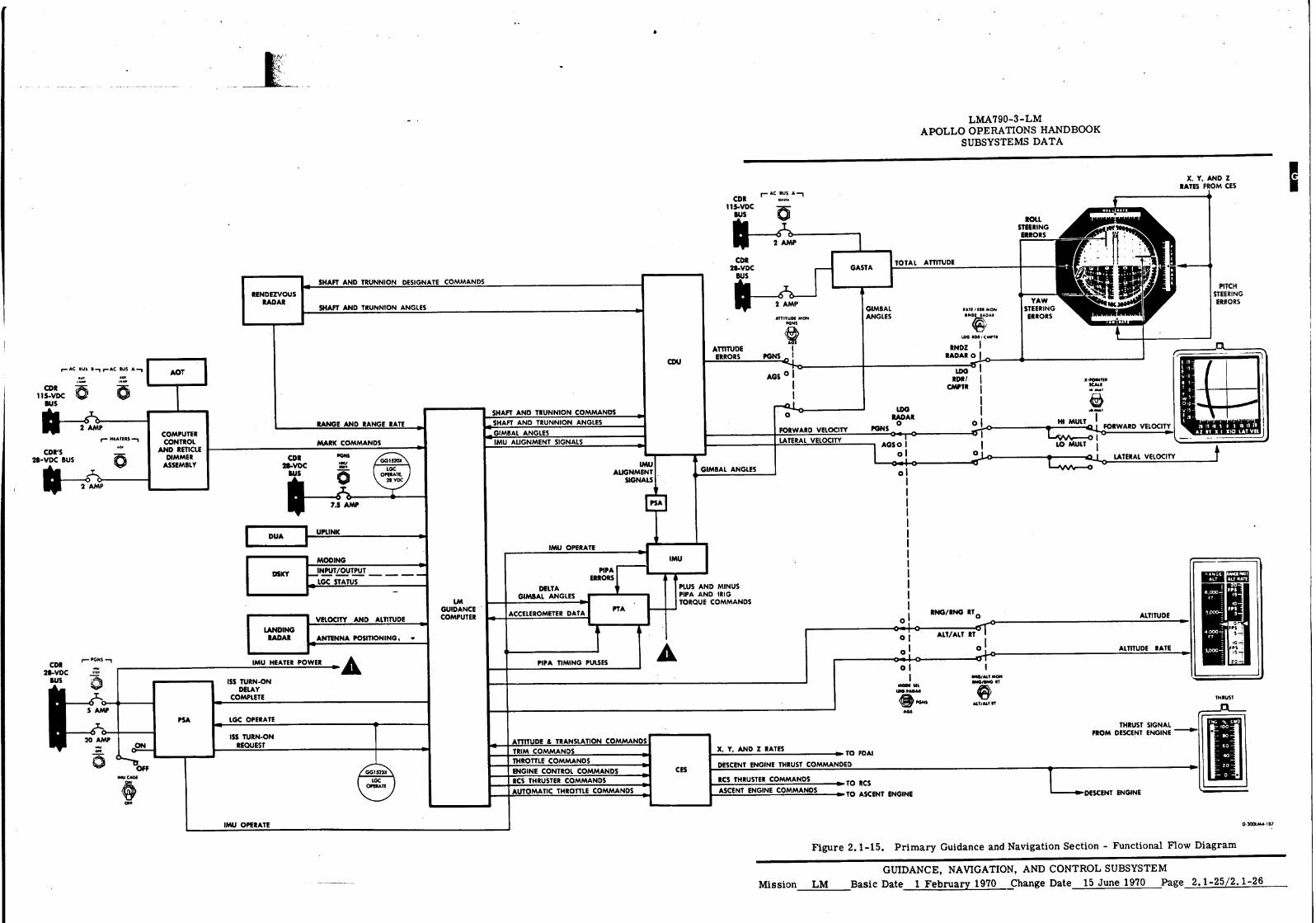
2.1.3.3 General Operation of Primary Guidance and Navigation Section. (See figure 2.1-15.)
This discussion of PGNS operation is limited to astronaut interface with the PGNS, because PGNS operation is dependent upon the LGC program in process and upon the mission phase. The astro-naut can perform optical sightings, monitor subsystem performance, load data, select the mode of operation, and, with the aid of the PGNS, manually control the LM. The program to be performed by the LGC is selected by the astronaut or initiated by the LGC.
The DSKY enables the astronaut to communicate with the LGC and perform a variety of tasks such as testing the LGC, entering voice link data, and commanding IMU mode switching. The hand con-trollers permit manual changes or computer-aided manual changes in attitude or translation. The PGNS
GUIDANCE, NAVIGATION, AND CONTROL SUBSYSTEM Page 2.1-24 Mission LM Basic Date 1 February 1970 Change Date
r- AC BUS A —1 CDR
115-VDC BUS
111--.261A 1)/AP
SHAFT AND TRUNNION DESIGNATE COMMANDS •R
CDR 28-VDC
BUS
2 AMP
ATTITUDE MON PONS
GASTA TOTAL ATTITUDE
RENDEZVOUS RADAR
SHAFT AND TRUNNION ANGLES GIMBAL ANGLES
NATI let MOM
INCI4ADAA
YAW STEERING
ERRORS
ROLL STEERING ERRORS
40 OW
NI MULT I 4.1 .0FORWARD VELOCITY.
LO MULT
LATERAL VELOCITY
040•11111 KALI 141 AIM
(1,9p
PITCH STEERING ERRORS
70 IS D 5 0 5 10 (5 20 AZ IT Xi 510 LAT VFL_
PTA
DELTA GIMBAL ANGLES
ACCELEROMETER DATA
20 AMP
•••
0 OFF DAY CAGE
r- PGNS CDR
28-VDC .• BUS
0
11--561:170--
0
CN
IMU HEATER POWER PIPA TIMING PULSES
PSA
ISS TURN-ON DELAY
COMPLETE
LGC OPERATE
1SS TURN-ON REQUEST ATTITUDE 8 TRANSLATION COMMANDS
X, Y, AND Z RATES ► TO FDAI
DESCENT ENGINE THRUST COMMANDED CES
RCS THRUSTER COMMANDS
ASCENT ENGINE COMMANDS TO RCS
im• TO ASCENT ENGINE
IMU I PLUS AND MINUS PIPA AND TRIG TORQUE COMMANDS
IMU OPERATE
LM GUIDANCE COMPUTER
PIPA ERRORS
nb GG1523X
LGC OPERAT1
AUTOMATIC THROTTLE COMMANDS
TRIM COMMANDS
THROTTLE COMMANDS
ENGINE CONTROL COMMANDS RCS THRUSTER COMMANDS
ALTITUDE RATE
ALTITUDE
L.....DESCENT ENGINE
THRUST SIGNAL FROM DESCENT ENGINE —II'
TER ANTENNA POSITIONING, •
DSKY
LANDING RADAR
MOOING
INPUT/OUTPUT
LGC STATUS
VELOCITY AND ALTITUDE RNO/ RHO RT
o
ALT/ALT RTCrr
0
EAKVAIT MON 11.11/11NO eT
(iN) ■
AlTiAll IT THRUS T
0
0 I o I O - 1 o 1
MODE Ill IBS PADAO
11-1•- ■ , PONS
'
•
LMA790-3-LM APOLLO OPERATIONS HANDBOOK
SUBSYSTEMS DATA
X. Y, AND Z RATES FROM CES
f— AC SUS I1 f— AC BUS A
rm.
CDR 115-VDC
BUS
11111-2,4 1)NIP r. MATERS
CDR'S *PI
28-VDC BUS
1141—i6LIA13
RANGE AND RANGE RATE
MARK COMMANDS
PONS
0
7.5 AMP
SHAFT AND TRUNNION COMMANDS SHAFT AND TRUNNION ANGLES
PSA
ATTITUDE ERRORS PONS
AGS °
• GIMBAL ANGLES
•
LOG RADAR 0
PONS 0 ' 0 1
AGS 0 0
0 0
COMPUTER CONTROL
AND RETICLE DIMMER
CDR ASSEMBLY
2$-VDC BUS
WO EDI cwt.
INOZ I RADAR .1010
LOG RDR /
CM? T R
O FORWARD VELOCITY
LATERAL VELOCITY
0015205
LOC OPERATE,
211 VDC
GIMBAL ANGLES IMU ALIGNMENT SIGNALS
IN
IMU ALIGNMENT
SIGNALS
DUA UPUNK
MU OPERATE O3COLAL• 187
Figure 2.1-15. Primary Guidance and Navigation Section - Functional Flow Diagram
GUIDANCE, NAVIGATION, AND CONTROL SUBSYSTEM Mission LM Basic Date 1 February 1970 Change Date 15 June 1970 Page 2.1-25/2.1-26
LMA790-3-LM APOLLO OPERATIONS HANDBOOK
SUBSYSTEMS DATA
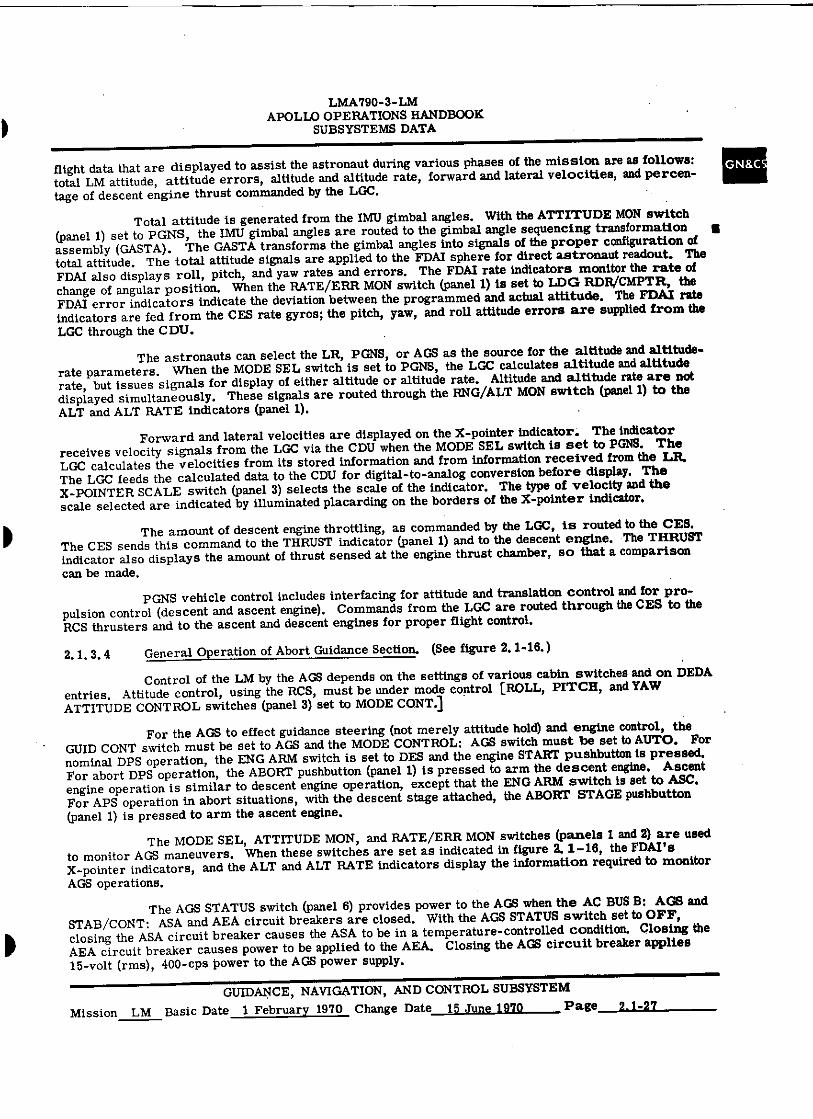
flight data that are displayed to assist the astronaut during various phases of the mission are as follows: total LM attitude, attitude errors, altitude and altitude rate, forward and lateral velocities, and percen-tage of descent engine thrust commanded by the LGC.
Total attitude is generated from the IMU gimbal angles. With the ATTITUDE MON switch (panel 1) set to PGNS, the IMU gimbal angles are routed to the gimbal angle sequencing transformation assembly (GASTA). The GASTA transforms the gimbal angles into signals of the proper configuration of total attitude. The total attitude signals are applied to the FDAI sphere for direct astronaut readout. The FDA! also displays roll, pitch, and yaw rates and errors. The FDAI rate indicators monitor the rate of change of angular position. When the RATE/ERR MON switch (panel 1) is set to LDG RDR/CMPTR, the FDAI error indicators indicate the deviation between the programmed and actual attitude. The FDAI rate indicators are fed from the CES rate gyros; the pitch, yaw, and roll attitude errors are supplied from the LGC through the CDU.
The astronauts can select the LR, PGNS, or AGS as the source for the altitude and altitude-rate parameters. When the MODE SEL switch is set to PGNS, the LGC calculates altitude and altitude rate, but issues signals for display of either altitude or altitude rate. Altitude and altitude rate are not displayed simultaneously. These signals are routed through the RNG/ALT MON switch (panel 1) to the ALT and ALT RATE indicators (panel 1).
Forward and lateral velocities are displayed on the X-pointer indicator. The indicator receives velocity signals from the LGC via the CDU when the MODE SEL switch is set to PGNS. The LGC calculates the velocities from its stored information and from information received from the LR. The LGC feeds the calculated data to the CDU for digital-to-analog conversion before display. The X- POINTER SCALE switch (panel 3) selects the scale of the indicator. The type of velocity and the scale selected are indicated by illuminated placarding on the borders of the X-pointer indicator.
The amount of descent engine throttling, as commanded by the LGC, is routed to the CES. The CES sends this command to the THRUST indicator (panel 1) and to the descent engine. The THRUST indicator also displays the amount of thrust sensed at the engine thrust chamber, so that a comparison can be made.
PGNS vehicle control includes interfacing for attitude and translation control and for pro-pulsion control (descent and ascent engine). Commands from the LGC are routed through the CES to the RCS thrusters and to the ascent and descent engines for proper flight control.
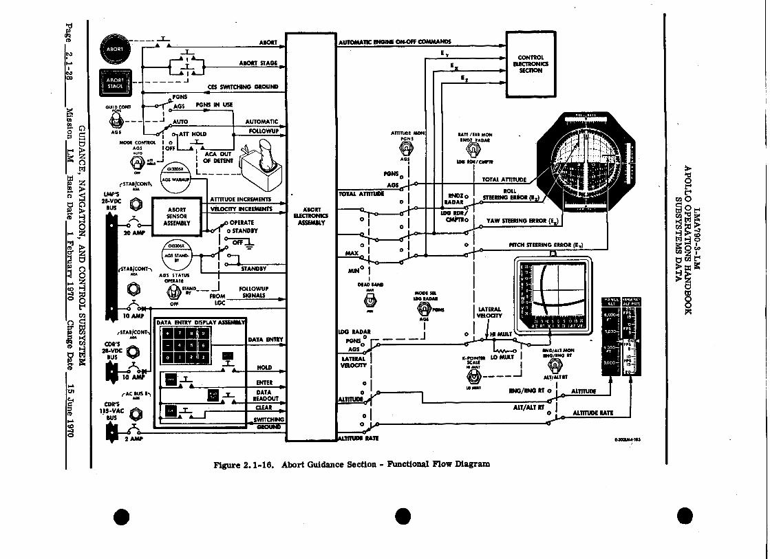
2.1. 3.4 General Operation of Abort Guidance Section. (See figure 2.1-16.)
Control of the LM by the AGS depends on the settings of various cabin switches and on DEDA entries. Attitude control, using the RCS, must be under mode control [ROLL, PITCH, and YAW ATTITUDE CONTROL switches (panel 3) set to MODE CONT.)
For the AGS to effect guidance steering (not merely attitude hold) and engine control, the GUID CONT switch must be set to AGS and the MODE CONTROL: AGS switch must be set to AUTO. For nominal DPS operation, the ENG ARM switch is set to DES and the engine START pushbutton is pressed. For abort DPS operation, the ABORT pushbutton (panel 1) is pressed to arm the descent engine. Ascent engine operation is similar to descent engine operation, except that the ENG ARM switch is set to ASC. For APS operation in abort situations, with the descent stage attached, the ABORT STAGE pushbutton (panel 1) is pressed to arm the ascent engine.
The MODE SEL, ATTITUDE MON, and RATE/ERR MON switches (panels 1 and 2) are used to monitor AGS maneuvers. When these switches are set as indicated in figure 2. 1-16, the FDA1's X-pointer indicators, and the ALT and ALT RATE indicators display the information required to monitor AGS operations.
The AGS STATUS switch (panel 6) provides power to the AGS when the AC BUS B: AGS and STAB/CONT: ASA and AEA circuit breakers are closed. With the AGS STATUS switch set to OFF, closing the ASA circuit breaker causes the ASA to be in a temperature-controlled condition. Closing the AEA circuit breaker causes power to be applied to the AEA. Closing the AGS circuit breaker applies 15-volt (rms), 400-cps power to the AGS power supply.
GUIDANCE, NAVIGATION, AND CONTROL SUBSYSTEM Mission LM Basic Date 1 February 1970 Change Date 15 June 1970 Page 2.1-27
--A •
ABORT
STAGE
Ti
STABICONTs ASA
LMP'S 2B-VDC
BUS
10 IL
AMP
ICONT iSTAB-N
20 AMP
*
et.
0-1.434- SAC BUS
Ms CDR'S
115-VAC BUS
ABORT SENSOR
ASSEMBLY
• (4,41.0 ON
Enna 1111111111 CM=
OPERATE 0 STANDBY
1 _
on STANDBY
1
LGC
1
1
1 LATERAL VELOCITY
I II MOLT .
LO /AULT I ■•POINTS SCALE NI MAI
rnea I o r_ A GS
—4:4#30 _
1 A1T4HOLD MODE co
AG S
I OFF ♦ , • ACA OUT
AIR I OF DEMO Rots
ABORT ELECTRONICS
ASSEMBLY
AGE / CA1111
PONS 1
AGS0 TOTAL ATTITUDE
RNDz 0 ROELRL
0 I RADAR ...A..41sTEER010 .02
LOG um// CM.W1Ro
*MN° II
DEAD RAND MODE SR
106 SAGAS
POEM
DATA ENTRY •
Mx_
ATTITUDE
AGS STATUS OPERATE
STAND_ FOLLOWUP sr
FROM SIGNALS
DATA ENTRY DISPLAY ASSEMBLY
• •
• •
RANGE ALT
.441
ALI RATE
70 IS IO S 5 tD 15 20 AZ IT X I X10 LAT VEL
ING/All AEON 11140/MMEG
140010A4410
Figure 2.1-16. Abort Guidance Section - Functional Flow Diagram
OL
6T a u
nt
gi
ova
oTgea
ri
uoT
ssiy
i
4-)
LI
4-)
0
m8
PT
0 4 0 0
cn
co ■-3 tzi
0 t-4
En 0
11 CD
tri
60 w cn
1 *3
CI
8
• •
LMA790-3- LM APOLLO OPERATIONS HANDBOOK
SUBSYSTEMS DATA
GN&CS Initial conditions for AGS operation require that the AGS STATUS switch be set to STANDBY, then to OPERATE. The time between closing the circuit breakers and setting the AGS STATUS switch to OPERATE should be 40 minutes; for at least the last 25 minutes, the switch should be set to STANDBY. Degraded performance is available after 10 minutes in the standby mode. When the AGS STATUS switch is set to OFF, the AEA has no functional capability. After 20 seconds in the standby mode, the AEA can accept the CDU zero signal and integrate the PGNS Euler angle changes. Complete AEA capability is afforded when the switch is set to OPERATE. In the operate mode, the AEA enters a core-priming routine that ensures that the memory is properly magnetized.
AGS operations are performed mainly through two DEDA addresses: 400 and 410. (Refer to Apollo Operations Handbook, Volume II, paragraph 4.4 for AGS selector logic list. ) Address 400 is the AGS submode selector; address 410, the guidance routine selector. The selected routine is computed every 2 seconds, regardless of the submode selected. The AGS does not respond to orient the LM in accordance with the routine selected, unless DEDA address 400 (mode selector) is set to +00000 (attitude hold), +10000 (guidance steering), or +20000 (Z-axis steering).
When the LM is under full. AGS control, the engine-on signal cannot be generated unless the guidance steering submode is selected. The engine-on signal is automatically generated after ullage has been sensed for three (DEDA-accessible constant) consecutive computer cycles (2 seconds per cycle). The AGS recognizes ullage to have occurred when the average acceleration in the +X-direction exceeds 0.1 fps2. (The average acceleration is DEDA-accessible.) The ASA (containing the accelerometers) is located ahead of the center of gravity (in the +X-direction). Therefore, LM rotations cause sensed accelerations in the -X-direction. For this reason, LM rotations cannot cause the AGE to sense that ullage has occurred.
When the LM is not under full AGS control (neither the ABORT nor ABORT STAGE push-button has been pressed, or the MODE CONTROL: AGS switch is not set to AUTO, or the GUID CONT switch is not set to AGS), the AGS issues engine commands (on or off) that duplicate actual engine ope ration.
Under full AGS control, the ascent or descent engine is automatically commanded off when the velocity to be gained in the +X-direction is less than the nominal ascent engine thrust decay velocity and if the total velocity to be gained is less than a prescribed threshold (a DEDA-accessible constant currently set at 100 fps). This dual check maintains the engine on if an abort occurs during powered flight with the LM incorrectly oriented for the abort maneuver and the velocity to be gained large (greater than the 100-fps threshold).
When the velocity to be gained (LM wider full AGS control) is less than 15 fps and the sensed thrust acceleration level in the +X-direction is greater than 0.1 fps h, the desired thrust direction is fixed in inertial space (a form of attitude hold). If this were not done, the LM desired attitude might go through an undesirably wide excursion in an attempt to achieve perfect velocity cutoff conditions. Large variations near the end of a maneuver are undesirable. The velocity cutoff errors incurred by fixing the desired attitude before engine cutoff are small. After the maneuver is completed, small cutoff errors can be removed (if desired) by the axis-by-axis velocity trim capability of the AGS.
The descent stage is staged (when the AGS is in control) by pressing the ABORT STAGE pushbutton. The staging sequence begins only when engine-on commands are issued. During a thrusting maneuver, the staging sequence begins immediately upon pressing the ABORT STAGE pushbutton (assum-ing that all panel controls that transfer control of the LM to the AGS have been set properly). The AGS senses sufficient average thrust acceleration throughout the staging maneuver to maintain ullage. When the AGS receives verification from the CES that the ascent engine is on, the AGS automatically enters the attitude hold submode. After a prescribed interval, between zero and 10 seconds (DEDA-controlled, presently set at 1 second), the ACE automatically enters the normal guidance steering submode.
When the PGNS controls the LM (GUID CONT switch set to PGNS), the AGS is in the followup mode. Manual control of the LM by the astronauts (MODE CONTROL: PGNS switch set to ATT HOLD, attitude controller out of detent) also causes the followup signal to be routed to the AGS. In the followup mode, the AGS follows the PGNS by routing engine commands (on or off) in accordance with ascent or descent engine operation and provides zero attitude control error signals. The AGS provides attitude error signals (corresponding to the AEA guidance solutions) for the FDAI's when the PGNS is in control, the MODE CONTROL: PGNS switch is set to AUTO, the ATTITUDE MON switch is set to AGS, and the RATE/ERR MON switch is set to LDG FtDR/CMPTR,
GUIDANCE, NAVIGATION, AND CONTROL SUBSYSTEM Mission LM Basic Date 1 February 1970 Change Date 15 June 1970 Page 2.1-29
LIVIA790-3-LM APOLLO OPERATIONS HANDBOOK
SUBSYSTEMS DATA
2.1.3.5 General Operation of the Control Electronics Section.
The PGNS, in conjunction with the CES, provides automatic control of LM attitude, transla-tion, and descent or ascent propulsion maneuvers. Automatic control can be overridden by the astronauts, with manual inputs. As backup for PGNS control, the AGS, supplemented by manual inputs, can be used if the PGNS malfunctions. Table 2.1-1 contains a summary of the CES modes of attitude control.
2.1.3.5.1 Attitude Control. (See figure 2.1-17.)
LM attitude is controlled by X, Y, and Z axes. There are five modes of attitude control: automatic, attitude hold, pulse, direct, and hardover (manual override). The automatic and attitude hold modes are selected with the MODE CONTROL: PGNS or AGS switch; the pulse and direct modes, with the ATTITUDE CONTROL: ROLL, PITCH, and YAW switches.
Automatic Mode. The automatic mode provides fully automatic attitude control. During PGNS control, the LGC generates the required thruster commands and routes them to the ATCA. The jet drivers in the ATCA provide thruster on and off commands to selected RCS primary solenoids for attitude changes. In the abort guidance mode, roll, pitch, and yaw attitude error signals are generated in the AGS and sent to the ATCA. These error signals are passed through limiters and then are combined with damping signals from the RGA, demodulated, passed through selectable deadband circuits, jet select logic circuits, PRM's and jet driver amplifiers, which fire the RCS jets. The jet select logic determines which jets fire to correct the attitude errors. In the primary and abort guidance modes, the astronaut can override attitude control about all three LM axes by initiating hardover commands with the ACA.
Attitude Hold Mode. This is a semiautomatic mode, in which either astronaut can command an attitude change at an angular rate proportional to ACA displacement. LM attitude is held when the ACA is In the detent (neutral) position. In the primary guidance mode, rate commands proportional to ACA displace-ment are sent to the LGC. The LGC operates on these commands and provides signals to the jet drivers in the ATCA to command rotation rates by means of the thrusters. When the ACA is returned to the neutral position, LM rotation stops and the LGC maintains the new attitude. In the abort guidance mode, with the ACA in the neutral position, LM attitude is held by means of AGS error signals. When an ACA is moved out of the detent position, the attitude error signals from the AGS are set to zero. Rate com-mands proportional to ACA displacement are processed in the ATCA, and the thrusters are fired until the desired vehicle rate is achieved. When the ACA is returned to the detent position, the vehicle rate is reduced to zero and the AGS holds the LM in the new attitude.
Pulse Mode. The pulse mode (minimum impulse control) is selected by a DSKY entry (verb 78) when the PGNS is in control and operating in the attitude hold mode. For minimum impulse control, the LGC commands a minimum impulse burn for each movement of the ACA beyond 2.5 ° of the detent position. The ACA must be momentarily returned to the detent position between each impulse command; The maximum rate at which minimum impulses can be commanded is approximately five per second. In this mode, the astronaut performs rate damping and attitude steering. When the AGS is in control, the pulse mode is an open-loop mode. It is selected on an individual-axis (roll, pitch, and yaw) basis by setting the appropriate ATTITUDE CONTROL switch (ROLL, PITCH or YAW) to PULSE. When the pulse mode is selected, automatic attitude control about the selected axis is disabled and a fixed train of pulses is generated when the ACA is displaced. To change attitude in this mode, the ACA must be moved past 2. 5 °
from detent; this commands acceleration about the selected axis. To terminate LM rotation, an opposite acceleration about the same axis must be commanded.
Direct Mode. The direct mode is also an open-loop acceleration mode. It is selected on an individual-axis basis by setting the appropriate ATTITUDE CONTROL switch (ROLL, PITCH or YAW) to DIR. Automatic AGS attitude control about the selected axis is disabled and direct commands to two thrusters are routed to the RCS secondary solenoids when the ACA is displaced 2.5 ° . The thrusters fire con-tinuously until the ACA is returned to the detent position.
Hardover Mode. In an emergency, the ACA can be displaced to the maximum limit (hardover position) to command an immediate attitude change about any axis. This displacement applies signals directly to the RCS secondary solenoids to fire four thrusters. This maneuver can be implemented in any attitude control mode.
Page 2.1-30 GUIDANCE, NAVIGATION, AND CONTROL SUBSYSTEM
Mission LM Basic Date 1 February 1970 Change Date
•
•

LMA790-3-LM APOLLO OPERATIONS HANDBOOK
SUBSYSTEMS DATA
Table 2.1-1. Control Electronics Section - Summary of Modes of Attitude Control
Mode
_ Switches and Positions
Guidance Signals
Manual Attitude Control
Manual Translation Control
Attitude . Damping
Engine Gimbal Control Remarks
Automatic MODE CONTROL: PGNS sw - Automatic steering N/A Linear translation of Accomplished Pitch and roll gimbal All thruster commands from LGC go (PGNS AUTO and translation are (See remarks LM by on-and-off in LGC commands from LGC directly to primary preamplifiers. control) GUM CONT sw - PGNS performed by LGC for manual firing of thrusters applied to DECA Attitude control function is over-
ATTITUDE CONTROL: ROLL, PITCH, and YAW sw - MODE CONT (normally)
commands to jet drivers.
override) when TTCA is moved out of detent
ridden by operating ACA to hardover position, thereby commanding on-and-off four-jet operation through secondary coils of thruster solenoid valves. +X-axis translation is obtained by commanding four-jet operation direct to RCS secondary coils, by pressing +X TRANSL pushbutton on panel S.
- - Attitude MODE CONTROL: PONS sw - Stabilization is Attitude rate Linear translation of Accomplished Pitch and roll gimbal Same as for automatic mode (PONS hold ATT HOLD accomplished by commands are LM by on-and-off in LGC commands from LGC control). Minimum impulse mode (PONS GUID CONT sw - PONS LGC commands proportional to firing of thrusters applied to DECA is made available by entering com- control) ATTITUDE CONTROL: ROLL,
PITCH, and YAW sw - MODE CONT (normally)
to jet drivers. ACA displace- ment. LM atti- hide is held to value when ACA is returned to detent.
when TTCA is moved. mend into DSKY. In this mode, LGC commands one RCS pulse each time ACA is moved past 2.5" nominally from detent.
Automatic MODE CONTROL: AGS sw - Automatic steering • N/A Linear translation of Rate gyro Pitch and roll gimbal AU thruster commands go through (AGS AUTO signals from AGS (See remarks LM by on-and-off signals sum- commands derived ATCA jet select logic and PRM. Atti- control) GUM CONT sw - AGS are sent to CES to for manual firing of thrusters med with from ATCA summed tude control function is overridden by
ATTITUDE CONTROL: ROLL, PITCH, and YAW sw - MODE CONT
command changes in LM attitude.
override) when TTCA is moved. steering signals
error channels operating ACA to hardover position, thereby commanding on-and-off four-jetoperation through secondary coils of thruster solenoid valves andbypass-ing jet select logic, PRM's, and jet drivers. +X-aids translation is obtained by commanding four-jet operation direct to RCA secondary coils, by pressing
- +X TRANSL pushbutton. 2 or 4 jet op-eration on single axis basis optional for pitch or roll and X-trtmslation with no MPS power. High and low gain rate
'depends on ascent/descent condition. • 1
Attitude ' MODE CONTROL: AGS sw - Automatic sta- Applied attitude Translation coo- Rate gyro Pitch and roll gimbal Same as for automatic mode (AGS hold ATT HOLD bilization signals, rate commands mends along LM signals sum- commands derived control). High and low gain rate (AGS GUM CONT sw - AGS which maintain are proportional axes by on-and-off med with from ATCA summed depends on ascent/descent condition. control) ATTITUDE CONTROL: ROLL,
PITCH, and YAW sw - MODE CONT
LM attitude. to ACA displace- meat: LM atti- tude is held to acquired value when ACA is re-turned to detent.
firing of thrusters when TTCA is moved out of detent
stabilization signals
error channels .
Pulse MODE CONTROL: AGS sw - . Abort guidance Astronaut coin- Translation coin- No rate damp- No AGS control Same as for automatic mode AUTO or ATT HOLD signals interrupted mends angular mands along LM ing in (Ws (AGS control) GUM CONT sw - AGS ATTITUDE CONTROL: ROLL, PITCH, and YAW sw - PULSE (selected on individual- axis basis)
on individual-axis basis.
acceleration through low- frequency pals- ing of thrusters (two jets).
axes by on-and-off firing of thrusters when TTCA is moved out of detent
selected .
.
GUIDANCE, NAVIGATION, AND CONTROL SUBSYSTEM Mission LM Basic Date 1 February 1970 Change Date Page 2.1-31
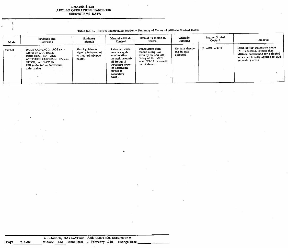
LMA79 0- 3- LM APOLLO OPERATIONS HANDBOOK
SUBSYSTEMS DATA
Table 2.1 - 1. Control Electronics Section - Summary of Modes of Attitude Control (coat)
Mode Switches and
Positions Guidance
Signals Manual Attitude
Control Manual Translation
Control Attitude Damping
Engine Gimbal Control Remarks
Direct MODE CONTROL: AGS sw - Abort guidance Astronaut corn- Translation corn- No rate damp- No AGS control Same as for automatic mode AUTO or ATT HOLD signals interrupted mands angular mands along LM ing in axis (AGS control), except that GUID CONT sw - AGS on individual-axis acceleration axes by on-and-off selected attitude commands for selected ATTITUDE CONTROL: ROLL, PITCH, and YAW sw - DIR (selected on individual- axis basis)
basis, through on-and- off firing of thrusters (two- jet operation direct to
coils).
firing of thrusters when TTCA is moved out of decent
secondary
axis are directly applied to RCS secondary coils
GUIDANCE, NAVIGATION, AND CONTROL SUBSYSTEM Page 2.1-32 Mission LM Basic Date 1 February 1970 Change Date
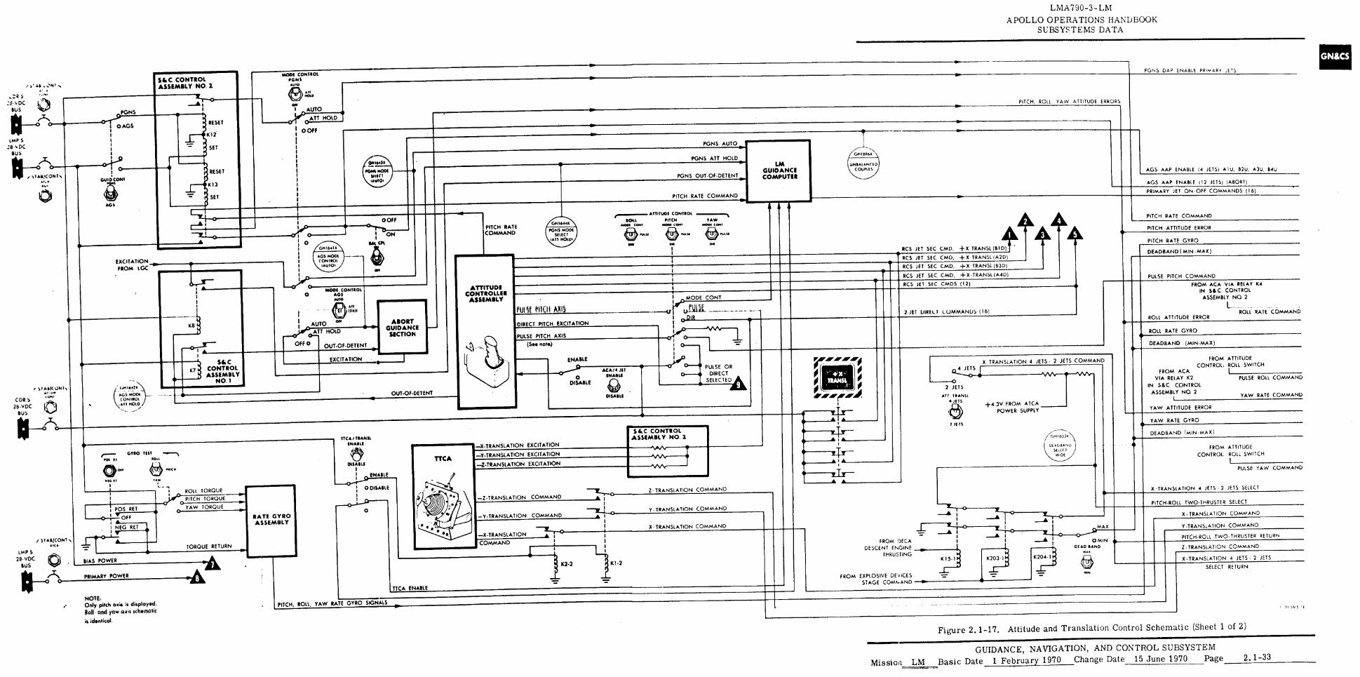
• AS , N I A
MODS CONTROL PGNS AUTO
Sim C CONTROL ASSEMBLY NO. 2 PGNS DAP ENABLE PRIMARY JETS
AT! TRANSL 4 1ET5
2 JE TS
2 JETS
• •
• • Tr- • •
DEADBAND (MIN-MAX)
FROM ATTITUDE CONTROL: ROLL SWITCH
FROM ACA VIA RELAY K2 PULSE ROLL COMMAND
IN S&C CONTROL ASSEMBLY NO 2
YAW RATE COMMAND
YAW ATTITUDE ERROR
YAW RATE GYRO
DEADBAND (MIN-MAX)
FROM ATTITUDE
CONTROL. ROLL SWITCH
PULSE YAW COMMAND
X TRANSLATION 4 JETS • 2 JETS SELECT
PITCH-ROLL TWO-THRUSTER SELECT
X TRANSLATION COMMAND
Y-TRANSLATION COMMAND
7
PITCH ROLL TWO-THRUSTER RETURN
Z TRANSLATION COMMAND
% TRANSLATION 4 JETS 2 JETS
SELECT RETURN
NOTE, Only pitch axis is displayed.
Red and ynw-axii idiomatic is identical.
PITCH, ROLL, YAW RATE GYRO SIGNALS
LMA790-3-- LM
APOLLO OPERATIONS HANDBOOK SUBSYSTEMS DATA
X TRANSLATION 4 JETS • 2 JETS COMMAND
+4.3V FROM ATCA POWER SUPPLY
//4:1N 603
UT AtASANU
ST11(1
WIDE
...7/67—c—Th 1 0 __.6 z IL I 0 I --•
A i ---AT
FROM DECA I I --• 1
DESCENT ENGINE 4-- THRUSTING
K15-1 K203.1 K204-1::
FROM EXPLOSIVE DEVICES STAGE COMMAND •
MAX
0 MIN DEAD RAND
PITCH, ROLL YAW ATTITUDE ERRORS
PGNS AUTO
GM11396x.
RESET
Kli
SET
RESET
K13
SET
UNBALANCED COUPLES
PONS OUT-OF•DETENT
0110•434
ROTA NODE VITO 461E10 1
PGNS ATT HOLD —0 0
• 11 140l0
-0
AGS AAP ENABLE 14 JETS) MU, B2U. A3U, EMU
(u)
LM GUIDANCE COMPUTER
AGS AAP ENABLE 112 JETS) (ABORT)
PITCH -RATE COMMAND AGS PRIMARY JET ON•OEF COMMANDS (16)
PGNS
eP""r9 I OATS
GUID CONI
I
•
AUTO
0,410P0 ATTHOLD
D OFF
S v DC
BUS
L/AP S 28ADC
BUS
11--- f )1A11/CONT,
• 1.,
0
RCS JET SEC CMD, +X TRANSL (BID)
RCS JET SEC CMD, + X TRANSL (A2D)
RCS JET SEC CMD, +X TRANSL (B3D)
I ON
GAS CPL OM
INTM • $1?) 0
DOFF
EXCITATION FROM LOC
,,,■■■■■.4,. ATTITUDE CONTROL
ROLL PITCH VAw MOOT COAT MOOT GUAM MOOT Com1 0 NAM
IN.
PITCH RATE COMMAND
PITCH RATE COMMAND
PITCH ATTITUDE ERROR
PITCH RATE GYRO
DEADBAND ( MIN •MAX)
0- RCS JET SEC CMD, + X TRANSL (A4D) PULSE PITCH COMMAND
RCS JET SEC CMDS (12) 0 ATTITUDE
CONTROLLER ASSEMBLY
MOOS CONTROL AG, AuI0
• 11
,11 11l5t PIIDI AXIS 2-1E1 UIREU COMMANDS (16)
KB ROLL RATE COMMAND DIRECT PITCH EXCITATION • le ROLL ATTITUDE ERROR
PULSE PITCH AXIS
ABORT GUIDANCE
SECTION ROLL RATE GYRO
(Soo note)
AUTO
G ATT HOLD
OFF 0 OUT-OF-DETENT Os
FROM ACA VIA RELAY K4 IN SIC CONTROL
ASSEMBLY NO 2
L.
I MODE CONY .001
o-22
ENABLE
0 DISABLE
K7
Ac.5 MODEC ON ROL
.•11 HOLD CDR S
28•vDC BUS
DISASLE
ACA/4 LIT IMAM
EXCITATION
r AII/4 ON I, An 0A. kam.
S&C CONTROL ASSEMBLY
NO. 1
OUT-OF-DETENT
Cel4P°"—•• PULSE OR 0-0 DIRECT
SELECTED
—X.TRANSLATION EXCITATION
TTCA/TRANSL I No, IL 1
• —Y-TRANSLATION EXCITATION TTCA —Z-TRANSLATION EXCITATION MARLS
ENABLE
0 DISABLE
SIC CONTROL ASSEMBLY NO. 2
2- TRANSLATION COMMAND ROLL TORQUE
O piTCH TORQUE
YAW TORQUE 0 y • TRANSLATION COMMAND RATE GYRO ASSEMBLY
X • TRANSLATiON COMMAND
• TORQUE RETURN
eC K2.2 K1 -2
-AA
TTCA ENABLE
GYRO .01 II
040
NIG TI
C7: OFF • ---
! POS RET
NEG RET • I v---•
± 1 0
•
BIAS POWER
PRIMARY POWER
— Z-TRANSLATION COMMAND
—Y•TRANSLATION COMMAND
—X-TRANSLATION COMMAND
r ST ACCON1 • ■ c•
IMP S 2P•VDC
BUS
IF\
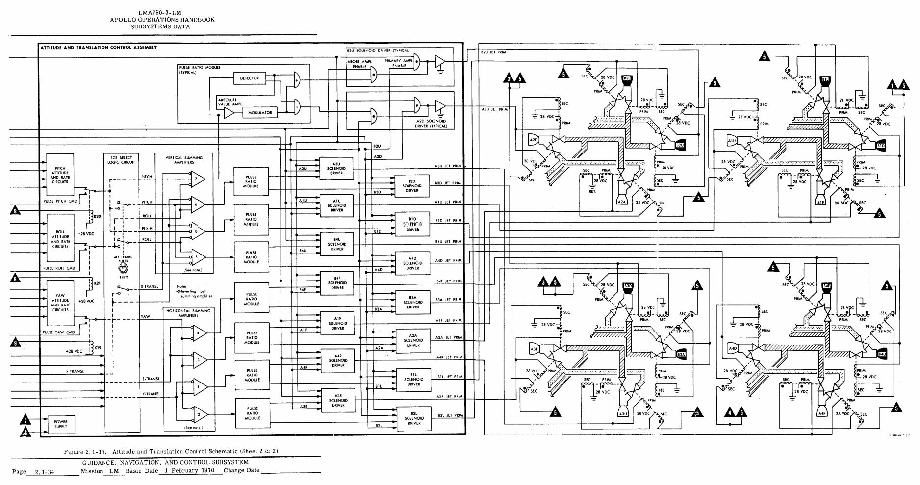
LMA790-3- LM APOLLO OPERATIONS HANDBOOK
SUBSYSTEMS DATA
ATTITUDE AND TRANSLATION CONTROL ASSEMBLY 82U SOLENOID DRIVER (TYPICAL) B2U JET PRIM
PRIMARY AMPL ENABLE
ABORT AMPL ENABLE
• PULSE RATIO MODULE (TYPICAL) •
SEC 28 VDC
•
PRIM
SEC DETECTOR
28 VDC
• f _
• SEC
PRIM SEC
PRIM
ABSOLUTE VALUE AMPS
4■8 SEC SEC
A2D JET PRIM MODULATOR
-7: 28 VDC — 28 VDC • • A2D SOLENOID
DRIVER (TYPICAL) PRIM PRIM
p • •
B2U
• A2D RCS SELECT LOGIC CIRCUIT
VERTICAL SUMMING AMPLIFIERS 28 VDC
• 28 VDC
• PRI PRIM
28 VOC
SEC •
28 VDC SEC
A3U SOLENOID
DRIVER
• A3U
A3U JET PRIM PRIM PITCH ATTITUDE
AND RATE CIRCUITS
SEC PRIM V • ■ PITCH PULSE RATIO
MODULE
• 28 VOC 7 SEC SEC SIC
• B3D
SOLENOID DRIVER
83D JET PRIM
PRIM B3D A- 1U MU
SC LENOID DRIVER
PULSE PITCH CMD A I U JET PRIM PITCH
ROLL
PIIL.H
ROLL
28 VDC SEC
•
6
PULSE RATIO
METpI lIE
K20 BID
§01 € NOID DRIVER
BID JET PRIM
8 BID ROLL +28 VDC ATTITUDE
AND RATE CIRCUITS T-4)
ROLL CMD E —C
B4U SOLENOID
DRIVER
B4U JET PRIM
84U PULSE RATIO
MODULE ----C 5
(See note.)
A4D SOLENOID
DRIVER
A4D JET PRIM
PULSE A4D •
• • • 11 TS • SEC /
1.111.3 28 VDC •
PRIM
114F SOLENOID
DRIVER
84F JET PRIM X21 SEC 28 VDC
•
B3D X.TRANSI. Note: -0-Inverting input
summing amplifier. •
54F PULSE RATIO
MODULE
YAW ATTITUDE +28 VDC
AND RATE CIRCUITS
A B3A SOLENOID
DRIVER
PRIM f- B3A JET PRIM
B3A HORIZONTAL SUMMING AMPLIFIERS
SEC SEC YAW
-
YAW CMD CMD
Al F SOLENOID
DRIVER
Alf JET PRIM Ins 28 VDC
PRIM
- 28 VDC •
A I F PRIM • PULSE PULSE RATIO
MODULE
A2A SOLENOID
DRIVER
A2A JET PRIM
+28 VDC j K19 11:1141■ Ar
• A2A
A4R SOLENOID
DRIVER
A412 JET PRIM
Yr sin AIR
PULSE RATIO
MODULE
28 VDi X TRANSL PRIM II IL SOLENOID
DRIVER
B1L JET PRIM Z TRANSL SEC PRIM rxzr-a-1 - • •
28VDC
SEC PRIM • •
28 VDC B1 L
SEC SEC Y.TRANSL A3R
SOLENOID DRIVER
ten A3R JET PRIM PRIM A3R
PULSE RATIO
MODULE 82L
SOLENOID DRIVER
B2L JET PRIM
POWER SUPPLY B2L
•
4
U1((11).1.1.51
Figure 2.1-17. Attitude and Translation Control Schematic (Sheet 2 of 2)
GUIDANCE, NAVIGATION, AND CONTROL SUBSYSTEM Mission LM Basic Date 1 February 1970 Change Date Page 2,1-34
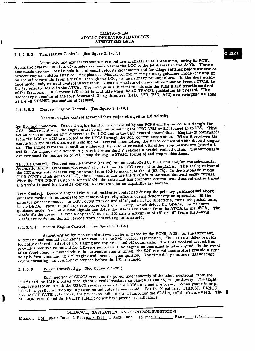
LMA790-3-LM APOLLO OPERATIONS HANDBOOK
SUBSYSTEMS DATA
2, 1.3.5, 2 Translation Control. (See figure 2. 1-17.)
Automatic and manual translation control are available in all three axes, using the RCS. Automatic control consists of thruster commands from the LGC to the jet drivers in the ATCA. These commands are used for translations of small velocity increments and for ullage settling before ascent or descent engine ignition after coasting phases. Manual control in the primary guidance mode consists of on and off commands from a TTCA, through the LGC, to the primary preamplifiers. In the abort guid-ance mode, only manual control is available. Control consists of on and off commands from a TTCA to the jet selected logic in the ATCA. The voltage is sufficient to saturate the PRM's and provide control of the thrusters. RCS thrust (+X-axis) is available when the +X TRANSL pushbutton is pressed. The secondary solenoids of the four downward-firing thrusters (BID, A2D, B3D, A4D) are energized as long as the +X TRANSL pushbutton is pressed.
2. 1. 3. 5. 3 Descent Engine Control. (See figure 2.1-18.)
Descent engine control accomplishes major changes in LM velocity.
Ignition and Shutdown. Descent engine ignition is controlled by the PGNS and the astronaut through the CES. Before ignition, the engine must be armed by setting the ENG ARM switch (panel 1) to DES. This action sends an engine arm discrete to the LGC and to the S&C control assemblies. Engine-on commands from the LGC or AGS are routed to the DECA through the S&C control assemblies. When it receives the engine arm and start discretes from the S&C control assemblies, the DECA commands the descent engine on. The engine remains on until an engine-off discrete is initiated with either stop pushbutton (panels 5 and 6), An engine-off discrete is generated when the A V reaches a predetermined value. The astronauts can command the engine on or off, using the engine START (panel 5) and stop pushbuttons.
Throttle Control. Descent engine throttle (thrust) can be controlled by the PGNS and/or the astronauts. Automatic throttle (increase/decrease) signals from the LGC are sent to the DECA. The analog output of the DECA controls descent engine thrust from 10% to maximum thrust (92. 5%). In the automatic mode (THR CONT switch set to AUTO), the astronauts can use the TTCA's to increase descent engine thrust. When the THR CONT switch is set to MAN, the astronaut has complete control over descent engine thrust. If a TTCA is used for throttle control, X-axis translation capability is disabled.
Trim Control. Descent engine trim is automatically controlled during the primary guidance and abort guidance modes, to compensate for center-of-gravity offsets during descent engine operation. In the primary guidance mode, the LGC routes trim on and off signals in two directions, for each gimbal axis, to the DECA. These signals operate power control circuitry, which drives the GDA's. In the abort guidance mode, Y- and Z-axis signals that drive the GDA's are routed from the ATCA to the DECA. The GDA's tilt the descent engine along the Y-axis and Z-axis a maximum of +6 ° or -6 ° from the X-axis. GDA's are activated during periods when descent engine is armed.
2. I. 3. 5.4 Ascent Engine Control. (See figure 2.1-19. )
Ascent engine ignition and shutdown can be initiated by the PGNS, AGS, or the astronaut. Automatic and manual commands are routed to the S&C control assemblies. These assemblies provide logically ordered control of LM staging and engine on and off commands. The S&C control assemblies provide a positive command for fail-safe purposes if the engine-on command is interrupted. In the event of an abort stage command while the descent engine is firing, the S&C control assemblies provide a time delay before commanding LM staging and ascent engine ignition. The time delay ensures that descent engine thrusting has completely stopped before the LM is staged.
2.1.3. 6 Power Distribution. (See figure 2.1-20.)
Each section of GN&CS receives its power independently of the other sections, from the CDR's and the LMP's buses through the circuit breakers on panels 11 and 16, respectively. The flight displays associated with the GN&CS receive power from CDR's a-c and d-c buses. When power is sup-plied to a particular display, a power-on indicator is energized. For the X-pointer, THRUST, RANGE, and RANGE RATE indicators, the power-on indicator is a lamp; for the FDAI's, talkbacks are used. The MISSION TIMER and the EVENT TIMER do not have power-on indicators.
GUIDANCE, NAVIGATION, AND CONTROL SUBSYSTEM Mission LM Basic Date 1 February 1970 Change Date 15 June 1970 Page 2.1-35
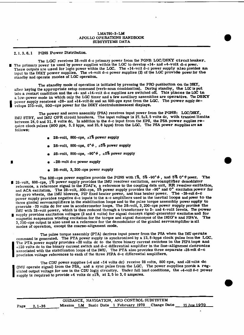
LMA790-3-LM APOLLO OPERATIONS HANDBOOK
SUBSYSTEMS DATA
2. 1. 3. 6. 1 PINS Power Distribution.
The LGC receives 28-volt d-c primary power from the PGNS: LGC/DSKY circuit breaker. II The primary power is used by power supplies within the LGC to develop +14- and +4-volt d-c power. -
These outputs are used for logic power within the LGC. The +14-volt d-c power supply also provides an input to the DSKY power supplies. The +4-volt d-c power supplies (2) of the LGC provide power for the standby and operate modes of LGC operation.
The standby mode of operation is initiated by pressing the PRO pushbutton on the DSKY, after keying the appropriate setup command (verb-noun combination). During standby, the LGC is put into a restart condition and the +4- and +14-volt d-c supplies are switched off. This places the LGC in a low-power mode in which only the LGC timer and a few auxiliary assemblies are operative. The DSKY power supply receives +28- and +14-volt dc and an 800-pps sync from the LGC. The power supply de-velops 275-volt, 800-cps power for the DSKY electroluminescent displays.
The power and servo assembly (PSA) receives input power from the PGNS: LGC/DSKY, IMU STBY, and IMU OPR circuit breakers. The input voltage is 27. 5±2. 5 volts dc, with transient limits between 24.0 and 31. 8 volts dc. In addition to the d-c input from the EPS, the PSA power supplies re-quire clock pulses (800 pps, 3.2 kpps, and 25.6 kpps) from the LGC. The PSA power supplies are as follows:
• 28-volt, 800-cps, *1% power supply
• 28-volt, 800-cps, 0 ° 0 , *5% power supply
• 28-volt, 800-cps, -90 ° 0 , ±5% power supply
■ • -28-volt d-c power supply
• 28-volt, 3, 200-cps power supply
The 800-cps power supplies provide the PGNS with 1%, 5% -90 ° 0 , and 5% 0° 4, power. The II 28-volt, 800-cps, 1% power supply provides the IMU resolver excitation, servoamplifier demodulator
reference, a reference signal to the FDAlts, a reference to the coupling data unit, RR resolver excitation, and ACA excitation. The 28-volt, .800-cps, 5% power supply provides the -90° and 0 ° excitation power for the gyro wheels, the IMU blowers, PIP fixed heater power, and bias heater power. The -28-volt d-c power supply provides negative d-c inputs to the a-c amplifiers used in the inertial loops and power to the three gimbal servoamplifiers in the stabilization loops and to the pulse torque assembly power supply to generate -20 volts de for use in accelerometer loops. The 28-volt, 3, 200-cps power supply provides the IMU with 28-volt power, which is then reduced through a transformer to 2- and 4-volt levels. The power
I supply provides excitation voltages (2 and 4 volts) for signal ducosyn signal-generator excitation and for magnetic suspension winding excitation for the torque and signal ducosyns of the IRIG' a and PIPA's. The 3, 200-cps output is also used as a reference for the demodulator of the gimbal servoamplifier in all modes of operation, except the coarse-alignment mode.
The pulse torque assembly (PTA) derives input power from the PSA when the IMU operate command is generated. The PTA power supply is synchronized by a 12. 8-kpps clock pulse from the LGC.
IThe PTA power supply provides +20 volts de to the three binary current switches in the PIPA loops and +120 volts de to the binary current switch and d-c differential amplifier in the fine-alignment electronics associated with the stabilization loops of the IMU. The PTA also provides three separate +28-volt d-c precision voltage references to each of the three PIPA d-c differential amplifiers.
The CDU power. supplies (+4 and +14 volts dc) receive 28 volts, 800 cps, and +28 volts de (IMU operate signal) from the PSA, and a sync pulse from the LGC. The power supplies provide a reg- ulated output voltage for use in the CDU logic circuitry. Under full load conditions, the +4-volt d-c power supply is required to provide +4 volts dc ±1%, at 2. 5 to 3. 0 amperes.
Page 2.1-36 GUIDANCE, NAVIGATION, AND CONTROL SUBSYSTEM
Mission LM Basic Date 1 February 1970 Change Date 15 June 1970
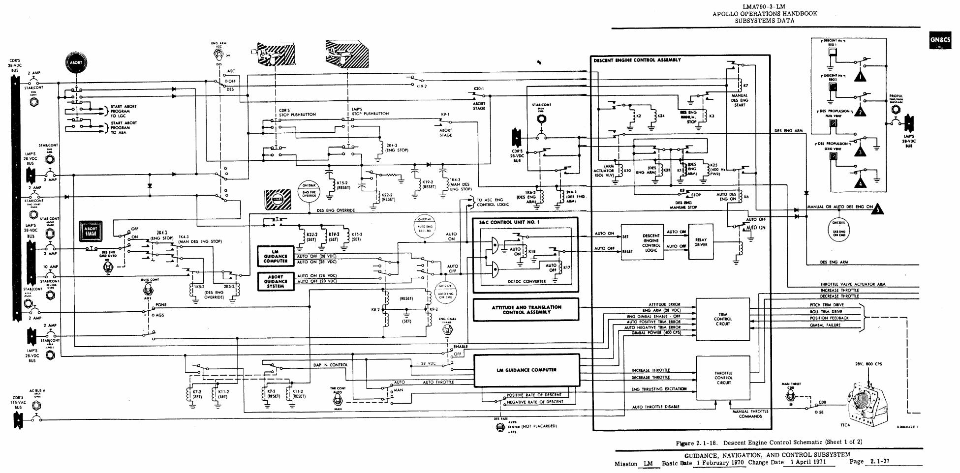
ENG ARM ASC
ON
DES
ASC
0
OFF
I DES
DES ENG STOP)
1775.3
(DES ENG OVERRIDE)
GHI2170
Al110 ENG OFF CIAO
ENG GM11 wuu
4)'•
K20. 1
K9-1
ABORT STAGE
CDR'S 28-VDC
BUS
11(4-3 (MAN DES ENG STOP)
) --••• TO ASC ENG 4.- CONTROL LOGIC
11(6-3 (DES ENG
ARM)
SiaC CONTROL UNIT NO. 1
• ABORT SIAS/CON,' STAGE
att• Iwo
, to• 3 10c3 TN°
0-e- PR OP Ill
ONPMA011
DES ENG ARM
r 085 PROFUSION oxio vINT
r DIESCINT N. RIO I
7.7
r MUM No .1 RIO S
r DES PROPULSION1 A PURE VINT
/1■0111
LAW'S 211-VDC
SUS
10 AMP •
STABICONT AIGNI
IMP'S MAO
18•VoC BUS
OFF
'01'G ON 1/(4.3 3K43
0 (ENG STOP) 0- (MAN
—A I
—. jr—i '0
Lro 2 AMP IN40 0
4
CND DYED 1 A I
rA80; itAGI
DES RATE +IPS
mean (NOT PLACARDED)
1 ENABLE
O OFF
DAP IN CONTROL
4- 28 VDC 0,19
O
LM GUIDANCE COMPUTER
C1
i (SET) : I (S
K7.2 1•1 K11-2
4-1 I
K7.2 K11-2 I ET) I (RESET) (RESET)
t- --,
TI411 CONT
AUTO AUTO THROTTLE
IO MAN
POSITIVE RATE OF DESCENT
NEGATIVE RATE OF DESCENT
STABICONT ONO
IMP'S /UN
28.VDC BUS
0 2 AMP
r*,
CDR'S 115.VAC
BUS
AC BUS A [MCA G/Abl
9 Ate 011121165
ENG FIRE OVERRIDE
DES ENG OVERRIDE
—• •
K 15-2 (SET)
AUTO ON (28 VDC) AUTO OFF (2B VDC)
—Z O
AUTO ON
• AUTO I Kis —3LT
CIO -
AUTO 1: Off ...11 4
DC/DC CONVERTER =
RIP
AUTO OFF 411.
ATTITUDE AND TRANSLATION CONTROL ASSEMBLY
MANUM STOP
SET DESCENT ENGINE
CONTROL
RESET LOGIC
AUTO ON
AUTO OW RELAY
DRIVER
AUTO OFF
— 01—r: I kit°
ON
1111 —
ENG ARM (28 VDC)
ENG GIMBAL ENABLE OFF AUTO POSITIVE TRIM ERROR
AUTO NEGATIVE TRIM ERROR
ATTITUDE ERROR
TRIM CONTROL
CIRCUIT
PITCH TRIM DRIVE
ROLL TRIM DRIVE
POSITION FEEDBACK
GIMBAL FAILURE
THROTTLE CONTROL
CIRCUIT
DECREASE THROTTLE
ENG THRUSTING EXCITATION
AUTO THROTTLE DISABLE
THROTTLE VALVE ACTUATOR ARM
INCREASE THROTTLE
DECREASE THROTTLE
28V, BOO CPS INCREASE THROTTLE
MANUAL THROTTLE COMMANDS
LAW 'S
28-VDC BUS
DXOTIAA-231 I
LMA790 - 3 - LM APOLLO OPERATIONS HANDBOOK
SUBSYSTEMS DATA
I CDR'S I STOP PUSHBUTTON
•
• - ati3C1
(2-0') START ABORT PROGRAM TOLGC
—1:1Ijn_is. STARG
T
r-°
ABORT
) TO AEA PRORAM
2 AMP
e"T'N 0
STABICONT ENG 31101
OvIIG
PIO STABICONT
NS MG
STABICONT c"'" • IT•
2 AMP
2 AMP
LM GUIDANCE COMPUTER
IABORT GUIDANCE
SYSTEM
0 K19.2
I IMP'S STOP PUSHBUTTON
010
21(4-3 (ENG STOP)
• T,
--- I = K19.2 IN 2 (RESET)
riK22-2 (RESET)
K8-2
I K7
K
MANUAL DES ENG
START
K 1(24 NS ENG /1/111111JAL
STOP
T-43
1(25 (400 He PWR)
(ARM ACTUATOR K10 ISOL VLV)
t-f- (DES) ? K23 ENG ARM
(DES
KT ENG ARM)
ofC.2.3.
A.— STOP AUTO ENG
DIG DES
DES 1$ ON 1 .1 K6
lb DESCENT ENGINE CONTROL ASSEMBLY
AUTO ENG
IIII I MI1 AUTO
ON
AUTO OFF
0 1
CDR'S 28.VDC
BUS 2 AMP
/IN
0 ST ABICONT
ONO CONE
OUID CONT
A05
I PGNS
0 AGS
• --0 •-o 0-
MANUAL OR AUTO DES ENG ONA
61113010
MEMO ON ORD
DES ENG ARM
STAB/CONT RNA (NMI
Figure 2. 1-18. Descent Engine Control Schematic (Sheet 1 of 2)
GUIDANCE, NAVIGATION, AND CONTROL SUBSYSTEM Mission LM Basic Date 1 February 1970 Change Date 1 April 1971 Page 2. 1-37
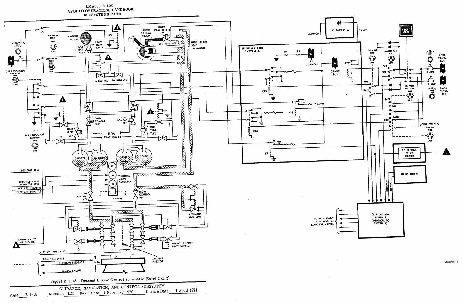
PRPLNT SHUTOFF PILOT VLVS (4)
VARIABLE INJECTOR
INCREASE THROTTLE
O DECREASE THROTTLE r
U
FLOW CONTROL
VLV
FLOW CONTROL VLV
- L _ _
T V V • IV V V
LMA890-3-LM APOLLO OPERATIONS HANDBOOK
SUBSYSTEMS DATA
0 •
NO AMBIENT HELIUM
•■• FROM RELAY BOX B
FUEL/ HELIUM HEAT EXCHANGER
AMB Ho 1$01
VLV
NC
DES PROPULSION FUEL VENT
0 1r
I
He SEC VLV He PRIM VLV
FROM SUPER RELAY BOX g
CRITICAL HELIUM
DESCENT IM REG I
PROPuL
01.4-1\ DESCENT No FEDI
Icool
CLOSE (=>
OXID COMPAT VLV
FUEL COMPAT
VLV
THROTTLE VALVE ACTUATOR :
THROTTLE VALVE ACTUATOR ARM
DES PRuPUISIUN OXID VENT
010
OXID VENT
VLV
FUEL VENT
VI.11 F) 1 FROM --4 RELAY BOX B $---
CEOS(
OXIDIZER I OXIDIZER
44,4# e"' / amma% DES ENG ARM 0
• ■0
S.
■■•=1.,,
K1
I 28-VDC
BUS
ED RELAY BOX SYSTEM A R4 R3
ED COMMON
O •
vvreN...-• 0(S
K14
MASTER ARM
ON r E.-.,
oca CDR'S
28-VDC
-A 1.3 SECOND DELAY
CIRCUIT
ED BATTERY A 28- VDC
DES VENT
FIRE
ril4 • SAFE
OFF SI
FIRE
• SAFE
TS"f43"-: •
SAFE : 4.4 0
FIRE
0
FIREQ-Tr 0
4 0
K13
K15
IC9
COMMON
ED BATTERY •
2 AMP
0 0_
N N. HESS
DISH:TEA"
2 AMP
• Well
SAFE
r DES PRIPLNT.N. ISO( VW
FIRS
SAFE
ABORT ISTAGE
OFF BUS
N O "IN
LMP'S 28•VDC
BUS
ACTUATOR 1501. VLVS
TO REDUNDANT CARTRIDGE IN
EXPLOSIVE VALVES
MANUAL - AUTO DES ENG ON
ED RELAY BOX SYSTEM B
(IDENTICAL TO SYSTEM A)
PITCH TRIM DRIVE
ROLL TRIM DRIVE
POSITION FEEDBACK
GIMBAL FAILURE
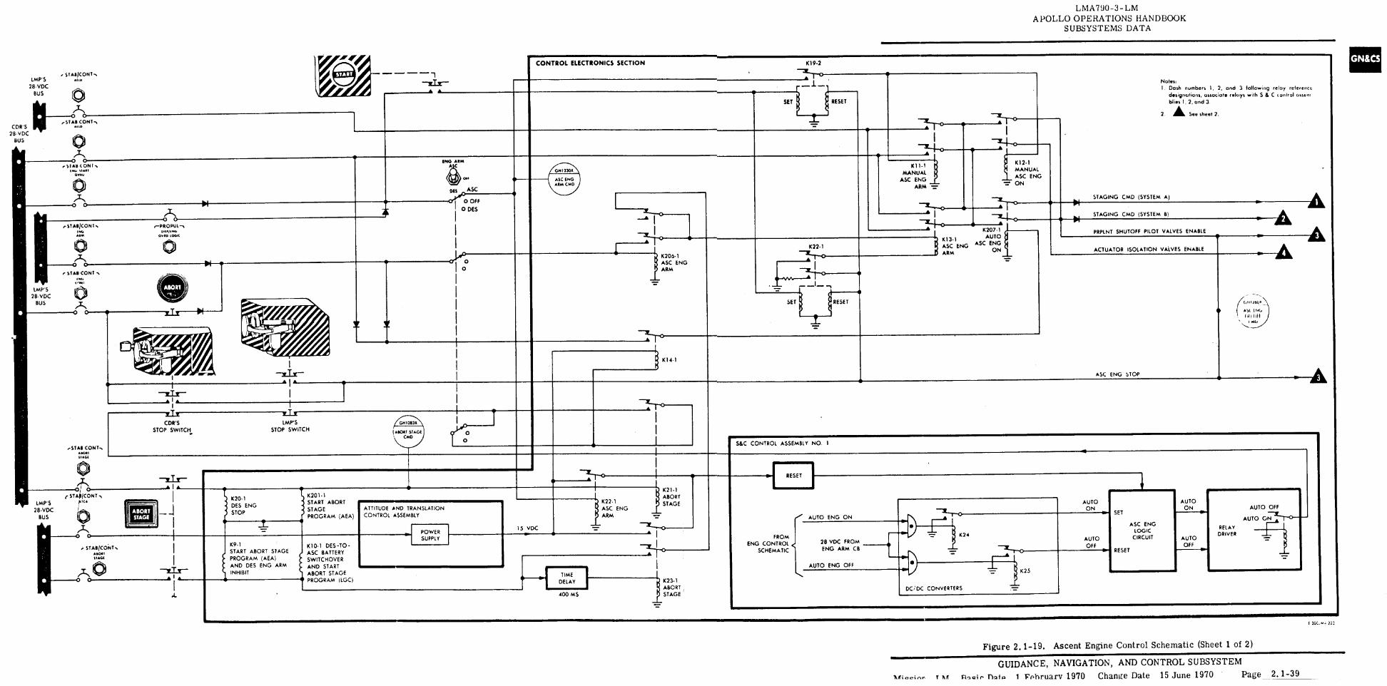
CONTROL ELECTRONICS SECTION 1(19-2
0
GM1213X
(MORT STAGE CMD
&IC CONTROL ASSEMBLY NO.
1 RESET
AUTO ON
RELAY DRIVER
AUTO OFF
AUTO OFF
AUTO CTY" ASC ENG
LOGIC CIRCUIT
STAGING CMD (SYSTEM A)
STAGING CMD (SYSTEM B) A
ST ABICDN1-. IMP'S uu
28-VDC BUS
CDR'S 4rroCONY
OHO ' STAB -,
28-VDC BUS
Notes: I, Dash numbers 1, 2, and 3 following relay reference
designations, associate relays with S 8. C control ossum blies I, 2, and 3.
2. A See sheet 2.
RESET
SET
LMA790-3-LM APOLLO OPERATIONS HANDBOOK
SUBSYSTEMS DATA
START
—7.1x- • •
SET I RESET
AUTO ON
AUTO OFF
0 0 lattONI•
11Allt
OW. * 'MAO/CONT.
61111M
0 0
sTAIPCONT
(OM
IMP'S 21I•VDC
BUS
0 0 c-PROPLII.
D11./10.
04.D LOGIC
• l•
• •
ZIS CDR'S Imes
STOP SWITCH STOP SWITCH
• 1 • O
CONT.. AAO*1
1114C.F
0 ST APICONT
uA
ABORT STAGE
IMP'S 28-VDC
BUS
STABIC6NT, .011 SIAGI
K20-1 DESD ENG
STOP
K9.1 START ABORT STAGE PROGRAM (AEA) AND DES ENG ARM INHIBIT
K201.1 START ABORT STAGE PROGRAM (AEA)
K10.1 DES -TO - ASC BATTERY SWITCHOVER AND START ABORT STAGE PROGRAM (LGC)
PRPINT SHUTOFF PILOT VALVES ENABLE
ACTUATOR ISOLATION VALVES ENABLE
(a. 6111100. 1 _
ASC ENG STOP
A St lt+e, NI lit
I MU N.„
K14.1
DES
oN ASC
0 OFF
GM I 2300
ASC ENG AIM CMD
SET
-s
RESET
• 1(12-1 MANUAL ASC ENG
Tr ON
K1, t MANUAL
ASC ENG ARM
K207 1
K13-1 AUTO ASC ENG ASC ENG ARM ON
Tr
K22.1 —7
•
I
1(206.1 ASC ENG ARM
0 DES
II
O O
ING ARM A C
ATTITUDE AND TRANSLATION CONTROL ASSEMBLY
POWER SUPPLY
1 K22.1 ASC ENG ARM
01-1 ABORT STAGE
—X-- 0
K23.1 ABORT
-L- e STAGE
-LT
AUTO ENG ON
AUTO ENG OFF
DC/ DC CONVERTERS
15 VDC
28 VDC FROM ENG ARM CB
K24
K25
FROM ENG CONTROL
SCHEMATIC
TIME DELAY
400 MS
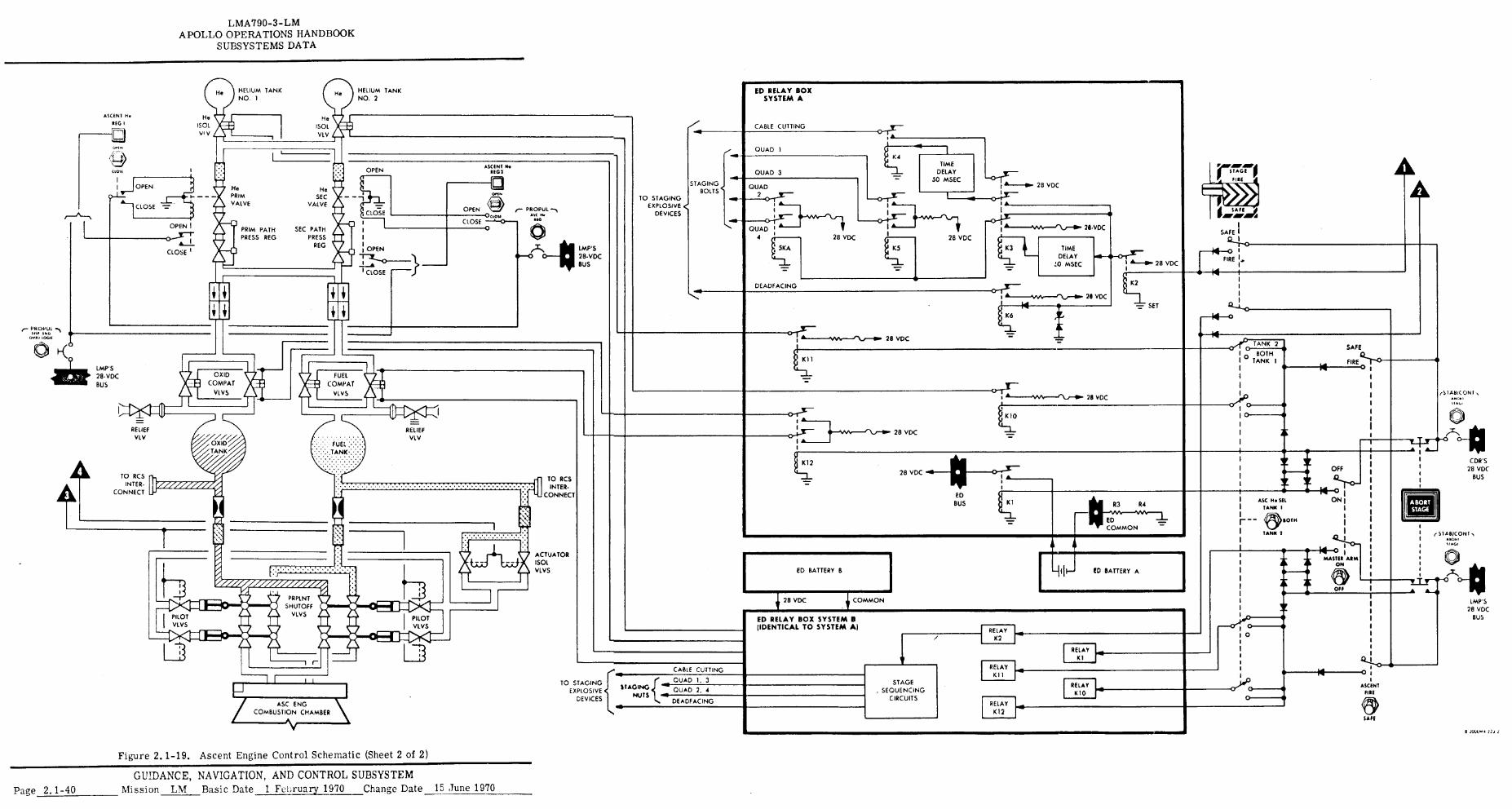
HELIUM TANK NO. 1
411 HELIUM TANK NO. 2
He 1501 VLV
He ISO( VI V
• ter
417"
OPEN
He SEC
VALVE
ASCENT H• REG I
Lcij
Or.
viOPEN
CLOSE
STAGING BOLTS
TO STAGING EXPLOSIVE <
DEVICES
IMP'S 28-VDC BUS
I ■ V A
SEC A PRIM PATH 4 ,i,
PRESS REG PRESS REG V
t I I ij i • I OPEN
.411- 1-3E- 1
110 DO BO
I A--0. 28 VDC FIRE
1
K2
SET
4
TANK 2 0 SAFE
I BOTH I - TANK I FIRE Q.7 -43
• w 0 IMP'S 28. V DC BUS
FUEL COMPAT
VLVS
v_. "'
► 1■ 11
VAin: COMPAT OXID
vtvs "
RELIEF VLV
OXID FUEL :• TANK
•
RELIE
-
F VLV
TO RCS INTER.
CONNECT
TO RCS INTER.
CONNECT
• • • • ACTUATOR 1501 VLVS
I11 TO STAGING
EXPLOSIVE DEVICES
.(e QUAD 1. 3 S AGING
NUTS QUAD 2. 4
DEADFACING ASC ENG COMBUSTION CHAMBER
I -9 CABLE CUTTING
(SIABIC ON I
0
O
0
ASC NT II I
SASS
0
AI
CDR'S 28 VDC
BUS
ABORT STAGE
(STAINCONT 11.1
IMP'S 28 VDC
BUS
O
4C
OFF
14 0 ON1
1 1
14 0 1 MASTER ARM
ON
• OFF
• I
ASC 11• SS TANK I
4-4 • BOTH
TANK 2
LMA790-3-LM APOLLO OPERATIONS HANDBOOK
SUBSYSTEMS DATA
28 VDC
QUAD 1
QUAD 3
QUAD
•
QUAD 1 4
5KA
....vv.„...„\al
I• 1
28 VDC
KS
A—••■• 28 VDC
• A—NA0V—r\a-11A 28 , VDC
TIME DELAY
50 MSEC
ED RELAY BOX SYSTEM A
CABLE CUTTING
K L
ED BUS
ED RELAY BOX SYSTEM B (IDENTICAL TO SYSTEM A) RELAY
K2
RELAY
V K1
RELAY KI1
STAGE RELAY , SEQUENCING K10
CIRCUITS RELAY .01
K12
R3 R4
ED COMMON
ED BATTERY A
DEADFACING
a-0. 28 VDC
Kll
I • 0-5An..--11.../-11. 28 VDC
1 •
K12
28 VDC
ED BATTERY B
28 VDC 1 COMMON
OTT-
28 VDC I 144
K6
28 VDC
K10
1 A--
K1
Figure 2.1-19. Ascent Engine Control Schematic (Sheet 2 of 2)
GUIDANCE, NAVIGATION, AND CONTROL SUBSYSTEM Page 2.1-40 Mission LM Basic Date 1 Fei,ruary 1970 Change Date 15 June 1970
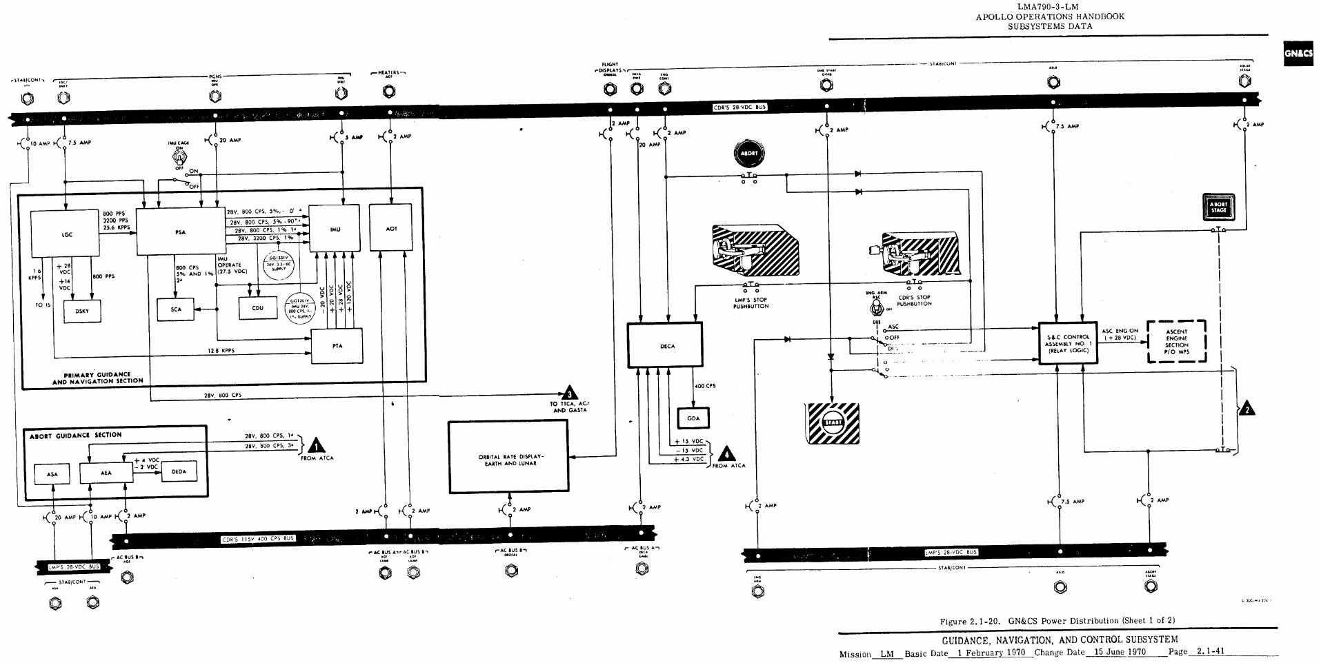
FLIGHT eDISPLAYS-Er
01101 ■1 PIC• • or IMO
CDR'S 28-VDC BUS
28V, BOO CPS, 5% • VC.
PSA LOC ♦11►
800 PPS 3200 PPS 25.6 KPPS 11.•
28V, BOO CPS, 5%, • 0' . Rr
28V, 800 CPS, 1% 1. 28V, 3200 CPS, 1%
28V, 800 CPS
• ABORT GUIDANCE SECTION
+ 4 VDC - 2 VDC
28V 800 CPS, 1. }
28V, 800 CPS, 3•
FROM ATCA
ASA
AEA
DEDA
2 MO l< l< 0
2 AMP 0
2 AMP 0 r O
r\ 07.5 AMP M
O 2 AMP
LMA790-3-LM APOLLO OPERATIONS HANDBOOK
SUBSYSTEMS DATA
SI AtliCONI INO 11 AM A.10
WISP • 11.11 11641
r ST•IICONT / PGNS
NMI
op. INr
CONI
0 0
• 1< 7.5 AMP 34. 5 AMA 2 AMP
0 0 K 2 AMP r-( 010 AMP l< 7.5 AMP 0 IMU CAGE
ON I"( 20 AMP 1‹ 2 AMP
0 Q 20 AMP
o2 AMP
F 0
ON
OFF
IMU
AOT
ABORT SIAM
A
CDU ING AIM
AC
+ 28 VDC +14 BOO PPS
VDC
DSKY
BOO CPS 5% AND I %
SCA
IMU OPERATE (27.5 VDC)
GGiniv
200. 3 3. KC SUPPLY
0 0
IMP'S STOP PUSHBUTTON
ILLIa 0 0
CDR'S STOP PUSHBUTTON
1.6 KPPS
TO IS
PTA ASC ENG•ON ( + 28 VDC)
r Mena MEM., di
ASCENT
SECTION I ENGINE
P/0 MPS
L 4r•o■ ._J
S & C CONTROL ASSEMBLY NO. 1
(RELAY LOG C)
12 . B KPPS
PRIMARY GUIDANCE AND NAVIGATION SECTION
400 CPS
TO ITCA, AND GASTA
+ 4.3 VDC
+ 15 VDC
- 15 VDC ORBITAL RATE DISPLAY-
EARTH AND LUNAR }FROM ATCA
•
1 1 I-C20 AMP K 10 AMP K 2 AMP•
o 9
r• AC BUS II '1 • GS
LNAP'S 28-VDC BUS
CDR'S 115V 400 CPS BUS
2 AMP K 2 AMP
r- AC BUS An PICA
thAP'S 28-VDC BUS
e• AC BUS Ai r AC BUS
rAC BUS Bn • 0. •01
oacx•L 1•1■11 LAMP
STABICONT • 1A
ADC ST ANCONT
• I•
ARD • 11,0111 11•Gf
0 u )0.,M. 1:0. I
Figure 2.1-20. GN&CS Power Distribution (Sheet 1 of 2)
GUIDANCE, NAVIGATION, AND CONTROL SUBSYSTEM Mission LM Basic Date 1 February 1970 Change Date 15 June 1970 Page 2.1-41
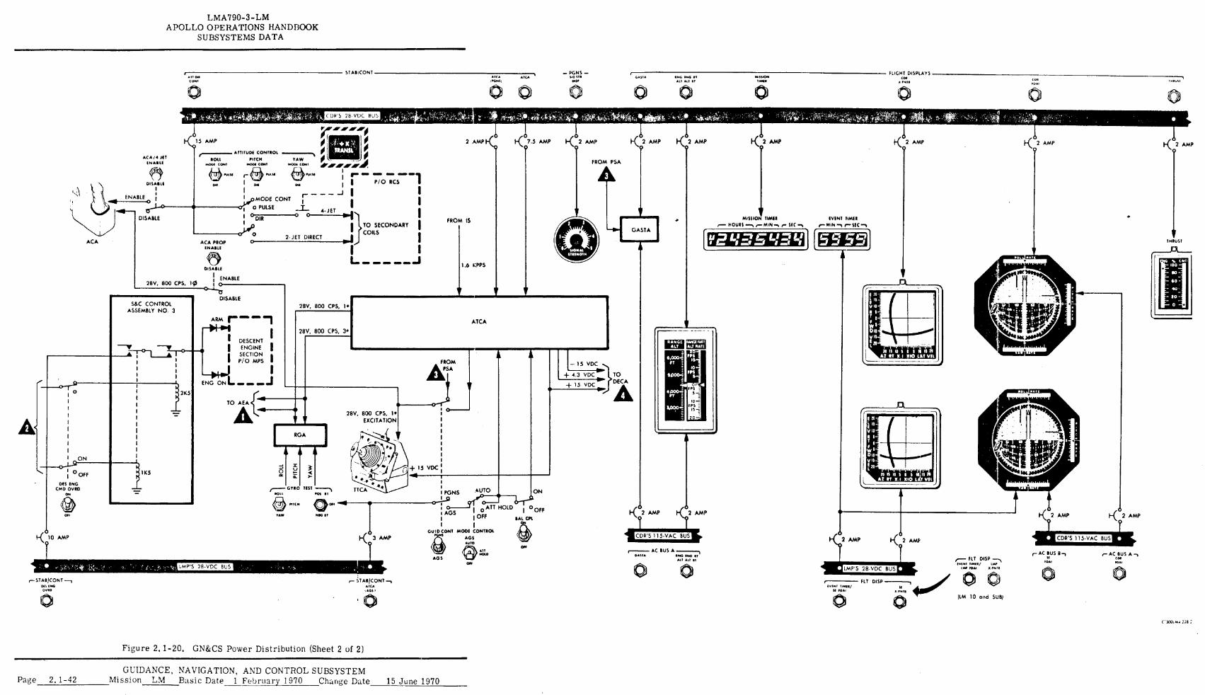
ACA /A JET SNARLS
IT\ ,
ACA PROP ENABLE
28V, 800 CPS, 10
DISABLE
I ENABLE O
FROM PSA
EVENT TIMER
THRUST
RMIGEROF ALT RATE
RGA
LMA790-3-LM APOLLO OPERATIONS HANDBOOK
SUBSYSTEMS DATA
STABICONT Mr, 00 COM!
• tr•
•1CA MGHSJ
DISABLE
ENABLE 0 j
ACA
S&C CONTROL ASSEMBLY NO. 3
II2i/APAFAR/10
15 AMP ; ' . 0 -4x . / / IMM ,■............ ATTITUDE CONTROL A..■Am.,,
ROIL PITCH YAW 0 L
A001 ----',/
l .M IP' 41•41/ IP APi. 0COM
MAU r- 0
001 COAT 0001
"'" M ..fCO %MN
I
1 r --,701-cr -1 I . 1 i„. . 1
1 I - MODE CONT
r 1 I I
1 0 PULSE
I ° DIR I
0
0 2- JET DIRECT
z71- 4 0______44- JET )
mj COILS
I TO SECONDARY
I
I
I
DISABLE
28V, 800 CPS, 1•
FROM IS MISSION SIMI
1.6 KPPS
GASTA ff=1„1:1CLI',01
a"
PGNS — FLIGHT DISPLAYS HG .11
GAM
1140 1040 II
0410014 COM 04$0
•
Alf 01
11•0,10 it Mill
28V, 800 CPS, 3•
__A-0i • I
.12K5
ARM r" -1 -M-01
I I DESCENT
I ENGINE I
I SECTION P/0 MPS I
04 1.11 ENG ON OM MO OM
TO AEA[ A
28V, 800 CPS, I. EXCITATION
ATCA
FROM
ASA +4.3
- 15 VDC
VDC 110.
15 VDC 1111.
TO DECA
+I5 VDC
.41 11K5
TTCA wll AUTO ON POI 0l PGNS
GYRO TEST
O.*" ° MEG 0, FAGS
?fe.°0
I o ATT HOLD DOFF
OFF IIAL CPS I I
, K 3 AMP
GUIDCONT MOD::ONTROL 10 AGE
i< 2 AMP .c0T2 AMP
'CDR'S 115-VAC BUS gr
4.1.0 NICM
TAO
o
1 ON
I 0 OFF
DES ENG CMD OVRO
oft
00
OTT
* ON
All
AGS GAOL
AC BUS A ONG LNG IT AO MI II
,—STAB/CONT.--, TABICONT NS MG
MCA 0.0
t•G$ I
FIT DISP v■ Fmr 11011.11/
LI NMI * C . 300 ,1 278 :
Figure 2.1-20. GN&CS Power Distribution (Sheet 2 of 2)
GUIDANCE, NAVIGATION, AND CONTROL SUBSYSTEM Page 2.1-42 Mission LM Basic Date 1 February 1970 Change Date 15 June 1970
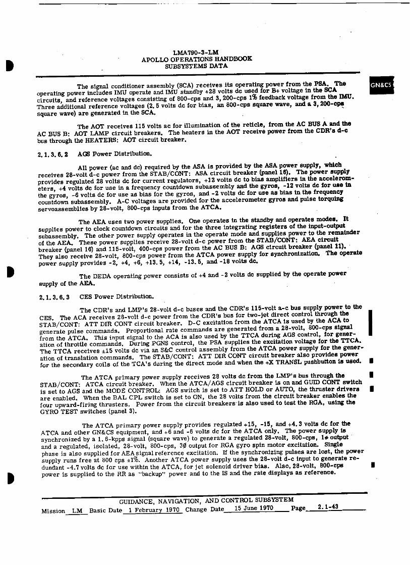
11 LMA790-3-LM
APOLLO OPERATIONS HANDBOOK SUBSYSTEMS DATA
The signal conditioner assembly (SCA) receives its operating power from the PSA. The operating power includes IMU operate and IMU standby +28 volts dc used for B+ voltage in the SCA circuits, and reference voltages consisting of 800-cps and 3, 200-cps 1% feedback voltage from the IMU. Three additional reference voltages (2. 5 volts dc for bias, an 800-cps square wave, and a 3, 200-cps square wave) are generated in the SCA.
The AOT receives 115 volts ac for illumination of the reticle, from the AC BUS A and the AC BUS B: AOT LAMP circuit breakers. The heaters in the AOT receive power from the CDR's d-c bus through the HEATERS: AOT circuit breaker.
2.1. 3. 6. 2 AGS Power Distribution.
All power (ac and dc) required by the ASA is provided by the ASA power supply, which receives 28-volt d-c power from the STAB/CONT: ASA circuit breaker (panel 16). The power supply provides regulated 28 volts dc for current regulators, +12 volts dc to bias amplifiers in the accelerom-eters, +4 volts de for use in a frequency countdown subassembly and the gyros, -12 volts de for use in the gyros, -6 volts dc for use as bias for the gyros, and -2 volts de for use as bias in the frequency countdown subassembly. A-C voltages are provided for the accelerometer gyros and pulse torquing servoassemblies by 28-volt, 800-cps inputs from the ATCA.
The AEA uses two power supplies. One operates in the standby and operates modes. It supplies power to clock countdown circuits and for the three integrating registers of the input-output subassembly. The other power supply operates in the operate mode and supplies power to the remainder of the AEA. These power supplies receive 28-volt d-c power from the STAB/CONT: AEA circuit breaker (panel 16) and 115-volt, 400-cps power from the AC BUS B: AGS circuit breaker (panel 11). They also receive 28-volt, 800-cps power from the ATCA power supply for synchronization. The operate power supply provides -2, +4, +6, +13. 5, +14, -13. 5, and -18 volts dc.
The DEDA operating power consists of +4 and -2 volts de supplied by the operate power supply of the AEA.
2. 1. 3. 6. 3 CES Power Distribution.
The CDR's and LMP's 28-volt d-c buses and the CDR's 115-volt a-c bus supply power to the CES. The ACA receives 28-volt d-c power from the CDR's bus for two-jet direct control through the STAB/CONT: ATT DIR CONT circuit breaker. D-C excitation from the ATCA is used by the ACA to generate pulse commands. Proportional rate commands are generated from a 28-volt, 800-cps signal from the ATCA. This input signal to the ACA is also used by the TTCA during AGS control, for gener-ation of throttle commands. During PGNS control, the PSA supplies the excitation voltage for the TTCA. The TTCA receives ±15 volts de via an S&C control assembly from the ATCA power supply for the gener-ation of translation commands. The STAB/CONT: ATT DIR CONT circuit breaker also provides power for the secondary coils of the TCA's during the direct mode and when the +X TRANSL pushbutton is used. ■
The ATCA primary power supply receives 28 volts de from the LMP's bus through the STAB/CONT: ATCA circuit breaker. When the ATCA/AGS circuit breaker is on and GUID CONT switch is set to AGS and the MODE CONTROL: AGS switch is set to ATT HOLD or AUTO, the thruster drivers II are enabled. When the BAL CPL switch is set to ON, the 28 volts from the circuit breaker enables the four upward-firing thrusters. Power from the circuit breakers•is also used to test the RGA, using the GYRO TEST switches (panel 3).
The ATCA primary power supply provides regulated +15, -15, and +4. 3 volts dc for the ATCA and other GN&CS equipment, and +6 and -6 volts dc for the ATCA only. The power supply is synchronized by a 1, 6-kpps signal (square wave) to generate a regulated 28-volt, 800-cps, 10 output and a regulated, isolated, 28-volt, 800-cps, 30 output for RGA gyro spin motor excitation. Single phase is also supplied for AEA signal reference excitation. If the synchronizing pulses are lost, the power supply runs free at 800 cps ±i%. Another ATCA power supply uses the 28-volt d-c input to generate re-dundant -4.7 volts dc for use within the ATCA, for jet solenoid driver bias. Also, 28-volt, 800-cps power is supplied to the RR as "backup" power and to the IS and the rate displays as reference.
■
GUIDANCE, NAVIGATION, AND CONTROL SUBSYSTEM Mission LM Basic Date 1 February 1970 Change Date 15 June 1970 Page 2. 1-43
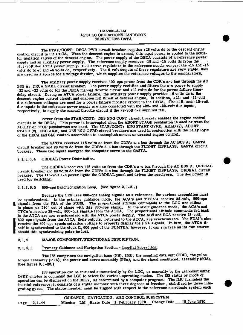
LMA790-3-LM APOLLO OPERATIONS HANDBOOK
SUBSYSTEMS DATA
The STAB/CONT: DECA PWR circuit breaker supplies +28 volts dc to the descent engine control circuit in the DECA. When the descent engine is armed, this input power is routed to the actua-tor isolation valves of the descent engine. The power supply of the DECA consists of a reference power supply and an auxiliary power supply. The reference supply receives +15 and -15 volts dc from the ±-4.3-volt d-c ATCA power supply. D-C active regulators in the reference supply convert the +15 and -15 volts de to +6 and -6 volts dc, respectively. The 6-volt outputs of these regulators are very stable; they are used as a source for a voltage divider, which supplies the reference voltages to the comparators.
The auxiliary power supply receives 400-cps power from the CDR's a-c bus through the AC BUS A: DECA GMBL . circuit breaker. The power supply rectifies and filters the a-c power to supply +22 and -22 volts dc for the DECA manual throttle circuit and +22 volts dc for the power failure time-delay circuit. During an ATCA power failure, the auxiliary power supply provides +6 volts dc to the descent engine control circuit and enables full thrust of descent engine. In addition, +22- and -22-volt d-c reference voltages are used for a power failure monitor circuit in the DECA. The +15- and -15-volt d-c inputs to the reference power supply are also connected with the +22- and -22-volt d-c inputs, respectively, to supply the manual throttle circuit if the 22-volt d-c supplies fail.
Power from the STAB/CONT: DES ENG CONT circuit breaker enables the engine control circuits in the DECA. This power is interrupted when the ABORT STAGE pushbutton is used or when the ABORT or STOP pushbuttons are used. The STAB/CONT: ENG START OVRD, AELD (2), ABORT STAGE (2), ENG ARM, and DES ENG OVRD circuit breakers are used in conjunction with the relay logic of the DECA and S&C control assemblies to accomplish ascent or descent engine control.
The GASTA receives 115 volts ac from the CDR's a-c bus through the AC BUS A: GASTA circuit breaker and 28 volts dc from the CDR's d-c bus through the FLIGHT DISPLAYS: GASTA circuit breaker. These two inputs energize the computer servo in the GASTA.
2.1.3.6.4 ORDEAL Power Distribution.
The ORDEAL receives 115 volts ac from the CDR's a-c bus through the AC BUS B: ORDEAL circuit breaker and 28 volts de from the CDR's d-c bus through the FLIGHT DISPLAYS: ORDEAL circuit breaker. The 115-volt a-c power lights the ORDEAL panel and drives the resolvers. The d-c power is used for switching.
2.1.3.6.5 800-cps Synchronization Loop. (See figure 2.1-21.)
Because the CES uses 800-cps analog signals as a reference, the various assemblies must be synchronized. In the primary guidance mode, the ACA's and TTCA ' s receive 28-volt, 800-cps signals from the PSA of the PGNS. The proportional attitude commands to the LGC are either in phase or 180° out of phase with this 800-cps signal. In the abort guidance mode, the ACA's and TTCA ' s receive 28-volt, 800-cps signals from the ATCA. The proportional attitude commands fed back to the ATCA are now synchronized with the ATCA power supply. The AGS and RGA receive 28-volt, 800-cps signals from the ATCA; their outputs, returned to the ATCA, are synchronized. The FDAI's also receive the 800-cps synchronization voltage to properly display the RGA signals. In turn, the ATCA it-self is synchronized to the clock (1, 600 pps) of the PCMTEA; however, it can run free as its own source should this synchronizing pulse be lost.
2.1.4 MAJOR COMPONENT/FUNCTIONAL DESCRIPTION.
2.1.4.1 Primary Guidance and Navigation Section - Inertial Subsection.
The ISS comprises the navigation base (NB), IMU, the coupling data unit (CDU), the pulse torque assembly (PTA), the power and servo assembly (PSA), and the signal conditioner assembly (SCA). (See figure 2.1-22.)
MS operation can be initiated automatically by the LGC, or manually by the astronaut using DSKY entries to command the LGC to select the various operating modes. The ISS status or mode of operation can be displayed on the DSKY, as determined by a computer program. The IMU furnishes the inertial reference; it consists of a stable member with three degrees of freedom, stabilized by three inte-grating gyros. The stable member must be aligned with respect to the reference coordinate system each
GUIDANCE, NAVIGATION, AND CONTROL SUBSYSTEM Page 2.1-44 Mission LM Basic Date 1 February 1970 Change Date 15 June 1970
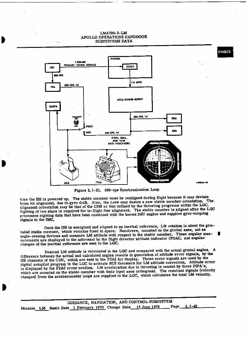
PCMTEA 1.024-MC
PRIMARY TIMING SIGNALS CLOCK
KG PPS
800 CPS, 10 1.6 KPPS
ATCA POWER SUPPLY
800 CPS, 10
800 CPS, 10
PITCH, ROLL, AND YAW
RATE INDICATORS
GUIOCOMI
ws^ PGNS
AGS AEA
p
4300lA4130
Figure 2.1-21. 800-cps Synchronization Loop
LMA 790-3- LM APOLLO OPERATIONS HANDBOOK
SUBSYSTEMS DATA
time the ISS is powered up. The stable member must be realigned during flight because it may deviate from its alignment, due to gyro drift. Also, the crew may desire a new stable member orientation. The alignment orientation may be that of the CSM or that defined by the thrusting programs within the LGC. Sighting of two stars is required for in-flight fine alignment. The stable member is aligned after the LGC processes sighting data that have been combined with the known IMU angles and supplies gyro-torquing signals to the IMU.
Once the ISS is energized and aligned to an inertial reference, LM rotation is about the gim-baled stable member, which remains fixed in space. Resolvers, mounted on the gimbal axes, act as angle-sensing devices and measure LM attitude with respect to the stable member. These angular mea-surements are displayed to the astronaut by the flight director attitude indicator (FDAI), and angular changes of the inertial reference are sent to the LGC.
Desired LM attitude is calculated in the LGC and compared with the actual gimbal angles. A difference between the actual and calculated angles results in generation of attitude error signals, by the ISS channels of the CDU, which are sent to the FDAI for display. These error signals are used by the digital autopilot program in the LGC to activate RCS thrusters for LM attitude correction. Attitude error is displayed by the FDAI error needles. LM acceleration due to thrusting is sensed by three PIPA's, which are mounted on the stable member with their input axes orthogonal. The resultant signals (velocity changes) from the accelerometer loops are supplied to the LGC, which calculates the total LM velocity.
GUIDANCE, NAVIGATION, AND CONTROL SUBSYSTEM Mission LM Basic Date 1 February 1970 Change Date 15 June 1970 Page 2.1-45

LMA790-3- LM APOLLO OPERATIONS HANDBOOK
SUBSYSTEMS DATA
AGS 28V 800-CPS RFERENCE
PONS
GUID COW
FROM RGA
RATE ERRORS MALFUNCTION
DETECTION (LGC-CONTROLLED)
TEMPERATURE CONTROL (IMU/PSA)
PIPA PULSES
ACCELEROMETER LOOPS (PTA)
ACCELEROMETER 1 t ACCELEROMETER TORQUING SIGNALS OUTPUTS
IMU
TOTAL ATTITUDE
ATTITUDE ERRORS
FORWARD LATERAL VELOCITY VELOCITY VELOCITY
CHANGE CALCULATION
PULSES11. TO LOC
GIMBAL ANGLES
COARSE vni ALIGNMENT
ERROR
GYRO t GIMBAL DRIVE
OUTPUTS SIGNALS
STABILIZATION LOOPS
(UAW PSA)
FORWARD AND LATERAL
VELOCITY
DIGITAL COMMANDS AND DATA FLOW
MALFUNCTION DETECTION
TORQUE ENABLE
COMMANDS GYRO TORQUE ELECTRONICS
(PTA)
•
LC GYRO TORQUE SIGNALS
c.xcum.Ist
I ATCA I EPS.'
TORQUE
Figure 2.1-22. Inertial Subsection - Functional Diagram
2.1.4.1.1 Navigation Base. (See figure 2.1-23.)
The navigation base is a lightweight mount that supports, in critical alignment, the IMU, ASA, and AOT. It consists of a center ring with four legs that extend from either side. The IMU is mounted to the ends of one side of the four legs. The AOT and the ASA are mounted to the opposite ends of the legs. The navigation base is bolted to the LM structure above the astronauts' head, with three mounting pads on the center ring. An electrical grounding strap is attached to the center ring and to the LM structure.
2.1.4.1.2 Inertial Measurement Unit. (See figure 2.1-24. )
The IMU uses three Apollo 25-inertial reference integrating gyros (IRIG's) to sense changes in stable member orientation, and three 16-pulse integrating pendulous accelerometers (PIPA's) to sense velocity changes. The 25-IRIG's are fluid- and magnetically-suspended, single-degree-of-freedom gyros with a 2.5-inch-diameter case. The 16-PIPA's are fluid- and magnetically-suspended, pendulum-type devices with a 1.6-inch-diameter case. The IMU gimbals consist of an outer gimbal mounted to the case, a middle gimbal mounted to the outer gimbal, and an inner gimbal (stable member) mounted to the
GUIDANCE, NAVIGATION, AND CONTROL SUBSYSTEM Page 2.1-46 Mission LM Basic Date 1 February 1970 Change Date
•
COUPLING DATA UNIT
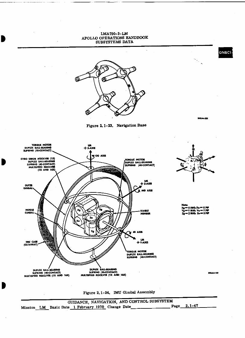
TORQUE MOTOR DUPLEX BALL-BEARING
SUPRING (50-CONTACT)
00 AXIS GYRO ERROR RESOLVE* (IX)
DUPLEX BALL-BEARING SUPRING (40-CONTACT)
MULTISPEED RESOLVER (1X AND I6X)
1M + )(AXIS
TORQUE MOTOR DUPLEX BALL-BEARING SLIMING Oa-CONTACT)
LM OUTER + Z-AXIS
GIMBAL
MG AXIS
Nobs X1 X WIG; Us. X PIP
STABLE Yr■ Y IMO; Ya ■• Y MP MEMBER Z.—ZIRIG, Zama PIP
IG AXIS
MIDDLE GIMBAL
IMU CASE -' (CUTAWAY)
LM + Y-AXIS
TORQUE MOTOR DUPLEX BALL-BEARING SUPRING (40 CONTACT)
DUPLEX BALL-BEARING SUPRING (40-CONTACT)
MULTISPEED RESOLVER (1X AND 16X)
DUPLEX BALL-BEARING SUPRING (50-CONTACT)
MULTISPEED RESOLVER (1X AND 161Q 3001M4•1112
LMA790-3- LM APOLLO OPERATIONS HANDBOOK
SUBSYSTEMS DATA
Figure 2.1-23. Navigation Base
3001M4403
Figure 2.1-24, IMU Gimbal Assembly
GUIDANCE, NAVIGATION, AND CONTROL SUBSYSTEM Mission LM Basic Date 1 February 1970 Change Date Page 2.1-47
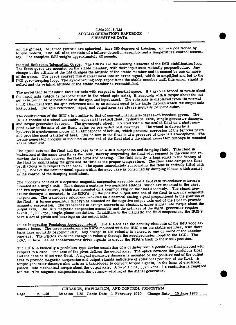
LMA790-3-LM APOLLO OPERATIONS HANDBOOK
SUBSYSTEMS DATA
middle gimbal. All three gimbals are spherical, have 360 degrees of freedom, and are positioned by torque motors. The IMU also consists of a failure-detection assembly and a temperature control assem-bly. The complete IMU weighs approximately 42 pounds.
Inertial Reference Integrating Gyros. The IRIG's are the sensing elements of the IMU stabilization loop. The three gyros are mounted on the stable member, with their input axes mutually perpendicular. Any change in the attitude of the LM changes the attitude of the stable member and is sensed by one or more of the gyros. The gyros convert this displacement into an error signal, which is amplified and fed to the IMU gyro-torquing loop. The gyro-torquing loop repositions the stable member until this error signal is nulled and the original attitude of the stable member is reestablished.
The gyros tend to maintain their attitude with respect to inertial space. If a gyro is forced to rotate about I the input axis (which is perpendicular to the wheel spin axis), it responds with a torque about the out-
put axis (which is perpendicular to the spin and input axes). The spin axis is displaced from its normal (null) alignment with the spin reference axis by an amount equal to the angle through which the output axis has rotated. The spin reference, input, and output axes are always mutually perpendicular.
The construction of the IRIG's is similar to that of conventional single-degree-of-freedom gyros. The IRIG's consist of a wheel assembly, spherical (sealed) float, cylindrical case, single generator ducosyn,
I and torque generator ducosyn. The gyroscopic wheel, mounted within the sealed float on a shaft per-pendicular to the axis of the float, spins on preloaded ball bearings. The wheel is driven by a hysteresiS •synchronous motor in an atmosphere of helium, which prevents corrosion of the ferrous parts and provides good transfer of heat. The helium in the float IS at'a pressure of one-half atmosphere. The torque generator ducosyn is mounted on one end of the float shaft; the signal generator ducosyn is mounted at the other end.
The space between the float and the case is filled with a suspension and damping fluid. This fluid is maintained at the same density as the float, thereby suspending the float with respect to the case and re-moving the friction between the float pivot and bearing. The fluid density is kept equal to the density of the float by maintaining the gyro and its fluid at the proper temperatures. The..fluid also damps the float 'oscillations with respect to the case. The space immediately surrounding the float is entirely filled with fluid. Most of the nonfunctional space within the gyro case is consumed by damping blocks which assist in the control of the damping coefficient.
The ducosyns consist of a separate magnetic suspension assembly and a separate transducer microsyn mounted as a single unit. Each ducosyn contains two separate stators, which are mounted to the case, and two separate rotors, which are mounted on a common ring on the float assembly. The signal gen-erator ducosyn is mounted, in the IRIG's, on the positive output-axis end of the float to provide magnetic suspension. The transducer microsyn provides an electrical analog signal proportional to the position of the float. A torque generator ducosyn is mounted on the negative output-axis end of the float to provide magnetic suspension. The transducer microsyn converts an electrical error signal into torque about the output axis. The IRIG magnetic suspension assembly and the primary of the signal generator require 4-volt, 3,200-cps, single-phase excitation. In addition to the magnetic and fluid suspension, the IRIG's have a set of pivots and bearings on the output axis.
Pulse Integrating Pendulous Accelerometers. The PIPA's are the sensing elements of the IMU acceler-ometer loops. The three accelerometers are mounted with the IRIG's on the stable member, with their input axes mutually perpendicular. Any change in LM velocity is sensed by one or more of the acceler-ometers. The PIPA's route the change in velocity through the accelerometer loops to the LGC. The LGC, in turn, issues accelerometer drive signals to torque the PIPA's back to their null position.
The PIPA is basically a pendulum-type device consisting of a cylinder with a pendulous float pivoted with respect to a case. The axis of the pivot defines the output axis. The space between the pendulous float and the case is filled with fluid. A signal generator ducosyn is mounted on the positive end of the output axis to provide magnetic suspension and output signals indicative of rotational position of the float. A torque generator ducosyn also acts as a transducer to convert torque signals, in the form of electrical pulses, into mechanical torque about the output axis. A 2-volt rms, 3, 200-cps, 14 excitation is required for the PIPA magnetic suspension and the primary winding of the signal generator.
•
•
• GUIDANCE, NAVIGATION, AND CONTROL SUBSYSTEM
Page 2.1-48 Mission LM Basic Date 1 February 1970 Change Date 15 June 1970
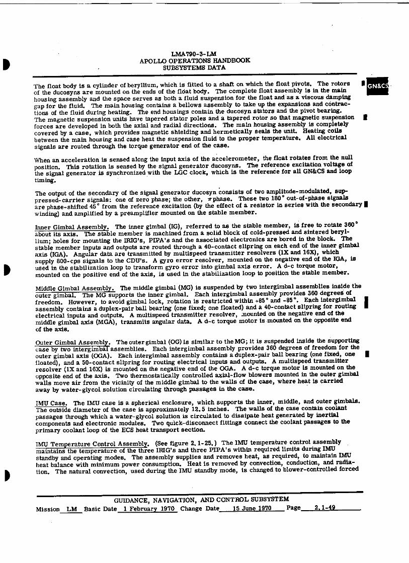
LMA 790-3- LM APOLLO OPERATIONS HANDBOOK
SUBSYSTEMS DATA
The float body is a cylinder of beryllium, which is fitted to a shaft on which the float pivots. The rotors 11:: of the ducosyns are mounted on the ends of the float body. The complete float assembly is in the main housing assembly and the space serves as both a fluid suspension for the float and as a viscous damping gap for the fluid. The main housing contains a bellows assembly to take up the expansions and contrac-tions of the fluid during heating. The end housings contain the ducosyn stators and the pivot bearing. The magnetic suspension units have tapered stator poles and a tapered rotor so that magnetic suspension 11 forces are developed in both the axial and radial directions. The main housing assembly is completely covered by a case, which provides magnetic shielding and hermetically seals the unit. Heating coils between the main housing and case heat the suspension fluid to the proper temperature. AU electrical signals are routed through the torque generator end of the case.
When an acceleration is sensed along the input axis of the accelerometer, the float rotates from the null position. This rotation is sensed by the signal generator ducosyns. The reference excitation voltage of the signal generator is synchronized with the LGC clock, which is the reference for all GN&CS and loop timing.
The output of the secondary of the signal generator ducosyn consists of two amplitude-modulated, sup-pressed-carrier signals: one of zero phase; the other, r phase. These two 180 ° out-of-phase signals are phase-shifted 45 ° from the reference excitation (by the effect of a resistor in series with the secondary I winding) and amplified by a preamplifier mounted on the stable member.
Inner Gimbal Assembly. The inner gimbal (IG), referred to as the stable member, is free to rotate 360 ° about its axis. The stable member is machined from a solid block of cold-pressed and sintered beryl-
lium; holes for mounting the IRIG's, PIPA's and the associated electronics are bored in the block. The stable member inputs and outputs are routed through a 40-contact slipring on each end of the inner gimbal axis (IGA). Angular data are transmitted by multispeed transmitter resolvers (1X and 16X), which supply 800-cps signals to the Call's. A gyro error resolver, mounted on the negative end of the IGA, is used in the stabilization loop to transform gyro error into gimbal axis error. A d-c torque motor, mounted on the positive end of the axis, is used in the stabilization loop to position the stable member.
Middle Gimbal Assembly. The middle gimbal (MG) is suspended by two intergimbal assemblies inside the outer gimbal. The MG supports the inner gimbal. Each intergimbal assembly provides 360 degrees of freedom. However, to avoid gimbal lock, rotation is restricted within +85 ° and -85 ° . Each intergimbal assembly contains a duplex-pair ball bearing (one fixed; one floated) and a 40-contact slipring for routing II electrical inputs and outputs. A multispeed transmitter resolver, mounted on the negative end of the middle gimbal axis (MGA), transmits angular data. A d-c torque motor is mounted on the opposite end of the axis.
Outer Gimbal Assembly. The outer gimbal (OG) is similar to the MG; it is suspended inside the supporting case by two intergimbal assemblies. Each intergimbal assembly provides 360 degrees of freedom for the outer gimbal axis (OGA). Each intergimbal assembly contains a duplex-pair ball bearing (one fixed, one floated), and a 50-contact slipring for routing electrical inputs and outputs. A multispeed transmitter resolver (1X and 16X) is mounted on the negative end of the OGA. A d-c torque motor is mounted on the opposite end of the axis. Two thermostatically controlled axial-flow blowers mounted in the outer.gimbal walls move air from the vicinity of the middle gimbal to the walls of the case, where heat is carried away by water-glycol solution circulating through passages in the case.
IMU Case. The IMU case is a spherical enclosure, which supports the inner, middle, and outer gimbals. The outside diameter of the case is approximately 12.5 inches. The walls of the case contain coolant passages through which a water-glycol solution is circulated to dissipate heat generated by inertial components and electronic modules. Two quick-disconnect fittings connect the coolant passages to the primary coolant loop of the ECS heat transport section.
IMU Temperature Control Assembly. (See figure 2. 1-25.) The IMU temperature control assembly maintains the temperature of the three IRIG's and three PIPA's within required limits during IMU standby and operating modes. The assembly supplies and removes heat, as required, to maintain IMU heat balance with minimum power consumption. Heat is removed by convection, conduction, and radia-tion. The natural convection, used during the IMU standby mode, is changed to blower-controlled forced
GUIDANCE, NAVIGATION, AND CONTROL SUBSYSTEM Mission LM Basic Date 1 February 1970 Change Date 15 June 1970 Page 2.1-49
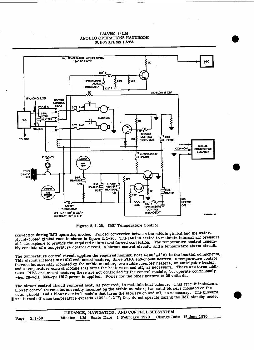
TEMPERATURE ALARM
THERMOSTAT
SK
126° F
IMU BLOWER OFF
28V, 800 CPS, 2. BLOWER CONTROL
PHASE A RELAY 0.75 AMP
0.75 AMP
PIPA HEATERS
(3) SSG HEATERS
(6)
SAFETY THERMOSTAT
OPENS AT 140° a 4.5° F CLOSES AT 137° a 3° p
139° BLOWER
CONTROL BIAS THERMOSTAT HEATER
ANTICIPATORY HEATER
130° F TEMPERATURE =
CONTROL THERMOSTAT
SIGNAL CONDITIONER
ASSEMBLY
14001414144
TO GSE
COWS 28-VDC
BUS
001513X
uw STANDBY
Off
PGNS Inv
IMU HEATER OPP 6.8K
PHASE B
STABLE MEMBER HEATERS
(2)
COMMON
=.*
BIAS HEATER
LMA790-3-LM APOLLO OPERATIONS HANDBOOK
SUBSYSTEMS DATA
Figure 2.1-25. IMU Temperature Control
convection during IMU operating modes. Forced convection between the middle gimbal and the water-glycol-cooled gimbal case is shown in figure 2.1-26. The IMU is sealed to maintain internal air pressure at 1 atmosphere to provide the required natural and forced convection. The temperature control assem-bly consists of a temperature control circuit, a blower control circuit, and'a temperature alarm circuit.
The temperature control circuit applies the required nominal heat (430 ° ±4 ° F) to the inertial components. This circuit includes six IRIG end-mount heaters, three PIPA end-mount heaters, a temperature control thermostat assembly mounted on the stable member, two stable member heaters, an anticipator heater, and a temperature control module that turns the heaters on and off, as necessary. There are three addi-tional PIPA end-mount heaters; these are not controlled by the control module, but operate continuously when 28-volt, 800-cps IRIG power is applied. Power for the other heaters is 28 volts dc.
The blower control circuit removes heat, as required, to maintain heat balance. This circuit includes a blower control thermostat assembly mounted on the stable member, two axial blowers mounted on the outer gimbal, and a blower control module that turns the blowers on and off, as necessary. The blowers
I are turned off when temperature exceeds +139 ° ±0. 2 °F; they do not operate during the IMU standby mode.
•
•
GUIDANCE, NAVIGATION, AND CONTROL SUBSYSTEM Page 2.1-50 Mission LM Basic Date 1 February 1970 Change Date 15 June 1970
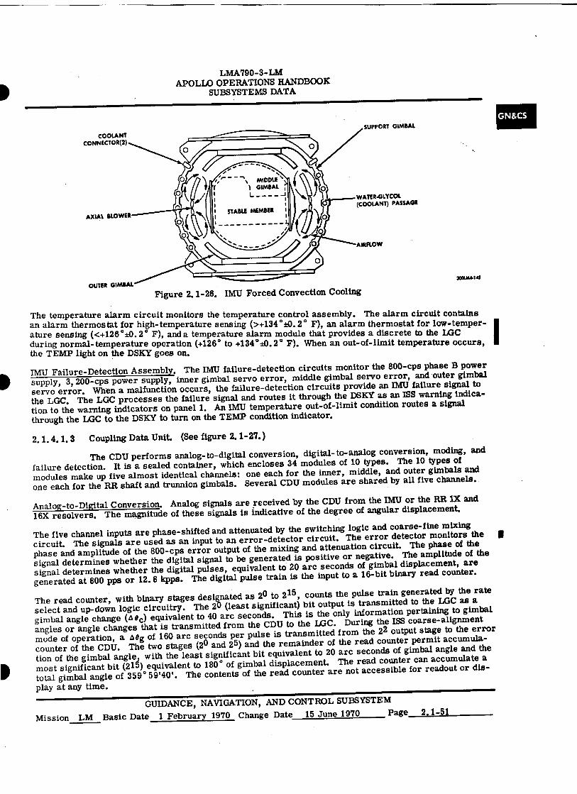
COOLANT CONNECTOR(2)
WATER-GLYCOL (COOLANT) PASSAGE
LMA790-3-LM APOLLO OPERATIONS HANDBOOK
SUBSYSTEMS DATA
OUTER GIMBAL 300im..145 Figure 2.1-26. IMU Forced Convection Cooling
The temperature alarm circuit monitors the temperature control assembly. The alarm circuit contains an alarm thermostat for high-temperature sensing (>+134 ° ±0.2 ° F), an alarm thermostat for low-temper-ature sensing (<+126 °±0.2 ° F), and a temperature alarm module that provides a discrete to the LGC during normal-temperature operation (+126 ° to +134 ° ±0.2 ° F). When an out-of-limit temperature occurs, the TEMP light on the DSKY goes on.
IMU Failure-Detection Assembly. The IMU failure-detection circuits monitor the 800-cps phase B power supply, 3, 200-cps power supply, inner gimbal servo error, middle gimbal servo error, and outer gimbal servo error. When a malfunction occurs, the failure-detection circuits provide an IMU failure signal to the LGC. The LGC processes the failure signal and routes it through the DSKY as an ISS warning indica-tion to the warning indicators on panel 1. An IMU temperature out-of-limit condition routes a signal through the LGC to the DSKY to turn on the TEMP condition indicator.
2.1.4.1.3 Coupling Data Unit. (See figure 2.1-27.)
The CDU performs analog-to-digital conversion, digital-to-analog conversion, moding, and failure detection. It is a sealed container, which encloses 34 modules of 10 types. The 10 types of modules make up five almost identical channels: one each for the inner, middle, and outer gimbals and one each for the RR shaft and trunnion gimbals. Several CDU modules are shared by all five channels.
Analog-to-Digital Conversion. Analog signals are received by the CDU from the IMU or the RR 1X and 16X resolvers. The magnitude of these signals is indicative of the degree of angular displacement.
The five channel inputs are phase-shifted and attenuated by the switching logic and coarse-fine mixing circuit. The signals are used as an input to an error-detector circuit. The error detector monitors the phase and amplitude of the 800-cps error output of the mixing and attenuation circuit. The phase of the signal determines whether the digital signal to be generated is positive or negative. The amplitude of the signal determines whether the digital pulses, equivalent to 20 arc seconds of gimbal displacement, are generated at 800 pps or 12.8 kpps. The digital pulse train is the input to a 16-bit binary read counter.
The read counter, with binary stages designated as 2 0 to 2 15 , counts the pulse train generated by the rate select and up-down logic circuitry. The 20 (least significant) bit output is transmitted to the LGC as a gimbal angle change (A 8 c) equivalent to 40 arc seconds. This is the only information pertaining to gimbal angles or angle changes that is transmitted from the CDU to the LGC. During the ISS coarse-alignment mode of operation, a o eg of 160 arc seconds per pulse is transmitted from the 2 2 output stage to the error counter of the CDU. The two stages (2 0 and 25) and the remainder of the read counter permit accumula-tion of the gimbal angle, with the least significant bit equivalent to 20 arc seconds of gimbal angle and the most significant bit (215) equivalent to 180 ° of gimbal displacement. The read counter can accumulate a total gimbal angle of 359 ° 59'40'. The contents of the read counter are not accessible for readout or dis-play at any time.
GUIDANCE, NAVIGATION, AND CONTROL SUBSYSTEM Mission LM Basic Date 1 February 1970 Change Date 15 June 1970 Page 2.1-51
GN&CS
I
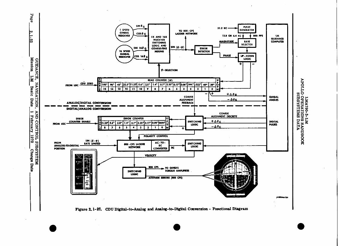
MAGNITUDE RATE SELECTOR
512 KC
IN
=I=
ERROR COUNTER
mm
11.2r 5.6• 2.1• Le or 0.35• 0.17• 0.08•
1 . 7 II 7 6 5 4 3 2 I
FROM LGC
ERROR COUNTER ENABLE
SIN 8 0
TO 800 LADDER
SIN (0 -#)
- CPS NETWORK
1X AND 16X RESOLVER
SWITCHING LOGIC AND
COARSE-FINE MIXING
1 SPEED P-
GIMBAL COS 0 G RESOLVER ••••••
SIN 160 ERROR 16 SPEED GIMBAL
RESOLVEt COS 16 6 0
DETECTOR
UP - DOWN LOGIC
FROM LGC CD1.1 ZERO
FROM ANALOG-TO-DIGITAL PORTION ,
SIN (0 -*) RATE UMITED
- SELECTION
READ COUNTER (*)
-.-- mm
180• I 90• 45• 22.5• 11.25• 5.6• 2.8• 1.4• 0.7. 0.35• 0.17. 0.08• .044 • .022• 40" 20"
15 14 13 12 11 10 9 8 7 6 5 4 3 2 1 0
+AEG
e
1■11 11MMIIMM IMMIM• =NM •111■• 111■1
+e9c
—A8c
POLARITY CONTROL
SWITCHING LOGIC
ANALOG/DIGITAL CONVERSION
DIGITALIANALOG CONVERSION 111.■
COARSE ALIGNMENT
FEEDBACK
SWITCHING LOGIC
COARSE ALIGNMENT DISCRETE
SOO - CPS LADDER NETWORK
AC - TO. DC
CONVERTER DC
#4001A14154
LM GUIDANCE COMPUTER
GIMBAL ANGLES
DIGITAL PULSES
Figure 2.1-27. CDU Digital-to-Analog and Analog-to-Digital Conversion - Functional Diagram
O
CA 0
ti
0°41 It14 g tl 1-3
0 Z
>1-3 8 ti, 8
oa
C.,71
4■11
• • •
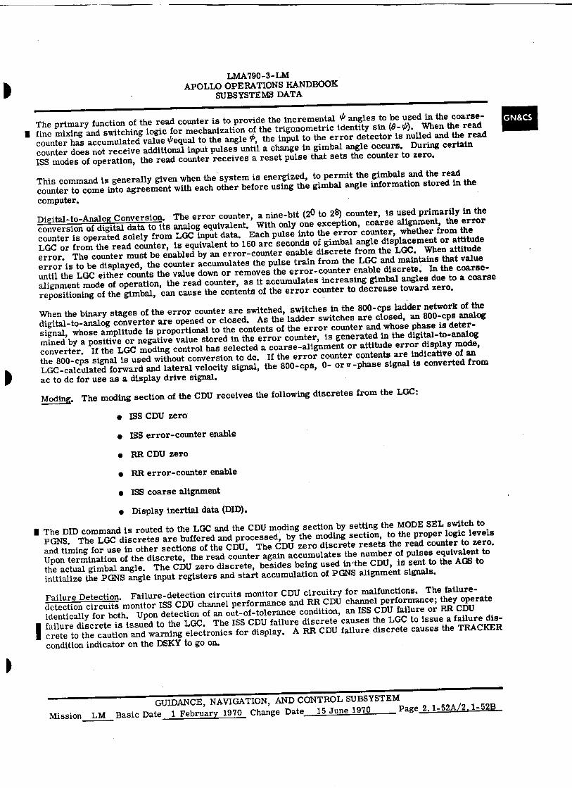
LMA790-3- LM APOLLO OPERATIONS HANDBOOK
SUBSYSTEMS DATA
GN&CS The primary function of the read counter is to provide the incremental angles to be used in the coarse- ■ fine mixing and switching logic for mechanization of the trigonometric identity sin (8-0). When the read
counter has accumulated value 'equal to the angle 9s, the input to the error detector is nulled and the read counter does not receive additional input pulses until a change in gimbal angle occurs. During certain ISS modes of operation, the read counter receives a reset pulse that sets the counter to zero.
This command is generally given when the system is energized, to permit the gimbals and the read counter to come into agreement with each other before using the gimbal angle information stored in the computer.
Digital-to-Analog Conversion. The error counter, a nine-bit (2 0 to 28) counter, is used primarily in the conversion of digital data to its analog equivalent. With only one exception, coarse alignment, the error counter is operated solely from LGC input data. Each pulse into the error counter, whether from the LGC or from the read counter, is equivalent to 160 arc seconds of gimbal angle displacement or attitude error. The counter must be enabled by an error-counter enable discrete from the LGC. When attitude error is to be displayed, the counter accumulates the pulse train from the LGC and maintains that value until the LGC either counts the value down or removes the error-counter enable discrete. In the coarse- alignment mode of operation, the read counter, as it accumulates increasing gimbal angles due to a coarse repositioning of the gimbal, can cause the contents of the error counter to decrease toward zero.
When the binary stages of the error counter are switched, switches in the 800-cps ladder network of the digital-to-analog converter are opened or closed. As the ladder switches are closed, an 800-cps analog signal, whose amplitude is proportional to the contents of the error counter and whose phase is deter-mined by a positive or negative value stored in the error counter, is generated in the digital-to-analog converter. If the LGC moding control has selected a coarse-alignment or attitude error display mode, the 800-cps signal is used without conversion to dc. If the error counter contents are indicative of an LGC-calculated forward and lateral velocity signal, the 800-cps, 0- or if-phase signal is converted from ac to dc for use as a display drive signal.
ModinK. The moding section of the CDU receives the following discretes from the LGC:
• ISS CDU zero
• ISS error-counter enable
• RR CDU zero
• RR error-counter enable
• ISS coarse alignment
• Display inertial data (DID).
I The DID command is routed to the LGC and the CDU moding section by setting the MODE SEL switch to PGNS. The LGC discretes are buffered and processed, by the moding section, to the proper logic levels and timing for use in other sections of the CDU. The CDU zero discrete resets the read counter to zero. Upon termination of the discrete, the read counter again accumulates the number of pulses equivalent to the actual gimbal angle. The CDU zero discrete, besides being used inthe CDU, is sent to the AGS to initialize the PGNS angle input registers and start accumulation of PGNS alignment signals.
Failure Detection. Failure-detection circuits monitor CDU circuitry for malfunctions. The failure-detection circuits monitor ISS CDU channel performance and RR CDU channel performance; they operate identically for both. Upon detection of an out-of-tolerance condition, an ISS CDU failure or RR CDU
I failure discrete is issued to the LGC. The ISS CDU failure discrete causes the LGC to issue a failure dis-crete to the caution and warning electronics for display. A RR CDU failure discrete causes the TRACKER condition indicator on the DSKY to go on.
GUIDANCE, NAVIGATION, AND CONTROL SUBSYSTEM Mission LM Basic Date 1 February 1970 Change Date 15 June 1970 Page 2.1-52A/2.1-52B

•
S
•
• LMA790-3-LM APOLLO OPERATIONS HANDBOOK
SUBSYSTEMS DATA
2.1.4.1.4 Pulse Torque Assembly.
The PTA consists of 17 electronic modular subassemblies mounted on a common base. There are four binary current switches. One furnishes torquing current to the three IRIG's and the other three furnish torquing current to the three PIPA's. The four d-c differential amplifier and precision voltage reference subassemblies regulate torquing current supplied through the binary current switches.
The three a-c differential amplifier and interrogator subassemblies amplify'accelerometer signal generator signals and convert them to plus and minus torque pulses. The gyro calibration module applies plus or minus torquing current to the IRIG's when commanded by the LGC. The three PIPA cali-bration modules compensate for the differences in inductive loading of accelerometer torque generator windings and regulate the balance of plus and minus torque. A pulse torque isolation transformer couples torque commands, data pulses, interrogate pulses, switching pulses, and synchronizing pulses between the LGC and PTA. Power for the other 16 subassemblies is supplied by the pulse torque power supply.
2.1.4.1.5 Power and Servo Assembly.
The PSA provides a central point for the PGNS amplifiers, modular electronic components, and power supplies. The PSA is on the cabin bulkhead behind the astronauts., It consists of 14 subas-semblies mounted to a header assembly. Connectors and harnesses are integral to the header assembly. A thin cover plate, mounted on the PSA, hermetically seals the assembly. During flight, this permits pressurization of the PSA to remain at 15 psi.
The three gimbal servoamplifiers supply the torquing signals for the IMU gimbals. IMU moding is accomplished by the relay module. A -28-volt d-c power supply supplies power to the gimbal servoamplifiers and pulse torque power supply. The PSA contains one amplifier and one automatic amplitude control, filter, and multivibrator subassembly for the 3, 200-cps, A power supply. The ampli-fier supplies 28 volts, 3,200 cps, to the ducosyn transformer on the stable member and to the gimbal servoamplifiers; the automatic amplitude control, filter, and multivibrator subassembly regulates ampli-fier operation.
An amplifier and an automatic amplitude control, filter and multivibrator subassembly is also associated with the 800-cps power supply. This amplifier supplies 28 volts, 800 cps, for IMU re-solver excitation and provides a reference signal for an 800-cps, 5% amplifier, which in turn provides a reference for another 800-cps, 5% amplifier. These two amplifiers, 90 ° apart in phase, supply 28 volts, 800 cps, for the IMU blowers, gyro wheels, and the PIPA heaters. The IMU load compensation subas-sembly provides power-factor correction for 800-cps, 1%, and 5% supplies.. The 28-volt IMU operate power from the CDR's 28-volt d-c bus is filtered by the PGNS supply filter subassembly.
The IMU auxiliary subassembly indicates to IS an out-of-tolerance condition of 3, 200-cpa; the 28-volt, 800-cps, 1%; and the 28-volt, 809-cps, 5%; and the gimbal error signals; provides IMU turn-on moding discretes; and indicates IMU temperature out-of-tolerance condition to GSE through the umbilical of the launch tower (LUT).
2.1.4.1.6 Signal Conditioner Assembly.
The SCA preconditions PGNS measurements to a 0- to 5-volt d-c format before the signals are routed to the IS. There are three types of SCA output signals: PB, PU, and PD. The PB type are preconditioned analog signals derived from a bipolar signal. The PU type are preconditioned analog signals derived from a unipolar signal. The PD type are preconditioned bilevel discretes. The PB type identifies signals that are referenced to the 2. 5-volt d-c bias supply. The SCA consists of four signal-conditioning modules, which are listed, with signal description and telemetry number, in table 2.1-2. The SCA is mounted piggyback on the PSA.
The gimbal resolver signal-conditioning module conditions the inner, middle, and outer gimbal resolver sine and cosine signals.
The IRIG and PIPA signal-conditioning module conditions the inner, middle, and outer gimbal IRIG error signals and the X-, Y-, and Z-PIPA error signals. This module also generates a 3, 200-cps, square-wave reference signal required to operate the SCA circuits.
GN&CS
GUIDANCE, NAVIGATION, AND CONTROL SUBSYSTEM Mission LM Basic Date 1 February 1970 Change Date 15 June 1970 Page 2.1-53
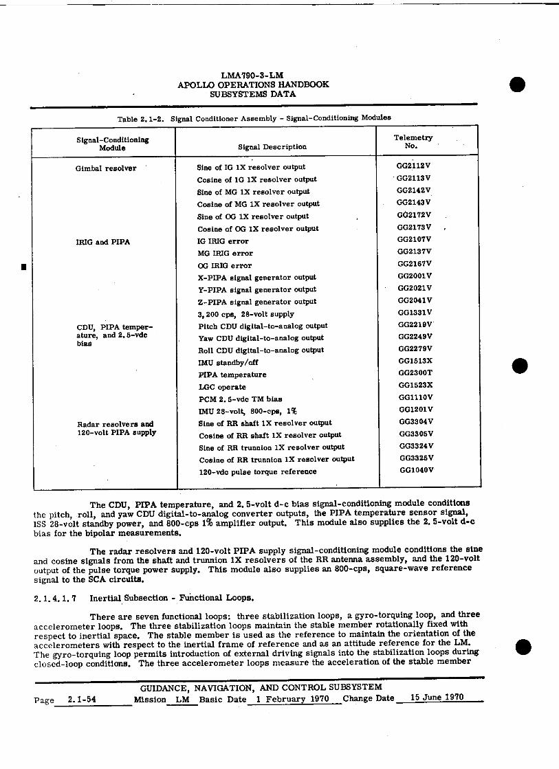
LMA790-3-LM APOLLO OPERATIONS HANDBOOK
SUBSYSTEMS DATA
Table 2.1-2. Signal Conditioner Assembly - Signal-Conditioning Modules
Signal-Conditioning Module Signal Description
Telemetry No.
• Gimbal resolver Sine of IG IX resolver output GG2112V
Cosine of 10 1X resolver output • GG2113V
Sine of MG 1X resolver output GG2142V
Cosine of MG 1X resolver output GG2143V
Sine of CG 1X resolver output GG2172V
Cosine of OG IX resolver output GG2173 V
IRIG and PIPA IG IRIG error GrG2107V
MG IRIG error GG2137V
OG IRIG error GG2167V
X-PIPA signal generator output GG2001 V
Y-PIPA signal generator output GG2021V
Z-PIPA signal generator output GG2041V
3,200 cps, 28-volt supply GG1331V
CDU, PIPA temper- ature, and 2.5-vdc bias
Pitch CDU digital-to-analog output
Yaw CDU digital-to-analog output
GG2219V
GG2249V
Roll CDU digital-to-analog output GG2279V
IMU standby/off GG1513X
PIPA temperature GG2300T
LGC operate GG1523X
PCM 2. 5-vdc TM bias GG1110V
IMU 28-volt, 800-cps, 1% GG1201V
Radar resolvers and Sine of RR shaft 1X resolver output GG3304 V 120-volt PIPA supply Cosine of RR shaft 1X resolver output GG3305V
Sine of RR trunnion lx resolver output GG3324 V
Cosine of RR trunnion IX resolver output GG3325V
120-vdc pulse torque reference GG1040V
The CDU, PIPA temperature, and 2.5-volt d-c bias signal-conditioning module conditions the pitch, roll, and yaw CDU digital-to-analog converter outputs, the PIPA temperature sensor signal, ISS 28-volt standby power, and 800-cps 1% amplifier output. This module also supplies the 2.5-volt d-c bias for the bipolar measurements.
The radar resolvers and 120-volt PIPA supply signal-conditioning module conditions the sine and cosine signals from the shaft and trunnion 1X resolvers of the RR antenna assembly, and the 120-volt output of the pulse torque power supply. This module also supplies an 800-cps, square-wave reference signal to the SCA circuits.
2.1.4.1. rt Inertial Subsection - Functional Loops.
There are seven functional loops: three stabilization loops, a gyro-torquing loop, and three accelerometer loops. The three stabilization loops maintain the stable member rotationally fixed with respect to inertial space. The stable member is used as the reference to maintain the orientation of the accelerometers with respect to the inertial frame of reference and as an attitude reference for the LM. The gyro-torquing loop permits introduction of external driving signals into the stabilization loops during closed-loop conditions. The three accelerometer loops measure the acceleration of the stable member
•
Mission LM Basic Date 1 February 1970 Change Date 15 June 1970 Page 2.1-54 GUIDANCE, NAVIGATION, AND CONTROL SUBSYSTEM
• LMA790-3-LM APOLLO OPERATIONS HANDBOOK
SUBSYSTEMS DATA
along three orthogonal axes and integrate these data to determine velocity. The LGC uses the velocity data to compute LM trajectory. The accelerometer loops also generate torquing signals for torquing the PIPA's back to a null position after sensing an acceleration.
Stabilization Loops. (See figure 2. 1-28,) When the stabilization loops hold the stable member inertially referenced, any movement of the stable member is sensed by one or more of the three IRIG's. This re-sults in an TRIG-signal-generator, 3, 200-cps, error-signal output, which is proportional to the rotation of the gyro about its input axis. This error signal is then amplified by a preamplifier, which is an integral part of the TRIG assembly. The Y-gyro error signal passes directly to the associated gimbal servoampli-fier through the normally closed contacts of the coarse-alignment relay. The X- and Z-gyro error signals are resolved about the IGA by the gyro error resolver before being introduced to the associated gimbal servoamplifiers. The servoamplifier current output is fed to the appropriate gimbal torque motor to re-store the stable member to its original reference position. As the stable member is returned to its origi-nal reference position, the movement sensed by the IRIG is opposite in direction but equal in magnitude to the disturbance input; the result is precession of the float. Due to precession, the float returns to its null position. Because no signal-generator output is then present, the loop is nulled and no further drive sig-nals are applied until another disturbance is introduced.
Resolution of the X- and Z-gyro error signals is required because motion about the MGA or the OGA, with the stable member at some angle other than O D , is sensed by the X-gyro and Z-gyro. The resolver then sums the components of gyro error that lie along the MGA or OGA and directs the gyro errors to the ap-plicable gimbal servoamplifier.
When the stabilization loops are initially energized, the stable member is referenced to the LM axes by driving the gimbals with an error signal inserted at the coarse-alignment input to the gimbal servoampli-fiers (coarse-alignment relay energized). If a specific inertial reference is desired, the stable member is aligned to the desired orientation, using the stabilization loops. The alignment is accomplished in two
10 steps: coarse-alignment moding and fine-alignment moding. During coarse alignment, the gyro error sig- nals are disconnected from the gimbal servoamplifiers. Instead, 800-cps error signals are injected through the coarse-alignment relay to torque the gimbals to approximately the desired position. For fine alignment of the stable member, the coarse-alignment relay is deenergized and gyro error signals are injected in the loops for additional gimbal torquing. The gyro error signals are generated by torquing the IRIG's with pulses originating at the LGC and processed through the pulse torque or fine-alignment elec-tronics loop. The stable member is then aligned and the stabilization loops hold it in this final position.
Gyro-Torquing Loop. (See figure 2.1-28.) Using a torque generator to torque the [RIG floats, it is pos-sible to drive the IMU gimbals to new positions. This permits fine alignment of the stable member to a desired reference with considerable accuracy. When gyro torquing is required during the fine-alignment mode of operation, the LGC issues pulses, which are controlled by program 52, that:
• Enable the torquing electronics
• Select the gyro to be torqued
• Select the direction of torquing
• Control the amount of torque applied.
The three IRIG's are sequentially torqued by the LGC during fine alignment; it is possible for all three gyros to be controlled through one set of torquing electronics. The torquing electronics consists of a gyro calibration module, a binary current switch, a d-c differential amplifier and precision voltage refer-ence module, and a pulse torque power supply module.
Basically, the gyro-torquing loop operates by applying a constant current to the torque windings in the IRIG. When torque pulses and gyro select pulses are initiated by the LGC, a constant direct current is applied to an IRIG and the float is torqued a specific amount; a specific amount of IMU gimbal rotation is provided. The number or torque (set) pulses applied to the current switch determines how long the torqu-ing current is applied. The gyro select pulses enable a switching network (in the gyro calibration module), which closes a current path through a specific winding in a specific gyro for positive or negative torquing of the float. Before and after torquing, the LGC issues no-torque (reset) pulses to the current switch,
GUIDANCE, NAVIGATION, AND CONTROL SUBSYSTEM
Mission LM Basic Date 1 February 1970 Change Date 15 June 1970 Page 2.1-55
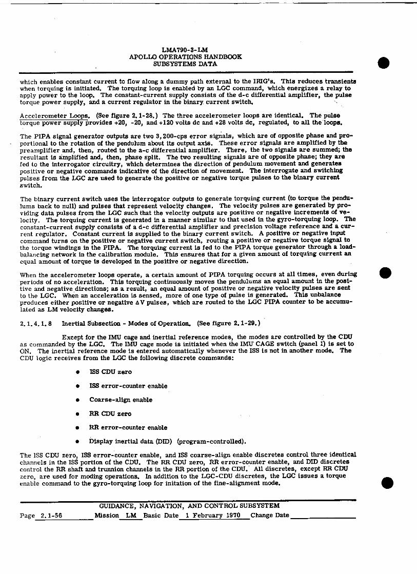
LMA790-3-LM APOLLO OPERATIONS HANDBOOK
SUBSYSTEMS DATA
which enables constant current to flow along a dummy path external to the IRIG's. This reduces transients when torquing is initiated. The torquing loop is enabled by an LGC command, which energizes a relay to apply power to the loop. The constant-current supply consists of the d-c differential amplifier, the pulse torque power supply, and a current regulator in the binary current switch.
Accelerometer Loops. (See figure 2.1-28.) The three accelerometer loops are identical. The pulse torque power supply provides +20, -20, and +120 volts de and +28 volts dc, regulated, to all the loops.
The PIPA signal generator outputs are two 3, 200-cps error signals, which are of opposite phase and pro-portional to the rotation of the pendulum about its output axis. These error signals are amplified by the preamplifier and, then, routed to the a-c differential amplifier. There, the two signals are summed; the resultant is amplified and, then, phase split. The two resulting signals are of opposite phase; they are fed to the interrogator circuitry, which determines the direction of pendulum movement and generates positive or negative commands indicative of the direction of movement. The interrogate and switching pulses from the LGC are used to generate the positive or negative torque pulses to the binary current switch.
The binary current switch uses the interrogator outputs to generate torquing current (to torque the pendu-lums back to null) and pulses that represent velocity changes. The velocity pulses are generated by pro-viding data pulses from the LGC such that the velocity outputs are positive or negative increments of ve-locity. The torquing current is generated in a manner similar to that used in the gyro-torquing loop. The constant-current supply consists of a d-c differential amplifier and precision voltage reference and a cur-rent regulator. Constant current is supplied to the binary current switch. A positive or negative input command turns on the positive or negative current switch, routing a positive or negative torque signal to the torque windings in the PIPA. The torquing current is fed to the PIPA torque generator through a load-balancing network in the calibration module. This ensures that for a given amount of torquing current an equal amount of torque is developed in the positive or negative direction.
When the accelerometer loops operate, a certain amount of PIPA torquing occurs at all times, even during periods of no acceleration. This torquing continuously moves the pendulums an equal amount in the posi-tive and negative . directions; as a result, an equal amount of positive or negative velocity pulses are sent to the LGC. When an acceleration is sensed, more of one type of pulse is generated. This unbalance produces either positive or negative AV pulses, which are routed to the LGC PIPA counter to be accumu-lated as LM velocity changes.
2.1.4.1.8 Inertial Subsection - Modes of Operation. (See figure 2.1-29.)
Except for the IMU cage and inertial reference modes, the modes are controlled by the CDU as commanded by the LGC. The IMU cage mode is initiated when the IMU CAGE switch (panel I) is set to ON. The inertial reference mode is entered automatically whenever the ISS is not in another mode. The CDU logic receives from the LGC the following discrete commands:
• ISS CDU zero
• ISS error-counter enable
• Coarse-align enable
• RR CDU zero
• RR error-counter enable
• Display inertial data (DID) (program-controlled).
The ISS CDU zero, ISS error-counter enable, and ISS coarse-align enable discretes control three identical channels in the ISS portion of the CDU. The RR CDU zero, RR error-counter enable, and DID discretes control the RR shalt and trunnion channels in the RR portion of the CDU. All discretes, except RR CDU zero, are used for moding operations. In addition to the LGC-CDU discretes, the LGC issues a torque enable command to the gyro-torquing loop for initation of the fine-alignment mode.
GUIDANCE, NAVIGATION, AND CONTROL SUBSYSTEM
Page 2.1 - 56 Mission LM Basic Date 1 February 1970 Change Date
•
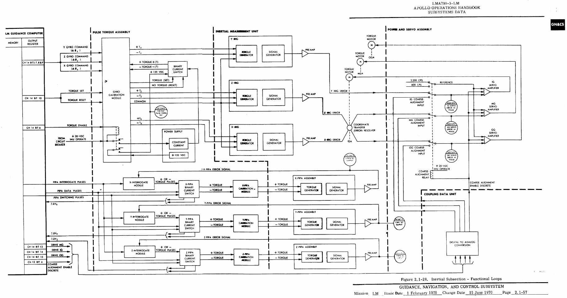
LMA790-3-LM APOLLO OPERATIONS HANDBOOK
SUBSYSTEMS DATA
I POWER AND SERVO ASSEMBLY INERTIAL MEASUREMENT UNIT PULSE TORQUE ASSEMBLY LM GUIDANCE COMPUTER
TORQUE MOTOR OUTPUT
REGISTER MEMORY
Y GYRO COMMAND + T y
PRE AMP —T r MOSQUE
ODIERATOR SIGNAL
GENERATOR TORQUE MOTOR
Z GYRO COMMAND
( "z ) CM 14 BITS 7, 889 + TORQUE +(T)
X GYRO COMMAND (A e g )
BINARY CURRENT SWITCH
— TORQUE — (T) I TORQUE
MOTOR
CT)MGA + 120 VDC
I TORQUE (SET) tia I 3 200 CPS
-11IG 10 SERVO- ,4(MPLIFIER
REFERENCE NO TORQUE •(RESET) BOO CPS
ERROR
0 TORQUE SET + T GYRO
CALIBRATION MODULE
Y BOG
I >it AMP — T 1 TORQUE GMITITIATOR
SIGNAL
GENERATOR CH II BIT 10 1••
TORQUE RESET IG COARSE- ALIGNMENT
INPUT
COMMON
MG SERVO-
exmPLIF IER I NG ERROR •
+Tx
— Tx 0
MG COARSE- ALIGNMENT
INPUT TORQUE ENABLE COORDINATE
TRANSFER (ERROR) RESOLVER
CH 14 BIT 6 X -IRIG
I POWER SUPPLY OG SERVO-
AMPLIFIER I + 28-VDC IMU OPERATE FROM
CIRCUIT BREAKER
I PREAMP IORQUE
GHTIRATOR SIGNAL
GENERATOR 1-111G ERROR
CONSTANT
CURRENT
IGA
O OG COARSE-
ALIGNMENT INPUT GG1 67v
+ 120 VDC OG $ Po0 ERROR IRE
PHAS E L I ER∎ R
I + 28-VDC IMU OPERATE
COARSE- ALIGNMENT
RELAY
I X PIPA ERROR SIGNAL
I X •PIPA ASSEMBLY + OR — TORQUE PULSES
• I I I I I
1
PIPA INTERROGATE PULSES X•INTERROGATE MODULE 1 X-PIPA
BINARY CURRENT SWITCH
COARSE ALIGNMENT
ENABLE DISCRETE
•■■•
I + TORQUE TORQUE]
GENERATOR
+ TORQUE PRE AMP 11-PIPA SIGNAL
GENERATOR CARNATION .
ITODVLE PIPA DATA PULSES — TORQUE — TORQUE
=MED =MIMED =MM. ■I•11
COUPLING DATA UNIT PIPA SWITCHING PULSES I LIVx Y-PIPA ERROR SIGNAL
r Y-PIPA ASSEMBLY + OR — TORQUE PULSES Y•INTERROGATE
MODULE Y-PIPA BINARY
CURRENT SWITCH
+ TORQUE + TORQUE TAPA URINATION
MODULE
3 Amp • TORQUE
GENERATOR SIGNAL
GENERATOR — TORQUE — TORQUE
I ± AY,
+,v,
DRIVE MG
DRIVE IG
DRIVE OG
Z-PIPA ERROR SIGNAL
DIGITAL TO ANALOG CONVERSION I
I I I
CM 14 BIT 13
CH 14 BIT 14
CM 14 BIT 15
CM 12 BIT 4
+ OR — TORQUE PULSES
Z -PIPA ASSEMBLY Z•INTERROGATE
MODULE Z•PIPA BINARY
CURRENT SWITCH
+ TORQUE
—TORQUE
+ TORQUE PRE AMP 1-1 PA CARNATION
• ODULE
TORQUE GENERATOR
SIGNAL GENERATOR — TORQUE
COARSE ALIGNMENT ENABLE DISCRETE
Figure 2.1-28. Inertial Subsection - Functional Loops
GUIDANCE, NAVIGATION, AND CONTROL SUBSYSTEM
Mission LM Basic Date 1 February 1970 Change Date 15 June 1970 Page 2.1-57
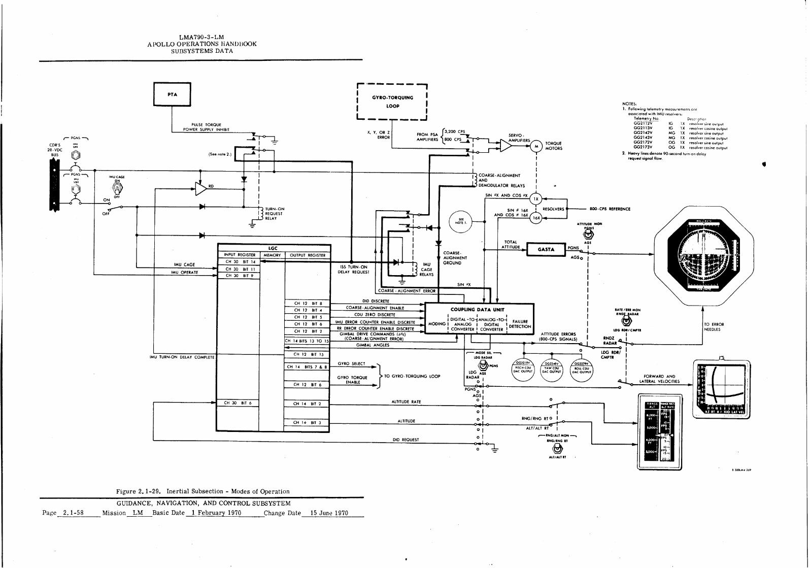
LMA790-3-LM APOLLO OPERATIONS HANDBOOK
SUBSYSTEMS DATA
1
(See note 2.)
• IMU CAGE
ON
OFF ON
TURN. ON
OFF 1 5 REQUEST RELAY
LGC INPUT REGISTER MEMORY OUTPUT REGISTER
CH 30 BIT 14 —
BIT 11 CH 30
CH 30 i BIT 9
CH 12 BIT 8
CH 12 BIT 4
CH 12 BIT 5
CH 12 BIT 6
CH 12 BIT 2
CH 13 15 14 BITS TO
CH 12 BIT 15
CH 14 BITS 7 & 8
CH 12 BIT 6
CH 30 BIT 6 CH 14 BIT 2
e
CH 14. BIT 3
L. =MID •••■•
f ERROR 800 CPS
FROM PSA AMPLIFIERS e200 CPS
X, Y, OR Z
I
14
V
COARSE - • ALIGNMENT
GROUND
SIN 1X
IMU CAGE
RELAYS
SIN OX AND COS /X
SIN 0 16X AND COS P 16X
I RESOLVERS
TO ERROR
NEEDLES
RATE /ERR MON NO4ADAR
GYRO SELECT
GYRO TORQUE ENABLE
TO GYRO . TORQUING LOOP
r GYRO-TORQUING
LOOP
1—""
[SS TURN -ON DELAY REQUEST
• ---- 1300• CPS REFERENCE
ATTITUDE MON
TOTAL AGS ATTITUDE GASTA PGNS
AGS 0
COARSE- ALIGNMENT AND
DEMODULATOR RELAYS
COARSE ALIGNMENT ERROR
DID DISCRETE
NOTES: 1. Following telemetry measurements are
associated with IMU resolvers:
Telemetry No. Description GG2112V IG IX resolver sine output
GG2113V IG 1 X resolver cosine output
GG2142V MG 1X resolver sine output
GG2143V MG I X resolver cosine output
GG2172V OG 1 X resolver sine output
GG2173V OG 1X resolver cosine output
2. Heavy lines denote 90-second turn-on delay
request signal flow.
SERVO . >MPLIFIERS
TORQUE MOTORS
ATTITUDE ERRORS (800-CPS SIGNALS)
FORWARD AND LATERAL VELOCITIES
RANGE RANA Rat All RATE • LT re 15 10 S 0 5 10 I "
AZ RT X.1 X10 LAT VII
COUPLING DATA UNIT I 1 i 1 DIGITA -TO-(ANALOG-TO-1 FAILURE
MOOING I ANA OG I DIGITAL I DETECTION I CONVERTER I CONVERTER I
r— MODE S L LDG RADAR
LDG NOR/CWT.
RNDZ I RADAR —.1..0 0 I LDG RCM/ ; CMPTR
GIMBAL ANGLES
ALTITUDE RATE
ALTITUDE
DID REQUEST
COARSE ALIGNMENT ENABLE
CDU ZERO DISCRETE
IMU ERROR COUNTER ENABLE DISCRETE
RR ERROR COUNTER ENABLE DISCRETE GIMBAL DRIVE COMMANDS (-0c)
(COARSE . ALIGNMENT ERROR
PGNSo I
AGS 1 O 0
O I
O I RNG/RNG RT 0 I
I tr-r* ALT/ ALT RT
r--ING/ALT MON—,
ING/ING RI
O
ALT/ALT IT
O I
O I 1
PGNS
CDR'S IMU OPN
28 VDC BUS
O r-- PGNS --\
/IN
PULSE TORQUE POWER SUPPLY INHIBIT
IMU CAGE
IMU OPERATE
IMU TURN-ON DELAY COMPLETE
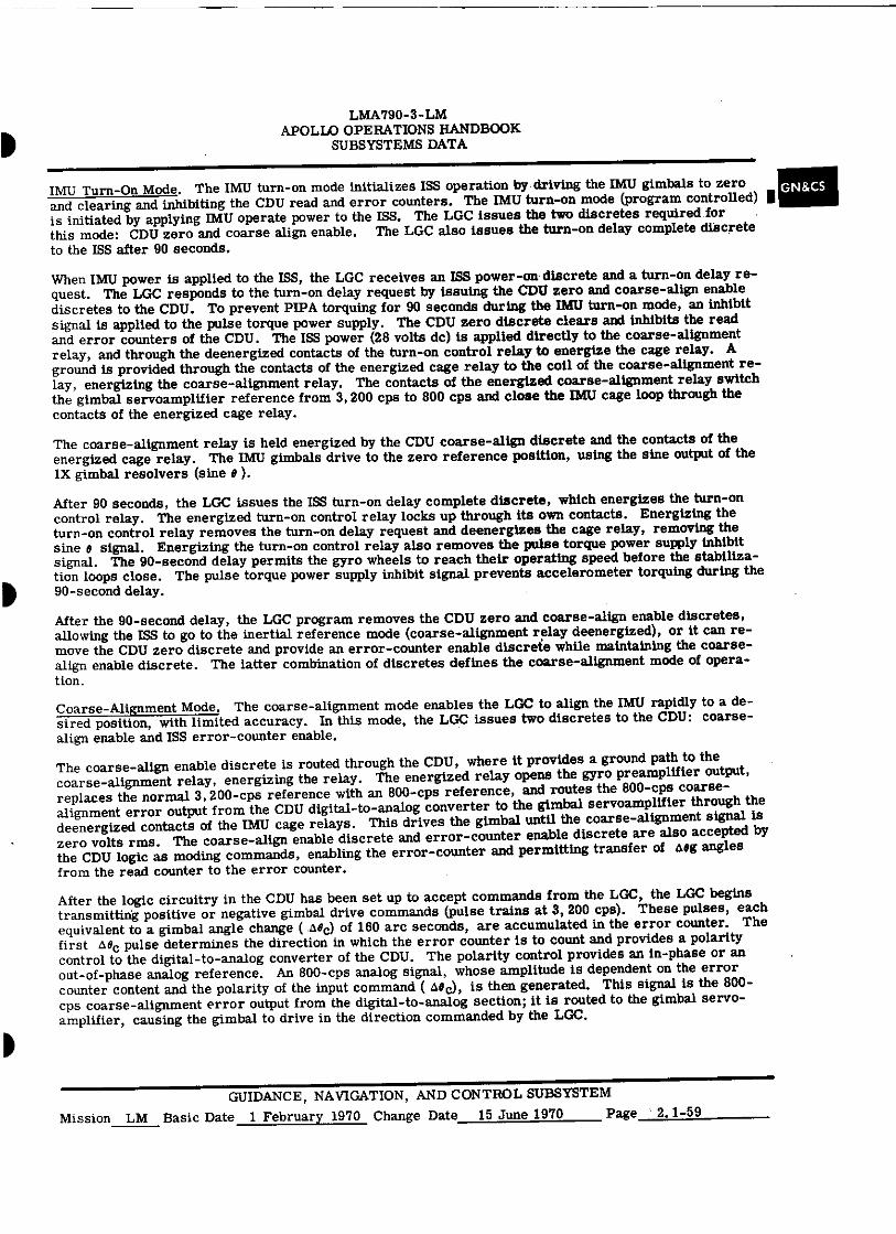
LMA790-3- LM APOLLO OPERATIONS HANDBOOK
SUBSYSTEMS DATA
IMU Turn-On Mode. The IMU turn-on mode initializes ISS operation by driving the IMU gimbals to zero and clearing and inhibiting the CDU read and error counters. The IMU turn-on mode (program controlled) I is initiated by applying IMU operate power to the ISS. The LGC issues the two discretes required for this mode: CDU zero and coarse align enable. The LGC also issues the turn-on delay complete discrete to the ISS after 90 seconds.
GN&CS
When IMU power is applied to the ISS, the LGC receives an ISS power-on discrete and a turn-on delay re-quest. The LGC responds to the turn-on delay request by issuing the CDU zero and coarse-align enable discretes to the CDU. To prevent PIPA torquing for 90 seconds during the IMU turn-on mode, an inhibit signal is applied to the pulse torque power supply. The CDU zero discrete clears and inhibits the read and error counters of the CDU. The ISS power (28 volts dc) is applied directly to the coarse-alignment relay, and through the deenergized contacts of the turn-on control relay to energize the cage relay. A ground is provided through the contacts of the energized cage relay to the coil of the coarse-alignment re-lay, energizing the coarse-alignment relay. The contacts of the energized coarse-alignment relay switch the gimbal servoamplifier reference from 3,200 cps to 800 cps and close the IMU cage loop through the contacts of the energized cage relay.
The coarse-alignment relay is held energized by the CDU coarse-align discrete and the contacts of the energized cage relay. The IMU gimbals drive to the zero reference position, using the sine output of the 1X gimbal resolvers (sine 0 ).
After 90 seconds, the LGC issues the ISS turn-on delay complete discrete, which energizes the turn-on control relay. The energized turn-on control relay locks up through its own contacts. Energizing the turn-on control relay removes the turn-on delay request and deenergizes the cage relay, removing the sine B signal. Energizing the turn-on control relay also removes the pulse torque power supply inhibit signal. The 90-second delay permits the gyro wheels to reach their operating speed before the stabiliza-tion loops close. The pulse torque power supply inhibit signal prevents accelerometer torquing during the 90-second delay.
After the 90-second delay, the LGC program removes the CULT zero and coarse-align enable discretes, allowing the ISS to go to the inertial reference mode (coarse-alignment relay deenergized), or it can re-move the CDU zero discrete and provide an error-counter enable discrete while maintaining the coarse-align enable discrete. The latter combination of discretes defines the coarse-alignment mode of opera-tion.
Coarse-Alignment Mode. The coarse-alignment mode enables the LGC to align the IMU rapidly to a de-sired position, with limited accuracy. In this mode, the LGC issues two discretes to the CDU: coarse-align enable and ISS error-counter enable.
The coarse-align enable discrete is routed through the CDU, where it provides a ground path to the coarse-alignment relay, energizing the relay. The energized relay opens the gyro preamplifier output, replaces the normal 3, 200-cps reference with an 800-cps reference, and routes the 800-cps coarse-alignment error output from the CDU digital-to-analog converter to the gimbal servoamplifier through the deenergized contacts of the IMU cage relays. This drives the gimbal until the coarse-alignment signal is zero volts rms. The coarse-align enable discrete and error-counter enable discrete are also accepted by the CDU logic as moding commands, enabling the error-counter and permitting transfer of Aeg angles from the read counter to the error counter.
After the logic circuitry in the CDU has been set up to accept commands from the LGC, the LGC begins transmitting positive or negative gimbal drive commands (pulse trains at 3,200 cps). These pulses, each equivalent to a gimbal angle change ( AN0c) of 160 arc seconds, are accumulated in the error counter. The first a0c pulse determines the direction in which the error counter is to count and provides a polarity control to the digital-to-analog converter of the CDU. The polarity control provides an in-phase or an out-of-phase analog reference. An 800-cps analog signal, whose amplitude is dependent on the error counter content and the polarity of the input command ( a0 c), is then generated. This signal is the 800-cps coarse-alignment error output from the digital-to-analog section; it is routed to the gimbal servo-amplifier, causing the gimbal to drive in the direction commanded by the LGC.
GUIDANCE, NAVIGATION, AND CONTROL SUBSYSTEM Mission LM Basic Date 1 February 1970 Change Date 15 June 1970 Page ' 2.1-59
LMA790 -3- LM APOLLO OPERATIONS HANDBOOK
SUBSYSTEMS DATA
The changing gimbal angles are detected by the error-detector circuits in the CDU. These detected errors permit a pulse train, at 6, 400 pps, to increase the read counter. The increasing read counter nulls the sine and cosine voltage inputs to the error-detector circuits from the IMU 1X and 16X resolvers.
As the read counter is being incremented, one output of the counter, representing a 40-arc-second-per-pulse increase in gimbal angle, is routed to the LGC. Another output of the counter, representing 160 arc seconds per pulse, is recognized in the CDU logic as an incremental value to be entered into the error counter in a direction opposite to that of the LGC-commanded +Nee. If aac is positive, the error counter counts up and the aeg from the read counter decreases the counter. For each counter pulse into the error counter, the total content decreases. This decreases the digital-to-analog converter output and, there-fore, the rate of drive. When the number of digital feedback pulses equals the LGC-commanded number of pulses, the error counter is empty and the digital-to-analog converter output should be zero.
The rate of drive of the gimbals during coarse alignment is limited to a maximum of 35 ° per second. This is due to degenerative feedback provided within the CDU mechanization.
Fine-Alignment Mode. (See figures 2.1-28 and 2.1-29.) The fine-alignment mode allows the LGC to position the IMU accurately to a predetermined gimbal angle, closer than 40 arc seconds of CDU toler-ance, since each gyro-torquing pulse is equal to 0.615 arc second of displacement. The LGC does not issue any discretes to the CDU during this mode of operation; therefore, the read counter circuitry re-peats the changing gimbal angles exactly as was done in the coarse-alignment mode. The LGC keeps track of the gimbal angle to within 40 arc seconds.
The commanding signals for the fine-alignment mode are issued to the time-shared fine-alignment or pulse torque electronics. The LGC first -issues a torque enable discrete, which applies 28 and 120 volts dc to the binary current switch, a differential amplifier, and a precision voltage reference circuit, allowing the circuit to become operative. The current switch is reset by the no-torque pulses, allowing a dummy current, which is equal to the torquing current, to flow. This allows the current to settle to a constant value before it. is used for gyro torquing. A gyro is then selected (gyro select pulses) for either (positive or negative) torquing current. After the discretes have been issued, the LGC sends torque (set) pulses or fine-alignment commands to the set side of the current switch. The pulse allows the selected torquing current (positive or negative) to flow through the gyro windings, causing the float to move. The resulting signal generator output causes the stable member to be driven through an angle equal to the command angle. The LGC receives inputs from the CDU read counter that indicate a 40-arc-second-per-pulse change in gimbal angle.
The number of torquing pulses sent from the LGC to the torquing electronics is computed on the basis of gimbal angle at an instant of time and a desired alignment angle. The difference is converted into the number of pulses necessary to drive the gimbal through the difference angle. The required number of fine-alignment pulses is computed only once; it is not recomputed on the basis of gimbal angle after the desired number of pulses have been sent. Fine-alignment loop operation is open-loop as far as the LGC is concerned; the aeg pulses are not used for feedback.
The fine-alignment pulses generated by the LGC are issued in bursts of 3,200 pps. The fine-alignment electronics permits the torquing current to be on in the direction chosen by LGC logic, for the duration of the pulse burst. When the LGC is not issuing fine-alignment pulses or the gyro floats are not being torqued, the stable member can be considered inertially referenced.
Attitude Error Display Mode. The attitude error display mode permits the LGC to display attitude errors, in analog form, to the astronaut. In this mode, CDU error-counter enable discrete is generated by the LGC. The LGC is informed of the gimbal angle and any changes to it by the read counter and the analog-to-digital converter associated with it. The read counter output is routed through logic to the LGC, which is then aware of the current LM attitude.
A digital autopilot program (DAP) has a computed desired attitude associated with current time and LM position. The difference between the desired and actual values is attitude error. The attitude error is converted to aec pulses (each equivalent to 160 arc seconds of error), which are fed to the error counter at a rate of 3, 200 pps. The error counter is incremented to contain the number of pulses commanded. The contents of the error counter are converted to an 800-cps error signal by the digital-to-analog con-verter. The phase of the digital-to-analog converter output depends on whether the input command is a positive or negative.
GUIDANCE, NAVIGATION, AND CONTROL SUBSYSTEM Page 2.1-60 Mission LM Basic Date 1 February 1970 Change Date
•
LIVIA790-3-LM APOLLO OPERATIONS HANDBOOK
SUBSYSTEMS DATA
The 800-cps attitude errors have a maximum amplitude of 5 volts rms, zero or r phase. They are dis-played by the FDAI attitude error needles. Digital feedback from the read counter to the error counter is disabled during this mode of operation; only the LGC-generated Dec commands increase or decrease the error counter. Total LM attitude can also be displayed in the FDAI. This information is taken from the gimbal angle 1X resolver sine and cosine windings. Pitch, yaw, and roll can be displayed from the inner, outer, and middle gimbals, respectively, after being processed by the GASTA. ■
GN&C.5
Display Inertial Data Mode. The DID mode is program controlled. This mode is initiated by setting the MODE SEL switch (panel 1) to PGNS. This arms the DID relay in the CDU and provides an input discrete to the LGC, requesting the DID program.
The LGC, upon recognitionnf the input discrete, issues a DID discrete to the CDU. This energizes the same DID relay, completing the interface between the CDU digital-to-analog converter and the X-pointer indicators (panels 1 and 2). The LGC also issues a RR error-counter enable discrete and an ISS error-counter enable discrete to the CDU. This enables all five CDU error counters, of which three (ISS error counters) are used for attitude error display; two (RR error counters), for forward and lateral velocity display.
Attitude error is displayed in the same manner as in the attitude error display mode. The ISS read count-ers repeat the gimbal angle changes and provide Mg commands to the LGC, which then determines the attitude error. The attitude error is converted to a pulse train, which increases the CDU ISS error counters. The contents of the counters are converted to analog signals, which are fed to the FDAI for display. The read counter input to the error counter is inhibited, allowing the error counters to be in-creased or decreased only by the LGC.
For forward and lateral velocity display, the LGC receives positive and negative pulses from the ISS ac-celerometer loops and velocity data from the LR. On the basis of calculations derived from this informa-tion, the LGC increments the CDU RR error counters with Me commands, which are proportional to LM forward and lateral velocity. The contents of the error counters are converted to analog signals in the digital-to-analog conversion section. The resulting positive or negative d-c voltages are routed through the energized DID relay, the MODE SEL switch, and to the cabin displays. The CDU RR error counters operate independently of the read counter circuitry; therefore, the condition of the RR is immaterial for this operation. The CDU RR analog-to-digital sections are not affected by this mode, but may be used for RR antenna position readout, if required. Altitude or altitude rate is also displayed during this mode. The LGC calculates the altitude/altitude rate and sends this data directly to the ALT and ALT RATE in-dicators (panel 1) via the MODE SEL switch and the RNG/ALT MON switch (panel 1). Altitude data from the LR are supplied to the LGC to aid in this calculation.
IMU Cage Mode. The IMU cage mode is an emergency mode that enables the astronauts to recover a tumbling IMU by setting the gimbals to zero, and to establish an inertial reference. This mode can also be used to establish an inertial reference when the LGC is not activated. The IMU cage mode is initiated by holding the IMU CAGE switch to ON for sufficient time (5 seconds maximum) to allow the IMU gimbals to settle at the zero position. The IMU gimbal zeroing can be observed on the FDAI. If the mode is com-manded to recover a tumbling IMU after the IMU turn-on mode is completed or to establish an inertial reference with the CSS in standby or off, holding the IMU CAGE switch to ON drives the IMU gimbals to zero. When the switch is released, the MS enters the inertial reference mode.
Holding the IMU CAGE switch to ON energizes the cage and coarse-alignment relays, which apply the sine signals to the gimbal servoamplifiers, and sends an IMU cage discrete to the LGC. Releasing the
switch deenergizes the cage and coarse-alignment relays. When the coarse-alignment relay is deener-gized, the stabilization loops are closed. The LGC, upon receiving the IMU cage discrete, stops issuing discretes.
The IMU cage mode should not be used indiscriminately. The mode is intended only as an emergency re-cover function for a tumbling IMU. During the IMU cage mode, the IMU gimbal rates are sufficient to drive the gyros into their rotational and radial stops due to the lack of CDU rate limiting.
GUIDANCE, NAVIGATION, AND CONTROL SUBSYSTEM Mission LM Basic Date 1 February 1970 Change Date 15 June 1970 Page 2.1-61
LMA790-3-LM APOLLO OPERATIONS HANDBOOK
SUBSYSTEMS DATA
Gimbal Lock Mode. The gimbal lock mode provides the astronauts with an indication of a large middle gimbal angle and disables the stabilization loop when gimbal lock occurs. An indication is also provided to notify the astronauts that the inertial reference is lost. When the magnitude of the middle gimbal angle exceeds +70 ° or -70 ° , the LGC turns on the GIMBAL LOCK condition light on the DSKY. The light goes off as soon as the middle gimbal angle is less than +70 ° or -70 ° . If the magnitude of the middle gimbal angle increases to +85 ° , the LGC turns on the NO ATT condition light on the DSKY, indicating that the inertial reference is lost, and issues the coarse-alignment discrete to the CDU, which opens the stabiliza-tion loop and allows the stable member to be referenced to the LM. The astronauts can leave this mode by requesting the coarse-alignment mode via a DSKY entry.
Inertial Reference Mode. Inertial reference is considered a mode of ISS operation during any period after IMU turn-on is completed and the stabilization loops are closed (coarse-alignment relay deener-gized) without any gyro-torquing occurring. The IRIG's hold the stable member inertially referenced, and the reference can be displayed on the FDAI from the gimbal angle 1X resolver sine and cosine outputs. The ISS is considered to be in the inertial reference mode of operation during any period after IMU turn-on is completed during which the ISS is not in any other of its modes. The CDU read counters continu-ously monitor gimbal angle changes due to LM motion and indicate to the LGC the changing angles. The error counters and the digital-to-analog converter are not used in this mode.
2.1.4.2 Primary Guidance and Navigation Section - Optical Subsection.
The AOT is used by the astronaut to take direct visual sightings and precision angular I measurements of a pair of celestial objects. These measurements are transferred to the LGC by the
CCRD. The LGC uses this angular information along with the prestored data to compute the LM posi-tion and velocity and to perform the fine alignment of the IMU stable member. The AOT can be set to six positions; it has a manually rotated reticle with an angular display.
2.2.4.2.1 Alignment Optical Telescope.
The AOT, mounted on the navigation base to provide a mechanical alignment and a common reference between the AOT and IMU, is a unity-power, periscope-type device with a 60 ° conical field of view. The AOT has a movable shaft axis (parallel to the LM X-axis) and a line-of-sight axis (approxi-mately 45 ° from the X-axis).
The AOT is essentially an L-shaped device approximately 36 inches long, and consists of an upper section and an eyepiece. Structural components, such as housing and mounts, are machined from beryllium; spacers and similar parts are made of aluminum. A pressure strain seal is used to seal the cabin from space environment.
The AOT optics (figure 2.1-30) consists of two sections: shaft optics and eyepiece optics. The shaft optics section is a -5 power complex that provides a 60 ° field of view. The eyepiece optics section is a +5 power complex that provides shaft and trunnion angle measurements.
The inner housing, which is part of the upper section and rotates within an outer housing, contains the components of the shaft optics section. Objective and relay lenses and a prism are centrally aligned and axially located within the inner housing.
The relay lens assembly is positioned near the bottom of the inner housing with the objective lens assembly above it. The head prism and its mounting form the uppermost part of the objective lens assembly and protrude through the top of the outer housing.
The objective lenses, consisting of six spherical lens elements and one aspherical element, focus the image at the eyepiece side of the aspherical field lens. The aspherical field lens collects the light rays and transmits them to the relay lenses. Image diameter at the first focal plane is approxi-mately 6 x 10 -4 inches. The relay lens assembly transfers and focuses the image at the second focal plane located at the AOT reticle. The aperture between the lens cells functions as a field stop, limiting the field of view to 60 ° . The head prism is fixed in elevation, with the center of its field of view 45 ° above the Y-Z plane. The prism collects light from a 60 ° segment of the celestial sphere and refracts it to the prism hypotenuse. The light reflects from the hypotenuse, emerges from the output face of the prism, and impinges on the first element of the objective lens assembly.
GUIDANCE, NAVIGATION, AND CONTROL SUBSYSTEM
Page 2.1-62 Mission LM Basic Date 1 February 1970 Change Date 15 June 1970
•
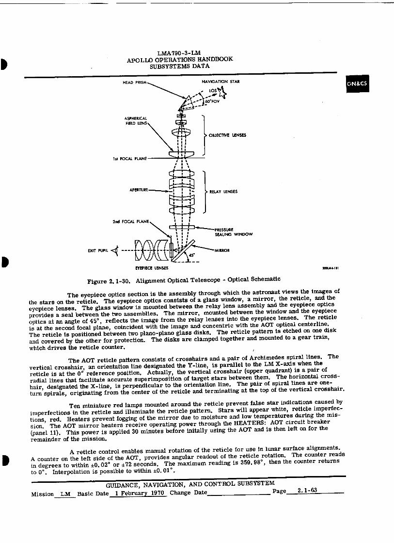
HEAD PRISM NAVIGATION STAR
ASPHERICAL FIELD LENS
1
I 8 I 1
1 1
} OBJECTIVE LENSES
1st FOCAL PLANE
LOS 1(4.
::)60°F0V
RELAY LENSES
2nd FOCAL PLANE
EXIT PUPIL <4 -
I 1 I I
L 4I-1"1----PRESSURE I g SEALING WINDOW g
1 i 1
r MIRROR
EYEPIECE LENSES 300044-181
I LMA 790-3- LM
APOLLO OPERATIONS HANDBOOK SUBSYSTEMS DATA
Figure 2.1-30. Alignment Optical Telescope - Optical Schematic
The eyepiece optics section is the assembly through which the astronaut views the images of the stars on the reticle. The eyepiece optics consists of a glass window, a mirror, the reticle, and the eyepiece lenses. The glass window is mounted between the relay lens assembly and the eyepiece optics provides a seal between the two assemblies. The mirror, mounted between the window and the eyepiece optics at an angle of 45 ° , reflects the image from the relay lenses into the eyepiece lenses. The reticle is at the second focal plane, coincident with the image and concentric with the AOT optical centerline. The reticle is positioned between two plano-plano glass disks. The reticle pattern is etched on one disk and covered by the other for protection. The disks are clamped together and mounted to a gear train, which drives the reticle counter.
The AOT reticle pattern consists of crosshairs and a pair of Archimedes spiral lines. The vertical crosshair, an orientation line designated the Y-line, is parallel to the LM X-axis when the reticle is at the 0 ° reference position. Actually, the vertical crosshair (upper quadrant) is a pair of radial lines that facilitate accurate superimposition of target stars between them. The horizontal cross-hair, designated the X-line, is perpendicular to the orientation line. The pair of spiral lines are one- turn spirals, originating from the center of the reticle and terminating at the top of the vertical crosshair.
Ten miniature red lamps mounted around the reticle prevent false star indications caused by imperfections in the reticle and illuminate the reticle pattern. Stars will appear white, reticle imperfec-tions, red. Heaters prevent fogging of the mirror due to moisture and low temperatures during the mis-sion. The AOT mirror heaters receive operating power through the HEATERS: AOT circuit breaker (panel 11). This power is applied 30 minutes before initally using the AOT and is then left on for the remainder of the mission.
A reticle control enables manual rotation of the reticle for use in lunar surface alignments. A counter on the left side of the AOT, provides angular readout of the reticle rotation. The counter reads in degrees to within ±0.02 ° or ±72 seconds. The maximum reading is 359.98 ° , then the counter returns to 0° . Interpolation is possible to within ±0.01 ° .
GUIDANCE, NAVIGATION, AND CONTROL SUBSYSTEM Mission LM Basic Date 1 February 1970 Change Date Page 2.1-63
GN&CS
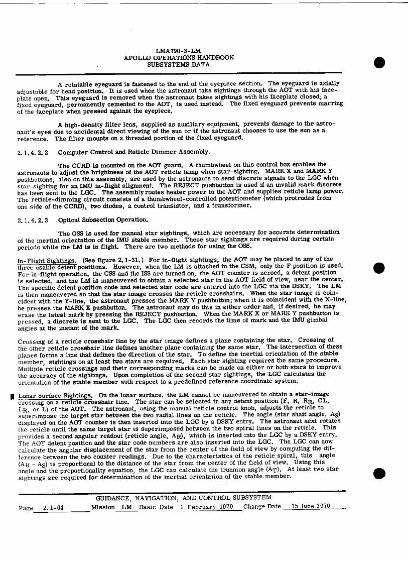
LMA790-3-LM APOLLO OPERATIONS HANDBOOK
SUBSYSTEMS DATA
A rotatable eyeguard is fastened to the end of the eyepiece section. The eyeguard is axially adjustable for head position. It is used when the astronaut taks sightings through the AOT with his face-plate open. This eyeguard is removed when the astronaut takes sightings with his faceplate closed; a fixed eyeguard, permanently cemented to the AOT, is used instead. The fixed eyeguard prevents marring of the faceplate when pressed against the eyepiece.
A high-density filter lens, supplied as auxiliary equipment, prevents damage to the astro-naut's eyes due to accidental direct viewing of the sun or if the astronaut chooses to use the sun as a reference. The filter mounts on a threaded portion of the fixed eyeguard.
2. 1.4. 2. 2 Computer Control and Reticle Dimmer Assembly.
The CCRD is mounted on the AOT guard. A thumbwheel on this control box enables the astronauts to adjust the brightness of the AOT reticle lamp when star-sighting. MARK X and MARK Y pushbuttons, also on this assembly, are used by the astronauts to send discrete signals to the LGC when star-sighting for an IMU in-flight alignment. The REJECT pushbutton is used if an invalid mark discrete has been sent to the LGC. The assembly routes heater power to the AOT and supplies reticle lamp power. The reticle-dimming circuit consists of a thumbwheel-controlled potentiometer (which protrudes from one side of the CCRD), two diodes, a control transistor, and a transformer.
2. I. 4. 2. 3 Optical Subsection Operation.
The OSS is used for manual star sightings, which are necessary for accurate determination of the inertial orientation of the IMU stable member. These star sightings are required during certain periods while the LM is in flight. There are two methods for using the OSS.
In-Flight Sightings. (See figure 2. 1-31.) For in-flight sightings, the AOT may be placed in any of the three usable detent positions, However, when the LM is attached to the CSM, only the F position is used. For in-flight operation, the CSS and the ISS are turned on, the AOT counter is zeroed, a detent position is selected, and the LM is maneuvered to obtain a selected star in the AOT field of view, near the center. The specific detent position code and selected star code are entered into the LGC via the DSKY. The LM is then maneuvered so that the star image crosses the reticle crosshairs. When the star image is coin- cident with the Y-line, the astronaut presses the MARK Y pushbutton; when it is coincident with the X-line, he presses the MARK X pushbutton. The astronaut may do this in either order and, if desired, he may erase the latest mark by pressing the REJECT pushbutton. When the MARK X or MARK Y pushbutton is pressed, a discrete is sent to the LGC. The LGC then records the time of mark and the IMU gimbal angles at the instant of the mark.
Crossing of a reticle crosshair line by the star image defines a plane containing the star. Crossing of the other reticle crosshair line defines another plane containing the same star. The intersection of these planes forms a line that defines the direction of the star. To define the inertial orientation of the stable member, sightings on at least two stars are required, Each star sighting requires the same procedure. Multiple reticle crossings and their corresponding marks can be made on either or both stars to improve the accuracy of the sightings. Upon completion of the second star sightings, the LGC calculates the orientation of the stable member with respect to a predefined reference coordinate system.
I Lunar Surface Sightings. On the lunar surface, the LM cannot be maneuvered to obtain a star-image crossing on a reticle crosshair line. The star can be selected in any detent position (F, R, RR, CL, LR, or L) of the AOT. The astronaut, using the manual reticle control knob, adjusts the reticle to superimpose the target star between the two radial lines on the reticle. The angle (star shaft angle, As) displayed on the AOT counter is then inserted into the LGC by a DSKY entry. The astronaut next rotates the reticle until the same target star is superimposed between the two spiral lines on the reticle. This provides a second angular readout (reticle angle, AR), which is inserted into the LGC by a DSKY entry. The AOT detent position and the star code numbers are also inserted into the LGC. The LGC can now calculate the angular displacement of the star from the center of the field of view by computing the dif-ference between the two counter readings. Due to the characteristics of the reticle spiral, this angle (AR - As) is proportional to the distance of the star from the center of the field of view. Using this angle and the proportionality equation, the LGC can calculate the trunnion angle (AT). At least two star sightings are required for determination of the inertial orientation of the stable member.
GUIDANCE, NAVIGATION, AND CONTROL SUBSYSTEM Page 2.1-64 Mission LM Basic Date 1 February 1970 Change Date 15 June 1970
•
•
•
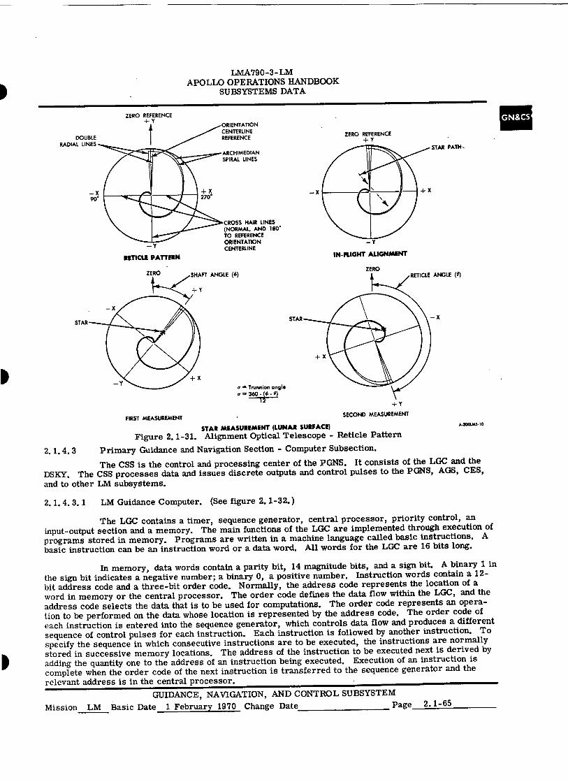
ORIENTATION CENTERLINE REFERENCE
ARCHIMEDIAN SPIRAL LINES
DOUBLE RADIAL LINES
-I- X 270°
-Y
RETICLE PATTERN
CROSS HAIR LINES (NORMAL, AND 180°
TO REFERENCE ORIENTATION CENTERLINE
STAR
= Trunnion angle 360 - (56 -
12
ZERO SHAFT ANGLE (<1.) ZERO
LMA790-3- LM APOLLO OPERATIONS HANDBOOK
SUBSYSTEMS DATA
ZERO REFERENCE +Y
ZERO REFERENCE 4-
_Y
1N-FLIGHT ALIGNMENT
STAR PATH--
+ Y
FIRST MEASUREMENT
SECOND MEASUREMENT
STAR MEASUREMENT (LUNAR SURFACE) A•3001JAS-10
Figure 2.1-31. Alignment Optical Telescope - Reticle Pattern
2.1.4.3 Primary Guidance and Navigation Section - Computer Subsection.
The CSS is the control and processing center of the PGNS. It consists of the LGC and the DSKY. The CSS processes data and issues discrete outputs and control pulses to the PGNS, AGS, CES, and to other LM subsystems.
2.1.4.3.1 LM Guidance Computer. (See figure 2.1-32. )
The LGC contains a timer, sequence generator, central processor, priority control, an input-output section and a memory. The main functions of the LGC are implemented through execution of programs stored in memory. Programs are written in a machine language called basic instructions. A basic instruction can be an instruction word or a data word. All words for the LGC are 16 bits long.
In memory, data words contain a parity bit, 14 magnitude bits, and a sign bit. A binary 1 in the sign bit indicates a negative number; a binary 0, a positive number. Instruction words contain a 12-bit address code and a three-bit order code. Normally, the address code represents the location of a word in memory or the central processor. The order code defines the data flow within the LGC, and the address code selects the data that is to be used for computations. The order code represents an opera-tion to be performed on the data whose location is represented by the address code. The order code of each instruction is entered into the sequence generator, which controls data flow and produces a different sequence of control pulses for each instruction. Each instruction is followed by another instruction. To specify the sequence in which consecutive instructions are to be executed, the instructions are normally stored in successive memory locations. The address of the instruction to be executed next is derived by adding the quantity one to the address of an instruction being executed. Execution of an instruction is complete when the order code of the next instruction is transferred to the sequence generator and the relevant address is in the central processor.
GUIDANCE, NAVIGATION, AND CONTROL SUBSYSTEM Mission LM Basic Date 1 February 1970 Change Date Page 2.1-65
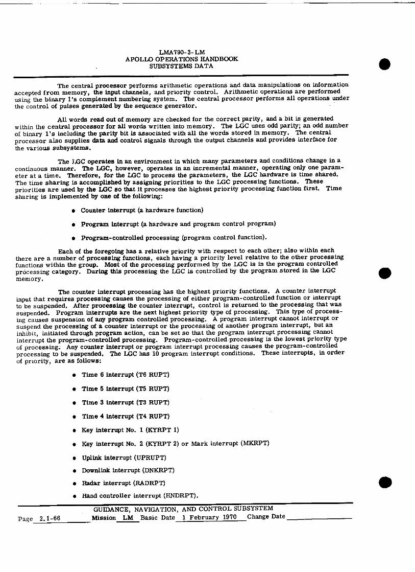
LMA790- 3- LM APOLLO OPERATIONS HANDBOOK
SUBSYSTEMS DATA
The central processor performs arithmetic operations and data manipulations on information accepted from memory, the input channels, and priority control. Arithmetic operations are performed using the binary l's complement numbering system. The central processor performs all operations under the control of pulses generated by the sequence generator.
All words read out of memory are checked for the correct parity, and a bit is generated within the central processor for all words written into memory. The LGC uses odd parity; an odd number of binary l's including the parity bit is associated with all the words stored in memory. The central processor also supplies data and control signals through the output channels and provides interface for the various subsystems.
The LGC operates in an environment in which many parameters and conditions change in a continuous manner. The LGC, however, operates in an incremental manner, operating only one param-eter at a time. Therefore, for the LGC to process the parameters, the LGC hardware is time shared. The time sharing is accomplished by assigning priorities to the LGC processing functions. These priorities are used by the LGC so that it processes the highest priority processing function first. Time sharing is implemented by one of the following:
• Counter interrupt (a hardware function)
• Program interrupt (a hardware and program control program)
• Program-controlled processing (program control function).
Each of the foregoing has a relative priority with respect to each other; also within each there are a number of processing functions, each having a priority level relative to the other processing functions within the group. Most of the processing performed by the LGC is in the program controlled processing category. During this processing the LGC is controlled by the program stored in the LGC memory.
The counter interrupt processing has the highest priority functions. A counter interrupt input that requires processing causes the processing of either program-controlled function or interrupt to be suspended. After processing the counter interrupt, control is returned to the processing that was suspended. Program interrupts are the next highest priority type of processing. This type of process-ing causes suspension of any program controlled processing. A program interrupt cannot interrupt or suspend the processing of a counter interrupt or the processing of another program interrupt, but an inhibit, initiated through program action, can be set so that the program interrupt processing cannot interrupt the program-controlled processing. Program-controlled processing is the lowest priority type of processing. Any counter interrupt or program interrupt processing causes the program-controlled processing to be suspended. The LGC has 10 program interrupt conditions. These interrupts, in order of priority, are as follows:
• Time 6 interrupt (T6 RUPT)
• Time 5 interrupt (T5 RUPT)
• Time 3 interrupt (T3 RUPT)
• Time 4 interrupt (T4 RUPT)
• Key interrupt No. 1 (KYRPT 1)
• Key interrupt No. 2 (ICYRPT 2) or Mark interrupt (MKRPT)
• Uplink interrupt (UPRUPT)
• Downlink interrupt (DNKRPT)
• Radar interrupt (RADRPT)
• Hand controller interrupt (HNDRPT).
GUIDANCE, NAVIGATION, AND CONTROL SUBSYSTEM Page 2.1 - 66 Mission LM Basic Date 1 February 1970 Change Date
•
•
•
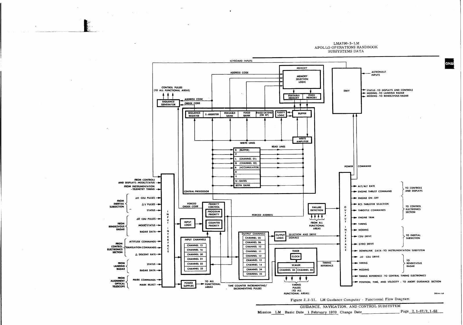
• B (BUFFER)
Z
▪ L (CHANNEL 01)
▪ CI (CHANNEL 02)
• A (ACCUMULATOR)
X
Y
U GATES
BOTH BANK
FORCED ADDRESS
OUTPUT CHANNELS
CHANNEL 05
CHANNEL 06
CHANNEL 10
CHANNEL 11 A DESCENT RATE—O.
STATUS --P.
RADAR DATA —110-
CHANNEL 30
CHANNEL 31
CHANNEL 32
CHANNEL 33
CHANNEL 12
CHANNEL 13
CHANNEL 14
CHANNEL 34
CHANNEL 35
- de CDU DRIVE
.—► TIMING
—•••• MODING
FROM LANDING
RADAR
TIMING REFERENCE SCALER I CHANNEL 04 CHANNEL 03
TO RENDEZVOUS RADAR
LMA790-3- LM APOLLO OPERATIONS HANDBOOK
SUBSYSTEMS DATA
KEYBOARD INPUTS
MEMORY
ADDRESS CODE
CONTROL PULSES (TO ALL FUNCTIONAL AREAS)
t
I SEQUENCE GENERATOR
A
MEMORY SELECTION
LOGIC
ERASABLE FIXED MEMORY MEMORY
ASTRONAUT INPUTS
"lb' STATUS - TO DISPLAYS AND CONTROLS MODING-TO LANDING RADAR MOOING - TO RENDEZVOUS RADAR
ADDRESS CODE
ORDER CODE
SEQUENCE REGISTER
S -REGISTER ERASABLE BANK
FIXED BANK
IXED EXTEND (CH 07)
PARITY LOGIC
BUFFER
WRITE
WRITE LINES AMPLIFIER
READ LINES
FROM CONTROLS AND DISPLAYS - MODE/STATUS
FROM INSTRUMENTATION - TELEMETRY TIMING —Br
CENTRAL PROCESSOR
• • • •
•
• •
PRIORITY CONTROL
PROGRAM PRIORITY
COUNTER PRIORITY
• • • • •
•
FAILURE DETECTION
FROM ALL FUNCTIONAL
AREAS
OUTPUT SELECTION AND DRIVE
LOGIC SIGNALS
TIMER
COMMAND
- ALT/ALT RATE
--••• ENGINE THRUST COMMAND
ENGINE ON • OFF
RCS THRUSTER SELECTION 0 U --16. THROTTLE COMMANDS
P U —116. ENGINE TRIM
T —116. TIMING
N
-
MODING
E
-
CDU DRIVE R F A —0. GYRO DRIVE C E
1 TO CONTROLS AND DISPLAYS
}
TO CONTROL ELECTRONICS SECTION
1 TO INERTIAL SUBSECTION
FORCED ORDER CODE
INPUT LOGIC
INPUT CHANNELS
CHANNEL 15
CHANNEL 16 —OP- DOWNLINK DATA-TO INSTRUMENTATION SUBSYSTEM
DSKY
POWER
FROM INERTIAL
SUBSECTION
FROM RENDEZVOUS
RADAR
FROM CONTROL
ELECTRONICS SECTION
AH CDU PULSES --1•P
A V PULSES —Ow
STATUS —40-
AH CDU PULSES-'—
MODr/STATUS —••••
RADAR DATA-0.
ATTITUDE COMMANDS;
RANSLATION COMMANDS —I•••
N P U
N
E R F A C E
FROM ALIGNMENT
OPTICAL TELESCOPE
MARK COMMANDS —110'
# —Ow TIMING REFERENCE - TO CENTRAL TIMING ELECTRONICS
POWER SUPPLIES
TO ALL FUNCTIONAL AREAS
MARK REJECT —N. TIME COUNTER INCREMENTING/
• DECREMENTING PULSES
TIMING PULSES
(TO ALL FUNCTIONAL AREAS)
- POSITION, TIME, AND VELOCITY - TO ABORT GUIDANCE SECTION
300I.M4- 168
Figure 2.2-51. LM Guidance Computer - Functional Flow Diagram
GUIDANCE. NAVIGATION, AND CONTROL SUBSYSTEM
Mission LM Basic Date 1 February 1970 Change Date Page 2.1-67/2.1-68
LMA790- 3 - LM APOLLO OPERATIONS HANDBOOK
SUBSYSTEMS DATA
The time 6, 5, 3, and 4 interrupt conditions are internal interrupts initiated by the LGC. The first key interrupt is initiated when a DSKY pushbutton is pressed. A mark signal, indicating a sighting, initiates the second key interrupt. The uplink interrupt indicates completion of an uplink word. The radar interrupt is generated when a complete radar work is received. As the ACA is moved out of detent the hand controller interrupt is initiated.
Before a priority program can be executed, the current program must be interrupted. The contents of the program counter and any intermediate results contained in the central processor should be preserved. The priority control produces an interrupt request signal, which is sent to the sequence generator. The signal, acting as an order code, executes as instruction that transfers the contents of the program counter and any intermediate results to memory. The interrupt request signal also transfers the priority program address from priority control to the central processor and, then, to memory through the write lines. As a result, the first basic instruction word of the priority program is entered into the central processor, from memory, and execution of the priority program begins. The last instruction of each priority program restores the LGC to normal operation, provided no other interrupt request is present, by transferring the previous contents of the program counter and intermediate results from their storage locations in memory back to the central processor.
Data pertaining to the flight, which include real time, acceleration, and IMU gimbal angles, are stored in memory locations called counters. The counters are updated as soon as new data becomes available. Data inputs to priority control are called incremental pulses. Each incremental pulse pro-duces a counter address and a priority request. The priority request signal is sent to the sequence generator as an order code. The control pulses produced by the sequence generator transfer the counter address to memory through the write lines of the central processor. The control pulses also enter the contents of the addressed counter into the central processor.
Real time, which is used in solving guidance and navigation problems, is maintained within the LGC, in the main time counter of memory. The main time counter provides a 745. 65-hour (approxi-mately 31 days) clock. Incremental pulses are produced in the timer and sent to priority control to increase the main time counter. The LGC clock is synchronized with ground elapsed time (GET) which is "time zero" at launch. The LGC time is transmitted once every second by downlink operation for com-parison with the GET of MSFN.
Incremental transmissions occur in the form of pulse bursts from the output channels to the CDU, the gyro fine alignment electronics, and the radars. The number of pulses and the time at which they occur are controlled by the LGC program. Discrete outputs originate in the output channels under program control. These outputs are sent to DSKY and other subsystems. A continuous pulse train at 1.024 me originates in the timing output logic and set as a synchronization signal to the timing elec-tronics assembly in the IS.
The uplink word from MSFN via the digital uplink assembly (DUA) is supplied as an incre-mental pulse to priority control. As this word is received, priority control produces the address of the uplink counter in memory and requests the sequence generator to execute the instructions that perform the serial-to-parallel conversion of the input word. When the conversion is completed, the parallel word is transferred to a storage location in memory by the uplink priority program.' The uplink priority program also retains the parallel word for subsequent downlink transmission. Another program converts the parallel word to a coded display format and transfers the display information to the DSKY.
The downlink operation of the LGC is asynchronous with respect to the IS. The IS supplies all the timing signals necessary for the downlink operation. (Refer to paragraph 2.1. 2 for interface discussion. )
Through the DSKY, the astronaut can load information into the LGC, retrieve and display information contained in the LGC, and initiate any program stored in memory. A key code is assigned to each keyboard pushbutton. When a DSKY pushbutton is pressed, the key code is produced and sent to an input channel of the LGC. A signal is also sent to priority control, where the signal produces the address of a priority program stored in memory and a priority request signal. The priority request signal is sent to the sequence generator. This results in an order code and initiates an instruction for interrupting the program in progress and for executing the key interrupt No. 1 priority program stored in memory. This program transfers the key code temporarily stored in an input channel, to the central
GUIDANCE, NAVIGATION, AND CONTROL SUBSYSTEM Mission LM Basic Date 1 February 1970 Change Date Page 2. 1-69
LMA790- 3- LM APOLLO OPERATIONS HANDBOOK
SUBSYSTEMS DATA
processor, where it is decoded and processed. A number of key codes are required to specify an address or a data word. The program initiated by a key code also converts the information from the DSKY key-board to a coded display format. The coded display format is transferred by another program to an output channel of the LGC and sent to the DSKY for display. The display is a visual indication that the key code was properly received, decoded, and processed by the LGC.
Timer. The timer generates the timing signals required for operation of the LGC. It is the primary source of timing signals for all subsystems.
The master clock frequency, generated by an oscillator, is applied to a clock divider logic circuit. The clock divider logic divides the master clock frequency into gating and timing pulses at the basic clock
■ rate of the LGC (1, 024 kpps). This basic clock rate is also applied to a scaler and a time pulse generator. The scaler further divides the output of the clock divider logic into pulses and signals which are used for gating, for generating rate signal outputs, and for accumulating time. The time pulse generator produces a recurring set of time pulses which define a specific memory cycle during which access to memory and data flow take place within the LGC.
Sequence Generator. The sequence generator executes the instructions stored in memory, processes instruction codes and produces control pulses that regulate data flow of the LGC. The control pulses control the operations assigned to each instruction and the data stored in memory.
The sequence generator consists of an order code processor, a command generator, and a control pulse generator. The sequence generator receives order code signals from the central processor and priority control. These signals are coded by the order code processor and supplied to the command generator. Another set of control pulses are used for gating the order code signals into the sequence generator at the end of each instruction. The command generator decodes the input signals and produces instruction commands which are supplied to the control pulse generator.
The control pulse generator receives 12 time pulses from the timer. These pulses occur in cycles and are used for producing control pulses in conjunction with the instruction commands. There are five types of control pulses: read, write, test, direct exchange, and special purpose. Information in the central processor is transferred from one register to another by the read, write, and direct exchange control pulses. The special purpose control pulses regulate the operation of the order code processor. The test control pulses are used within the control pulse generator. Branch test data from the central processor change the control pulse sequence of various functions.
Central Processor. The central processor performs all arithmetic operations required of the LGC, buffers all information coming from and going to memory, checks for correct parity on all words coming from memory, and generates a parity bit for all words written into memory. The central processor consists of flip-flop registers; write, clear, and read control logic; write amplifiers; a memory buffer register; a memory address register; a decoder; and parity logic.
Primarily, the central processor performs operations dictated by the basic instructions of the program stored in memory. Communication within the central processor is accomplished through write ampli-fiers. Data flow to or from memory to the registers, between individual registers, or into the central processor from external sources. Data are placed on the write lines and are routed to a specific register or to another part of the central processor under control of the write, clear, and read logic. This logic accepts control pulses from the sequence generator and generates signals to read the contents of a register onto the write lines and to write the contents into another register of the central processor or another area of the LGC. The particular memory location is specified by the contents of the memory address register. The address is fed from the write lines into this register, the output of which is decoded by the address decoder logic. Data are subsequently transferred from memory to the memory buffer register. The decoded address outputs are also used as gating functions within the LGC.
External inputs through the write amplifiers include the contents of the erasable and fixed memory bank registers, all interrupt addresses from priority control, control pulses associated with specific arithme-tic operations, and the start address for an initial start condition. Information from the input and output channels is placed on the write lines and routed to specific destinations within or external to, the central processor.
Page 2.1-70 GUIDANCE, NAVIGATION, AND CONTROL SUBSYSTEM
Mission LM Basic Date 1 February 1970 Change Date 15 June 1970
LMA 790-3- LM APOLLO OPERATIONS HANDBOOK
SUBSYSTEMS DATA
Priority Control. The priority control establishes a processing priority for operations that are performed by the LGC. Priority control is related to the sequence generator in that it controls the instructions to the LGC. The priority control processes input-output information and issues order code and instruction signals to the sequence generator and a 12-bit addresses to the central processor.
The priority control consists of start, interrupt, and counter instruction control circuits. The start instruction control circuit initializes the LGC if the program works itself into a trap, if a transient power failure occurs, or if the interrupt instruction control is not functioning properly. The LGC is initialized with the start order code signal, which not only commands the sequence generator to execute the start instruction, but resets other circuits. When the start order code signal is being used, issued, a stop signal is sent to the timer. This signal stops the time pulse generator until all essential circuits have been reset and the start instruction has been initiated by the sequence generator.
The interrupt instruction control forces execution of the interrupt instruction by sending the interrupt order code signal to the sequence generator, and the 12-bit address to the central processor. There are 10 addresses, each of which accounts for a particular function that is regulated by the interrupt instruc-tion control. The interrupt instruction control links the DSKY, telemetry, and time counters to the program. The interrupt addresses are transferred to the central processor by read control pulses from the sequence generator. The input-output circuits are the source of the Dm. , telemetry, and time counter inputs. The interrupt instruction control has a built-in priority chain which allows sequential control of the 10 interrupt addresses. The decoded addresses from the central processor control the priority operation.
The counter instruction control is similar to the interrupt instruction control in that it units input-output functions to the program. It also supplies 12-bit addresses to the central processor and instruction sig-nals to the sequence generator. The instruction signals cause a delay (not a interruption) in the program by forcing the sequence generator to execute a counter instruction. The addresses are transferred to the central processor by read control pulses. The counter instruction control also has a built-in priority of the 29 addresses it can supply to the central processor. The priority is also controlled by decoded counter address signals from the central processor. The counter instruction control contains an alarm detector, which produces an alarm if an incremental pulse is not processed properly.
Input-Output Interfaces. The input interface receives signals from the PGNS and other sources. (Refer to table 2. 1-3.) These signals are conditioned and isolated by the input interface before they are routed into the LGC logic circuitry. The output interface conditions and isolates the LGC output signals before routing them to their assigned destinations. The input and output circuits of the LGC include storage and gating devices, which are referred to as input-output channels.
Most input and output channels are flip-flop registers. Certain discrete inputs are applied to individual gatingcircuits, which are part of the input channel structure. Input data are applied directly to the input channels; there is no write process as in the central processor. However, the data are read out to the central processor under program control. The input logic circuits accept inputs that cause interrupt sequences within the LGC. These incremental inputs (acceleration data from the PIPA's, etc) are applied to the priority control circuits and, subsequently to associated counters in erasable memory.
Outputs from the LGC are placed in the output channels and are routed to specific systems through the output interface circuits. The operation is identical with that in the central processor. Data are written into an output channel from the write lines and read out to the interface circuits under program control. The downlink word is also loaded into an output channel and routed to the IS by the downlink circuits. The output timing logic gates synchronization pulses (fixed outputs) to the PGNS. These are continuous outputs, since the logic is specifically powered during normal operation of the LGC and during standby.
Channel No. 1. This channel is the L-register of the LGC.
Channel No. 2. This channel is the quotient (Q) register of the LGC.
Channel No. 3. This channel is the high-order scaler. The channel furnishes a 14-bit positive number whose least significant bit has a weight of 5.12 seconds. The maximum content of the register is 23.3 hours.
GUIDANCE, NAVIGATION, AND CONTROL SUBSYSTEM Mission LM Basic Date 1 February 1970 Change Date 15 June 1970 Page 2.1-71
LMA790-3- LM APOLLO OPERATIONS HANDBOOK
SUBSYSTEMS DATA
Channel No. 4. This channel is the low-order scaler. The channel furnishes a 14-bit positive number whose least significant bit has as a weight of 1/3200 second. The maximum content of the register is 5.12 seconds.
Channel No. 5 and 6. These output channels have eight bit positions and are associated with the RCS thrusters. The channel outputs are used for LM translation and rotation. The thruster com-mands from the channels are fed to preamplifiers of the jet drivers in the CES. The driver amplifier outputs are fed to the RCS to provide required control. The alphanumeric designation in the "bit position" columns indicates which of the 16 thrusters is controlled by that bit. A logic 1 in any of the bit positions causes the appropriate thruster to be fired.
Channel No. 7. The channel is the fixed, external memory register. It is associated with selection of word locations in the fixed memory. The channel has three bit positions.
. Channel No. 10. The information in this channel is routed to the DSKY, which illuminates the various electroluminescent displays associated with the DSKY.
Channel No. 11. All the information in this channel is routed to the DSKY condition indi-cators. If bit positions No. 1 through 7 contain a logic 1, the appropriate indicator goes on. Bit positions No. 13 and 14 contain the on-off commands for the ascent or descent engine (dependent on the setting of the ENG ARM switch).
Channel No. 12. This output chann4 contains the discrete commands that are used by the PGNS. Bit positions No. 13 and 14 contain the discretes issued to the radar section.
Channel No. 13. The first four bits of this channel are associated with the radars. The content of bit positions No. 1 through 3 defines which data are to be supplied by the radars to the LGC. (Refer to table 2. 1-4.) Bit position No. 4 contains the radar data strobe. When a "1" has been entered into bit position No. 4 simultaneously with the necessary selection bits in bit positions No. 1 through 3, the LGC starts to transmit one of the six control signals. While the control signal is being transmitted, a sync pulse is also transmitted. When the radar receives the sync pulses, it sends data pulses to the LGC. Bit positions No. 12 through 14 are program interrupt priority control commands. Bit position No. 6 is not used.
Channel No. 14. Bit positions No. 6 through 15 are associated with the ISS. CDU drive signals (bit positions No. 11 through 15) are generated when the bit position contains a logic 1. More than one of these signals can be generated simultaneously. Bit positions No. 7 and 8 select a gyro to be torqued positively or negatively and then applies a 3,200-cps signal to the appropriate gyro. The appropriate signal is determined by the configuration of bits No. 7 through 9. If bit positions No. 6 and 10 are a logic 1, a 3, 200-cps pulse train is routed to the gyro electronics specified by bit positions No. 7 through 9.
Channel No. 15. This input channel has five bit positions. Whenever a pushbutton on the DSKY is pressed, a five-bit code is entered into this channel.
Channel No. 16. This input channel has five bit positions. If a MARK pushbutton on the AOT is pressed, a logic 1 is entered into bit positions No. 3, 4, or 5. This initiates an interrupt routine within the LGC. Bits No. 6 and 7 receive discretes from the DES RATE switch (panel 5), commanding
I an increase or decrease in the rate of descent.
Channel No. 30. This input channel consists of 15 bit positions and uses inverted logic.
Bit position No. 1 informs the LGC that an abort, using the descent engine, has been commanded. This position is filled by either crewman pressing the ABORT pushbutton.
Bit position No. 2 informs the LGC that staging has occurred. This signal is generated in the Explosive Devices Subsystem.
Bit position No. 3 informs the LGC that the crew has armed the ascent or descent engine by setting the ENG ARM switch to the appropriate position.
Page 2.1-72 GUIDANCE, NAVIGATION, AND CONTROL SUBSYSTEM
Mission LM Basic Date 1 February 1970 Change Date 15 June 1970
•
•

LMA790-3- LM APOLLO OPERATIONS HANDBOOK
SUBSYSTEMS DATA
Table 2.1-3. LGC Input-Output Channel Assignments
cannel Name
Bit Positions
Channel 1 2 3 4 5 6. 7 8 9 10 11 12 13 14 15
rl 0
.1 0
1 ,J
.
L-register Q-register Scaler 2 Scaler 1
. ,
.-1 c4
cl
4d
■
5 Pitch Yaw
RCS B4U on
RCS A4D on
RCS A3U on •
RCS B3D on
RCS B2U on
RCS A2D on
RCS AlU on
RCS BID on
5
6 Roll RCS B3A on
RCS 334F on
RCS AIF on
RCS A2A on
RCS B2L on
RCS A3R on
RCS A4R on
RCS BlL on
7 F EXT register
FE 5 ,
FE 6 FE 7 7
10 DSKY Relay bit 1 Relay bit 2 VEL caution lamp
Relay bit 4 ALT caution lamp
Relay bit 6 Relay bit 7 Relay bit 8 Relay bit 9 Relay bit 10 Relay bit 11 Relay address 1
Relay address 2
Relay address 3
Relay address 4
10
11 DSKY ISS warning light (panel 1)
CMPTR ACTY lamp
. UPLINK ACTY status lamp
TEMP caution lamp
KEY REL status lamp
VERB/NOUN flash
OPR ERR status lamp
Test connect outbit
Test connect outbit
Caution reset
Engine-on command
Engine-off command
-I
11
12 GN&CS discretes
Zero RR CDU
RR error- counter enable
Horizontal vel low scale
Coarse-align enable
Zero IMU CDU
IMU error- counter enable
DID enable
+ Pitch trim - Pitch trim + Roll trim - Roll trim LR position command
RR auto track or enable
ISS turn-on complete
12
I' LGC discretes
Radar c (Refer
Radar b to table 2.1-4.)
Radar a Radar activity
Inhibit uplink
Block inlink Downlink word order
Enable RHC counter
RHC read
Test alarms
Enable standby
7
Reset trap
Reset trap
Reset trap
Enable T6 interrupt
13
14 IMU discretes
Outlink activity
Altitude rate
Altitude indicator
Thrust indicator drive
Gyro enable Gyro b Gyro a Gyro minus
Gyro activity
Shaft angle CDU drive
Trunnion angle CDU drive
8Z CDU drive
eyCDU drive
eXCDU drive 14
15 Main DSKY
Key 1 Key 2 Key 3 Key 4 Key 5 15
16 Navigation Mark X Mark Y Mark REJECT
Positive rate of descent
Negative rate of descent
16
30 GN&CS discretes
Abort Stage verify Engine armed
Abort Stage
Automaticthrottle
,_ DID RR CDU failure
IMU operate
G&N control of S&C
IMU cage IMU CDU failure
EMU failure MS turn-on request
Temperature in limits
30
31 Translation and rotation
+ Elevation (LPD)
- Elevation (LPD)
+ Yaw - Yaw + Azimuth (LPD)
- Azimuth (LPD)
+X-translation -X-translation +Y-translation -Y-translation +Z-translation -Z-translation Attitude hold Automatic stabilization
ACA out of detent
31
32 Impulse RCS A4D and A4R failed.
RCS A3U and A3R failed.
RCS B4U and B4F failed.
RCS B31) and B3A failed.
RCS BID and B1L failed.
RCS AlU and A1F failed.
RCS B2U and B2L failed.
RCS A2D and A2A failed.
Gimbal off Apparent gimbal fail
32
33 Optics (LGC)
RR power on automatic
RR range low scale
RR data good
LR data good
LR position No. 1
LR position No. 2
LR velocity data good
LR range low scale
Block uplink
Uplink too fast
Downlink too fast
PIPA failed.
LGC Oscillator alarm
33
34 Downlink 1 First of two words 34
35 Downlink 2 Second of two words 35
GUIDANCE, NAVIGATION, AND CONTROL SUBSYSTEM
Mission LM Basic Date 1 February 1970 Change Date Page 2.1-73/2.1-74

LMA790- 3- LM APOLLO OPERATIONS HANDBOOK
SUBSYSTEMS DATA
Bit position No. 4 informs the LGC that an abort, using the ascent engine, has been commanded.
Bit position No. 5 informs the LGC that it is in control of descent engine throttle.
Bit position No. 6 requests the LGC to supply forward and lateral velocity signals to the X-pointer indicators.
Bit position No. 7 contains a logic 1 when a failure has occurred in a radar CDU channel.
Bit position No. 9 contains a logic 1 when the IMU is in the operate mode.
Bit position No.
Bit position No.
Bit position No.
Bit position No. loop.
Bit position No. turned on.
10 informs the LGC that PGNS is in control of the LM.
11 indicates that the IMU cage condition exists in the ISS.
12 indicates that a failure has occurred in an inertial CDU channel.
13 indicates that a malfunction has occurred in the IMU stabilization
14 indicates that the ISS has been turned on or commanded to be
Bit position No. 15 indicates design limits.
that the stable member temperature has not exceeded its
Table 2.1-4. Channel 7 Radar Fixed Extension Bits
Function Bit 1 a
Bit 2 b
Bit 3 o
RR range rate 0 0 0
RR range 0 0 1
LR Vx 1 0 0
LR VY
1 0 1
LR Va 1 1 0
LR range 1 1 1
Channel No. 31. This input channel has 15 bit positions and uses inverted logic.
Bit positions No. 1 and 2 indicate positive and negative pitch manual input commands, respectively, from the ACA. These bits are used for elevation changes when the landing point designator (LPD) is used.
Bit positions No. 3 and 4 indicate positive and negative yaw manual input commands, respectively, from the ACA.
Bit positions No. 5 and 6 indicate positive and negative roll manual input commands, respectively, from the ACA. These bits are used for azimuth changes when the LPD is used.
GUIDANCE, NAVIGATION, AND CONTROL SUBSYSTEM Mission LM Basic Date 1 February 1970 Change Date Page 2.1-75
LIVIA790-3- LM APOLLO OPERATIONS HANDBOOK
SUBSYSTEMS DATA • Bit positions No. 7through 12 indicate positive and negative X-, Y-, and Z-translat_ commands from be TTCA. These signals command LM translation by on-and-off firing of the throsters, under LGC control.
Bit position J. 13 indicates that the C ES is operating in the attitude hold mode.
Bit position No. 14 indicates that the CES is operating in the automatic mode.
Bit position Ns. 15 informs that LGC that the ACA is out of detent.
Channel No. 32. ibis input channel has 15 bit positions and uses inverted logic.
Bit positions lb. I through 8 inform the LGC of a thruster pair shutoff, so that the LGC immedialek ceases to command the thruster pair on and compensates for its I(
Bit position lin- 9 hdorms the LGC that the descent engine pitch and roll gimbal dri -actuators have bib shut off by the astronaut.
Bit position No. le informs the LGC that the DECA has detected an apparent failure the pitch or Mitzi& loop.
Channel No. 33. This input channel has 15 bit positions and uses inverted logic.
Bit position No. 2 bdicates that RR power is on and the RR mode selector switch (panel 3) is set be UGC.
Bit position No. 3 adicates that the RR scale factor is on Iow scale. This signal is implemented notomatically by the RR at a range of less than 50 nautical miles.
Bit positions No. 4 and 5 indicate that the RR and LR range trackers have lock..
Bit positions Na. Sand 7 indicate the position of the LR antenna.
Bit position lb. S indicates that the LR velocity trackers have locked on.
Bit position No. 9 indicates that the LR scale factor is on low scale. This signal is implemented by be LR at approximately 2,500 feet.
-Bit position lb. i is used to inhibit reception of data via uplink. This signal is ■ always in the logic 0 state.
Bit positions No. 11 and 12 indicate that PGNS telemetry rate is too high.
Bit position No. 13 Indicates failure in an accelerometer loop.
Bit position No. 14 indicates an LGC internal malfunction.
Bit position lb. 15 indicates that the LGC oscillator stopped.
Channels 34 and M. These outputs channels provide 16-bit words, including a parity bit, for downlink telemetry transmission.
Memory. Memory provides the shwage capability for the LGC; it is divided into two sections: erasab . meme 77-n -ym and fixed memory. The namable memory has a storage capacity of 2,048 words; the fixed memory, 36,864 words. The erasable memory is a random-access, destructive-readout storage devil Data stored in the erasable memory an be altered or updated. The fixed memory is a nondestructive storage device. Data stored in the hoed memory are unalterable, because the data are hardwired and readout is nondestructive.
Both memories contain magnetic-core storage elements. In the erasable memory, the storage elemen form a core array; in the fixed memory, the storage elements form three core ropes. The eras memory has a density of one word pee- 16 cores; the fixed memory, eight words per core. Each is located by an address.
GUIDANCE, NAVIGATION, AND CONTROL SUBSYSTEM Page 2.1-76 Mission LIE Basic Date 1 February 1970 Change Date 15 June "
LMA790-3- LM APOLLO OPERATIONS HANDBOOK
SUBSYSTEMS DATA
GN&CS In the fixed memory, addresses are assigned to instruction words to specify the sequence in which they are to be executed; blocks of addresses are reserved for data, such as constants and tables. Information is placed into the fixed memory permanently by weaving patterns through the magnetic cores. Informa-tion is written into assigned locations in the erasable memory with the DSKY, uplink, or program operation.
Both memories use a common address register (S-register) and an address decoder in the central proc-essor. When the S-register contains an address pertaining to the erasable memory, the erasable memory cycle timing is energized. Pulses sent to the erasable memory cycle timing then produce strobe signals for the read, write, and sense functions. The erasable memory selection logic receives an address and a decoded address from the central processor and produces selection signals, which permit data to be written into, or read out from, a selected storage location. When a word is read out from a storage location in the erasable memory, the location is cleared. A word written into the erasable memory, through the memory buffer register in the central processor, by a write strobe operation. A word read from a storage location is applied to the amplifiers. The amplifiers are strobed and the information is entered into a buffer register of the central processor. The memory buffer register re-ceives information from both memories.
The address in the 5-register energizes the fixed memory cycle timing when a location in the fixed memory is addressed. Pulses sent to the fixed memory cycle timing produce the strobe signals for the read and sense functions. The selection logic receives an address from the write lines and a decoded address from the S-register, and produces selection signals for the core rope. The content of a storage location in the fixed memory is strobed from the fixed memory sense amplifiers to the erasable memory sense amplifiers and then entered into the memory buffer register of the central processor.
Alarm-Detection Network. The alarm-detection network consists of temperature, voltage, scaler, double frequency scaler oscillator, memory clamping, and the warning filter and integrator circuits. The alarm-detection network monitors LGC operation. If an LGC failure is detected, a failure signal is routed to the DSKY for display. An LGC power failure is also displayed by the LGC warning light (panel 1).
2.1.4.3.2 Display and Keyboard Assembly. (See figure 2. 1-33.)
The DSKY consists of a keyboard, display panel, condition indicators, and a relay package. The keyboard enables the astronauts to insert data into the LGC and to initiate LGC operations. Through the keyboard, the astronauts can also control ISS moding. The DSKY display panel provides visual indi-cations of data being loaded into the LGC, LGC condition, and LGC program. The display panel also provides the LGC with a means of displaying or requesting data. The condition indicators display PGNS status and malfunctions. The controls and displays associated with the DSKY are discussed in section 3.
Keyboard. The DSKY keyboard is used to insert or read out LGC data. The keyboard consists of 10 numerical pushbuttons (0 to 9), two sign pushbuttons (+ and -), and seven instruction pushbuttons (ENTR, CLR, VERB, NOUN, RSET, PRO, and KEY REL). All the pushbuttons, except the PRO pushbutton, have five-bit codes associated with them; they convey information to the LGC. The PRO pushbutton is hardwired into the LGC power supplies.
Displays and Indicators. There are two types of displays on the DSKY: control displays and data displays. Each display can display any decimal character or remain blank. The indicators on the DSKY are re-ferred to as condition lights; they represent various PGNS operating conditions. Each control display (VERB, NOUN, and PROG) can display two decimal characters or remain blank. The VERB and NOUN displays can also flash. The data displays are three separate registers, referred to as R1, R2, and R3. Each register can display as many as five decimal characters, with or without a plus or minus sign, or remain blank. Each of the 11 condition lights on the DSKY is labeled with the PGNS condition it repre-sents; it goes on if that condition occurs. The condition lights and the conditions they represent are described in section 3.
GUIDANCE, NAVIGATION, AND CONTROL SUBSYSTEM
Mission LM Basic Date 1 February 1970 Change Date Page 2.1-77
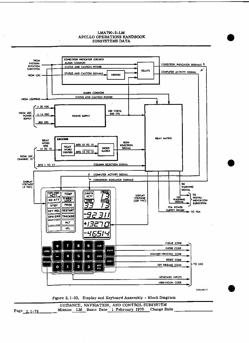
TEMP UPLINK I AGTY
NO ATT [4.11M. STBY
KEY REL
OPR ERR
PROG
RESTART
TRACKER
n J
CMPTR AC TY
PRO
ENTER CODE
STANDBY/PROCEED CODE
KEY REL
TO LGC
RESET CODE
KEY RELEASE CODE
• RELAYS
DRIVERS
FROM INSTRUM-
ENTATION SUBSYSTEM
FROM LGC
CONDITION INDICATOR CIRCUITS
ALARM COMMON
STATUS AND CAUTION POWER
STATUS AND CAUTION SIGNALS
CONDITION INDICATOR SIGNALS r•
COMPUTER ACTIVITY SIGNAL
LMA790-3-LM APOLLO OPERATIONS HANDBOOK
SUBSYSTEMS DATA
ALARM COMMON
•
CLEAR CODE
,I••■•••••,,
NOUN
0
FROM LIGHTING
FROM LGC POWER SUPPLY
+ 28 VDC
+ 14 VDC
800 CPS
FROM LGC CHANNEL 10
DISPLAY VOLTAGE (S VDC)
RELAY WORD
BITS 12 TO 15
BITS 1 TO 11
ALT
I VEL
•
..1 COMPUTER ACTIVITY SIGNAL
44' CONDITION INDICATOR SIGNALS
VERB )
I .7_1
-9 2 3 + 13E7 El
Lbssi
RELAY MATRIX
STATUS AND CAUTION POWER
250 VOLTS, 800 CPS
POWER SUPPLY
DECODER
BITS 12 TO 15 DIODE
MATRIX
ROW SELECTION
SIGNAL RELAY WORD
DRIVERS BITS 12 TO 15
COLUMN SELECTION SIGNAL
LOG WARNING
SIGNAL
PTA POWER SUPPLY INHIBIT
ISS WARNING SIGNAL
TO INSTRU• MENTATION SUBSYSTEM
11A. TO PSA
DISPLAY VOLTAGE (250 VAC)
LMA790-3-LM APOLLO OPERATIONS HANDBOOK
SUBSYSTEMS DATA
Relay Package. The relay package consists of a relay matrix and decoding circuits,
GN&CS
The inputs entered from the keyboard, as well as other information, appear on the displays after proc-essing by a program. Display of information is accomplished through the relay matrix. A unique code for the characters to be displayed is formed by 15 bits from output channel No. 10 in the LGC. Bits No. 12 through 15 are decoded by the decoding circuits and, along with bits No. 1 through 11, energize specific relays in the matrix, causing appropriate characters to be illuminated. The information dis-played is the result of a key code punched in by the astronaut, or is LGC-controlled information. The display characters are formed by electroluminescent segments, which are energized by a voltage from the power supply, routed through relay contacts. Specific inputs from the PGNS are also applied, through the LGC, to certain relays in the matrix through output channel No. 10 of the LGC. The re-sulting relay-controlled outputs are caution signals to the PGNS.
2. 1. 4, 3. 3 Manual Operation of DSKY.
The operator of the DSKY can communicate with the LGC by pressing a sequence of push-buttons on the DSKY keyboard. Except for the PRO pushbutton, each pushbutton pressed inserts a five-bit code into the LGC. The LGC responds by returning a code, which controls a display on the display panel, to the DSKY or by initiating an operation by the central processor. The LGC can also initiate a display of information or request the operator for some action, through the processing of its program,
The basic language of communication between the operator and the DSKY consists of verb and noun codes. (Refer to Apollo Operations Handbook, Volume II, paragraph 4. 4 for DSKY verb and noun codes.) The verb code indicates what action is to be taken (operation). The noun code indicates to what this action is applied (operand). Verb and noun codes may be originated manually or by internal LGC sequence. Each verb or noun code contains two numerals. The standard procedure for manual operation involves pressing a sequence of seven pushbuttons:
VERB V1 V2 NOUN NI N2 ENTR
Pressing the VERB pushbutton blanks the VERB code display on the display panel and clears the verb code register within the LGC. The next two pushbuttons (0 to 9) pressed provide the verb code (V1 and V2). Each numeral of the code is displayed by the VERB display as the pushbutton is pressed. The NOUN pushbutton operates the same as the VERB pushbutton, for the NOUN display and noun code register. Pressing the ENTR pushbutton starts the operation called for by the displayed verb-noun combination. It is not necessary to follow any order in punching in the verb or noun code. It can be done in reverse order, and a previously entered verb or noun may be used without repunching it.
If an error in the verb code or the noun code is noticed before the ENTR pushbutton is pressed, correctionis made by pressing the VERB or NOUN pushbutton and repunching the erroneous code, without changing the other one. Only when the operator has verified that the desired verb and noun codes are displayed should he press the ENTR pushbutton. An example of the sequence in which the pushbuttons are pressed is as follows: VERB, 1, 6, NOUN, 2, 1, ENTR. Pressing the ENTR pushbutton advises the LGC that it should perform the operation called for by the verb and noun codes. An alternative sequence would be: NOUN, 2, 1, VERB, 1, 6, ENTR. When the VERB pushbutton is pressed, the two VERB displays are blanked. As the digits of the VERB code are punched in, they are displayed in the VERB displays. The NOUN display operates in the same manner.
A noun code can refer to a group of LGC erasable registers, a group of counter registers, or it may serve merely as a label. A label noun does not refer to a particular LGC register; it conveys informa-tion by its noun code number only. The group of registers to which a noun code refers may be a group of one, two, or three members. These members are generally referred to as 1-, 2-, or 3-component nouns. The component is understood to be a component member of the register group to which the noun refers. The machine addresses for the registers to which a noun refers are stored in the LGC in noun tables.
A single noun code refers to a group of 1-, 2-, or 3-component members. The verb code deter-mines which component member of the noun group is processed. For instance, there are five differentload verbs. Verb 21 is required for loading the first component of whatever noun is used therewith; verb 22 loads the second component of the noun; verb 23, the third component; verb 24, the first and second com-ponent; and verb 25, all three components. A similar component format is used for the display and monitor verbs.
GUIDANCE, NAVIGATION, AND CONTROL SUBSYSTEM
Mission LM Basic Date 1 February 1970 Change Date 15 June 1970 Page 2.1-79
LMA790-3- LM APOLLO OPERATIONS HANDBOOK
SUBSYSTEMS DATA
When the decimal display verb is used, all the component members of the noun being used are scaled as appropriate, converted to decimal, and displayed in the data display registers. Decimal data are identified by a plus or minus sign preceding the five digits. If a decimal format is used for load-ing data of any component members of a multicomponent load verb, it must be used for all components of the verb. Mixing of decimal and octal data for different components of the same load verb is not permis-sible. If data are mixed, the OPR ERR condition light goes on.
Monitor verbs update displayed data once a second. Once a monitor -verb is executed, the data on the display panel continues to be updated until the monitor is turned off by V33E (proceed/ proceed without data), V34E (terminate), and internal program initiation of the program, or by a fresh start of the LGC. V33E is the abbreviation for the sequence of depressions (VERB, 3, 3, ENTR) that instructs the LGC to stop updating the monitor (display registers),
After any use of the DSKY, the numerals (verb, noun, and data words) remain visible until the next use of the DSKY. If a particular use of the DSKY involves fewer than three data words, the data display registers (R1, R2, R3) not used remain unchanged unless blanked by deliberate program action.
"Machine address to be specified" nouns allow any machine address to be used. When the ENTR pushbutton is pressed the verb-noun combination senses a noun of this type, and the flash is immediately turned on. The verb code is left unchanged. The operator loads the desired five-octal-character complete machine address. It is displayed in R3 as it is punched in. If an error is made in loading the address, the clear (CLR) pushbutton may be used to remove it.
Data LoadinE. Some verb-noun codes require additional data to be loaded. If additional data are required after the ENTR pushbutton is pressed, following the keying of the verb-noun codes, the VERB and NOUN displays flash on and off at a 1. 5-cps rate. These displays continue to flash until all information asso-ciated with the verb-noun code is loaded.
Numerical data are considered decimal if the five-numeral data word is preceded by a plus sign or a minus sign: if no sign is supplied, it is considered octal. The + and - pushbuttons are accepted by the LGC only when they precede the first numeral of the data word; they are ignored at any other time. Decimal data must be loaded in full five-numeral words (no zeros may be suppressed): octal data may be loaded with high-order zeros suppressed. If decimal format is used for any component of a multicomponent load verb, it must be used for all components of that verb. Mixing of octal and decimal data for different components of the same load verb is not permissible. (If such data are mixed, the operator error alarm is initiated.) The ENTR pushbutton must be pressed after each data word. This tells the program in progress that the numerical word entered is complete.
After the ENTR pushbutton is pressed, the VERB and NOUN displays stop flashing and remain on, dis-playing the entered verb-noun combination. As the various pushbuttons are pressed (while entering the data), the digits are displayed in positions of one of the display registers corresponding to the order in which they were entered. As the data is entered, it is temporarily stored in intermediate buffers. It is not placed into its final destination as a specified address noun code until the final ENTR pushbutton is pressed.
If an attempt is made to enter more than five numerals in sequence, the sixth and subsequent numerals are rejected. If the 8 or 9 pushbutton is pressed during octal load (as identified by lack of a sign entry), it is rejected and the operator error (OPR ERR) condition light goes on.
In multicomponent load situations, the appropriate single component load verbs are flashed one at a time. The LGC always instructs the operator through a loading sequence. The operator (or the internal pro-gram) initiates the sequence by selecting VERB, 25 (load 3 components of), (any noun will do), ENTR. The verb code is changed to 21 (load first component of) and the flash is turned on. Verb 21 continues to be flashed as the first data word is being loaded. When the ENTR pushbutton is pressed, the verb code is changed to 22 (load second component). Flashing continues while the second data word is loaded. When the ENTR pushbutton is pressed, the verb code is changed to 23 (load third component); the flash continues while the third data word is loaded. When the ENTR pushbutton is pressed, the flash is turned off and all three data words are placed in the locations specified by the noun.
GUIDANCE, NAVIGATION, AND CONTROL SUBSYSTEM Page 2.1-80 Mission LM Basic Date 1 February 1970 Change Date 15 June 1970
•
•
•
LMA790 -3 -LM APOLLO OPERATIONS HANDBOOK
SUBSYSTEMS DATA
Correcting Erroneous Data. The CLR pushbutton is used to remove errors in R1, R2, or R3 during data loading. This allows the astronaut to begin loading again. Use of the CLR pushbutton does not affect the PROG, NOUN, or VERB displays.
To correct errors for single-component load verbs, the CLR pushbutton clears the register being loaded, provided that the CLR pushbutton is pressed before the ENTR pushbutton. Once the ENTR pushbutton is pressed, the CLR pushbutton has no effect. After the ENTR pushbutton has been pressed, the only way to correct an error for a single component is to begin to load again.
To correct errors for second and third component load verbs, the CLR pushbutton is used. The first pressing of the CLR pushbutton clears the register being loaded. Consecutive pressing clears the regis-ters above the register being loaded, until R1 is cleared.
Program'Selection. Verb 37 is used to change the program. Keying VERB, 37, and ENTR blanks the NOUN display; the verb code flashes. The two-digit program code is then loaded. For verification pur-poses, the program code is displayed, as it is loaded, in the NOUN display register. When the ENTR pushbutton is pressed, the flashing stops, the new program to be entered is requested, and a new program code is displayed in the PROG display.
Release of Display and Keyboard System. The display and keyboard system program can be used by in-ternal LGC programs. However, any operator keyboard action (except reset) makes the system program unavailable (busy) to internal routines. The operator has control of the system until he wishes to release it. Thus, he is assured that data he wishes to observe will not be replaced by internally initiated data displays. In general, it is recommended that the operator release the system for internal use when he has temporarily finished with it. This is done by pressing the KEY RE L pushbutton.
If an internal program attempts to use the system, but finds that the operator has used it and not yet re-leased it, the KEY REL light goes on. When the operator finds it convenient, he should press the KEY RE L pushbutton to allow the internal program to use the display and keyboard panel.
Operator Error. The OPR ERR condition light goes on when the operator presses pushbuttons improperly. The light goes on when an undefined verb or noun is entered or when a verb that is defined and a noun that is defined are entered, but the combination of verb and noun is illegal. Both of these errors do not re-quire any further operator action. The following operator errors also do not require further action:
• The component number of the verb exceeds the number of the components in the noun.
• The octal display and monitor verbs are used with a "decimal only" noun.
• The decimal display and monitor verbs are used with mixed nouns.
• The decimal display and monitor verbs are used with an "octal only" noun.
• A no-load verb is used with a noun that is not a no-load noun. (Nouns that have a split minute/second scale for any component are no-load nouns. )
a An input code other than those that are defined is received from the keyboard.
• The contents of the register exceed its limit.
When improper data are entered for a defined verb-noun combination that requires loading of additional data, the OPR ERR condition light goes on. The error is detected when the final entry of the loading sequence is made. When the light goes on, recycling to the beginning of the loading sequence is required. Only the data must be entered again, not the verb-noun combination. Other errors that cause the OPR ERR condition light to go on, and require recycling, are as follows:
• The address entered for a "machine address to be specified" noun is not octal.
GUIDANCE, NAVIGATION, AND CONTROL SUBSYSTEM Mission LM Basic Date 1 February 1970 Change Date Page 2. 1 - 81
GN&C5
LMA790-3-LM APOLLO OPERATIONS HANDBOOK
SUBSYSTEMS DATA
• Octal and decimal data are mixed in multicomponent load verbs. (All data words loaded for a given noun must be all octal or all decimal.)
• Octal data are loaded a "decimal only" noun.
• Decimal data are loaded an "octal only" noun.
• Loaded decimal data numerically exceed the maximum permitted by the scale factor associated with the appropriate component of the noun.
• Negative decimal data are loaded, using the Y-optics scale.
• For displays of time, the three data words are not loaded for the hours, minutes, and seconds scale.
• When loading with the hours, minutes, and seconds scale, the minutes exceed 59, the seconds exceed 59.99, and the total exceeds 745 hours 39 minutes 14.55 seconds.
• Two numerals are not supplied for the program code under verb 37.
2.1.4.3.4 DSKY Operation Under LGC Control.
The principles of DSKY operation by the internal LGC sequences are the same as those de-scribed for manual operation of the DSKY. DSKY operation by the internal LGC sequences encompasses the following categories: display, loading, please perform, and please mark.
The display operation is used to display data to the operator. Data computed by the mission program can be displayed by using various display verbs. The loading operation requests that the operator load data. The please-perform operation requests an action by the operator, who then notifies the LGC that he has complied. The please-mark operation requests that the operator press MARK pushbutton on the AOT for an optics sighting.
LGC-initiated verb-noun combinations are displayed as static or flashing displays. A static display identifies data displayed only for operator information; no operator response is required. If the dis-played verb-noun combination flashes, appropriate operator response is required, as dictated by the verb-noun combination. In this case, the internal sequence is interrupted until the operator responds appropriately, then the flashing stops and the internal sequence resumes. A flashing verb-noun display must receive only one of the proper responses; otherwise, the internal sequence that instructed the display may not resume.
Display. The appropriate operator response to a flashing display (verb-noun combination) is as follows:
• Correct the data and perform the appropriate load-verb sequence. Upon pressing the ENTR pushbutton, the internal sequence proceeds normally.
• Recycle by keying VERB, 32, ENTR. This returns the program to a previous location.
• proceed, or proceed without data, by pressing the PRO pushbutton. This indi-cates acceptance of the displayed data and a desire for the internal sequence to continue normally.
• Terminate by keying VERB, 34, ENTR.
Data Loading. When data are to be loaded, the VERB and NOUN displays flash. The flashing occurs whether data loading is initiated by LGC or by the operator. The appropriate register (R1, R2, or R3) is blanked in anticipation of data loading. Data are loaded as five-numeral words; they are displayed numeral-by-numeral in one of the registers as loaded.
Page 2.1 - 82
GUIDANCE, NAVIGATION, AND CONTROL SUBSYSTEM Mission LM Basic Date 1 February 1970 Change Date 15 June 1970
•
•
LMA790 -3 -LM APOLLO OPERATIONS HANDBOOK
SUBSYSTEMS DATA
The appropriate response to an internally initiated verb-noun combination for loading is as follows:
• Load the desired data. After the final entry, the internal sequence proceeds normally.
• Proceed, or proceed without data, by pressing the PRO pushbutton.
• Terminate by keying VERB, 34, ENTR,
Please Perform. The operator must respond to a "please perform" request. Withthis request, the verb-noun combination flashes and the internal sequence is interrupted. The "please perform"verb (50) is usually used with the "checklist" noun (25) and an appropriate checklist code number in Rl. (Refer to Apollo Operations I Handbook, Volume II, paragraph 4.4 for checklist codes.) The appropriate response is as follows:
• Press the ENTR pushbutton to indicate that the requested action has been performed. (The internal sequence continues normally.) Proceed without data by pressing the PRO pushbutton. The operator chooses not to perform the requested action, but desires the internal sequence to continue with the previous data.
• Terminate by keying VERB, 34, ENTR.
The "please perform" verb is also used with the "change of program" noun and "engine-on enable" noun. Its use in these cases is subject to the LGC program in process.
Please Mark. The "please mark" verbs are flashed when the LGC is prepared to accept optical-sighting data from the AOT.
2. 1. 4. 3.5 Primary Guidance and Navigation Section - Modes of Operation.
The PGNS is considered to be in an operational mode upon initiation of a program by the astronauts or MSFN. When operating under one of the various programs, the LGC automatically computes required mission parameters, commands the PGNS and the other sections and subsystems, and displays pertinent data to the astro- naut and MSFN (via downlink). (Refer to Apollo Operations Handbook, Volume II, paragraph 4.4 for PGNS pro- I grams. ) For operational compatibility, the astronauts and/or MSFN can initiate, modify, or interrupt the automatic program sequences. In certain cases, the programs are initiated by a previous program.
The LGC is preptogrammed to display a mode number or program number on the DSKY in response to initiation of a program. This display remains on until the sequence of events for the specific mission phase, as dictated by the program, is completed.
The astronaut may also be required, or may wish, to perform specific submodes (routines) during a program. The PGNS routines are used by most LGC programs, to perform the required input and output functions. (Refer to Apollo Operations Handbook, Volume II, paragraph 4.4 for PGNS routines.) Through these routines, the LGC can command various guidance modes, display and accept information from the DSKY and radar, provide for telemetry inputs and outputs, control positioning of the RR antenna and the IMU stable member, and remain cognizant of the PGNS and LM subsystem operations. Only the ISS of the PGNS operates under specific modes when the PGNS is used. These modes of ISS operation are listed and defined in paragraph 2.1. 4.1. 8.
2. 1. 4. 4 Abort Guidance Section.
2. I. 4. 4. 1. Abort Sensor Assembly. (See figure 2. 1-34. )
The ASA contains three floated, pulse-rebalanced, single-degree-of-freedom, rate-integrating gyroscopes and three pendulous reference accelerometers in a strapped-down configuration. These six sensors are housed in a beryllium block, which is mounted on the navigation base. The sen-sors are aligned with the three LM reference axes. The assembly also includes pulse torque servo-amplifiers (one associated with each sensor), a frequency divider, temperature control amplifiers, and a power supply.
GUIDANCE, NAVIGATION, AND CONTROL SUBSYSTEM
Mission LM Basic Date 1 February 1970 Change Date 15 June 1970 Page 2.1-83
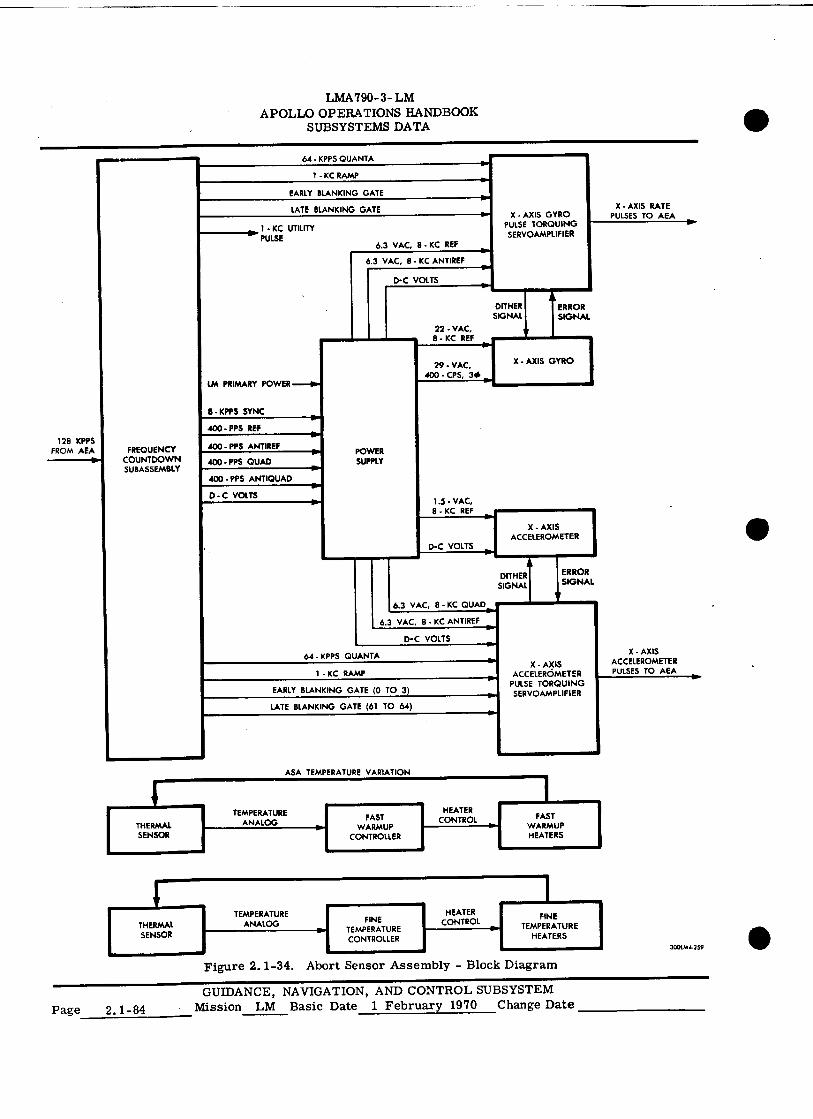
TEMPERATURE ANALOG THERMAL
SENSOR
DITHER SIGNAL
ERROR SIGNAL
X - AXIS GYRO
8 - KPPS SYNC
• PPS REF
LM PRIMARY POWER---F
FAST WARMUP
CONTROLLER
HEATER CONTROL
64 - KPPS QUANTA
1- KC RAMP
EARLY BLANKING GATE
X - AXIS GYRO PULSE TORQUING SERVOAMPLIFIER
X • AXIS RATE PULSES TO AEA
1 • KC UTILITY PULSE
LATE BLANKING GATE
6.3 VAC, B KC REF
3 VAC, 8 KC ANTIREF
D•C VOLTS
128 KPPS FROM AEA FREQUENCY
COUNTDOWN SUBASSEMBLY
POWER SUPPLY PPS QUAD
400 - PPS ANTIREF
S ANTIQUAD
C VOLTS 1.5 - VAC,
8 - KC REF
X - AXIS ACCELEROMETER
D-C VOLTS
DITHER SIGNAL
6.3 VAC, 8 - KC QUAD
6.3 VAC. 8 - KC ANTIREF
D-C VOLTS
ERROR SIGNAL
64 - KPPS QUANTA
1 - KC RAMP
EARLY BLANKING GATE (0 TO 3)
LATE BLANKING GATE (61 TO 64)
X - AXIS ACCELEROMETER
PULSE TORQUING SERVOAMPLIFIER
0.•
X • AXIS ACCELEROMETER PULSES TO MA
22 - VAC, 8 KC REF
29 • VAC, 400 • CPS, 3# •
ASA TEMPERATURE VARIATION
fAST WARMUP HEATERS
TEMPERATURE ANALOG
HEATER CONTROL
LMA 790-3- LM APOLLO OPERATIONS HANDBOOK
SUBSYSTEMS DATA
1
L FINE TEMPERATURE
HEATERS
0.. I 3..,2"
•
Figure 2.1-34. Abort Sensor Assembly - Block Diagram
Page 2.1-84 GUIDANCE, NAVIGATION, AND CONTROL SUBSYSTEM
Mission LM Basic Date 1 February 1970 Change Date


![inertial navigation[persian]](https://img.pdfslide.net/doc/110x75/55cf8f81550346703b9d0bdb/inertial-navigationpersian.jpg)