Embed Size (px)
Citation preview
2014 International Conference on Indoor Positioning and Indoor Navigation, 27th-30th October 2014
Foot-mounted inertial navigation made easyJohn-Olof Nilsson1, Amit K Gupta2, and Peter Handel1
1Dept. Signal Processing, KTH Royal Institute of Technology, Stockholm, Sweden2GT Silicon Pvt Ltd, Kanpur, India
Abstract—Despite being around for almost two decades, foot-mounted inertial navigation only has gotten a limited spread.Contributing factors to this are lack of suitable hardwareplatforms and difficult system integration. As a solution to this,we present an open-source wireless foot-mounted inertial navi-gation module with an intuitive and significantly simplified deadreckoning interface. The interface is motivated from statisticalproperties of the underlying aided inertial navigation and arguedto give negligible information loss. The module consists of botha hardware platform and embedded software. Details of theplatform and the software are described, and a summarizingdescription of how to reproduce the module are given. Systemintegration of the module is outlined and finally, we provide abasic performance assessment of the module. In summary, themodule provides a modularization of the foot-mounted inertialnavigation and makes the technology significantly easier to use.
I. INTRODUCTION
The idea of foot-mounted inertial navigation has beenaround for almost two decades [1] and offers significantlybetter performance over other pedestrian inertial trackingtechniques [2–4]. Despite this, the usage outside technicalresearch groups has been limited, and few products andapplied systems using foot-mounted inertial navigation havebeen presented. Hardware limitations during the first decade,patent protection, and user group resistance to foot-mountedequipment can partially be attributed to this. However, othersignificant contributing factors are probably the difficulty ofits integration and the lack of suitable hardware platforms,making the technology hard to apply for a wider user group.The difficulty of integration primarily comes from the sensorplacement and the lack of a high-level statistical interface. Theinertial navigation is “blind” and has to be combined withother information sources. The fusion is normally done bysimply running the aided inertial navigation at some (non-foot-mounted) application platform, meaning that the full systemcomplexity is exposed and that the high rate measurementshave to be transferred from the foot. Wireless links may limitthe rate, and they will be power hungry and sensitive dueto high strain. The alternative is cabled connections, whichhave their obvious drawbacks. Unfortunately, without any pre-processing, there is no way around it. However, what pre-processing to do is not clear and the number of platforms,including necessary sensor, processing, and communicationhardware and software support, which are suitable for foot-mounting, is limited.
The problems with the exposed complexity, the high datarates, and the hardware boil down to poor modularization,which makes application development challenging. As a so-
Applicationplatform
Trackingmodules
Low-rate
dead
reckonin
gupdates
Wireless
links
Fig. 1: We present a modularization of foot-mounted inertial navigationproviding the accuracy of the inertial navigation at the simplicity of traditionaldead reckoning. The modularization is supported by open-source wirelessfoot-mounted inertial navigation tracking modules. An application platformreceives a low-rate (∼1 [Hz]) stream of displacement and heading changes,which it sums up to track the carrier. This is a significant simplificationcompared with handling and processing high-rate raw inertial measurements.
lution, in this paper we present a modularization of thetechnology in the shape of a complete open-source wirelessfoot-mounted inertial navigation module. The module exposesa dead reckoning interface justified from statistical propertiesof the underlying system. In essence, the inertial navigation isimplemented in the foot-mounted module and the user is pro-vided with low rate dead reckoning updates over a Bluetoothlink. The dead reckoning can be shown to reproduce the statis-tics of the foot-mounted inertial navigation and is therefore,equivalent at an application level [5]. The system perspectiveof the modules is illustrated in Fig. 1. Resources for repro-ducing the modules are available at www.openshoe.org. Thispaper describes the module in detail, but the point is that theuser do not have to care about most of the details.
The remainder of the paper is organized as follows. InSection II, the basis for the dead reckoning interface isexplained. Subsequently, in Section III, a detailed descriptionof the tracking module is given. In Section IV, the applicationsystem integration and the necessary processing are outlined.Finally, in Section V, a performance evaluation is presented,and in Section VI conclusions and final remarks are given.
2014 International Conference on Indoor Positioning and Indoor Navigation, 27th-30th October 2014
II. THE DEAD RECKONING INTERFACE
Foot-mounted inertial navigation is typically implementedas a zero-velocity aided inertial navigation system. The inertialnavigation essentially consists of the inertial sensors combinedwith mechanization equations. In the simplest form, the mech-anization equations arepk
vkqk
=
pk−1 + vk−1dtvk−1 + (qk−1fkq?k−1 − g)dt
Ω(ωkdt)qk−1
(1)
where k is a time index, dt is the time differential, pk is theposition, vk is the velocity, fk is the specific force, g = [0, 0, g]is the gravity, and ωk is the angular rate (all in R3). Further, qkis the quaternion describing the orientation of the system, thetriple product qk−1fkq?k−1 denotes the rotation of fk by qk,and Ω(·) is the quaternion update matrix. Refer to [6,7] for fur-ther details of inertial navigation. For analytical convenience,the orientation qk may interchangeably be represented by theequivalent Euler angles (roll,pitch,yaw) θk=[φk, θk, ψk]. Notethat [ · , . . . ] is used to denote a column vector.
Statistical models for the measurement errors in fk and ωk,and an error model of (1) are used to propagate statisticsof the errors of the states. To estimate the error states,stationary time instances are detected based on the conditionZ(fκ,ωκWk
) < γZ, where Z(·) is some zero-velocity teststatistic, fκ,ωκWk
is the inertial measurements over sometime window Wk, and γZ is a zero-velocity detection threshold.Refer to [8,9] for further details. The implied zero-velocitiesare used as pseudo-measurements, so called zero-velocityupdates (ZUPTs), with the measurement matrix H = [0 I 0]:where I and 0 are 3×3 identity and zero matrices, respectively.Refer to [10] for a detailed treatment of aided navigation.
Unfortunately, all states are not observable based on theZUPTs. During periods of consecutive ZUPTs, the system (1)becomes essentially linear and time invariant. Zero-velocity forconsecutive time instances means no acceleration and ideallyfk = q?kgqk, giving the system and observability matrices
F =
I Idt 00 I [g]×dt0 0 I
and
HHFHF2
=
0 I 00 I [g]×dt0 I 2[g]×dt
.where [·]× is the cross-product matrix. Obviously, the positionand heading (errors) are not observable, whereas the velocity,roll and pitch are. This implies that the covariances of theobservable states decay as one over the number of consecutiveZUPTs. Consequently, during stand-still, after a reasonablenumber of ZUPTs, the state estimate covariance becomes
cov ((pk,vk,θk))≈
Ppk03×5 Ppk,ψk
05×3 05×5 05×1P>pk,ψk
01×5 Pψk,ψk
(2)
where Px,y=cov(x,y), Px=cov(x)=cov(x,x), (·)> denotesthe transpose, and 0n×m denotes a zero matrix of size n×m.
The covariance matrix (2) tells us that the errors of pk andψk are uncorrelated with those of vk and [φk, θk]. Togetherwith the Markovian assumption of the state space models and
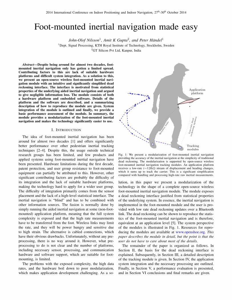
x
y
z
R`−1dp`
R`dp`+1R`+1dp`+2
x`
x`+1
x`+2
Step-wise dead reckoning Step-wise inertial navigation
Fig. 2: Illustration of the step-wise inertial navigation and the step-wise deadreckoning. The displacement and heading change over a step given by theinertial navigation are used to perform the step-wise dead-reckoning.
the translational and in-plane rotation invariance of (1), thisimplies that errors of future states vk+n and [φk+n, θk+n] (n >0) are uncorrelated with those of pk and ψk. Consequently,future ZUPTs cannot be used to deduce information about thecurrent position and heading errors. In turn, this means that,considering only the ZUPTs, it makes no difference if we resetthe system and add the new relative position and heading tothose before the reset. However, for other information sources,we must keep track of the global (total) error covariance ofthe position and heading estimates.
Resetting the system means setting position pk and headingψk and corresponding covariances to zero. Denote the positionand heading estimates at a reset ` by dp` and dψ`. Thesevalues can be used to drive the step-wise dead reckoning[
x`χ`
]=
[x`−1χ`−1
]+
[R`−1dp`dψ`
]+ w` (3)
where x` and χ` are the position and heading of the inertialnavigation system relative to the navigation frame,
R` =
cos(χ`) − sin(χ`) 0sin(χ`) cos(χ`) 0
0 0 1
is the in-plane rotation matrix from the local coordinate frameof the last reset to the navigation frame, and w` is a (byassumption) white noise with covariance,
cov(w`) = cov([R`−1dp`, dψ`]
)=
[R`−1Pp`
R>`−1 R`−1Pp`,ψ`
P>p`,ψ`R>`−1 Pψ`,ψ`
]. (4)
The noise w` in (3) represents the accumulated uncertainty inposition and heading since the last reset, i.e. the essentiallynon-zero elements in (2) transformed to the navigation frame.As described in Section IV, the dead reckoning (3) is easilyused to estimate x` and χ` and their error covariances fromdp` and dψ` and related covariances. The relation between thestep-wise inertial navigation and dead reckoning is illustratedin Fig. 2. Refer to [5] for further details.
The dead reckoning statistical interface (3)-(4) separates thetracking from the high rate inertial navigation. If the ZUPT-aided inertial navigation is implemented with the inertial
2014 International Conference on Indoor Positioning and Indoor Navigation, 27th-30th October 2014
sensors on the foot, then only the low rate steps dp` anddψ` and the related uncertainties Pp`
, Pp`,ψ`, and Pψ`,ψ`
have to be transferred to the user. Due to the decreasedrate and communication bandwidth requirements, a wirelesscommunication link can easily be used while retaining the highrate inertial measurements. However, this requires support of asuitable hardware platform and dedicated embedded software.
III. THE TRACKING MODULES
A handful of inertial platforms can be found in the literature,e.g. [11–16], and on the market, e.g. [17–20]. Unfortunately,none of them fulfill all the requirements to implement theinertial navigation and the dead reckoning interface. For theprocessing, the computational power must be sufficiently high,and it is highly desirable to have a floating point core orcoprocessor. To get satisfactory performance, the inertial sen-sors must have sufficient stability, dynamic range, samplingrate, and analog bandwidth. Further, the platform should beopen (for reprogramming) and reasonably well documented.Finally, the platform should have a suitable wireless linkand be sufficiently small for convenient foot-mounting. Inorder to provide these capabilities, we have designed ourown hardware platform and developed necessary embeddedsoftware, together making up a complete tracking module.
The module is a development and merger of two of ourprevious platforms: the first generation of the OpenShoemodule [11] and the Massive-MIMU platform [21]. Note thatthe module may also be used as a normal (wireless) IMU.
A. Hardware platform
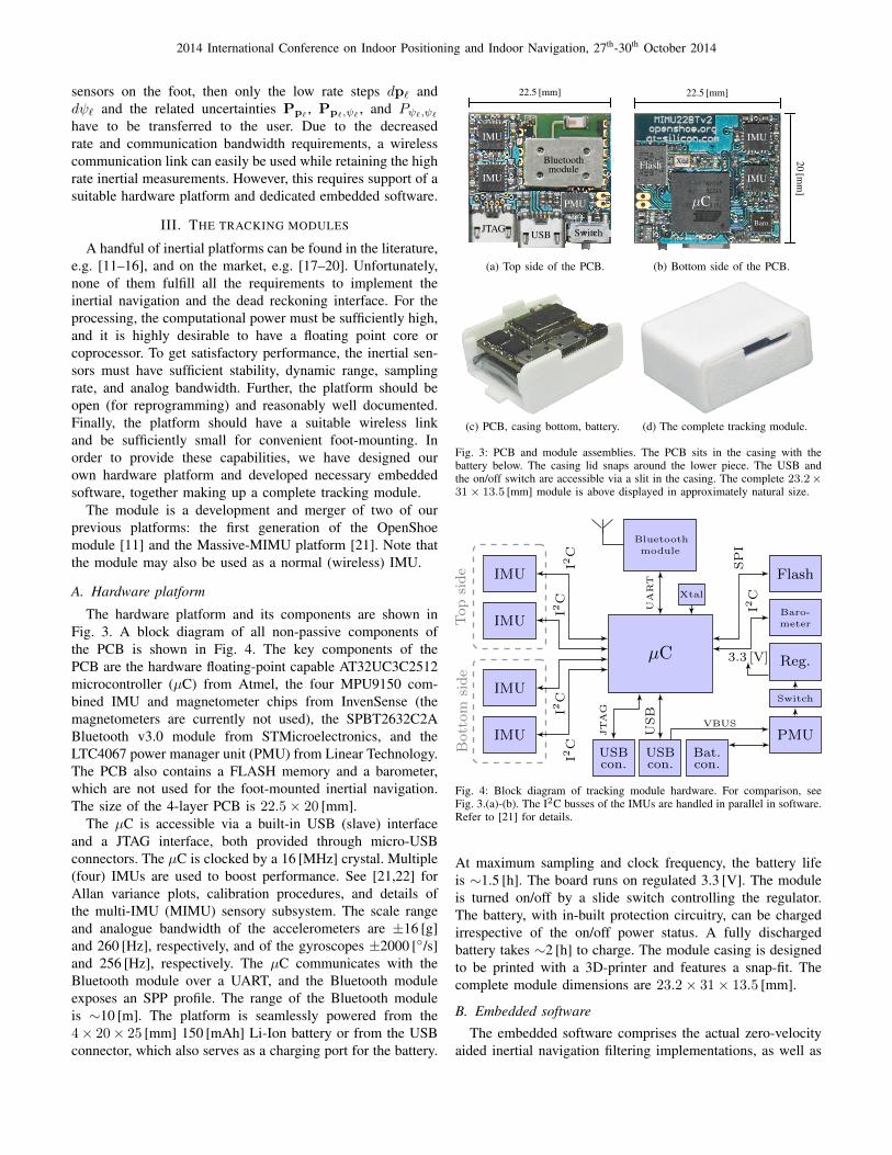
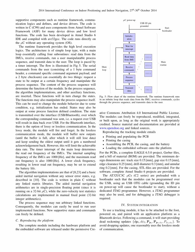
The hardware platform and its components are shown inFig. 3. A block diagram of all non-passive components ofthe PCB is shown in Fig. 4. The key components of thePCB are the hardware floating-point capable AT32UC3C2512microcontroller (µC) from Atmel, the four MPU9150 com-bined IMU and magnetometer chips from InvenSense (themagnetometers are currently not used), the SPBT2632C2ABluetooth v3.0 module from STMicroelectronics, and theLTC4067 power manager unit (PMU) from Linear Technology.The PCB also contains a FLASH memory and a barometer,which are not used for the foot-mounted inertial navigation.The size of the 4-layer PCB is 22.5× 20 [mm].
The µC is accessible via a built-in USB (slave) interfaceand a JTAG interface, both provided through micro-USBconnectors. The µC is clocked by a 16 [MHz] crystal. Multiple(four) IMUs are used to boost performance. See [21,22] forAllan variance plots, calibration procedures, and details ofthe multi-IMU (MIMU) sensory subsystem. The scale rangeand analogue bandwidth of the accelerometers are ±16 [g]and 260 [Hz], respectively, and of the gyroscopes ±2000 [/s]and 256 [Hz], respectively. The µC communicates with theBluetooth module over a UART, and the Bluetooth moduleexposes an SPP profile. The range of the Bluetooth moduleis ∼10 [m]. The platform is seamlessly powered from the4× 20× 25 [mm] 150 [mAh] Li-Ion battery or from the USBconnector, which also serves as a charging port for the battery.
22.5 [mm]
Bluetoothmodule
IMU
IMU
JTAGUSB Switch
PMU
Bat.
(a) Top side of the PCB.
20[m
m]
22.5 [mm]
µC
IMU
IMUFlash
Reg.
Baro.
Xtal
(b) Bottom side of the PCB.
(c) PCB, casing bottom, battery. (d) The complete tracking module.
Fig. 3: PCB and module assemblies. The PCB sits in the casing with thebattery below. The casing lid snaps around the lower piece. The USB andthe on/off switch are accessible via a slit in the casing. The complete 23.2×31× 13.5 [mm] module is above displayed in approximately natural size.
µC
Bluetooth
module
Xtal
UART
IMU
IMU
IMU
IMU
Topside
Bottom
side
I2C
I2C
I2C
I2C
Flash
Baro-
meter
Reg.
Switch
PMUSPI
I2C
3.3 [V]
USBcon.
USBcon.
Bat.con.
VBUS
JTAG
USB
Fig. 4: Block diagram of tracking module hardware. For comparison, seeFig. 3.(a)-(b). The I2C busses of the IMUs are handled in parallel in software.Refer to [21] for details.
At maximum sampling and clock frequency, the battery lifeis ∼1.5 [h]. The board runs on regulated 3.3 [V]. The moduleis turned on/off by a slide switch controlling the regulator.The battery, with in-built protection circuitry, can be chargedirrespective of the on/off power status. A fully dischargedbattery takes ∼2 [h] to charge. The module casing is designedto be printed with a 3D-printer and features a snap-fit. Thecomplete module dimensions are 23.2× 31× 13.5 [mm].
B. Embedded software
The embedded software comprises the actual zero-velocityaided inertial navigation filtering implementations, as well as
2014 International Conference on Indoor Positioning and Indoor Navigation, 27th-30th October 2014
supportive components such as runtime framework, commu-nication logics and defines, and device drivers. The code iswritten in C (C99) and uses components from Atmel SoftwareFramework (ASF) for many device drives and low levelfunctions. The code has been developed in Atmel Studio 6IDE and compiled with avr32gcc. The code runs directly onthe µC without any operating system (OS).
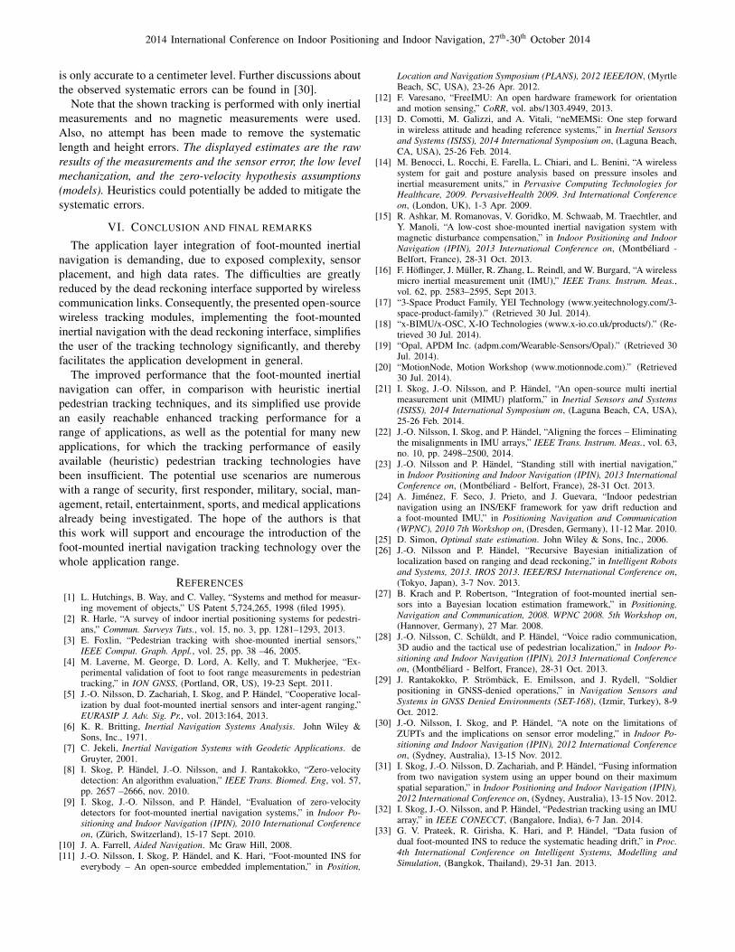
The runtime framework provides the high level executionlogics. The architecture is of simple loop type, with a mainloop essentially calling four subroutines: read data from theIMUs, receive commands, run a user manipulatable processsequence, and transmit data to the user. The loop is paced bya timer interrupt. The flow is illustrated in Fig 5. The serialcommands from the user (consisting of a 1 byte commandheader, a command specific command argument payload, anda 2 byte checksum) can essentially do two things: request astate to be output at a certain frequency and manipulate theprocess sequence. The content of the process sequence willdetermine the function of the module. In the process sequence,the algorithm implementations, and other auxiliary functions,are inserted. These functions will in turn change the states.The functions may also manipulate the process sequence itself.This can be used to change the module behavior due to somecondition, e.g. initialization has ended. States may also beoutput at some process function defined condition. The stateis transmitted over the interface (USB/Bluetooth), over whichthe corresponding command was sent, i.e. a request over USBwill result in data back over USB. For the Bluetooth interface,there is the option of lossy or lossless communication. In thelossy mode, the module will fire and forget. In the losslesscommunication mode, the module will buffer new outputs(until the buffer is full, after which it will still lose data)and keep sending the oldest output until it gets a numberedacknowledgement back. However, this will limit the achievabledata rate. The timer interrupt of the main loop determinesthe read out frequency of the IMUs. The internal samplingfrequency of the IMUs are 1000 [Hz], and the maximum readout frequency is also 1000 [Hz]. A lower clock frequency,resulting in lower read out frequency, may be set to extendthe battery life.
The algorithm implementations are that of [8,23] and a basicaided inertial navigation without any sensor error states, e.g.described in [10]. The code is written in plain C withoutany linked matrix libraries. The aided inertial navigationarithmetics are in single-precision floating point (since it isrunning on a 32-bit µC), while the zero-velocity test statisticscalculations are implemented in manual fixed point (32-bitinteger arithmetics).
The process sequence may run arbitrary linked functions.Consequently, the modules can easily be used to run userimplemented functions. New supportive states and commandscan freely be defined.
C. Reproducing the platform
The complete module including the hardware platform andthe embedded software are released under the permissive Cre-
µC power-upUSB ID pingrounded
Startbootloader
Initializ-ation
Wait forinterrupt
Read datafrom IMU
Receivecommands
Processsequence
Transmitdata
f[0]()
f[1]()
f[2]()
f[N]()
Mainroutine
Mainloop
Fig. 5: Flow chart of the runtime framework. The runtime framework runsin an infinite loop that reads data from the IMU, receives commands, cyclesthrough the process sequence, and transmits data to the user.
ative Commons Attribution 4.0 International Public License.The modules can freely be reproduced, modified, integrated,or built upon, as long as the original work is appropriatelycredited. Source material and documentation are provided atwww.openshoe.org and linked sources.
Reproducing the tracking module entails• Printing and populating the PCB• Printing the casing• Assembling the PCB, the casing, and the battery• Loading the embedded software onto the platform
For the PCBs, a complete EAGLE 6.5.0 project, Gerber files,and a bill of material (BOM) are provided. The minimum de-sign dimensions are: track size 0.15 [mm], gap size 0.15 [mm],edge clearance 0.25 [mm], drill diameter 0.3 [mm], and annularring 0.2 [mm]. For the casing, STL-files are provided. For thesoftware, complete Atmel Studio 6 projects are provided.
The AT32UC3C µCs (C2 series) are preloaded with abootloader such that the modules can be programmed overthe USB, using an USB OTG cable (grounding the ID pinon power-up will cause the bootloader to start), without adedicated JTAG programmer. However, a JTAG programmermay also be used, and for debugging a JTAG debugger isrequired.
IV. SYSTEM INTEGRATION
To use a tracking module, it has to be attached to the foot,powered on, and paired with an application platform as aBluetooth device. Following a command, it will start providingdead reckoning updates dp`, dψ`,Pp`
,Pp`,ψ`, Pψ`,ψ`
. Toavoid dropping updates, one reasonably uses the lossless modeof communication.
2014 International Conference on Indoor Positioning and Indoor Navigation, 27th-30th October 2014
To track the user and fuse the data with other informationsources, the updates have to be “summed up”. This is doneby [
x`χ`
]=
[x`−1χ`−1
]+
[R`−1dp`dψ`
]P` = F(θ`−1,dx`,dy`)P`−1F
>(θ`−1,dx`,dy`)
+
[R`−1Pp`
R>`−1 R`−1Pp`,ψ`
P>p`,ψ`R>`−1 Pψ`,ψ`
]where the system matrix is
F(θk−1,dx`,dy`)=
1 0 0 − sin(θ`−1)dx`− cos(θ`−1)dy`0 1 0 cos(θ`−1)dx`− sin(θ`−1)dy`0 0 1 00 0 0 1
.With the dead reckoning interface, this is the only foot-mounted inertial navigation specific processing which hasto be performed. For complexity comparison and a detaileddescription of the complete foot-mounted inertial navigationprocessing, see [8,24]. The estimates [x`, χ`] and P` providethe mean and covariance of the state (position and heading) ofthe user and may be appended to other states and covariancesof the system. Combined with standard Bayesian state esti-mation methods, see e.g. [25], this may be used to fuse theinertial tracking with other information sources. For furtherdetails and examples of how to fuse the tracking with otherinformation sources, see [5,26–28].
V. PERFORMANCE
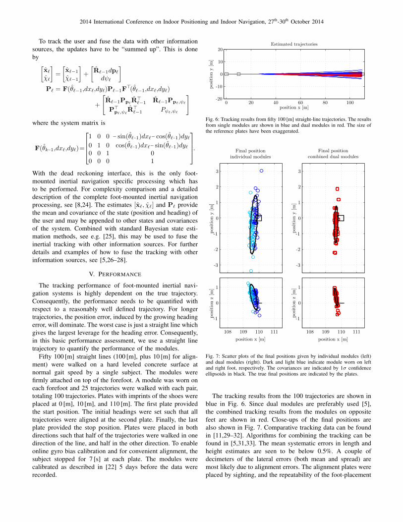
The tracking performance of foot-mounted inertial navi-gation systems is highly dependent on the true trajectory.Consequently, the performance needs to be quantified withrespect to a reasonably well defined trajectory. For longertrajectories, the position error, induced by the growing headingerror, will dominate. The worst case is just a straight line whichgives the largest leverage for the heading error. Consequently,in this basic performance assessment, we use a straight linetrajectory to quantify the performance of the modules.
Fifty 100 [m] straight lines (100 [m], plus 10 [m] for align-ment) were walked on a hard leveled concrete surface atnormal gait speed by a single subject. The modules werefirmly attached on top of the forefoot. A module was worn oneach forefoot and 25 trajectories were walked with each pair,totaling 100 trajectories. Plates with imprints of the shoes wereplaced at 0 [m], 10 [m], and 110 [m]. The first plate providedthe start position. The initial headings were set such that alltrajectories were aligned at the second plate. Finally, the lastplate provided the stop position. Plates were placed in bothdirections such that half of the trajectories were walked in onedirection of the line, and half in the other direction. To enableonline gyro bias calibration and for convenient alignment, thesubject stopped for 7 [s] at each plate. The modules werecalibrated as described in [22] 5 days before the data wererecorded.
Estimated trajectories
position x [m]
positiony[m
]
20
20
10
0
0
-10
-2040 60 80 100
Fig. 6: Tracking results from fifty 100 [m] straight-line trajectories. The resultsfrom single modules are shown in blue and dual modules in red. The size ofthe reference plates have been exaggerated.
qwert
Final positionindividual modules
Final positioncombined dual modules
positiony[m
]
positiony[m
]
33
22
11
00
-1-1
-2-2
-3-3
position x [m]
positionz[m
]
position x [m]
positionz[m
] 11
00
-1-1
108108 109109 110110 111111
Fig. 7: Scatter plots of the final positions given by individual modules (left)and dual modules (right). Dark and light blue indicate module worn on leftand right foot, respectively. The covariances are indicated by 1σ confidenceellipsoids in black. The true final positions are indicated by the plates.
The tracking results from the 100 trajectories are shown inblue in Fig. 6. Since dual modules are preferably used [5],the combined tracking results from the modules on oppositefeet are shown in red. Close-ups of the final positions arealso shown in Fig. 7. Comparative tracking data can be foundin [11,29–32]. Algorithms for combining the tracking can befound in [5,31,33]. The mean systematic errors in length andheight estimates are seen to be below 0.5%. A couple ofdecimeters of the lateral errors (both mean and spread) aremost likely due to alignment errors. The alignment plates wereplaced by sighting, and the repeatability of the foot-placement
2014 International Conference on Indoor Positioning and Indoor Navigation, 27th-30th October 2014
is only accurate to a centimeter level. Further discussions aboutthe observed systematic errors can be found in [30].
Note that the shown tracking is performed with only inertialmeasurements and no magnetic measurements were used.Also, no attempt has been made to remove the systematiclength and height errors. The displayed estimates are the rawresults of the measurements and the sensor error, the low levelmechanization, and the zero-velocity hypothesis assumptions(models). Heuristics could potentially be added to mitigate thesystematic errors.
VI. CONCLUSION AND FINAL REMARKS
The application layer integration of foot-mounted inertialnavigation is demanding, due to exposed complexity, sensorplacement, and high data rates. The difficulties are greatlyreduced by the dead reckoning interface supported by wirelesscommunication links. Consequently, the presented open-sourcewireless tracking modules, implementing the foot-mountedinertial navigation with the dead reckoning interface, simplifiesthe user of the tracking technology significantly, and therebyfacilitates the application development in general.
The improved performance that the foot-mounted inertialnavigation can offer, in comparison with heuristic inertialpedestrian tracking techniques, and its simplified use providean easily reachable enhanced tracking performance for arange of applications, as well as the potential for many newapplications, for which the tracking performance of easilyavailable (heuristic) pedestrian tracking technologies havebeen insufficient. The potential use scenarios are numerouswith a range of security, first responder, military, social, man-agement, retail, entertainment, sports, and medical applicationsalready being investigated. The hope of the authors is thatthis work will support and encourage the introduction of thefoot-mounted inertial navigation tracking technology over thewhole application range.
REFERENCES[1] L. Hutchings, B. Way, and C. Valley, “Systems and method for measur-
ing movement of objects,” US Patent 5,724,265, 1998 (filed 1995).[2] R. Harle, “A survey of indoor inertial positioning systems for pedestri-
ans,” Commun. Surveys Tuts., vol. 15, no. 3, pp. 1281–1293, 2013.[3] E. Foxlin, “Pedestrian tracking with shoe-mounted inertial sensors,”
IEEE Comput. Graph. Appl., vol. 25, pp. 38 –46, 2005.[4] M. Laverne, M. George, D. Lord, A. Kelly, and T. Mukherjee, “Ex-
perimental validation of foot to foot range measurements in pedestriantracking,” in ION GNSS, (Portland, OR, US), 19-23 Sept. 2011.
[5] J.-O. Nilsson, D. Zachariah, I. Skog, and P. Handel, “Cooperative local-ization by dual foot-mounted inertial sensors and inter-agent ranging,”EURASIP J. Adv. Sig. Pr., vol. 2013:164, 2013.
[6] K. R. Britting, Inertial Navigation Systems Analysis. John Wiley &Sons, Inc., 1971.
[7] C. Jekeli, Inertial Navigation Systems with Geodetic Applications. deGruyter, 2001.
[8] I. Skog, P. Handel, J.-O. Nilsson, and J. Rantakokko, “Zero-velocitydetection: An algorithm evaluation,” IEEE Trans. Biomed. Eng, vol. 57,pp. 2657 –2666, nov. 2010.
[9] I. Skog, J.-O. Nilsson, and P. Handel, “Evaluation of zero-velocitydetectors for foot-mounted inertial navigation systems,” in Indoor Po-sitioning and Indoor Navigation (IPIN), 2010 International Conferenceon, (Zurich, Switzerland), 15-17 Sept. 2010.
[10] J. A. Farrell, Aided Navigation. Mc Graw Hill, 2008.[11] J.-O. Nilsson, I. Skog, P. Handel, and K. Hari, “Foot-mounted INS for
everybody – An open-source embedded implementation,” in Position,
Location and Navigation Symposium (PLANS), 2012 IEEE/ION, (MyrtleBeach, SC, USA), 23-26 Apr. 2012.
[12] F. Varesano, “FreeIMU: An open hardware framework for orientationand motion sensing,” CoRR, vol. abs/1303.4949, 2013.
[13] D. Comotti, M. Galizzi, and A. Vitali, “neMEMSi: One step forwardin wireless attitude and heading reference systems,” in Inertial Sensorsand Systems (ISISS), 2014 International Symposium on, (Laguna Beach,CA, USA), 25-26 Feb. 2014.
[14] M. Benocci, L. Rocchi, E. Farella, L. Chiari, and L. Benini, “A wirelesssystem for gait and posture analysis based on pressure insoles andinertial measurement units,” in Pervasive Computing Technologies forHealthcare, 2009. PervasiveHealth 2009. 3rd International Conferenceon, (London, UK), 1-3 Apr. 2009.
[15] R. Ashkar, M. Romanovas, V. Goridko, M. Schwaab, M. Traechtler, andY. Manoli, “A low-cost shoe-mounted inertial navigation system withmagnetic disturbance compensation,” in Indoor Positioning and IndoorNavigation (IPIN), 2013 International Conference on, (Montbeliard -Belfort, France), 28-31 Oct. 2013.
[16] F. Hoflinger, J. Muller, R. Zhang, L. Reindl, and W. Burgard, “A wirelessmicro inertial measurement unit (IMU),” IEEE Trans. Instrum. Meas.,vol. 62, pp. 2583–2595, Sept 2013.
[17] “3-Space Product Family, YEI Technology (www.yeitechnology.com/3-space-product-family).” (Retrieved 30 Jul. 2014).
[18] “x-BIMU/x-OSC, X-IO Technologies (www.x-io.co.uk/products/).” (Re-trieved 30 Jul. 2014).
[19] “Opal, APDM Inc. (adpm.com/Wearable-Sensors/Opal).” (Retrieved 30Jul. 2014).
[20] “MotionNode, Motion Workshop (www.motionnode.com).” (Retrieved30 Jul. 2014).
[21] I. Skog, J.-O. Nilsson, and P. Handel, “An open-source multi inertialmeasurement unit (MIMU) platform,” in Inertial Sensors and Systems(ISISS), 2014 International Symposium on, (Laguna Beach, CA, USA),25-26 Feb. 2014.
[22] J.-O. Nilsson, I. Skog, and P. Handel, “Aligning the forces – Eliminatingthe misalignments in IMU arrays,” IEEE Trans. Instrum. Meas., vol. 63,no. 10, pp. 2498–2500, 2014.
[23] J.-O. Nilsson and P. Handel, “Standing still with inertial navigation,”in Indoor Positioning and Indoor Navigation (IPIN), 2013 InternationalConference on, (Montbeliard - Belfort, France), 28-31 Oct. 2013.
[24] A. Jimenez, F. Seco, J. Prieto, and J. Guevara, “Indoor pedestriannavigation using an INS/EKF framework for yaw drift reduction anda foot-mounted IMU,” in Positioning Navigation and Communication(WPNC), 2010 7th Workshop on, (Dresden, Germany), 11-12 Mar. 2010.
[25] D. Simon, Optimal state estimation. John Wiley & Sons, Inc., 2006.[26] J.-O. Nilsson and P. Handel, “Recursive Bayesian initialization of
localization based on ranging and dead reckoning,” in Intelligent Robotsand Systems, 2013. IROS 2013. IEEE/RSJ International Conference on,(Tokyo, Japan), 3-7 Nov. 2013.
[27] B. Krach and P. Robertson, “Integration of foot-mounted inertial sen-sors into a Bayesian location estimation framework,” in Positioning,Navigation and Communication, 2008. WPNC 2008. 5th Workshop on,(Hannover, Germany), 27 Mar. 2008.
[28] J.-O. Nilsson, C. Schuldt, and P. Handel, “Voice radio communication,3D audio and the tactical use of pedestrian localization,” in Indoor Po-sitioning and Indoor Navigation (IPIN), 2013 International Conferenceon, (Montbeliard - Belfort, France), 28-31 Oct. 2013.
[29] J. Rantakokko, P. Stromback, E. Emilsson, and J. Rydell, “Soldierpositioning in GNSS-denied operations,” in Navigation Sensors andSystems in GNSS Denied Environments (SET-168), (Izmir, Turkey), 8-9Oct. 2012.
[30] J.-O. Nilsson, I. Skog, and P. Handel, “A note on the limitations ofZUPTs and the implications on sensor error modeling,” in Indoor Po-sitioning and Indoor Navigation (IPIN), 2012 International Conferenceon, (Sydney, Australia), 13-15 Nov. 2012.
[31] I. Skog, J.-O. Nilsson, D. Zachariah, and P. Handel, “Fusing informationfrom two navigation system using an upper bound on their maximumspatial separation,” in Indoor Positioning and Indoor Navigation (IPIN),2012 International Conference on, (Sydney, Australia), 13-15 Nov. 2012.
[32] I. Skog, J.-O. Nilsson, and P. Handel, “Pedestrian tracking using an IMUarray,” in IEEE CONECCT, (Bangalore, India), 6-7 Jan. 2014.
[33] G. V. Prateek, R. Girisha, K. Hari, and P. Handel, “Data fusion ofdual foot-mounted INS to reduce the systematic heading drift,” in Proc.4th International Conference on Intelligent Systems, Modelling andSimulation, (Bangkok, Thailand), 29-31 Jan. 2013.