Embed Size (px)
Citation preview
1. Installing the application
PC version: Start AlfaOBDsetup.exe and follow the setup guidance. Alternatively, download AlfaOBD_PC.rar
archive and extract it to any folder on the hard drive and start AlfaOBD.exe. Confirm administrator permission
if requested to start the program. Note: .Net runtime of ver.3.5 or above has to be installed on the PC.
PDA version: There is no installer provided. Extract the downloaded archive to any folder on your PDA and
start AlfaOBD.exe.
Note: PDA version is supported on Windows Mobile platform only.
At the first launch the application displays license agreement which you have to accept by checking "Accept"
check box and clicking "Continue". If you do not accept the agreement the application will terminate.
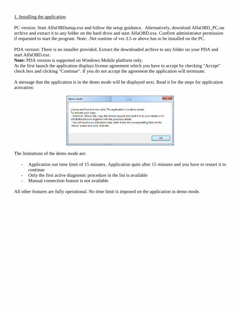
A message that the application is in the demo mode will be displayed next. Read it for the steps for application
activation:
The limitations of the demo mode are:
- Application run time limit of 15 minutes. Application quits after 15 minutes and you have to restart it to
continue
- Only the first active diagnostic procedure in the list is available
- Manual connection feature is not available
All other features are fully operational. No time limit is imposed on the application in demo mode.
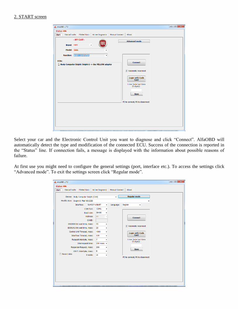
2. START screen
Select your car and the Electronic Control Unit you want to diagnose and click “Connect”. AlfaOBD will
automatically detect the type and modification of the connected ECU. Success of the connection is reported in
the “Status” line. If connection fails, a message is displayed with the information about possible reasons of
failure.
At first use you might need to configure the general settings (port, interface etc.). To access the settings click
“Advanced mode”. To exit the settings screen click “Regular mode”.
You can select electronic control unit (ECU) to connect in the "Device" list. Each ECU in the list represents a
group of modifications which can be additionally selected in the “Modification” box. The ECUs are grouped in
the list according to their function. If you do not know the type of ECU installed in your car, you can select
generic one (for example, --ENGINE-- or –GEARBOX--). At connect time AlfaOBD automatically detects the
ECU type and adjusts the ECU selection in the “Device” box and it’s modification in the “Modification” box. If
the connected ECU is not yet fully supported, generic support might be available, i.e. reading of device id and
stored faults without detailed data.
Note: The selection of the ECU and its modification done in advanced mode is not reflected on the “Regular
mode” screen.
The automatic detection can take some time, so after learning of your car configuration you can select correct
ECU and modification to save the connection time. In the current version the automatic detection is
implemented for selected groups of ECUs (if the “Connect” button is disabled after selecting a generic function,
that means the automatic detection is not implemented for the selected function yet), in the next versions this
feature will be enhanced.
The OBD interface used is selected in the "Interface" list.
At present there are four types of interfaces supported:
1. KLLine serial or USB. Only the K-Line based ECUs are supported. No CAN support can be provided with
this simple interface.
2. OBDKey Bluetooth, USB, and WLAN http://www.obdkey.com/vehiclediagnostics.asp. This interface is a
universal one supporting all listed ECUs, both K-Line and CAN-based. Additional advantage of the interface is
that firmware upgrade is provided by the producer if needed.
3. ELM327-based Bluetooth, USB, and WLAN interface. There are many suppliers of such interfaces, make
sure the version is 1.3 and above. The interface support all CAN and most of the K-Line units. A rule of thumb
is that the K-Line units with a connection baud rate which is less than 10400 bps will not be supported.
4. OBDLink SX/MX https://www.scantool.net . The same limitations as for ELM327 interface apply. The
advantage of OBDLink is high communication rate of 115200 bps with the PC.
For the latest update on interface support and recommended interfaces, as well as details of the interface
capability to support different units, see http://www.alfaobd.com .
If you are using Windows PDA version of AlfaOBD, the following limitations apply:
1. USB interfaces are not supported because most PDAs do not have USB-host built in.
2. KLLine serial interface is supported for PDAs based on PXA processor (Intel/Marvel). Experimental support
of Samsung and OMAP processors is implemented without guaranty. Modern PDAs (and especially
communicators) might not have serial port plug at all, in that case the choice is an OBDKey/ELM327 Bluetooth
interface.
Note: Some PDAs do have a serial port plug even if the manufacturer does not mention it in the manuals. There
might be third-party suppliers of serial cables for your PDA. You need a "modem" cable, the ActiveSync one
will not work. Also, you can make a cable yourself if you are familiar with welding iron and RS232 standards.
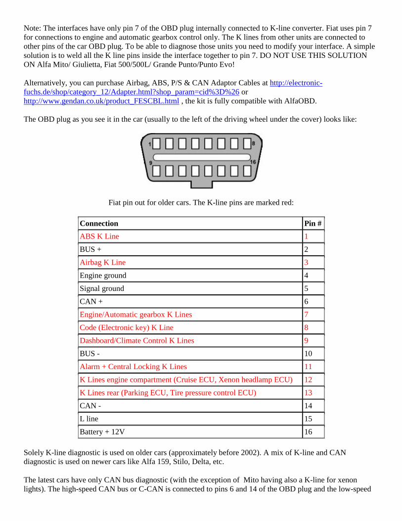
Note: The interfaces have only pin 7 of the OBD plug internally connected to K-line converter. Fiat uses pin 7
for connections to engine and automatic gearbox control only. The K lines from other units are connected to
other pins of the car OBD plug. To be able to diagnose those units you need to modify your interface. A simple
solution is to weld all the K line pins inside the interface together to pin 7. DO NOT USE THIS SOLUTION
ON Alfa Mito/ Giulietta, Fiat 500/500L/ Grande Punto/Punto Evo!
Alternatively, you can purchase Airbag, ABS, P/S & CAN Adaptor Cables at http://electronic-
fuchs.de/shop/category_12/Adapter.html?shop_param=cid%3D%26 or
http://www.gendan.co.uk/product_FESCBL.html , the kit is fully compatible with AlfaOBD.
The OBD plug as you see it in the car (usually to the left of the driving wheel under the cover) looks like:
Fiat pin out for older cars. The K-line pins are marked red:
Connection Pin #
ABS K Line 1
BUS + 2
Airbag K Line 3
Engine ground 4
Signal ground 5
CAN + 6
Engine/Automatic gearbox K Lines 7
Code (Electronic key) K Line 8
Dashboard/Climate Control K Lines 9
BUS - 10
Alarm + Central Locking K Lines 11
K Lines engine compartment (Cruise ECU, Xenon headlamp ECU) 12
K Lines rear (Parking ECU, Tire pressure control ECU) 13
CAN - 14
L line 15
Battery + 12V 16
Solely K-line diagnostic is used on older cars (approximately before 2002). A mix of K-line and CAN
diagnostic is used on newer cars like Alfa 159, Stilo, Delta, etc.
The latest cars have only CAN bus diagnostic (with the exception of Mito having also a K-line for xenon
lights). The high-speed CAN bus or C-CAN is connected to pins 6 and 14 of the OBD plug and the low-speed
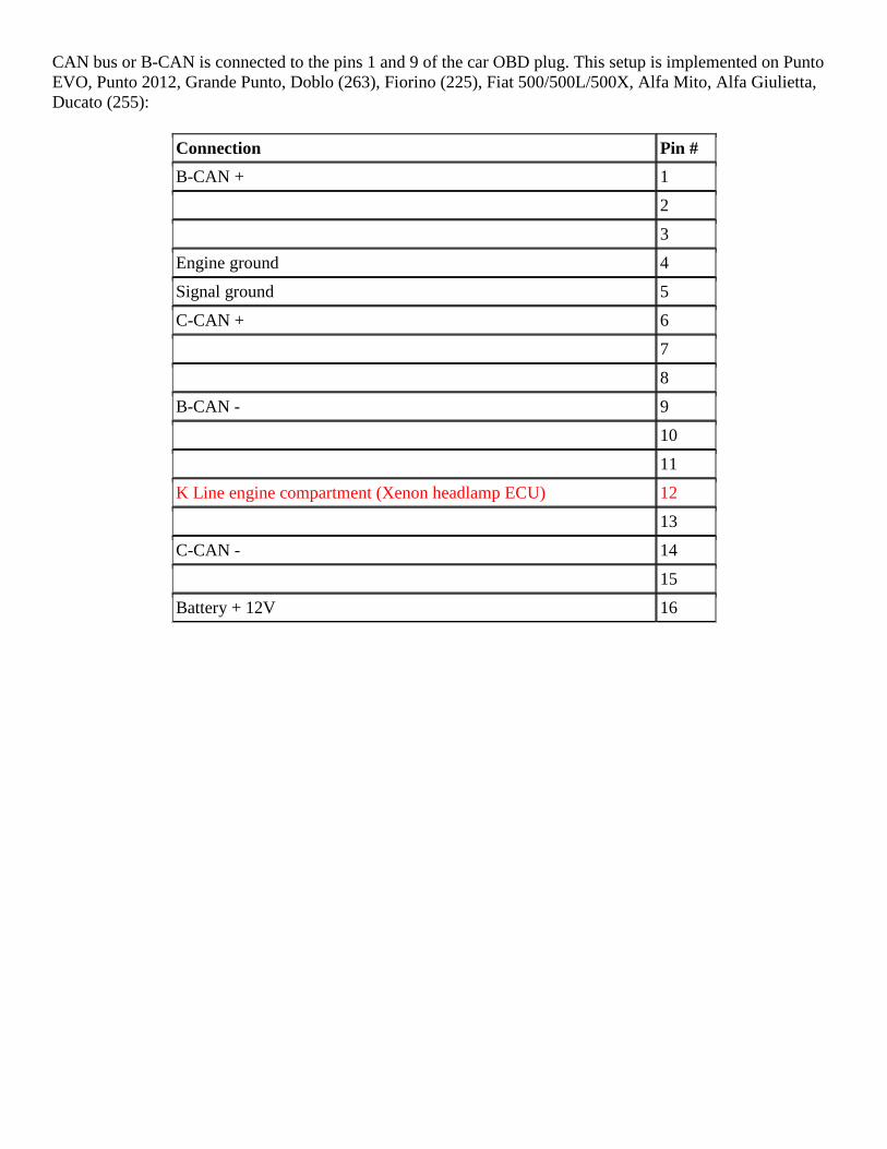
CAN bus or B-CAN is connected to the pins 1 and 9 of the car OBD plug. This setup is implemented on Punto
EVO, Punto 2012, Grande Punto, Doblo (263), Fiorino (225), Fiat 500/500L/500X, Alfa Mito, Alfa Giulietta,
Ducato (255):
Connection Pin #
B-CAN + 1
2
3
Engine ground 4
Signal ground 5
C-CAN + 6
7
8
B-CAN - 9
10
11
K Line engine compartment (Xenon headlamp ECU) 12
13
C-CAN - 14
15
Battery + 12V 16
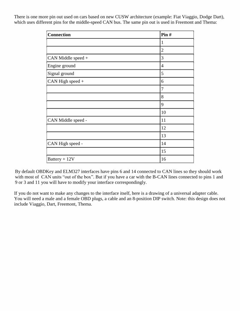
There is one more pin out used on cars based on new CUSW architecture (example: Fiat Viaggio, Dodge Dart),
which uses different pins for the middle-speed CAN bus. The same pin out is used in Freemont and Thema:
Connection Pin #
1
2
CAN Middle speed + 3
Engine ground 4
Signal ground 5
CAN High speed + 6
7
8
9
10
CAN Middle speed - 11
12
13
CAN High speed - 14
15
Battery + 12V 16
By default OBDKey and ELM327 interfaces have pins 6 and 14 connected to CAN lines so they should work
with most of CAN units “out of the box”. But if you have a car with the B-CAN lines connected to pins 1 and
9 or 3 and 11 you will have to modify your interface correspondingly.
If you do not want to make any changes to the interface itself, here is a drawing of a universal adapter cable.
You will need a male and a female OBD plugs, a cable and an 8-position DIP switch. Note: this design does not
include Viaggio, Dart, Freemont, Thema.
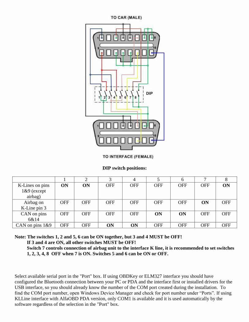
DIP switch positions:
1 2 3 4 5 6 7 8
K-Lines on pins
1&9 (except
airbag)
ON ON OFF OFF OFF OFF OFF ON
Airbag on
K-Line pin 3
OFF OFF OFF OFF OFF OFF ON OFF
CAN on pins
6&14
OFF OFF OFF OFF ON ON OFF OFF
CAN on pins 1&9 OFF OFF ON ON OFF OFF OFF OFF
Note: The switches 1, 2 and 5, 6 can be ON together, but 3 and 4 MUST be OFF!
If 3 and 4 are ON, all other switches MUST be OFF!
Switch 7 controls connection of airbag unit to the interface K line, it is recommended to set switches
1, 2, 3, 4, 8 OFF when 7 is ON. Switches 5 and 6 can be ON or OFF.
Select available serial port in the "Port" box. If using OBDKey or ELM327 interface you should have
configured the Bluetooth connection between your PC or PDA and the interface first or installed drivers for the
USB interface, so you should already know the number of the COM port created during the installation. To
find the COM port number, open Windows Device Manager and check for port number under “Ports”. If using
KLLine interface with AlfaOBD PDA version, only COM1 is available and it is used automatically by the
software regardless of the selection in the "Port" box.
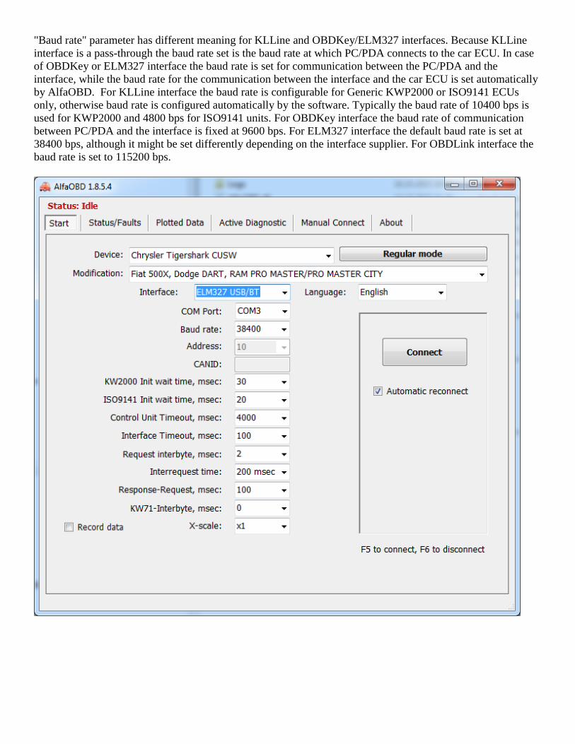
"Baud rate" parameter has different meaning for KLLine and OBDKey/ELM327 interfaces. Because KLLine
interface is a pass-through the baud rate set is the baud rate at which PC/PDA connects to the car ECU. In case
of OBDKey or ELM327 interface the baud rate is set for communication between the PC/PDA and the
interface, while the baud rate for the communication between the interface and the car ECU is set automatically
by AlfaOBD. For KLLine interface the baud rate is configurable for Generic KWP2000 or ISO9141 ECUs
only, otherwise baud rate is configured automatically by the software. Typically the baud rate of 10400 bps is
used for KWP2000 and 4800 bps for ISO9141 units. For OBDKey interface the baud rate of communication
between PC/PDA and the interface is fixed at 9600 bps. For ELM327 interface the default baud rate is set at
38400 bps, although it might be set differently depending on the interface supplier. For OBDLink interface the
baud rate is set to 115200 bps.
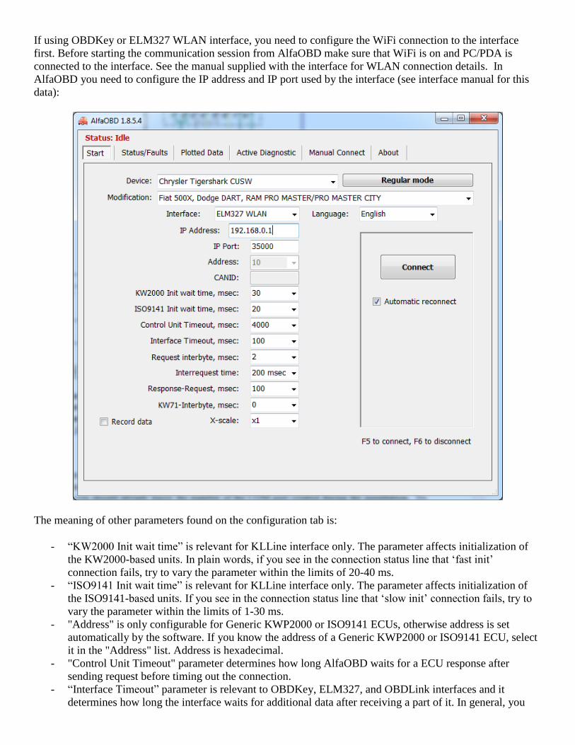
If using OBDKey or ELM327 WLAN interface, you need to configure the WiFi connection to the interface
first. Before starting the communication session from AlfaOBD make sure that WiFi is on and PC/PDA is
connected to the interface. See the manual supplied with the interface for WLAN connection details. In
AlfaOBD you need to configure the IP address and IP port used by the interface (see interface manual for this
data):
The meaning of other parameters found on the configuration tab is:
- “KW2000 Init wait time” is relevant for KLLine interface only. The parameter affects initialization of
the KW2000-based units. In plain words, if you see in the connection status line that ‘fast init’
connection fails, try to vary the parameter within the limits of 20-40 ms.
- “ISO9141 Init wait time” is relevant for KLLine interface only. The parameter affects initialization of
the ISO9141-based units. If you see in the connection status line that ‘slow init’ connection fails, try to
vary the parameter within the limits of 1-30 ms.
- "Address" is only configurable for Generic KWP2000 or ISO9141 ECUs, otherwise address is set
automatically by the software. If you know the address of a Generic KWP2000 or ISO9141 ECU, select
it in the "Address" list. Address is hexadecimal.
- "Control Unit Timeout" parameter determines how long AlfaOBD waits for a ECU response after
sending request before timing out the connection.
- “Interface Timeout” parameter is relevant to OBDKey, ELM327, and OBDLink interfaces and it
determines how long the interface waits for additional data after receiving a part of it. In general, you
should keep this parameter as low as possible to speed up communication. For the most of the units the
default 100 ms is OK, but if after the connection has been done there is a message that it’s impossible to
verify the connected unit, try to increase/decrease this parameter and reconnect.
- "Request Interbyte" is the time between bytes in a request. This parameter can be the most important one
for the communication stability for the KW2000 and ISO9141 based ECU! Usually 4 - 6 ms is the
optimal setting for KLLine and 2 ms for OBDKey interface. Not applicable for ELM327/OBDLink
interfaces or ABS5.3 and engine Bosch ME3.7.1, M1.7/2.7, MA 1.7 control units.
- "Interrequest time" parameter is logically connected with the "Response-Request" one. The
communication between AlfaOBD and ECU is serial, that means it proceeds by series of request -
response cycles. After sending a request for data or action, AlfaOBD waits for a response from the ECU.
Only after receiving the response within the timeout limit, AlfaOBD can send next request. Even if no
requests for data or action is made by AlfaOBD, still it has to keep sending "Tester present" (or "Keep
alive") requests, otherwise connection will be terminated by the ECU. Typical time of complete request-
response cycle is about 200ms. So the "Response-Request" parameter determines time between end of
ECU response and next request ("keep alive" or request for data). Normally you can set this parameter to
zero but sometimes to improve stability of communication it is recommended to increase the value.
"Interrequest time" is the time between consecutive requests, it varies from 200ms to 60sec. A
longer period might be of use when scanning for slow changing data, like engine coolant or passenger
compartment temperature. If high Interrequest time is selected, AlfaOBD automatically sends "keep
alive" messages to ECU between the requests for data to prevent communication breakdown. If total
"Response-Request" value and request-response cycle time are higher than "Interrequest" value selected,
AlfaOBD built-in algorithm optimizes communication timing considering also the timeout defined in the
data exchange protocol specifications.
- "KW71-Interbyte" is only applicable for ABS5.3 and Bosch ME3.7.1, M1.7/2.7, MA 1.7 ECUs. The
data exchange is different from the one described above, the communication proceeds byte-by-byte. The
parameter defines the time between the moment AlfaOBD receives a byte from ECU and the moment it
sends a byte to ECU. 5 ms is usually fine.
- "X-scale" parameter influences plotted data display. By default, one point on the X-axis of the graph
correspond to one measurement. You can increase this ratio for plot readability.
- "Record data" checkbox is for support and debugging purposes only, it should be checked when
AlfaOBD Software needs data for troubleshooting. AlfaOBD creates AlfaOBD_Debug.bin file in the
Data subfolder of the application installation folder. Normally the check box should be unchecked,
because recording of the debug data creates substantial overhead, especially on a PDA.
In the PC version the Start screen contains "Connect" and "Login with CodeCard" buttons, which are placed in
a separate tab in the PDA version due to space limitations.
"Connect" is self-explanatory and it is logically the first button to click after the configuration has been
performed and ECU selected. Please make sure that the ignition key is in MAR before activating connection.
There are several exceptions to the “key in MAR” rule, some units can be also connected to with the key in
Stop, see on-screen guidance.
The following connection algorithm is used by AlfaOBD:
- for the KWP2000-based ECUs three attempts with "fast init" are done, then two more with "slow init". If
unsuccessful, the application switches to "Idle" mode and a failure message is displayed.
- for the ISO9141 or KW71-based ECUs two attempts are done with "slow init". If unsuccessful, the application
switches to "Idle" mode and a failure message is displayed.
- for the CAN-based ECUs three attempts are done. If unsuccessful, the application switches to "Idle" mode and
a failure message is displayed.
Hint: if communication cannot be established, turn the ignition key to Stop, wait 30 sec then turn key to MAR
and retry connection. If using an OBDKey or ELM327 Bluetooth/USB interface, also try to reset it by taking it
out of the OBD plug and inserting it back.
Hint: On some cars (e.g. Alfa GTV) connection to certain units (airbag, ABS) can only be established when
Code control unit is deactivated (the key is not recognized and the CODE light is on). To deactivate the Code
control unit disconnect antenna plug at the Code control ECU.
If "Automatic reconnect" is checked AlfaOBD automatically tries to re-connect when communication breaks.
The status of communication is reflected in the status line on top of the application window (PC version) or as
the application name (PDA version). When communication has been established, you can proceed with reading
fault codes, running active diagnostics, or scanning sensor data at the next tabs.
"Login with code card" is enabled for certain units only (engine control units, Body computer, Steering lock,
TEG reader, Code control, Central Lock RF receiver). You have to login with Code Card when running some
active diagnostic or configuration procedures on these units. Login with Code Card might be of use when, for
example, there is a problem with Code control unit which prevents engine from starting. Connect to the
corresponding engine control unit, enter 5-digit code from the Code Card supplied with your car and click
"Login with code card". Engine control unit does not provide any information whether login is successful or
not. Just try starting your car with ignition key, but do not turn the key to Stop while starting the engine, if you
do this the login has to be repeated.
Units other than engine ECUs provide information about success of the login, it is displayed by the software in
the status line.
Note: The Steering lock unit accepts the login only when key is in ‘Stop’ position.
Note: if your Code Card has been lost, contact your Fiat dealer for replacement.
For the Central Lock RF receiver unit you need to login with password before running some diagnostic
procedures. The password is not the same as the code from the Code Card and it is not supplied with the car.
You might try to obtain it from your Fiat dealer. The Central Lock RF receiver does not provide any
information whether login is successful or not, so AlfaOBD just displays a message about the status of the login
attempt (accepted or rejected). If the entered password is incorrect, the corresponding configuration procedures
will be rejected by the Central Lock RF receiver.
You can save the code and the password to be entered automatically into the box in the future. Only one code
and one password can be saved. Be aware of the security risk! The procedure of logging with code card can be
used to bypass the immobilizer.
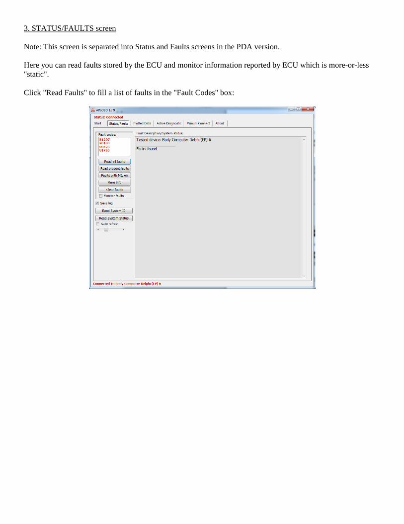
3. STATUS/FAULTS screen
Note: This screen is separated into Status and Faults screens in the PDA version.
Here you can read faults stored by the ECU and monitor information reported by ECU which is more-or-less
"static".
Click "Read Faults" to fill a list of faults in the "Fault Codes" box:
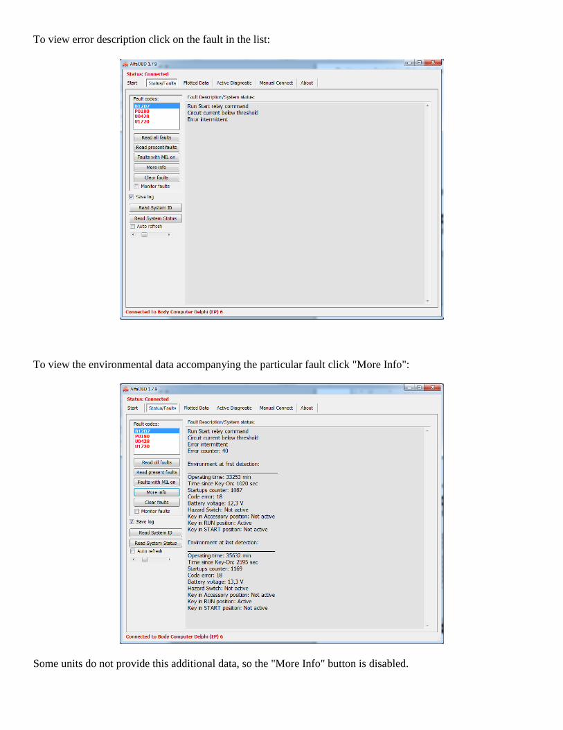
To view error description click on the fault in the list:
To view the environmental data accompanying the particular fault click "More Info":
Some units do not provide this additional data, so the "More Info" button is disabled.
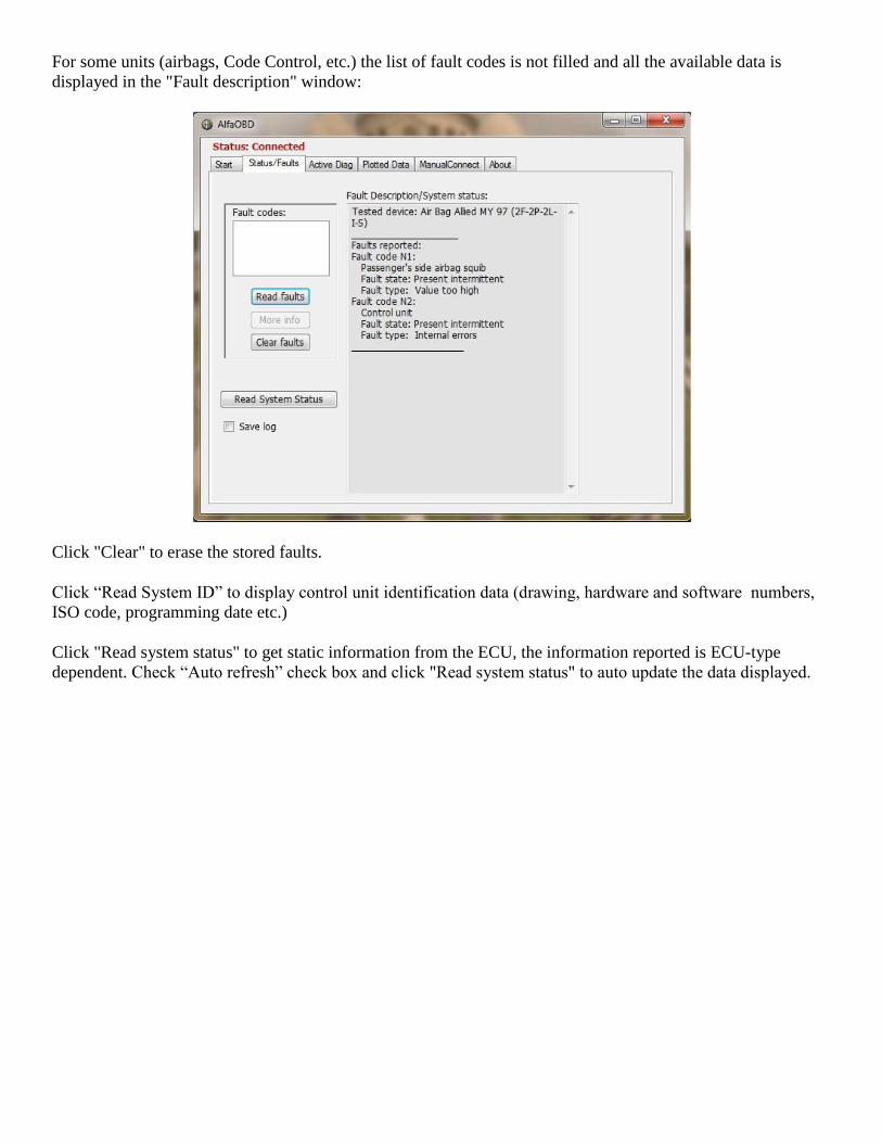
For some units (airbags, Code Control, etc.) the list of fault codes is not filled and all the available data is
displayed in the "Fault description" window:
Click "Clear" to erase the stored faults.
Click “Read System ID” to display control unit identification data (drawing, hardware and software numbers,
ISO code, programming date etc.)
Click "Read system status" to get static information from the ECU, the information reported is ECU-type
dependent. Check “Auto refresh” check box and click "Read system status" to auto update the data displayed.
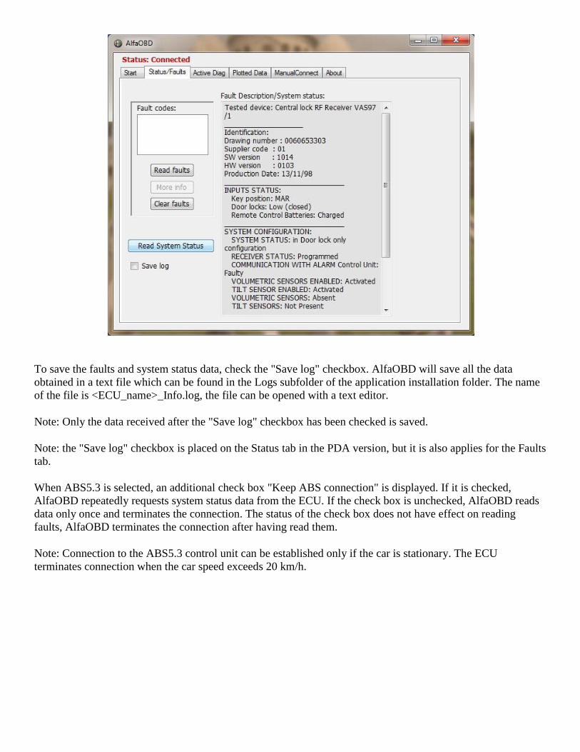
To save the faults and system status data, check the "Save log" checkbox. AlfaOBD will save all the data
obtained in a text file which can be found in the Logs subfolder of the application installation folder. The name
of the file is <ECU_name>_Info.log, the file can be opened with a text editor.
Note: Only the data received after the "Save log" checkbox has been checked is saved.
Note: the "Save log" checkbox is placed on the Status tab in the PDA version, but it is also applies for the Faults
tab.
When ABS5.3 is selected, an additional check box "Keep ABS connection" is displayed. If it is checked,
AlfaOBD repeatedly requests system status data from the ECU. If the check box is unchecked, AlfaOBD reads
data only once and terminates the connection. The status of the check box does not have effect on reading
faults, AlfaOBD terminates the connection after having read them.
Note: Connection to the ABS5.3 control unit can be established only if the car is stationary. The ECU
terminates connection when the car speed exceeds 20 km/h.
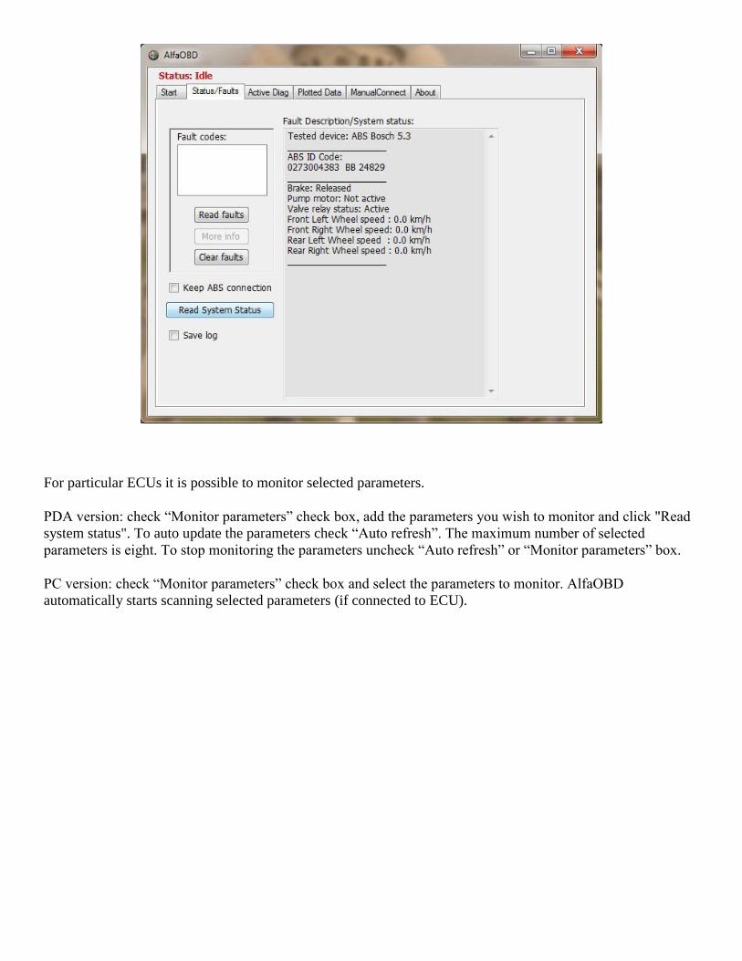
For particular ECUs it is possible to monitor selected parameters.
PDA version: check “Monitor parameters” check box, add the parameters you wish to monitor and click "Read
system status". To auto update the parameters check “Auto refresh”. The maximum number of selected
parameters is eight. To stop monitoring the parameters uncheck “Auto refresh” or “Monitor parameters” box.
PC version: check “Monitor parameters” check box and select the parameters to monitor. AlfaOBD
automatically starts scanning selected parameters (if connected to ECU).
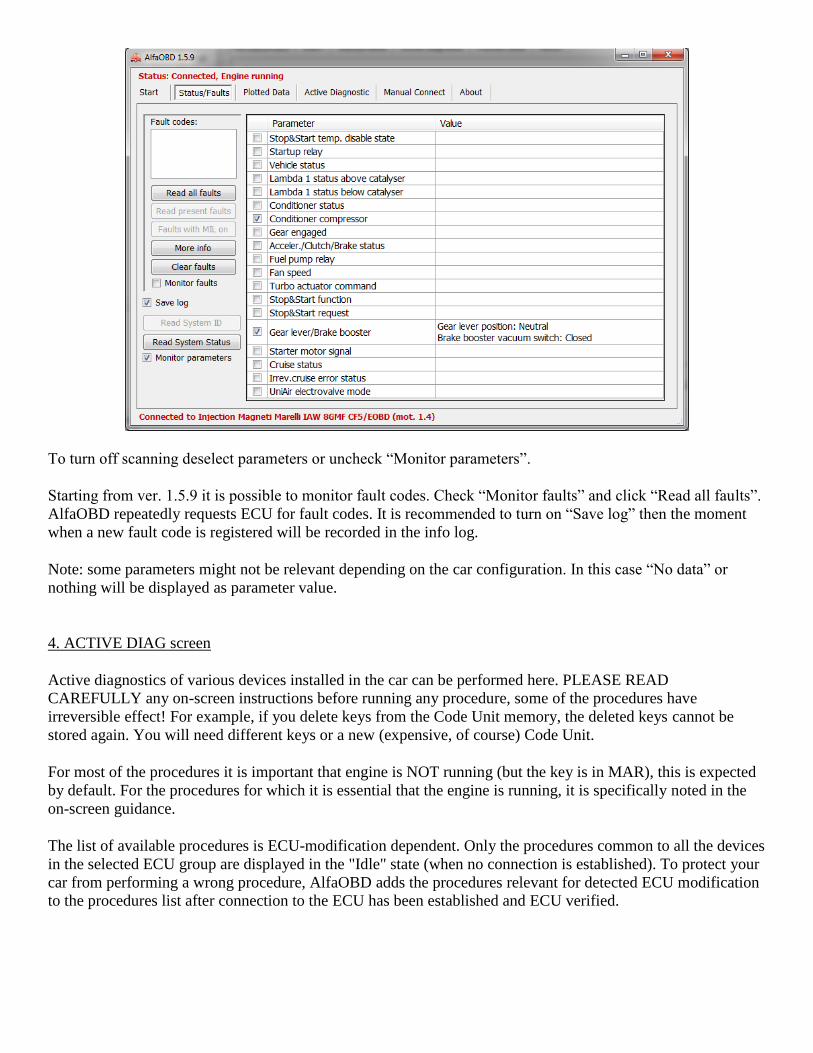
To turn off scanning deselect parameters or uncheck “Monitor parameters”.
Starting from ver. 1.5.9 it is possible to monitor fault codes. Check “Monitor faults” and click “Read all faults”.
AlfaOBD repeatedly requests ECU for fault codes. It is recommended to turn on “Save log” then the moment
when a new fault code is registered will be recorded in the info log.
Note: some parameters might not be relevant depending on the car configuration. In this case “No data” or
nothing will be displayed as parameter value.
4. ACTIVE DIAG screen
Active diagnostics of various devices installed in the car can be performed here. PLEASE READ
CAREFULLY any on-screen instructions before running any procedure, some of the procedures have
irreversible effect! For example, if you delete keys from the Code Unit memory, the deleted keys cannot be
stored again. You will need different keys or a new (expensive, of course) Code Unit.
For most of the procedures it is important that engine is NOT running (but the key is in MAR), this is expected
by default. For the procedures for which it is essential that the engine is running, it is specifically noted in the
on-screen guidance.
The list of available procedures is ECU-modification dependent. Only the procedures common to all the devices
in the selected ECU group are displayed in the "Idle" state (when no connection is established). To protect your
car from performing a wrong procedure, AlfaOBD adds the procedures relevant for detected ECU modification
to the procedures list after connection to the ECU has been established and ECU verified.
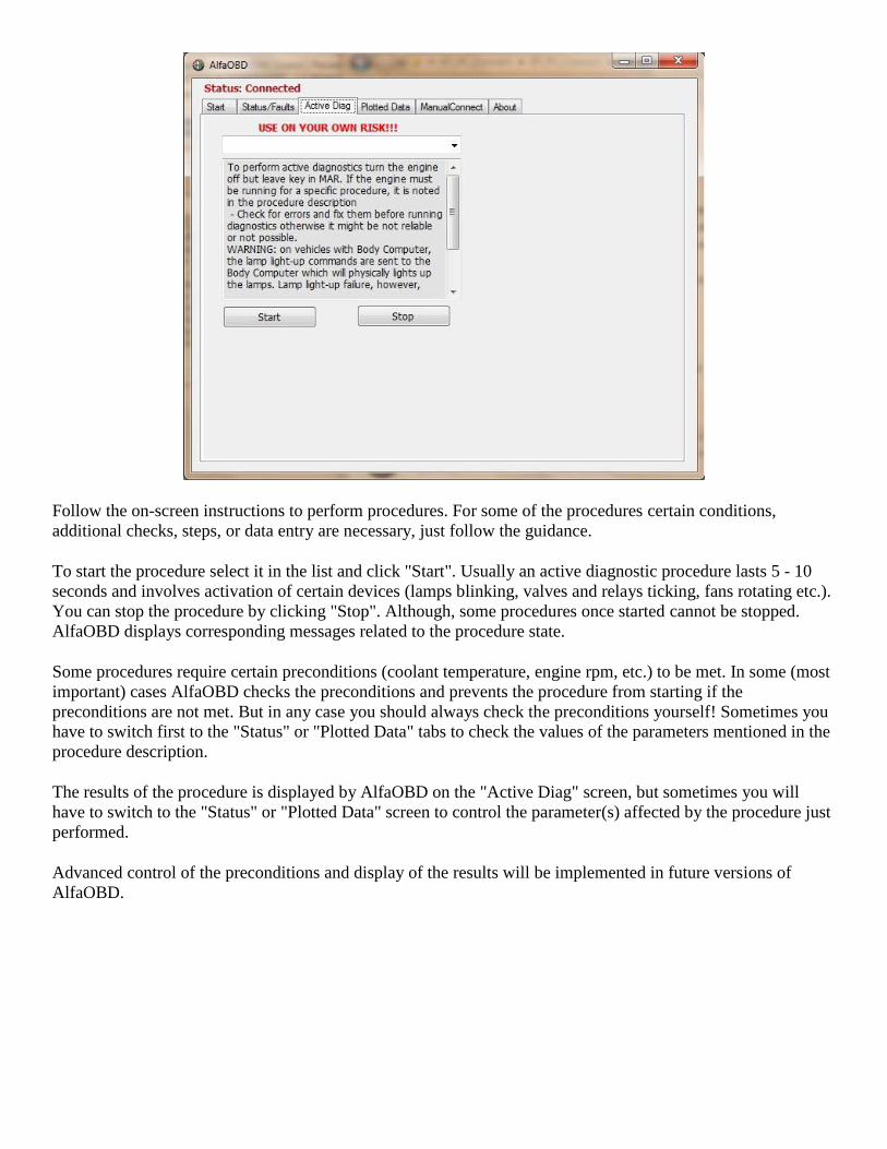
Follow the on-screen instructions to perform procedures. For some of the procedures certain conditions,
additional checks, steps, or data entry are necessary, just follow the guidance.
To start the procedure select it in the list and click "Start". Usually an active diagnostic procedure lasts 5 - 10
seconds and involves activation of certain devices (lamps blinking, valves and relays ticking, fans rotating etc.).
You can stop the procedure by clicking "Stop". Although, some procedures once started cannot be stopped.
AlfaOBD displays corresponding messages related to the procedure state.
Some procedures require certain preconditions (coolant temperature, engine rpm, etc.) to be met. In some (most
important) cases AlfaOBD checks the preconditions and prevents the procedure from starting if the
preconditions are not met. But in any case you should always check the preconditions yourself! Sometimes you
have to switch first to the "Status" or "Plotted Data" tabs to check the values of the parameters mentioned in the
procedure description.
The results of the procedure is displayed by AlfaOBD on the "Active Diag" screen, but sometimes you will
have to switch to the "Status" or "Plotted Data" screen to control the parameter(s) affected by the procedure just
performed.
Advanced control of the preconditions and display of the results will be implemented in future versions of
AlfaOBD.
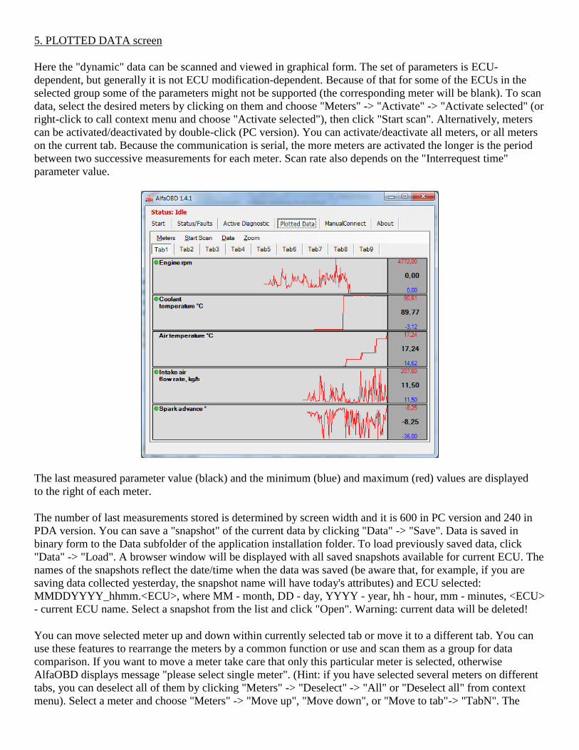
5. PLOTTED DATA screen
Here the "dynamic" data can be scanned and viewed in graphical form. The set of parameters is ECU-
dependent, but generally it is not ECU modification-dependent. Because of that for some of the ECUs in the
selected group some of the parameters might not be supported (the corresponding meter will be blank). To scan
data, select the desired meters by clicking on them and choose "Meters" -> "Activate" -> "Activate selected" (or
right-click to call context menu and choose "Activate selected"), then click "Start scan". Alternatively, meters
can be activated/deactivated by double-click (PC version). You can activate/deactivate all meters, or all meters
on the current tab. Because the communication is serial, the more meters are activated the longer is the period
between two successive measurements for each meter. Scan rate also depends on the "Interrequest time"
parameter value.
The last measured parameter value (black) and the minimum (blue) and maximum (red) values are displayed
to the right of each meter.
The number of last measurements stored is determined by screen width and it is 600 in PC version and 240 in
PDA version. You can save a "snapshot" of the current data by clicking "Data" -> "Save". Data is saved in
binary form to the Data subfolder of the application installation folder. To load previously saved data, click
"Data" -> "Load". A browser window will be displayed with all saved snapshots available for current ECU. The
names of the snapshots reflect the date/time when the data was saved (be aware that, for example, if you are
saving data collected yesterday, the snapshot name will have today's attributes) and ECU selected:
MMDDYYYY_hhmm.<ECU>, where MM - month, DD - day, YYYY - year, hh - hour, mm - minutes, <ECU>
- current ECU name. Select a snapshot from the list and click "Open". Warning: current data will be deleted!
You can move selected meter up and down within currently selected tab or move it to a different tab. You can
use these features to rearrange the meters by a common function or use and scan them as a group for data
comparison. If you want to move a meter take care that only this particular meter is selected, otherwise
AlfaOBD displays message "please select single meter". (Hint: if you have selected several meters on different
tabs, you can deselect all of them by clicking "Meters" -> "Deselect" -> "All" or "Deselect all" from context
menu). Select a meter and choose "Meters" -> "Move up", "Move down", or "Move to tab"-> "TabN". The
maximum number of meters on a tab is 7 for PC version and 6 for PDA version. You cannot move a meter to a
target tab which has maximum number of meters already, first move a meter from the target tab someplace else.
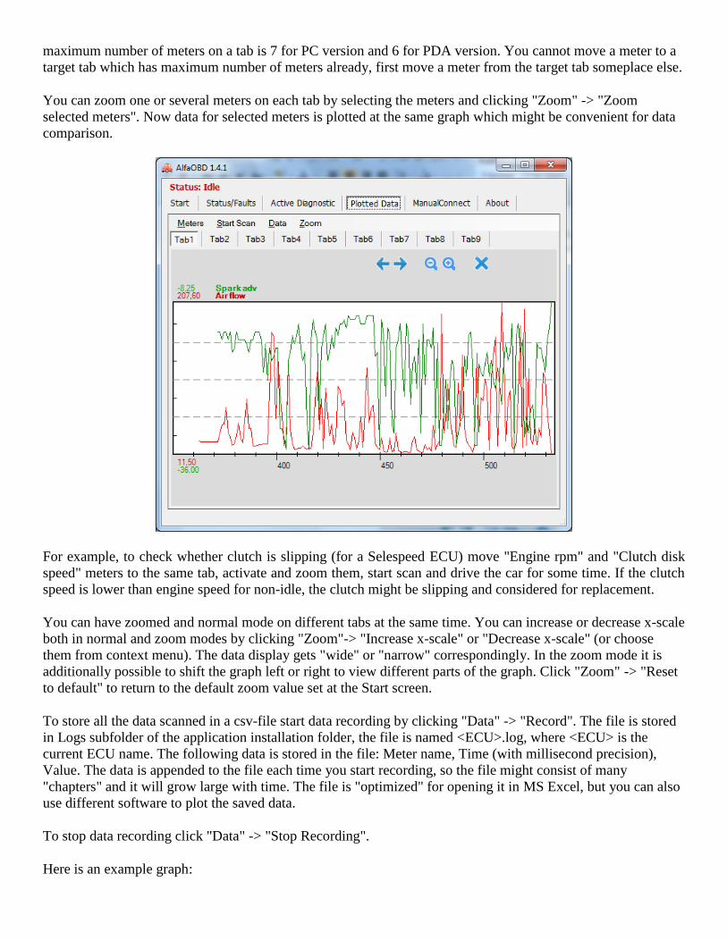
You can zoom one or several meters on each tab by selecting the meters and clicking "Zoom" -> "Zoom
selected meters". Now data for selected meters is plotted at the same graph which might be convenient for data
comparison.
For example, to check whether clutch is slipping (for a Selespeed ECU) move "Engine rpm" and "Clutch disk
speed" meters to the same tab, activate and zoom them, start scan and drive the car for some time. If the clutch
speed is lower than engine speed for non-idle, the clutch might be slipping and considered for replacement.
You can have zoomed and normal mode on different tabs at the same time. You can increase or decrease x-scale
both in normal and zoom modes by clicking "Zoom"-> "Increase x-scale" or "Decrease x-scale" (or choose
them from context menu). The data display gets "wide" or "narrow" correspondingly. In the zoom mode it is
additionally possible to shift the graph left or right to view different parts of the graph. Click "Zoom" -> "Reset
to default" to return to the default zoom value set at the Start screen.
To store all the data scanned in a csv-file start data recording by clicking "Data" -> "Record". The file is stored
in Logs subfolder of the application installation folder, the file is named <ECU>.log, where <ECU> is the
current ECU name. The following data is stored in the file: Meter name, Time (with millisecond precision),
Value. The data is appended to the file each time you start recording, so the file might consist of many
"chapters" and it will grow large with time. The file is "optimized" for opening it in MS Excel, but you can also
use different software to plot the saved data.
To stop data recording click "Data" -> "Stop Recording".
Here is an example graph:
6. MANUAL CONNECT screen
This screen is a kind of communication terminal and can be of use for advanced users. The communication
between AlfaOBD and selected ECU is presented in a "raw" here. You can send commands to the interface (if
using OBDKey/ELM327) and/or to the ECU.
Be careful using this functionality, you can damage the car by sending a wrong command!
First, start the communication by choosing init mode and click "Init". Typically, KWP2000-based ECUs
support fast and slow init, ISO9141-based ones only support slow init. "Fast 200" and "Fast 10400" options are
only relevant for a KLLine interface, any of these options can be chosen for OBDKey or ELM327 interface.
The difference between these options is that for the first one the init procedure includes switching the baud rate
to 200bps first and than to 10400bps, while the second one uses 10400bps throughout the init. ISO9141-based
units are not supported by ELM327 interface. For the CAN-based units choose a corresponding BCAN or
CCAN init.
"Tester present" check box controls whether "keep alive" messages are sent to ECU after communication has
been established. If it is checked the “keep alives” are sent. If it is unchecked the established communication is
not automatically kept and it times out eventually.
"Response Off" check box controls the display of the ECU response to "keep alive" messages. If it is checked
no response to "keep alive" is displayed.
"Echo On" controls display of the echo received from the interface (mostly related to KLLine one). If the box is
checked the echo is displayed together with the ECU response.
"Clear terminal" clears content of the Terminal window.

"Char" and "Hex" option box control how the data exchange is interpreted in the "Terminal" window, and in the
"Send command" box. If "Hex" is checked, the data displayed in hexadecimal form as it is received by software.
This option generally should be selected for KLLine interface. If "Char" option is selected, the data is displayed
in ASCII form, which is relevant for OBDKey interface.
"Send command" box. Here you enter commands to send to the ECU and the interface.
WARNING: you must know exactly what you are doing to not damage your car!
To get a hint for using this functionality, click "Send" with the "Send command" box empty:
"Read Faults" and "Clear Faults" buttons suggest the commands to send to ECU to read and clear faults
correspondingly. Suggestions are done considering selected ECU group. Commands displayed in the "Send
command" box do not include header and CRC bytes defined by the communication protocol. To send the
commands in a correct form do not clear the "Header" and "CRC byte" check boxes. The ECU responses to the
commands will be displayed "as is" in the "Terminal" window, so you will need some knowledge of the
communication protocol to interpret them.
Generally, you do not need to clear the "Header" and "CRC byte" check boxes, because AlfaOBD automatically
calculates the header and CRC for you depending on the chosen ECU. If you clear the checkboxes, you have to
add the header bytes and the checksum byte yourself to the command to send.
Click "Disconnect" to terminate connection.
"Close Port" button closes and opens the selected communication port.
7. ABOUT screen
If the application is in demo mode, you can find the license request code here:
Copy license request and send it to [email protected] to obtain unlock. Alternatively, click "Save To File" to
save the request into LicenseRequest.txt file in the application installation folder. After an activation code is
received paste it to the corresponding filed on the screen and click “Activate”.
MEASURED PARAMETERS DESCRIPTION
ABS
ENGINE TORQUE: driving torque applied to the vehicle wheels
BRAKE CONTACT 2: position of the brake pedal determined from the secondary brake contact
LATERAL ACCELERATION: lateral acceleration of the vehicle in m/sec2
YAW: alterations in the vehicle position
AIRBAG
Notes to the errors reported :
- Errors cannot be deleted with the data written in the crash memory
- If the error is 'Control unit - Internal errors', replace the airbag control unit
- If the error is 'Control unit – Pretensioners and Airbag impact data', replace the airbag control unit
- Replace the airbag control unit if the error is 'Control unit - Pretensioner impact data' and the 'Pretensioner
intervention' parameter shows a value equal to or greater than 3, if less replace the pretensioner explosive
charges
- Replace the airbag control unit if the error is 'Control unit - Side Airbag impact data' and the 'Driver's Side
Airbag or Right or Left Passenger Side Airbag intervention' parameter shows a value equal to or greater than 3
AUTOMATIC GEARBOX
BRAKE SWITCH: brake pedal contact used to handle the engine speed during slow-down
CALCULATED GEARBOX OIL PRESSURE: hydraulic pressure on automatic gearbox clutches and brakes
determined by the control unit
CLUTCH SOLENOID CURRENT: current in mA consumed by the clutch pressure control solenoid.
GEARBOX INPUT REVS: phonic wheel rpm at the gearbox input
GEARBOX OUTPUT REVS: phonic wheel rpm at the gearbox output
E/G SOLENOID COMMAND: ON means that E/G solenoid activation is requested
E/G SOLENOID STATUS: status of the E/G solenoid received by the automatic gearbox control unit
ENGINE TORQUE: driving torque applied to vehicle wheels
GEARBOX OIL PRESSURE: oil pressure inside the automatic transmission torque converter
GEARBOX OIL TEMPERATURE: temperature of the oil in the electro-hydraulic unit
HYDRAULIC CIRCUIT SOLENOID CURRENT: current in mA consumed by the solenoid controlling the
gearbox hydraulic circuit throttle
KEY LOCK SOLENOID: can have the status 'Driven' or 'Not driven', when 'Driven' the key cannot be taken
out
KICK-DOWN FUNCTION: if requested, gear speed engagement will take place at maximum engine speed and
gear reduction strategy will be activated to give extra acceleration
LEVER RELEASE SOLENOID: can have the status 'Driven' or 'Not driven', when 'Driven' it permits gear
lever release
LEVER SIGNAL: actual position of the gearshift lever: PA and A ON = P; A and B ON = R; B and PA ON =
N; B and C ON = D
LOCK-UP SOLENOID VALVE: status of the Lock-up Solenoid valve, 'Driven' or 'Not driven'.
LOCK-UP SOLENOID CURRENT: current consumed by the lock-up clutch control solenoid in mA.
LOCK-UP SOLENOID COMMAND: ON means the request has been made to activate the Lock-up solenoid to
lock the torque converter
PRESSURE REGULATORS 1 - 4: intensity of the current in the regulator, it may vary between 159 mA
(regulator rest position) and 768 mA
SEQUENCE EV 1...6: status of the sequence electrovalves altering the speed ratio.
SOLENOID VALVE 1-2/3-4 COMMAND: ON means solenoid 1-2/3-4 activation has been requested
SOLENOID 1-2/3-4 STATUS: the status of the solenoid 1-2/3-4 received by the automatic gearbox control unit
TORQUE CONVERTER: it hydraulically transmits the power from the engine to the gearbox. It can be 'Closed'
(lock-up clutch engaged) eliminating sliding between pump and turbine, and 'Regulated' (lock-up clutch
modulated) when slipping between pump and turbine is controlled during gear changes
TORQUE TO APPLY: torque set by the electronic control unit
TORQUE REDUCTION: reduces the engine torque to a suitable level during gear changes to make the gear
change smooth
CLIMATE
SUNSHINE SENSOR: thermal energy on the windscreen
TREATED TEMPERATURE 1: temperature of the air coming out of the front foot well vents
TREATED TEMPERATURE 2: temperature of the air coming out of the front, centre and side outlets
ALARM VAS97
TILT SENSOR SIGNAL: the input status of this sensor
EXTERNAL VOLUMETRIC SENSORS SIGNAL: the input status of the sensors
LAST ALARM: the cause of the last alarm indication (siren) that occurred with the system in the surveillance
mode
EMERGENCY KEY ALARMS: the number of alarms caused by the cutting of the cables connecting the
emergency key and the control unit when the system is in the surveillance mode
KEY IN MAR ALARMS: the number of alarms caused by the key being positioned on MAR with the system in
the surveillance mode
+30 AND CABLES CUT ALARMS: the number of alarms caused by the alarm control unit power supply
cables being cut when the system is in the surveillance mode
ENABLINGS MADE: the number of times the system has been enabled in the surveillance mode
VOLUMETRIC SENSORS ENABLE: shows whether the volumetric sensors have been disabled by turning the
ignition key
TILT SENSOR: shows whether the tilt sensor is present in the system, or whether it is connected directly to the
control unit, or located in the ceiling lamp
VOLUMETRIC SENSORS: shows whether the volumetric sensors are present in the system, or whether they
are connected directly to the control unit, or located in the ceiling lamp
TILT SENSOR ENABLE: shows whether the tilt sensor has been disabled by turning the ignition key
NUMBER OF ALARMS: the number of alarms caused by the corresponding unit when the system is in the
surveillance mode
DOOR LOCK VAS 97
HAZARD LIGHTS CONTROL: shows whether the blinker lights control in the receiver is activated
SYSTEM STATUS: shows whether the system is in the "alarm" or the "door lock only" configuration
RECEIVER STATUS: shows whether the receiver is virgin or has already been programmed (at least one
remote control code stored)
COMMUNICATION WITH ALARM CONTROL UNIT: shows whether an alarm control unit responds to the
command during the receiver configuration phase
VOLUMETRIC SENSORS: shows whether the volumetric sensors are present in the receiver
TILT SENSORS: shows whether the tilt sensor is present in the receiver
ELECTRONIC KEY CODE 2 BOSCH/MARELLI/DELPHI
KEY DELETED: the key inserted in the ignition switch has been deleted from the control unit memory and
cannot be stored again
KEY FAULTY OR ABSENT: the key inserted in the ignition switch contains faulty transponder or has no
transponder, or the aerial is not positioned correctly
KEY NOT STORED: the key inserted in the ignition switch has valid transponder but not stored in unit
memory
KEY NOT VALID: the key inserted in the ignition switch does not have a transponder or the transponder is not
valid, or the aerial is not positioned correctly on the ignition switch, or aerial is faulty
KEY STORED: the key inserted in the ignition switch is stored in the control unit and allows engine startup
NO KEY: the key inserted in the ignition switch has no transponder or the transponder is not valid, or the aerial
is not positioned correctly on the ignition switch
KEY STATUS: can have the following statuses:
- stored - the key is recognized by the electronic key control unit and engine start-up is allowed
- not stored - the key is NOT recognized by the electronic key control unit and engine start-up is NOT allowed
- not valid - faulty transponder in the key in the ignition switch; the connection between the electronic key
control unit and the aerial is faulty; the aerial is not positioned correctly on the ignition switch; the aerial is
faulty
- not available - no data available because the key is positioned on Stop, or the keys have not been stored yet
SERIAL LINE CODE REQUEST NOT RECEIVED: the engine control unit has not made the code request.
Wiring between Code Control Unit and Engine Control Unit is in open circuit or Engine Control Unit faulty.
ENGINE (PETROL)
ABSOLUTE THROTTLE VALVE POSITION: throttle valve real position
ACCELERATOR DIGITAL SIGNAL: digital decoding of the analog level of the control unit input signal
ADVANCE REDUCTION FOR KNOCK: reduction of the spark advance actuated after measuring of the
knock
AIR PRESSURE CALCULATED: air pressure in the intake manifold calculated basing on the engine revs and
throttle angle data
AIR FLOW METER VOLTAGE: air flow meter voltage in Volts.
AIR FLOW RATE: amount of air consumed by the engine
AIR FLOW - THROTTLE CLOSED: the air flow through the air flow meter when the throttle is closed
ATMOSPHERIC PRESSURE: the atmospheric pressure read by the pressure sensor
CLIMATE CONTROL IDLE OPENING: the value of the throttle opening at idle due to engine self-adaptation
with the climate control operating
COIL CHARGE TIME: the time setting made by the control unit (in milliseconds), which is necessary to
charge the high tension coils in relation to the variations in the engine parameters when moving.
CRUISE SWITCH: can be 'On' or 'Off', when 'On' the cruise speed set by the driver will be maintained
automatically
CRUISE RESTORE BUTTON (RCL): when pressed it will return the vehicle to the last speed stored by the
Cruise Control
CONDITIONER ACTIVATION REQUEST: the conditioner compressor activation request
CUT-OFF STATUS: shows whether Cut-off is in progress
DTV FACTOR 1 and 2: addition factor to correct the amount of petrol injected. Compensates for the production
tolerances in the air flow meter/lambda sensor/injectors when the engine is idling
ENGINE LOAD ms: basic injection time (without corrections relating to temperature and engine parameters)
ENGINE LOAD %: the quantity of air in the cylinders in relation to maximum filling (unitary displacement)
given in percentage; it is calculated on the basis of the signal coming from the air flow meter (kg/h of air) and
the engine revs signal. The parameter is only relevant when the engine is running.
EVAPORATION CONTROL VALVE: can be 'Active' or 'Not active'. When 'Active' can recover the
hydrocarbon vapors emitted by the tank
EVAPORATION CONTROL VALVE OPENING: percentage of the evaporation control valve opening
FRA SELF-ADAPTION PARAMETER: self-adaption level of the control unit shown as a percentage of the
injection time
FUEL PRESSURE CALCULATED: the pressure calculated for the high pressure circuit by the control unit
FUEL PRESSURE MEASURED: the pressure read inside the high pressure circuit
FUEL PRESSURE SENSOR VOLTAGE: the voltage on the fuel pressure sensor in the high pressure circuit
read by the control unit (about 0.49 Volt at 0 bar, 4.50 Volt at 140 bar)
IDLE POSITION LEARNT: position of the throttle potentiometer recognized by the control unit as 'IDLE' .
IDLE ADJUSTMENT: 'ACTIVE' means the throttle is fully closed and the idle step motor has to be driven by
the control unit
IDLE CONTROL LOWER LIMIT: lower limit value recognized by the control unit as the idle opening
minimum
IDLE CONTROL SELF-ADAPTION: throttle opening value caused by the engine self-adaption
IDLE RECOGNITION TEST: automatic calibration operation of the idle actuator performed by the control unit
IDLE RECOGNITION SIGNALS: synchronization between the two tracks of the idle actuator potentiometer
INJECTION TIME: injector or injectors opening time
INTAKE PRESSURE: the pressure in the intake manifold
IRREV. CRUISE ERROR STATUS: lists the causes of the cruise inhibition. To re-enable the cruise function
turn the key to 'stop', wait 30 sec, turn key to MAR and enable the cruise function
LAMBDA SENSOR 1 UPSTREAM: lambda sensor can have the following statuses:
- open loop (for example with key ON, or in CUT-OFF)
- closed loop (operating at idle or choked)
- semi-closed loop (operating in the transients or at full load)
LAMBDA 1 UPSTREAM/DOWNSTREAM DIAGNOSIS: the lambda sensor diagnosis can have the following
statuses:
- sensor not operating (e.g. at key ON)
- lean (at normal operation in cut-off or the sensor is in open circuit or grounded)
- rich (at normal operation or the sensor is in short circuit to the ‘+’ battery)
- abnormally lean (the sensor is in open circuit or grounded and the sensor status is OPEN LOOOP)
- abnormally rich (the sensor is in short circuit to ‘+’ battery and the sensor status is OPEN LOOP)
LAMBDA SENSOR CONTROL: shows whether the minimum and maximum signal voltage of the lambda
sensor(s) upstream of the catalyser are within the pre-determined limits
LAMBDA SENSOR CORRECTION: the percentage of the injection time correction to keep the strength at the
correct level
LAMBDA SENSOR HEATER: operating status of the lambda sensor heater
LAMBDA SENSOR INTEGRATOR: correction to the amount of fuel made by the control unit to obtain the
correct air/fuel ratio.
LAMBDA SENSOR STATUS: shows whether the sensor is working (closed loop) or not (open loop)
LAMBDA SENSOR VOLTAGE: voltage applied to the lambda heater to keep the sensor at the temperature of
about 780C. The voltage range is 0 to 12 Volts and it varies to keep the sensor temperature
LAMBDA THRESHOLD: shows whether the mixture strength is rich or lean
MAX SPEED TIME COUNTER: total time in seconds the engine has been run at maximal speed
MINIMUM THROTTLE LIMIT: lower limit value recognized by the control unit as the minimum one
MIXTURE PREPARATION MODE: the engine can run in two mixture modes:
- Homogeneous. There is stoichiometric air/petrol mixture in the cylinder at the moment of ignition (14.6),
which homogenously surrounds the spark plug.
- Stratified. There is rich mixture near the spark plug electrodes which becomes increasingly leaner when
measured from the centre to the edge of the combustion chamber. The charge (air/petrol ratio between 17.5 and
21.5) is stratified by injecting the fuel during the compression stroke with the valves closed. The stratified
mixture preparation mode is used at idle and below 1200 rpm under low engine load, and it is advantageous in
terms of consumption and combustion stability. The change from homogenous to stratified mode can only be
made if the engine coolant temperature is >-10C and 5-25 sec after startup. If startup takes place when the
engine coolant temperature is between 15 and 30C (emissions test), the engine works in the homogeneous mode
for about 60 sec. The stoichiometric combustion ensures more rapid and efficient warm-up of the catalytic body
OIL PRESSURE SWITCH: 'ON' means that the oil pressure sufficient for engine operation has been reached
OVERBOOST PRESSURE MEASURED: the pressure measured in the overboost circuit
PHASE VARIATOR: operating status of the phase variator
PHONIC WHEEL LEARNING: shows whether the phonic wheel learning is in progress, has been performed,
or whether the engine is off
PRESSURE REGULATOR OPENING: the percentage of the fuel pressure regulator opening relating to the
high pressure circuit
PRESSURE SWITCH (TRINARY): shows activation of the air conditioner pressure switch activating the fan
(or fans) at speed 1
PRESSURE SWITCH (QUADRINARY): shows activation of the air conditioner pressure switch activating the
fan (or fans) at speed 2
QUADRINARY 1st LEVEL: shows activation of the air conditioner pressure switch that activates the fans at
the 1st speed
QUADRINARY 2nd LEVEL: shows activation of the air conditioner pressure switch that activates the fans at
the 2nd speed
RECOVERY (THROTTLE ERROR): shows whether recovery resulting from a throttle error is in progress, and
specifies whether it is a torque limiting or a rev limiting recovery, or whether the DCMOTOR (motorized
throttle) is off
RELATIVE THROTTLE VALVE POSITION: throttle valve position minus the basic (minimum) opening
value
SET CRUISE ACCELER.(+): can be 'Requested' or 'Not requested', when 'Requested' the vehicle speed set in
the Cruise Control can be increased
SET CRUISE DECELER.(-): can be 'Requested' or 'Not requested', when 'Requested' the vehicle speed set in
the Cruise Control can be decreased
SPARK ADVANCE: advance value assigned by the control unit without considering the value of precise
mechanical fitting
STRENGTH ADAPTATION: strength adaptation percentage relatively to the engine coolant temperature.
SYNCHRONISATION STATUS: when the key is turned from 'off' to 'on' the 'initialization' status is maintained
shortly, then it changes to the 'awaiting revs' and eventually to the 'awaiting revs/timing' (no crank); if the
engine is started correctly the status is synchronized engine
TARGET OVERBOOST PRESSURE: the overboost pressure calculated by the control unit
TARGET IDLE SPEED: theoretical value set by the control unit for the idle rpm
THEORETICAL LAMBDA TEMPERATURE: temperature of the lambda sensor calculated by the control unit
THROTTLE ANGLE: angular position of the motorized throttle
THROTTLE LEARN: with 'Activated' or 'Deactivated' it shows whether the motorized throttle lower limit has
been learned or not. 'In progress' or 'Not active' shows whether the system is performing self-learning
THROTTLE LEARN PHASE: stage reached in the throttle lower limit value learning procedure. The value
varies between 0 and 3 with the new control unit, and the value varies between 3 and 9 if the lower limit has
already been learnt
THROTTLE LEARNING RESULTS: shows whether the self-learning of the lower limit of the motorized
throttle has been completed correctly
THROTTLE LEARN INHIBIT: shows whether the self-learning of the lower limit of the motorized throttle is
inhibited
THROTTLE LEARN STAGE: shows the stage reached by the throttle lower limit value learn procedure. The
value varies between 0 and 11 for the new control unit. If the lower limit has already been learnt this value is
between 3 and 11.
THROTTLE LEARN STORAGE: shows whether the self-learning of the lower limit of the motorized throttle
has been stored
THROTTLE LOWER LIMIT SELF-LEARN: stage reached in the throttle opening lower limit learning
procedure
THROTTLE POSITION TRACK 1: percentage value of the motorized throttle signal track 1
THROTTLE OPENING IDLE: shows whether the control unit has recognized the idle position correctly
THROTTLE POSITION TRACK 1: percentage value of the motorized throttle signal track 1
THROTTLE POSITION TRACK 2: percentage value of the motorized throttle signal track 2
THROTTLE VALVE POSITION: angular position of the throttle valve
TARGET THROTTLE POSITION (CRUISE): the position the throttle has to keep to maintain the speed set by
the cruise control
TARGET THROTTLE OPENING: value of the throttle opening referred by the control unit for correct engine
management
TRA SELF-ADAPTION PARAMETER: injection time of self-adaption level of the control unit in
microseconds
TURBO ACTUATOR CONTROL: value in % of the duty cycle of the waste gate valve control
WATER TEMPERATURE RECOVERY: default value used by the control unit if the coolant temperature
sensor is faulty
ENGINE (DIESEL)
AD/C ACCELERATOR POSITION 1: the voltage read on track 1 of the accelerator potentiometer
AD/C ACCELERATOR POSITION 2: the voltage read on track 2 of the accelerator potentiometer
AD/C AIR FLOW METER VOLTAGE: the voltage read directly on the sensor
AD/C AIR MASS: the voltage on the air mass meter (air flow meter)
AD/C BATTERY VOLTAGE: battery voltage read directly on the control unit power supply
AD/C DIESEL PRESSURE: the voltage read directly on the sensor
AD/C DIESEL TEMPERATURE: the voltage read directly on the diesel temperature sensor
AD/C THROTTLE POSITION: throttle position read directly on the sensor
AD/C OVERBOOST PRESSURE: the voltage read directly on the sensor
AD/C WATER TEMPERATURE: the voltage read directly on the water temperature sensor
AIR CONTROL INHIBIT: the causes for the air control inhibition by the EGR (Exhaust Gas Recirculation)
AIR MASS MEASURED: amount of air measured by the air flow meter
AIR TEMPERATURE: the temperature of the air taken into the intake manifold
AIR TEMPERATURE (AIR FLOW METER): the air temperature measured by the digital air flow meter
AIR TEMPERATURE (TURBO): the air temperature read inside the turbo sensor
ASYNCHRONOUS INJECTION: injection occurs without considering the top dead centre synchronization
AVERAGE DISTANCE BETWEEN LAST REGENERATIONS: the average distance travelled by the vehicle
between consecutive DPF regenerations
AVERAGE DURATION OF LAST REGENERATIONS: the average time spent for the last regenerations of
the particulate filter
AVERAGE TEMPERATURE OF LAST REGENERATIONS: the average temperature of the last
regenerations of the particulate filter
BRAKE BOOSTER VACCUUM SWITCH: the state of the brake booster vacuum contact used to manage the
Stop&Start to ensure safe vehicle braking (CLOSED: 470mbar, OPEN 300mbar)
BRAKE CONTACT 2: the position of the brake pedal picked up from the secondary brake contact
CALCULATED ADVANCE: diesel injection advance with respect to the top dead centre calculated by the
control unit on the basis of the available information acquired
CAPACITOR 1 VOLTAGE: charge voltage of capacitor 1 driving the injectors
CAPACITOR 2 VOLTAGE: charge voltage of capacitor 2 driving the injectors
CLUTCH PEDAL EXTENDED: 'PRESSED' means that the clutch pedal has reached the end of stroke
CONDITIONER ACTIVATION REQUEST: the conditioner compressor activation request
CONDITIONER RELAY COMMAND: the status of the conditioner relay command coming from the control
unit
CRUISE SWITCH: can be 'On' or 'Off', when 'On' the cruise speed set by the driver is maintained automatically
CYLINDER 1/2/3/4 INJECTOR CODES: codes written in EEPROM. They are obtained at the factory by
testing at specific operating points related to particular conditions of fuel pressure and injection time
DIESEL PRESSURE MEASURED: pressure read inside the diesel high pressure circuit
DIESEL QUANTITY: main quantity of diesel injected for the engine load (the quantities relating to the pilot
injector phase and the pre-main injection phase are not included)
DIFFERENTIAL SENSOR PRESSURE: the value of the pressure (in bar) in the particulate filter obtained by
the corresponding sensor
DISTANCE NEXT 'OIL CHANGE': the distance in kilometers to travel till the next oil change
EGR EXCHANGER CUT-OUT VALVE: when ACTIVE it facilitates the engine warm-up as it prevents
recirculation of exhaust gases in the intercooler
EGR MEASURED POSITION: the position assumed by the EGR (Exhaust Gas Recirculation) compared to the
EGR TARGET POSITION. The parameters tend to follow each other, i.e. they should have similar values
EGR TARGET POSITION: the value the EGR actuator must take calculated on the basis of the engine
conditions, i.e. the opening/closing position to obtain lesser or greater recirculation of the exhaust gases
EGR THROTTLE OPENING: throttle control voltage in %
EGR VALVE LEARN: 'ENABLED' means that there are no errors in the EGR system and the learn procedure
will be carried out during the Power latch at the next Key-OFF. If 'DISABLED' the conditions for proceeding
with the learn procedure do not exist as errors could be present in the EGR system
EGR VALVE OPENING: percentage with which the EGR valve is operated
FLOW CHOKE OPENING: the closing percentage of the intake valves (SWIRL)
FUEL CORRECTION CYLINDER 1/2/3/4/5: once any engine malfunctioning has been corrected it indicates
the amount of fuel added/removed to/from each injector to make the various cylinder behave in the same way
FUEL CONSUMPTION: gives the calculated consumption in l/100 km or l/hour
FUEL PUMP RELAY CONTROL: the status of the diesel low pressure fuel pump relay control
GLOW PLUG PREHEATING: 'ACTIVE' means the glow plugs are controlled with the preheating control unit
INJECTION ADVANCE: angular advance of the injector measured by the sensor
INJECTION ADVANCE CORRECTION: correction to the injection advance value set by the control unit
INJECTION PUMP POTENTIOMETER: voltage measured on the accelerator potentiometer in Volts
INJECTION TIME CORRECTION: correction made by the control unit to the basic injection time calculation
IRREV. CRUISE ERROR STATUS: lists all the causes for the cruise function inhibition. To re-enable the
cruise function, turn the key to stop, wait 30 sec, turn it to MAR and enable the cruise function
KM WITH WATER TEMPERATURE WARNING LAMP ON: the total distance travelled since the water
temperature warning lamp has been lit up
KM WITH WATER IN DIESEL WARNING LAMP ON: the total distance travelled since the Water in diesel
warning lamp has been lit up
LAMBDA OXYGEN CONCENTRATION: the value of the lambda sensor strength, ranges between 0% and
21%
LAST DPF REPLACEMENT ODOMETER: distance in km travelled since the last replacement of the
particulate filter. When the 'particulate filter replacement' procedure has been performed this parameter is set to
0 km. If the engine control unit has been replaced the contents of the parameter are updated with the same value
as the LAST ECU REPLACEMENT ODOMETER parameter
LAST ECU REPLACEMENT ODOMETER: distance in km travelled by the vehicle. If the engine control unit
is being replaced the parameter is manually set with the corresponding configuration procedure, and it is being
updated from that moment on. To find out the km when the engine control unit was replaced calculate the
difference between this parameter and the Odometer parameter
LAST OIL CHANGE ODOMETER: the odometer value when the oil change procedure has been performed. At
the end of the procedure the number of km travelled by the vehicle is copied into this parameter with the help of
corresponding diagnostic procedure. The value must only be updated after the next procedure is performed
LAST OVERREV ODOMETER: the odometer value when over-revving occurs. This value is overwritten
when over-revving occurs again and it always gives the odometer value relating to the last over-revving. It is
stored in the EEPROM memory and it is handled the same way as the other parameters relating to over-revving.
LAST REGENERATION ODOMETER: this parameter indicates the number of km travelled since the last
particulate filter regeneration (forced and/or spontaneous) and it is set to zero at the end of the last regeneration
completed successfully (spontaneous and/or automatic) or when the particulate filter is replaced. If the engine
control unit is replaced the contents of the parameter are updated with the same value as the LAST ECU
REPLACEMENT ODOMETER.
MAIN INJECTION ADVANCE: degrees of advance with respect to the top dead centre at which the amount of
diesel calculated to keep the needed engine load is injected
MAIN INJECTION START: shows the advance (in degrees) with respect to the top dead centre with which the
amount of diesel calculated for the engine load is injected
MAIN INJECTION TIME: shows the opening time of the injectors according to the amount of diesel calculated
for the engine load
MAX SPEED TIME COUNTER: total time in seconds the engine has been run at maximal speed
NUMBER OF REGENERATIONS INTERRUPTED BY KEY-OFF: shows the number of consecutive
particulate filter regenerations interrupted by the driver with engine switch-off
NUMBER PROGRAMMINGS: the number of times the control unit has been programmed
NUMBER REGENERATIONS SINCE LAST OIL CHANGE: the overall number of particulate filter
regenerations activated by high flow resistance since last oil change
ODOMETER AT LAST PROGRAMMING: mileage in km when control unit has been programmed the last
time
'OIL CHANGE' PROCEDURES NUMBER: increased by one every time the relative oil change procedure is
performed
OIL CHANGE REQUEST ODOMETER: the odometer value at the oil change request done with the
corresponding diagnostic procedure
OIL DEGRADATION INDICATOR: shows how long the engine oil will last. 100% means that the oil change
procedure has been just carried out. This value decreases with the distance travelled by the vehicle, particulate
filter regenerations, etc.
OVERBOOST ADJUSTMENT INHIBIT: recovery values set by the control unit in case the over-boost
pressure control is inhibited
OVERBOOST COUNTER: refers to the time in overpressure on values that are too high. Minimum and
maximum thresholds are related to the turbo. Once the minimum threshold is exceeded the turbo cuts in and the
counter does not increase. Although, once the maximum threshold is exceeded the counter increases. If
OVERBOOST lasts too long (beyond the max. threshold) the diagnostic strategies related to the turbo cut in.
OVERBOOST PRESSURE MEASURED: pressure read in the overboost circuit
OVERBOOST VALVE OPENING: percentage of the overboost pressure modulating valve opening
PARTICULATE FILTER CLOGGING: the calculation of the particulate mass expressed in % according to the
DPF pressure picked up by the sensor connected to the engine control unit. The clogging levels and the
corresponding particulate filter statuses are:
- between 0% and 30% (Particulate filter status: NOT CLOGGED)
- between 30% and 120% (NORMAL CLOGGING)
- between 120% and 200% (FILTER CLOGGED)
- > 200% (TO BE REGENERATED)
PARTICULATE FILTER STATE: the level of clogging of the particulate filter under all conditions.
PARTICULATE FILTER TEMPERATURE: the exhaust gas temperature picked up by the sensor in the
particulate filter input
PILOT INJECTION TIME: opening time of the injectors which is necessary to reduce knock according to the
amount of diesel
PILOT INJECTION START: advance (in degrees) with respect to the top dead centre with which the amount of
diesel necessary to reduce knock is injected
PREHEATING CONTROL UNIT DIAGN: if 'ON' indicates that the glow plug preheating control unit has been
activated
PRE-INJECTION ADVANCE: degrees of advance with respect to the top dead centre at which the amount of
diesel calculated to reduce knock is injected
PRESSURE REGULATOR (IF PRESENT): percentage opening of the diesel pressure regulator relating to the
high pressure circuit
PRESSURE REGULATOR OPENING (DRV): percentage opening of the pressure regulator mounted on the
high pressure pump on the high pressure circuit side or on rail (DRV). The diesel pressure regulator is mounted
on the rail (injector support) only for Fiat Croma & Alfa 159, in the other cars it is mounted on the high
pressure pump (high pressure circuit side)
PRESSURE REGULATOR OPENING (MPROP): the opening percentage of the pressure regulator mounted on
the high pressure pump on the low pressure circuit side
QUANTITY DIESEL FOR CRUISE: quantity of diesel used to keep the vehicle speed set by the cruise control
QUANTITY DIESEL PILOT INJECTION: quantity of diesel injected during the pilot injection
REAL ADVANCE: diesel injection advance with respect to the top dead centre that has been set effectively
REQUEST FROM CRUISE LEVER: the request on the cruise lever (No request, Cruise restore button (RCL),
Set Cruise deceleration (-), Set Cruise acceleration (+)
RESISTANCE TO FLOW IN THE DPF: the momentary value of the resistance to the exhaust gases flow in the
particulate filter
SPEED LIMIT (FROM PROXI): displays the legal speed limit factory-set in the control unit. If the value is 255
km/h the vehicle has no legal speed limit and it can be limited with the corresponding configuration procedure.
If the value is not 255 km/h it can not be modified as the vehicle is limited in compliance with the legal
requirements
SPEED LIMIT: displays the vehicle speed limit set in the control unit
STARTER MOTOR SIGNAL: 'HIGH' means that the injection control unit requests starter motor activation.
STOP&START ENABLE FROM NBC: the state of the command from the body computer control unit. 'OFF'
summarizes all the conditions that cause failure to stop the engine when the vehicle is stationary
STOP&START FUNCTION: 'not permitted' means that engine startup has been requested but it is not allowed
due to wrong conditions
STOP&START FUNCTION REQUEST: the Stop&Start function enable/disable has been requested from the
body computer control unit by pushing the pushbutton.
STOP&START TEMPORARILY DISABLED STATE: the causes for the Stop&Start function to be
temporarily inhibited.
TARGET AIR MASS: the amount of air calculated by the control unit according to the parameters read by the
sensors
TARGET CRUISE SPEED: the value the cruise control refers to for keeping the cruise speed
TARGET DIESEL PRESSURE: pressure calculated by the control unit and estimated inside the diesel high
pressure circuit
TARGET OVERBOOST PRESSURE: pressure calculated by the control unit
THROTTLE SOLENOID VALVE OPENING: shows the opening percentage of the throttle on the intake duct
(5% = throttle open, 95% = throttle closed)
TOTAL NUMBER OF REGENERATIONS: the overall number of particulate filter regenerations activated for
any reason
TOTAL QUANTITY DIESEL: the total amount of diesel injected
TRAVELLED WITH DPF WARNING LAMP ON: the total distance travelled since the particulate filter
warning lamp has been lit up
TURBO 1 COMMAND: the % of the duty cycle of the VGT (Variable Geometry Turbocharger) valve
command, or the waste gate valve, or the small low-speeds turbo (version with double turbo)
TURBO 2 COMMAND: the % of the duty cycle of the large high-speeds turbo (version with double turbo)
TURBO MEASURED POSITION: shows the position taken by the variable geometry turbo compared to the
TURBO TARGET POSITION. The parameters should have similar values
TURBO TARGET POSITION: the value the turbo actuator must assume on the basis of the torque request
conditions, i.e. the position of the blades to obtain supercharging pressure
TYPE OF GEARBOX PRESENT: shows the type of the gearbox installed in the vehicle. The state 'Not
feasible' should only occur if the engine control unit has been exchanged on vehicles with a different type of
transmission, manual and automatic
SELESPEED
BRAKE NODE (NFR): the presence of ABS/VDC/ASR (only if connected to CAN) is 'LEARNT' when at least
one message is received on CAN
BRAKE PEDAL: shows whether the brake pedal is 'Pressed', 'Released' or gives 'Error on switch' if there is a
malfunction
CITY REQUEST (IF PRESENT): shows the 'Pressed' or 'Released' status of the 'City' button (automatic mode,
in which the gears are changed by the selespeed)
CLUTCH DEGRADATION INDEX: The degradation index indicates how much torque the clutch can
transmit. It varies from -4000 to +14000:
- Negative value: the clutch can transmit more torque if the material of that particular clutch disc is subjected to
special thermal conditions
- Positive value very high : the clutch transmits less than the normal torque. The clutch is worn, or overheated,
or the clutch surface is dirty (oil, etc.)
CLUTCH DISK SPEED: rotation speed of the clutch disk
CLUTCH PRESSURE PLATE STROKE: position of the clutch actuator as mm of piston stroke
CLUTCH PRESSURE PLATE REFERENCE: position of the clutch actuator set by the electronic control unit
(has no meaning if the clutch is not driven)
CLUTCH SOLENOID CURRENT: current in mA consumed by the clutch pressure control solenoid
CLUTCH SOLENOID VALVE CURRENT: current passing through the solenoid valve controlling the clutch
pressure plate
CLUTCH SV CURRENT: the current passing through the solenoid valve controlling the clutch pressure plate
CLUTCH TEMPERATURE: temperature reached by the clutch disk
ECO/SPORT REQUEST: the 'Pressed' or 'Released' status of the 'ECO' button (Economy mode, consumption
optimization function) or the 'SPORT' button, the function making the gear changes more 'sporty'
EFFECTIVE TORQUE: the torque applied to the clutch disk
ENGAGEMENT POSITION: position of the gearbox engagement fork in mm
EVEN SPEED CURRENT: current passing through the solenoid valve for even speed engagement
GEARBOX/CLUTCH SELF-CALIBRATION: results of the last 'self-calibration end of line/service' procedure
performed. It can be: Correct, Error selection 1st-2nd, Error selection 5th-R, Error selection 3rd-4th, Error
engaging 1st, Error engaging 2nd, Error engaging 3rd, Error engaging 4th, Error engaging 5th, Error engaging
R, Error positioning of gear engaging actuator, clutch closed operation interrupted, operation interrupted due to
absence of general conditions, Error clutch plunger adjustment, Error clutch valve self-calibration
GEARBOX OIL TEMPERATURE: the temperature of the gearbox oil. It is calculated by the selespeed control
unit on the basis of the water temperature parameter received from the CAN line
GEARSHIFT LEVER POSITION: the position of the gearshift lever: 'No request', 'Lever forwards', 'Lever
back', 'Lever in neutral', 'Lever in reverse' and Autom./City req. (AUTOM.: the gears are changed directly by
selespeed and not by the driver, CITY REQ.: Economy mode, consumption optimization function)
HIGH SPEED SELECTION: a high speed has been requested
HYDRAULIC CIRCUIT PRESSURE: pressure in the hydraulic circuit inside the actuator group
HYDRAULIC CIRCUIT SOLENOID CURRENT: current in mA consumed by the solenoid controlling the
gearbox hydraulic circuit throttle
LH BUTTON: the 'Pressed' or 'Released' status of the left button on the steering wheel
ODD SPEED CURRENT: current passing through the solenoid valve for odd speed engagement
OVERTEMPERATURE TIME: total time the clutch was in over-temperature
RETRY COUNTER: the total number of times (for all gears) the gearbox has tried to reengage a gear (e.g. in
case of sticking)
RH BUTTON: the 'Pressed' or 'Released' status of the right button on the steering wheel
SELECTION POSITION: position of the gearbox shaft in mm
SELF-CALIBRATED CLUTCH CLOSED POSITION: position of the clutch actuator in mm self-calibrated by
the electronic control unit
SELF-CALIBRATED CLUTCH SLIP START POSITION DELTA: the difference (in mm) between the self-
calibrated clutch closed position and the clutch position at which torque is being transmitted (connects engine
and wheels)
SOLENOID VALVE ON/OFF: ON activates the Lock-up clutch, OFF activates the hydraulic unit forwards-
backwards
SOLENOID VALVE NO FLOW CURRENT: current corresponding to 'No flow' in the clutch solenoid valve
SPEED ENGAGED: the speed engaged by the system
SPEED REQUESTED: the speed requested by the driver
STARTUP ENABLE RELAY: shows whether all the conditions necessary to enable vehicle startup are present
SV NO FLOW CURRENT: current corresponding to 'No flow' in the clutch solenoid valve
TORQUE TO APPLY: the torque set by the electronic control unit
BODY COMPUTER
CODE TYPE: shows whether code has been 'Programmed by FIAT' or 'Programmed by Spare Parts' if it has
already been replaced. If it is 'Programmed by Supplier' the tables of the Code codes and/or RF codes may not
have been unloaded (Body control unit programming incomplete), this is only valid for vehicles with Passive
Entry (Easy-Go).
ENGINE CONTROL UNIT: can have the statuses 'Programmed' or 'Virgin'. If virgin, the Body control unit
must also be virgin, otherwise there will be an error on the transponder message line.
CODE: it can have the statuses of 'Programmed' or 'Virgin'. If virgin the Engine Control unit must also be
virgin otherwise it means that the Body Control unit has not received the 'end of transmission' from the engine
control unit.
CODE REQUEST FROM ENGINE ECU: shows whether the Immo-code request has been made by the engine
control unit to the body computer after the Key-on.
CODE STATUS BYTE: hexadecimal numbers which should be provided to the Fiat help desk if some keys
have not been programmed correctly.
ALARM MODE: if the alarm is present, the parameter shows what Country mode the alarm operates in, if only
the RF receiver is present it shows 'Alarm inhibited' . The mode can be changed for the preselected country only
if alarm is present.
LAST CAUSE FOR SHUTDOWN INHIBITION FROM STOP&START: shows the last cause or causes that
have not allowed the engine shutdown by the Stop&Start system. The parameter is associated with the
'Shutdown inhibition from Stop&Start counters' parameter.
LAST CAUSE FOR FORCED STARTUP FROM STOP&START: shows the last cause or causes that forced
engine startup by the Stop&Start system. The parameter is associated with the 'Forced startup from Stop&Start
counters' parameter.
LAST CAUSE FOR STARTUP INHIBITION FROM STOP&START: shows the last cause or causes that have
not allowed engine startup by the Stop&Start system. The parameter is associated with the 'Startup inhibition
from Stop&Start counters' parameter.
SHUTDOWN INHIBITION FROM STOP&START STATES: shows if there are states currently that do not
allow the engine shutdown by the Stop&Start system.
FORCED STARTUP FROM STOP&START STATES: shows if there are states currently that force engine
startup by the Stop&Start system.
STARTUP INHIBITION FROM STOP&START STATES: shows if there are states currently that do not allow
the engine startup by the Stop&Start system.
TEG CONTROL
BODY COMPUTER FROM CAN: if 'Virgin' it means that the Body Computer control unit has not been
programmed correctly. If it is not possible to obtain the 'Key on Mar' state it might mean that the Body control
unit needs to be replaced with a correctly programmed one.
MINICRYPT FROM STEERING LOCK (NBS): if 'Not valid' there is a Minicrypt error in the Steering Lock
control unit. If it is not possible to obtain the 'Key on Mar' state it might be necessary to replace this control
unit.
MINICRYPT RECEIVED FROM BODY: if 'Not valid' there may be an alignment problem with the Body

control unit.
TRANSPONDER PROGRAMMED/PROGRAMMABLE/DISABLED: shows whether the TEG has been
programmed, or whether it is suitable for the control unit but it has not been programmed yet, or whether it has
been previously deleted from memory.
TEG IDENTIFICATION: shows whether the TEG belongs to this control unit (e.g.: a disabled or
programmable TEG)
TEG AUTHENTICATION: shows whether the TEG has a secret code that is suitable for this control unit (e.g.:
a programmed or programmable TEG).