Embed Size (px)
Citation preview
1
Internet QoS
• Goal of QoS architecture:
To provide some level of predictability and control beyond the current IP best-effort ser
vice.• The challenge of these IP QoS technologies is :
to provide differentiated delivery services for individual flows or aggregate wi
thout breaking the Internet in the process.
2
Why use Quality of Service?
• The Internet is being driven by rich media types, convergence of computer, communications broadcast, and telephony industries.
• Today’s Internet provides a best-effort service to all of its application.– Do not make any promises about the Quality of Service
(QoS) – The public Internet does not allow delay-sensitive multi
media applications (ex:IP telephone) to request any special treatment.
3
QoS technologies
• Resource reservation (integrated services):– Allocate resources on a per-flow basis
• A “flow” is equivalent to the five-tuple (transport protocol, source address&port, destination address and port)
• Prioritization (differentiated services):– Network traffic is classified and apportioned network re
sources according to bandwidth management policy criteria.
4
Integrated Services
• RFC1633
• Network resources are apportioned according to an application’s QoS request The Intserv architecture defines two major classes of service :– Guaranteed Quality of Service– Controlled Load Network Service
5
Key features of Intserv
• Resource reservation• Call setup• Traffic characterization and specification of the de
sired QoS• Signaling for call setup• Per-element call admission
6
Resource reservation
• A router is required to maintain enough state to know what amounts of its resources (buffers, link bandwidth ) are already committed to on-going sessions.
7
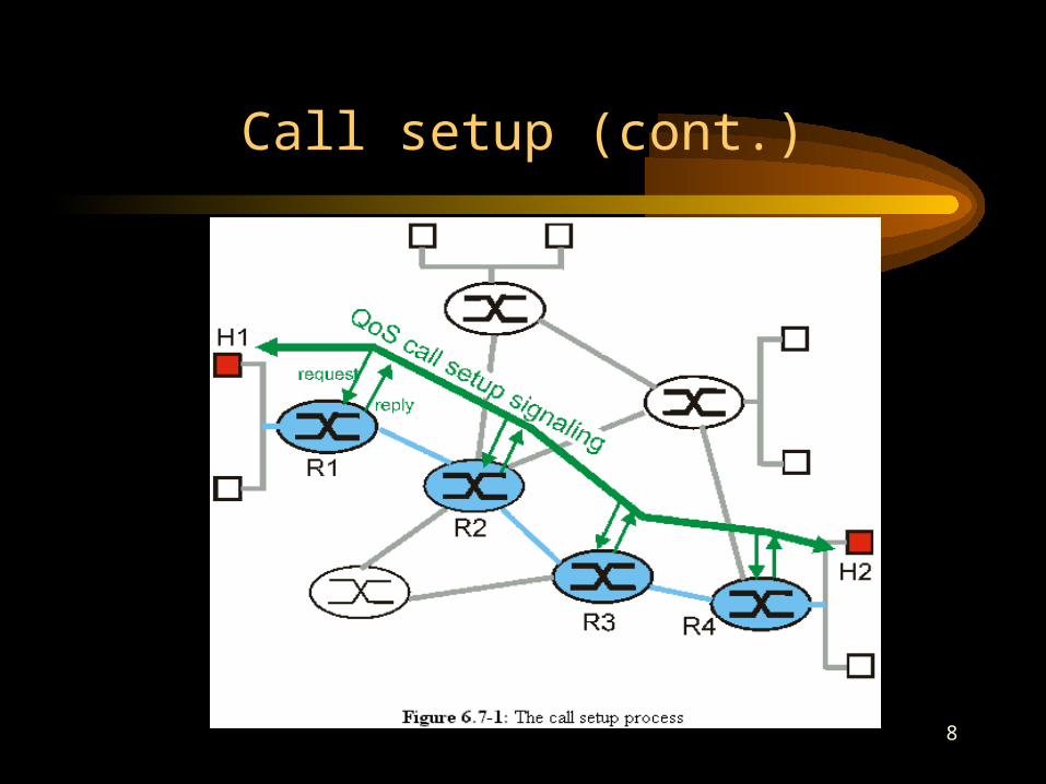
Call setup
• A session requiring QoS guarantees must first be able to reserve sufficient resources at each network router on its source-to-destination path.
• Call setup process requires the participation of each router on the path.– Determine the local resources required by the session
– Consider the amounts of its resources that are already committed to other on-going session
– Determine whether it has sufficient resources to satisfy the per-hop QoS requirement of the session at this router without violating QoS
8
Call setup (cont.)
9
Traffic characterization and specification of the desired QoS
• Rspec (R for reserved)– Rspec defines the specific QoS being requested by a co
nnection
• Tspec (T for traffic)– Tspec characterizes the traffic the sender will be sendin
g into the network, or the receiver will be receiving from the network.
10
Signaling for call setup
• A session’s Tspec and Rspec must be carried to the routers at which resources will be reserved for the session.
• RSVP protocol is currently envisioned as the signaling protocol.
11
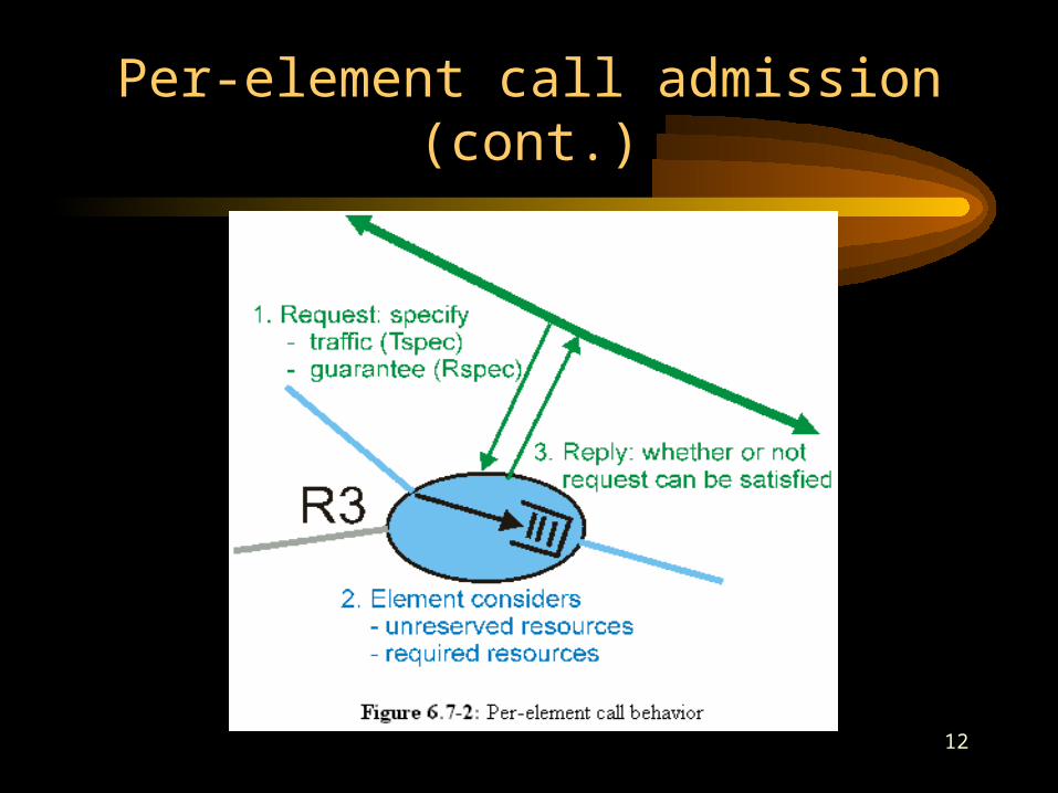
Per-element call admission
• While receiving the Tspec and Rspec for a session requesting a QoS guarantee, it can determine whether or not it can admit the call.
• The call admission decision depends on:– The traffic specification
– The requested type of service
– The existing resource commitments already made by the router to on-going sessions
12
Per-element call admission (cont.)
13
Controlled Load Network Service
• RFC2211
• Providing the client data flow with quality of service closely approximation the QoS that same flow would receive from an unloaded network element
• Using capacity (admission) control to assure that this service is received even when the network element is overloaded.
• Applications:
– Adaptive real-time applications
– These applications perform quite well when the network is unloaded, but rapidly degrade in performance as the network becomes more loaded
14
Controlled Load Network Service (cont.)
• Controlled-load service simply prioritizes the packets in the flow, ensuring that they do not wait too long in router queues as they cross the network.
15
Guaranteed Quality of Service
• RFC2212• Providing firm bounds on the queueing delays that
a packet will experience in a router.• Applications:
– Hard real-time applications
– Audio and video playback applications that are intolerant of late-arriving packets
16
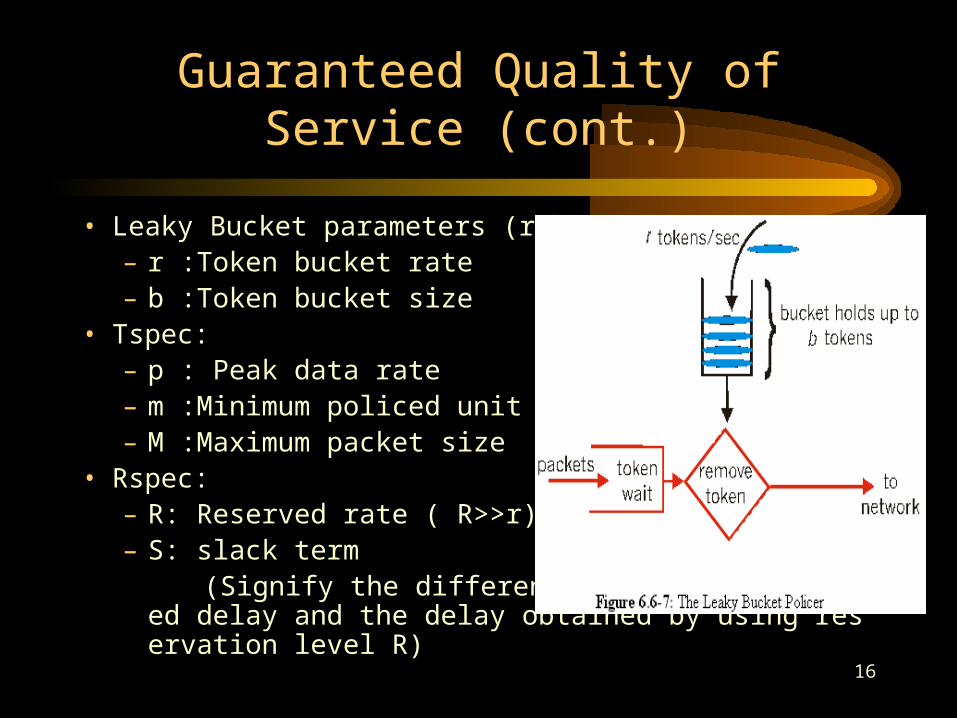
Guaranteed Quality of Service (cont.)
• Leaky Bucket parameters (r,b)– r :Token bucket rate – b :Token bucket size
• Tspec:– p : Peak data rate– m :Minimum policed unit– M :Maximum packet size
• Rspec:– R: Reserved rate ( R>>r)– S: slack term (Signify the difference between the desired delay and the d
elay obtained by using reservation level R)
17
Guaranteed Quality of Service (cont.)
• Simple Delay bound : b/R– Request guarantee transmission rate is R– The amount of traffic generated over interval t i
s bounded by rt+b– The maximum queueing delay experienced by a
ny packet will be bound by b/R
18
Introduction of RSVP• Resource ReSerVation Protocol. • Allows applications running in hosts to reserve res
ources in the Internet for their data flows.• Used by the routers to forward bandwidth reservat
ion requests.• RSVP software must be present in the receivers, s
ender, and routers.
19
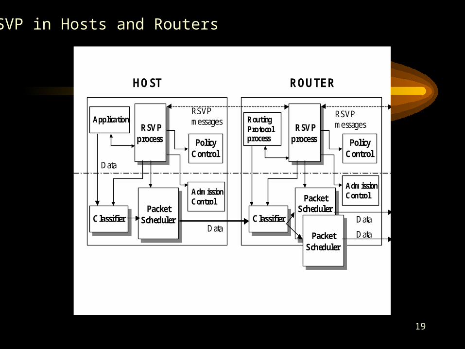
RSVPprocess
PacketScheduler
AdmissionControl
PolicyControl
Classifier
Application RSVPprocess
PacketScheduler
AdmissionControl
PolicyControl
Classifier
RoutingProtocolprocess
Data
PacketScheduler
DataData
Data
RSVPmessages
RSVPmessages
HOST ROUTER
RSVP in Hosts and Routers
20
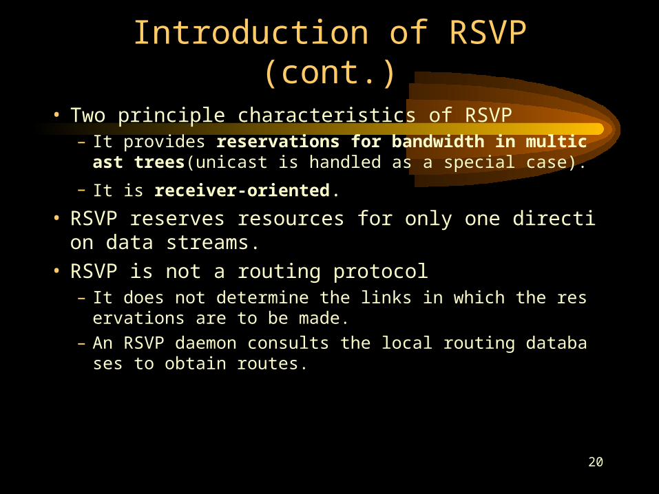
Introduction of RSVP (cont.)• Two principle characteristics of RSVP
– It provides reservations for bandwidth in multicast trees(unicast is handled as a special case).
– It is receiver-oriented.• RSVP reserves resources for only one direction data stream
s.• RSVP is not a routing protocol
– It does not determine the links in which the reservations are to be made.
– An RSVP daemon consults the local routing databases to obtain routes.
21
Introduction of RSVP (cont.)• RSVP depends on an underlying routing protocol
(unicast or multicast) to determine the routes for the flows
• RSVP is sometimes referred to as a signaling protocol that allows hosts to establish and tear-down reservations for data flows
22
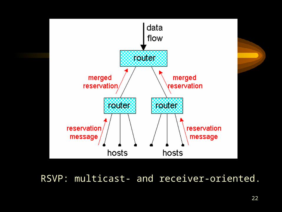
RSVP: multicast- and receiver-oriented.
23
Heterogeneous receivers• Sender does not have to know the receiving rates
of all receivers.• It only needs to know the maximum rate of all its
receivers.• The sender encodes the video or audio into
multiple layers and sends all the layers up to the maximum rate into multicast tree.
• The receivers pick out the layers that are appropriate for their receiving rates.
24
Heterogeneous receivers (cont.)• In order to not excessively waste bandwidth in the
network’s links, the heterogeneous receivers must communicate to the network the rates they can handle.
• RSVP gives foremost attention to the issue of reserving resources for heterogeneous receivers.
25
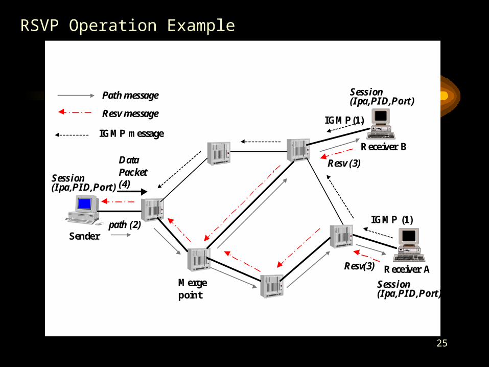
Receiver B
Receiver A
Sender
Session (Ipa,PID,Port)
path (2)
Merge point
Session (Ipa,PID,Port)
Session (Ipa,PID,Port)
IGMP (1)
IGMP(1)
Resv(3)
Resv (3)
Path message
Resv message
IGMP message
DataPacket (4)
RSVP Operation Example
26
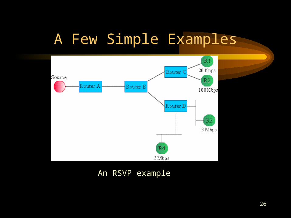
A Few Simple Examples
An RSVP example
27
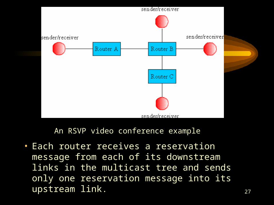
• Each router receives a reservation message from each of its downstream links in the multicast tree and sends only one reservation message into its upstream link.
An RSVP video conference example
28
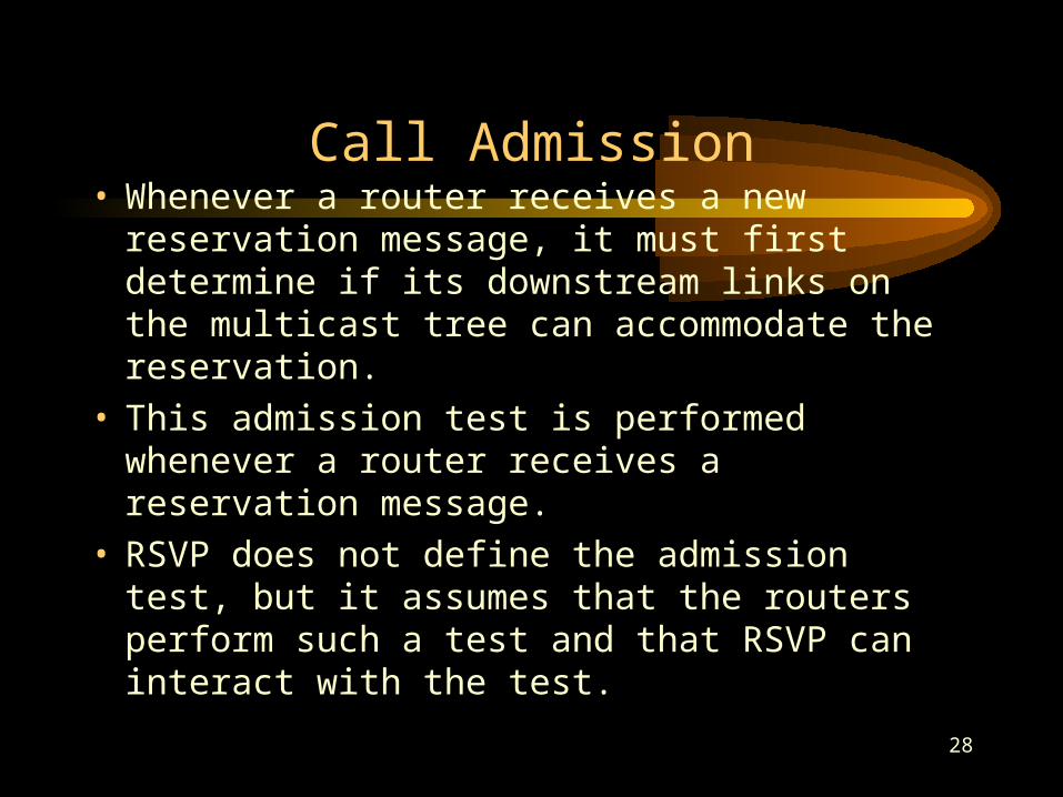
Call Admission• Whenever a router receives a new reservation
message, it must first determine if its downstream links on the multicast tree can accommodate the reservation.
• This admission test is performed whenever a router receives a reservation message.
• RSVP does not define the admission test, but it assumes that the routers perform such a test and that RSVP can interact with the test.
29
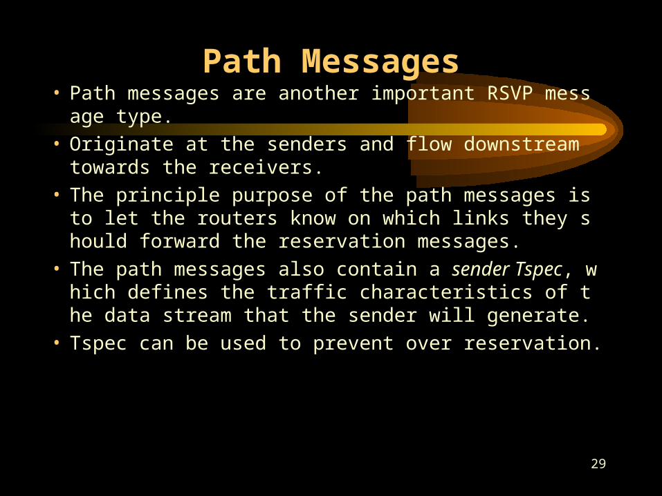
Path Messages• Path messages are another important RSVP message ty
pe.
• Originate at the senders and flow downstream towards the receivers.
• The principle purpose of the path messages is to let the routers know on which links they should forward the reservation messages.
• The path messages also contain a sender Tspec, which defines the traffic characteristics of the data stream that the sender will generate.
• Tspec can be used to prevent over reservation.
30
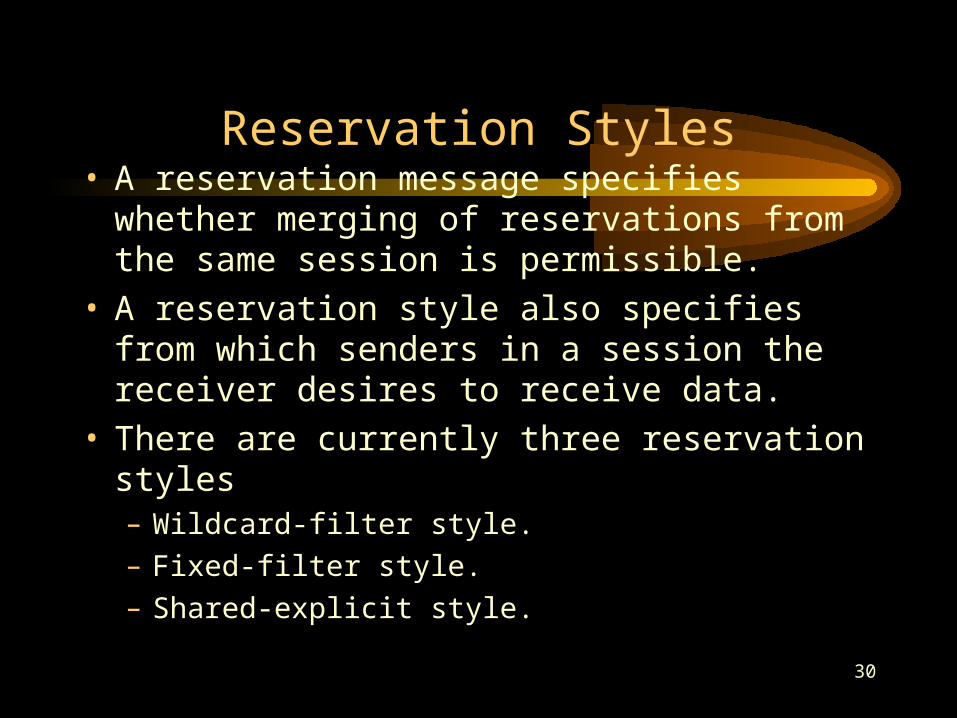
Reservation Styles• A reservation message specifies whether merging
of reservations from the same session is permissible.
• A reservation style also specifies from which senders in a session the receiver desires to receive data.
• There are currently three reservation styles– Wildcard-filter style.
– Fixed-filter style.
– Shared-explicit style.
31
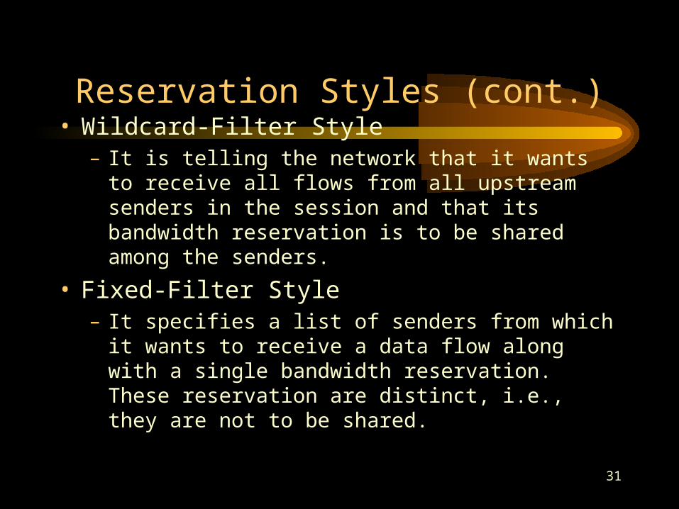
Reservation Styles (cont.)• Wildcard-Filter Style
– It is telling the network that it wants to receive all flows from all upstream senders in the session and that its bandwidth reservation is to be shared among the senders.
• Fixed-Filter Style– It specifies a list of senders from which it wants to
receive a data flow along with a single bandwidth reservation. These reservation are distinct, i.e., they are not to be shared.
32
Reservation Styles (cont.)• Shared-Explicit Style
– It specifies a list of senders from which it wants to receive a data flow along with a single bandwidth reservation. This reservation is to be shared among all the senders in the list.
33
Reservation Styles (cont.)• Shared reservations, created by the wildcard-filter
and the shared-explicit styles, are appropriate for a multicast session whose sources are unlikely to transmit simultaneously .
• The fixed-filter reservation, which creates distinct reservations for the flows from different senders, is appropriate for video teleconferencing.
34
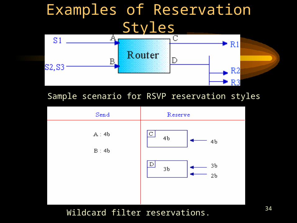
Examples of Reservation Styles
Wildcard filter reservations.
Sample scenario for RSVP reservation styles
35
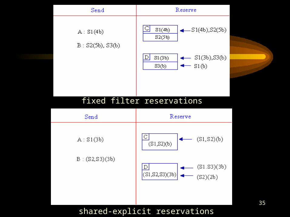
fixed filter reservations
shared-explicit reservations
36
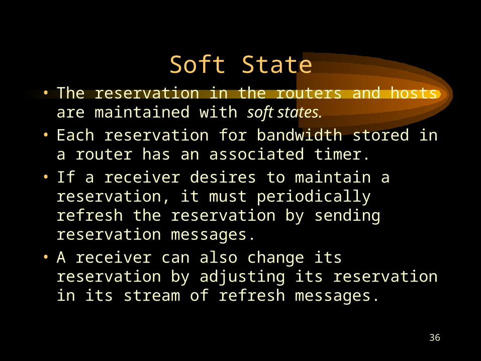
Soft State• The reservation in the routers and hosts are
maintained with soft states.• Each reservation for bandwidth stored in a router
has an associated timer.• If a receiver desires to maintain a reservation, it
must periodically refresh the reservation by sending reservation messages.
• A receiver can also change its reservation by adjusting its reservation in its stream of refresh messages.
37
Soft State (cont.)• The senders must also refresh the path state by
periodically sending path messages.
38
Transport of Reservation Messages• RSVP messages are sent hop-by-hop directly over
IP, thus the RSVP message is placed in the information field of the IP datagram.
• If an RSVP path or reservation message is lost, a replacement refresh message should arrive soon.
39
Insufficient Resource • Because a reservation request that fails an admissi
on test may embody a number of requests merged together, a reservation error must be reported to all the concerned receivers.
• These reservation errors are reported within ResvError messages, then receivers can reduce the amount of resource that they request and try reserving again.
40
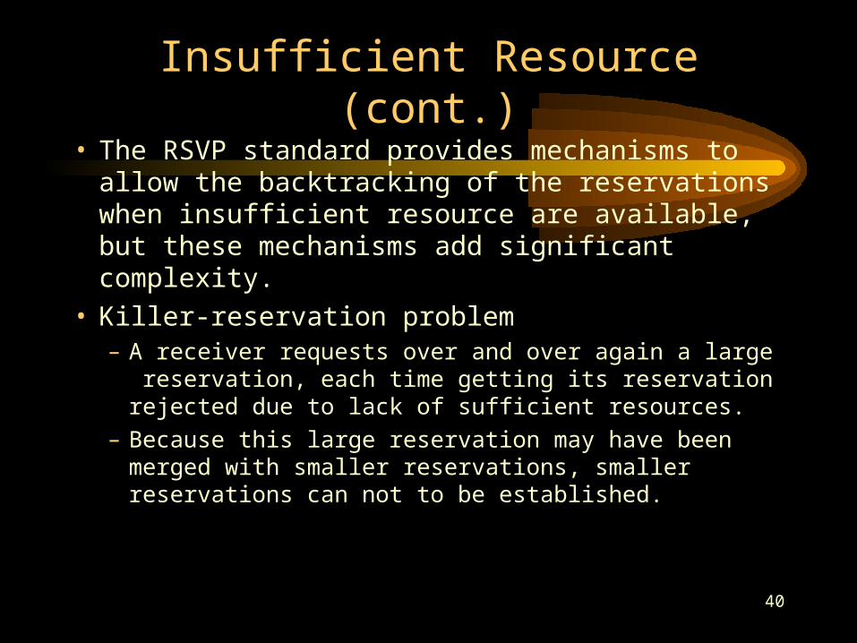
Insufficient Resource (cont.)• The RSVP standard provides mechanisms to allow the
backtracking of the reservations when insufficient resource are available, but these mechanisms add significant complexity.
• Killer-reservation problem – A receiver requests over and over again a large reservation,
each time getting its reservation rejected due to lack of sufficient resources.
– Because this large reservation may have been merged with smaller reservations, smaller reservations can not to be established.
41
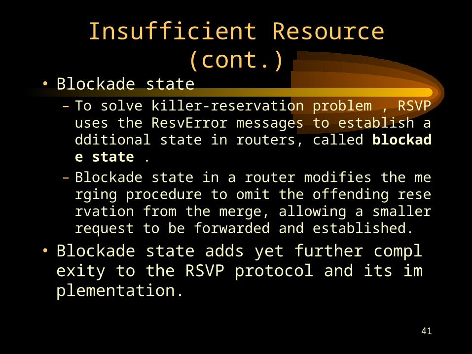
Insufficient Resource (cont.)• Blockade state
– To solve killer-reservation problem , RSVP uses the ResvError messages to establish additional state in routers, called blockade state .
– Blockade state in a router modifies the merging procedure to omit the offending reservation from the merge, allowing a smaller request to be forwarded and established.
• Blockade state adds yet further complexity to the RSVP protocol and its implementation.
42
Disadvantage of RSVP• Need more memory to record per flow state
information of each node in network.• RSVP is lack of scalability.
43
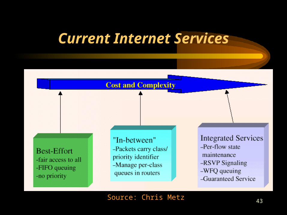
Current Internet Services
Source: Chris MetzSource: Chris Metz
44
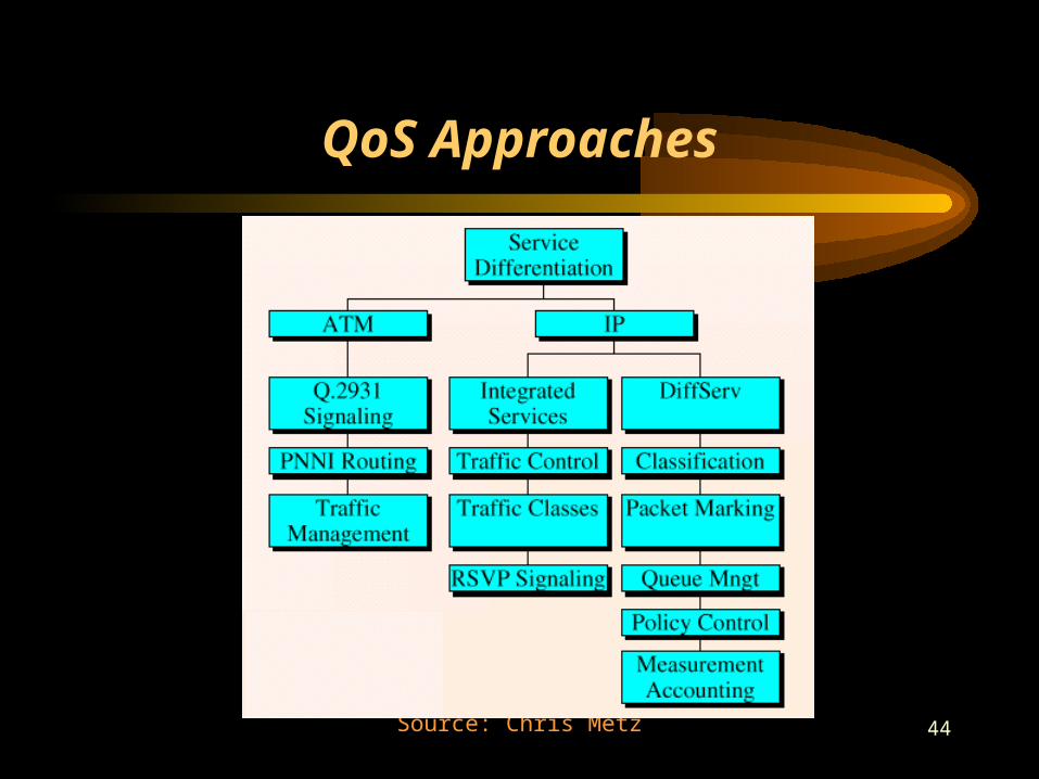
QoS Approaches
Source: Chris MetzSource: Chris Metz
45
Why Differentiated Services?
• For business purpose: – high usage utilization of the resources.
• Simper than IntServ(RSVP):– not keep per-flow state information in each router.– decrease memory requirements.
• More efficient core routers:– limited number of service classes.– simple packet forwarding.
46
Differentiated Services
• DiffServ is an approach to delivering different levels of service in a scalable way.
• It migrates work loading to the edges and boundaries of a DS domain.
• Keep the forwarding simple in the core routers.• It marks packets according to their service requireme
nt (DS codepoint). Based on the mark, core routers apply differentiated per-hop forwarding behavior (PHB).
47
Differentiated Services (cont.)
• Interior nodes in the DS domain only have to deal with the small number of traffic aggregates rather than keeping track of every separate traffic flow that passes through.
48
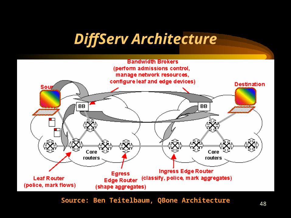
DiffServ Architecture
Source: Ben Teitelbaum, QBone ArchitectureSource: Ben Teitelbaum, QBone Architecture
49
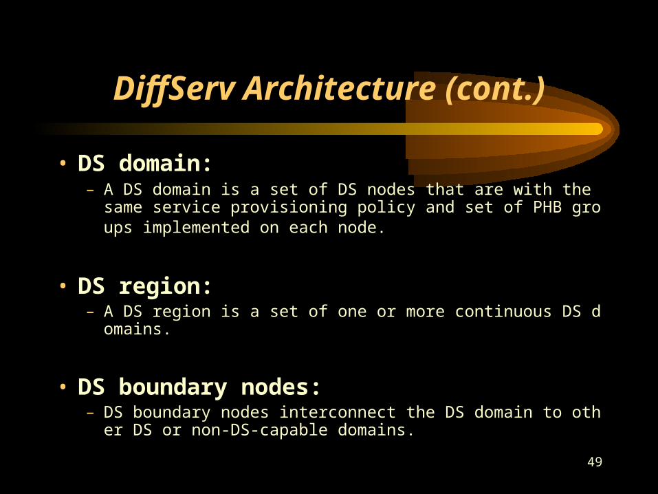
DiffServ Architecture (cont.)
• DS domain:– A DS domain is a set of DS nodes that are with the same ser
vice provisioning policy and set of PHB groups implemented on each node.
• DS region:– A DS region is a set of one or more continuous DS domains.
• DS boundary nodes:– DS boundary nodes interconnect the DS domain to other DS
or non-DS-capable domains.
50
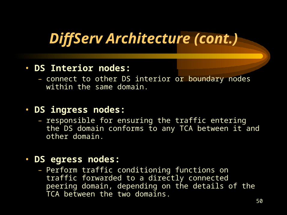
DiffServ Architecture (cont.)
• DS Interior nodes:– connect to other DS interior or boundary nodes within the
same domain.
• DS ingress nodes:– responsible for ensuring the traffic entering the DS domain
conforms to any TCA between it and other domain.
• DS egress nodes:– Perform traffic conditioning functions on traffic forwarded to
a directly connected peering domain, depending on the details of the TCA between the two domains.
51
DiffServ Components
• Classifier.• Traffic Conditioner.• Service Level Agreement (SLA).• Traffic Conditioning Agreement (TCA).
52
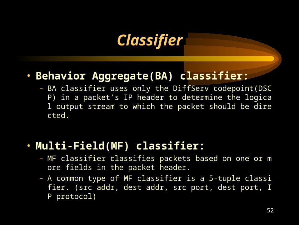
Classifier
• Behavior Aggregate(BA) classifier:– BA classifier uses only the DiffServ codepoint(DSCP) in a pa
cket’s IP header to determine the logical output stream to which the packet should be directed.
• Multi-Field(MF) classifier:– MF classifier classifies packets based on one or more fields i
n the packet header.– A common type of MF classifier is a 5-tuple classifier. (src a
ddr, dest addr, src port, dest port, IP protocol)
53
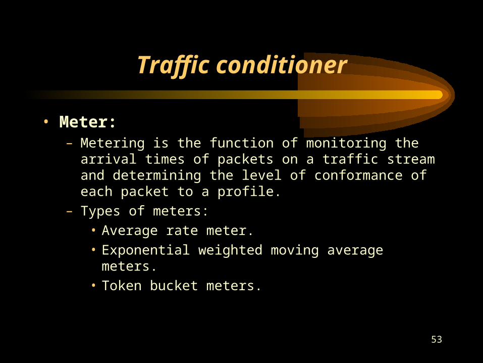
Traffic conditioner
• Meter:– Metering is the function of monitoring the arrival times of
packets on a traffic stream and determining the level of conformance of each packet to a profile.
– Types of meters:• Average rate meter.• Exponential weighted moving average meters.• Token bucket meters.
54
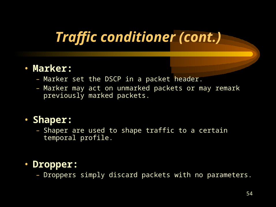
Traffic conditioner (cont.)
• Marker:– Marker set the DSCP in a packet header.– Marker may act on unmarked packets or may remark
previously marked packets.
• Shaper:– Shaper are used to shape traffic to a certain temporal
profile.
• Dropper:– Droppers simply discard packets with no parameters.
55
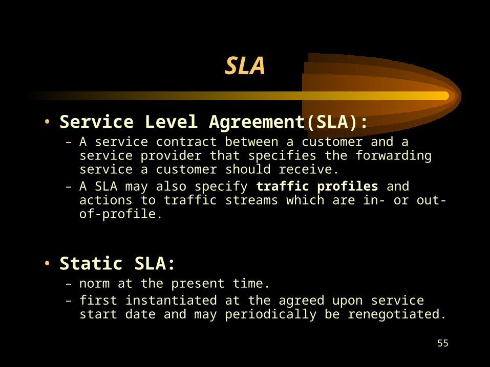
SLA
• Service Level Agreement(SLA):– A service contract between a customer and a service
provider that specifies the forwarding service a customer should receive.
– A SLA may also specify traffic profiles and actions to traffic streams which are in- or out-of-profile.
• Static SLA:– norm at the present time.– first instantiated at the agreed upon service start date and
may periodically be renegotiated.
56
SLA (cont.)
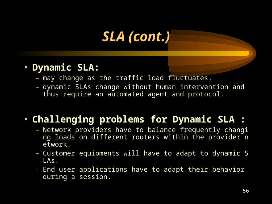
• Dynamic SLA:– may change as the traffic load fluctuates.– dynamic SLAs change without human intervention and thus
require an automated agent and protocol.
• Challenging problems for Dynamic SLA :– Network providers have to balance frequently changing load
s on different routers within the provider network.– Customer equipments will have to adapt to dynamic SLAs.– End user applications have to adapt their behavior during a
session.
57
TCA
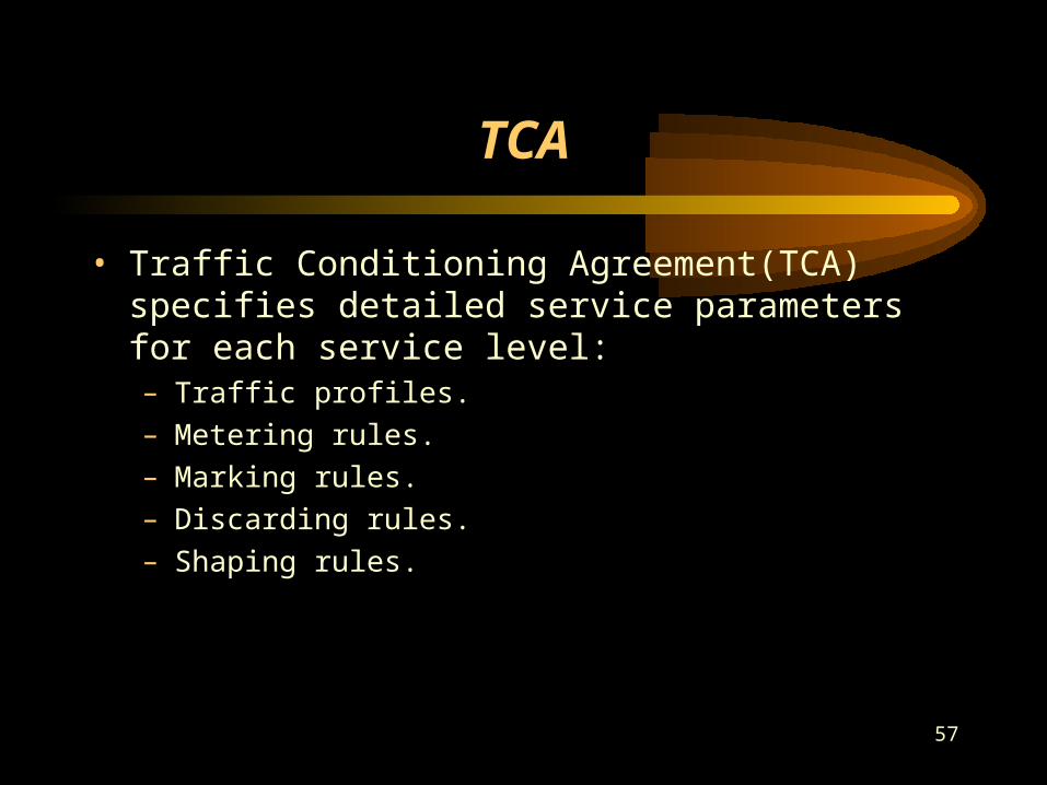
• Traffic Conditioning Agreement(TCA) specifies detailed service parameters for each service level:– Traffic profiles.– Metering rules.– Marking rules.– Discarding rules.– Shaping rules.
58
Traffic Profiles
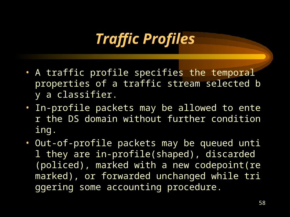
• A traffic profile specifies the temporal properties of a traffic stream selected by a classifier.
• In-profile packets may be allowed to enter the DS domain without further conditioning.
• Out-of-profile packets may be queued until they are in-profile(shaped), discarded(policed), marked with a new codepoint(remarked), or forwarded unchanged while triggering some accounting procedure.
59
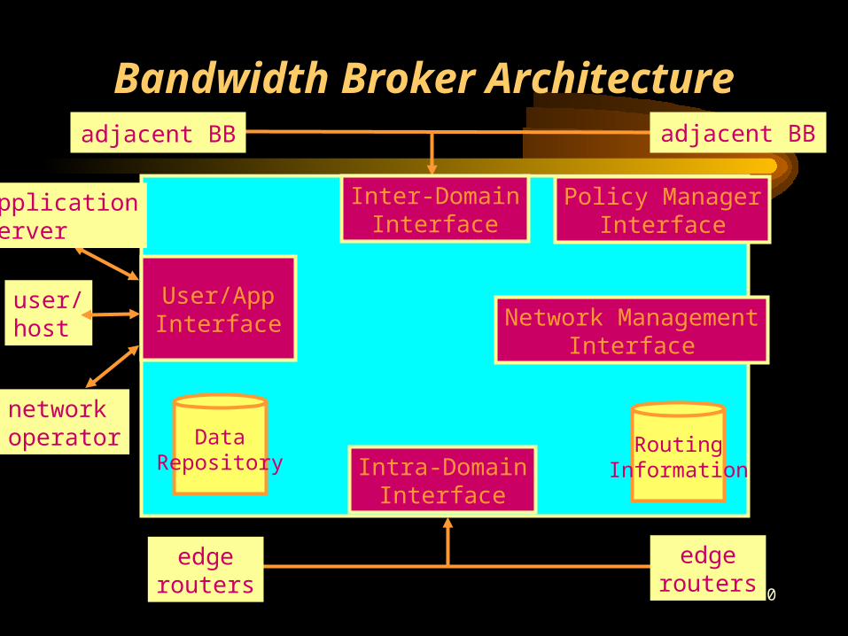
Bandwidth Broker
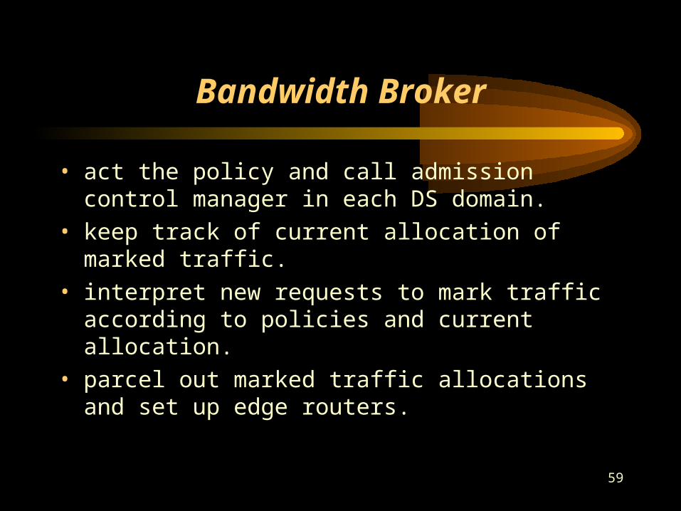
• act the policy and call admission control manager in each DS domain.
• keep track of current allocation of marked traffic.• interpret new requests to mark traffic according to
policies and current allocation.• parcel out marked traffic allocations and set up edge
routers.
60
Bandwidth Broker Architectureadjacent BB adjacent BB
User/AppInterface
applicationserver
user/host
networkoperator
Inter-DomainInterface
Intra-DomainInterface
edgerouters
edgerouters
DataRepository
RoutingInformation
Policy ManagerInterface
Network ManagementInterface
61
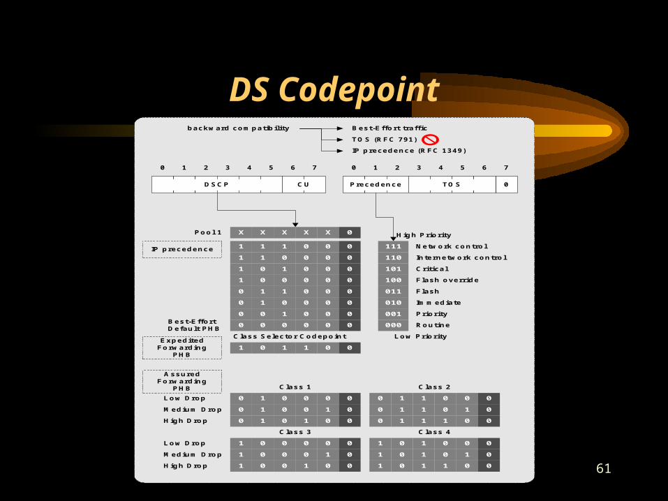
backw ard com patib ility
TO S (R FC 791)
IP precedence (R FC 1349)
0 1 2 3 4 5 6 7
TO S
111 N etw ork contro l
Precedence 0
110 In ternetw ork contro l
101 C ritical
100 Flash override
011 Flash
010 Im m ediate
001 Priority
000 R outine
B est-Effo rt traffic
0 1 2 3 4 5 6 7
D SCP C U
XPool 1 X X X X 0
1 1 1 0 0 0
1 1 0 0 0 0
1 0 1 0 0 0
1 0 0 0 0 0
0 1 1 0 0 0
0 1 0 0 0 0
0 0 1 0 0 0
0 0 0 0 0 0B est-Effo rtD efau lt PH B
C lass Selector C odepo in t
1 0 1 1 0 0
Low Prio rity
H igh Prio rity
0 1 0 0 0 0
0 1 0 0 1 0
0 1 0 1 0 0
0 1 1 0 0 0
0 1 1 0 1 0
0 1 1 1 0 0
1 0 0 0 0 0
1 0 0 0 1 0
1 0 0 1 0 0
1 0 1 0 0 0
1 0 1 0 1 0
1 0 1 1 0 0
C lass 1 C lass 2
C lass 3 C lass 4
Low Drop
M edium D rop
H igh D rop
Low Drop
M edium D rop
H igh D rop
A ssuredForw ard ing
PH B
ExpeditedForw ard ing
PH B
IP precedence
DS Codepoint
62
Per-Hop Behavior
• Per-hop Behavior(PHB)– is a description of the externally observable forwarding beha
vior of a DS node applied to a particular DS behavior aggregate.
– PHBs may be specified in terms of their resource priority relative to other PHBs, or their relative observable traffic characteristics.
– PHBs are implemented in nodes by buffer management and packet scheduling mechanisms.
63
Assured Forwarding PHB Group
• Reference:– IETF RFC 2597.
• Description:– AF PHB group is a means for a provider DS domain to offer
different levels of forwarding assurances for IP packets received from a customer DS domain.
– Four independent forwarding AF classes and with each AF class, three levels of drop precedence are defined.
– Packets of class x have smaller forwarding time(delay time) than class y, if x>y.
64
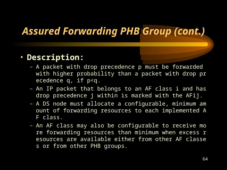
Assured Forwarding PHB Group (cont.)
• Description:– A packet with drop precedence p must be forwarded with hig
her probability than a packet with drop precedence q, if p<q.– An IP packet that belongs to an AF class i and has drop prec
edence j within is marked with the AFij.– A DS node must allocate a configurable, minimum amount of
forwarding resources to each implemented AF class.– An AF class may also be configurable to receive more forwa
rding resources than minimum when excess resources are available either from other AF classes or from other PHB groups.
65
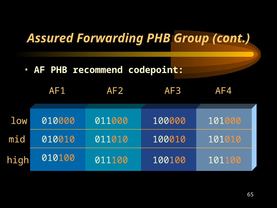
Assured Forwarding PHB Group (cont.)
• AF PHB recommend codepoint:
010000
010010
010100
011000 100000 101000
011010
011100 100100
100010
101100
101010
AF1 AF2 AF3 AF4
low
mid
high
66
Expedited Forwarding PHB
• Reference:– IETF RFC 2598.
• Description:– The EF PHB can be used to build a low loss, low latency,
low jitter, assured bandwidth, end-to-end service through DS domains.
– The departure rate of the aggregate’s packets from DS nodes must equal or exceed a configurable rate.
– The EF traffic receives this rate independent of the intensity of any other traffic attempting to transit the node.
67
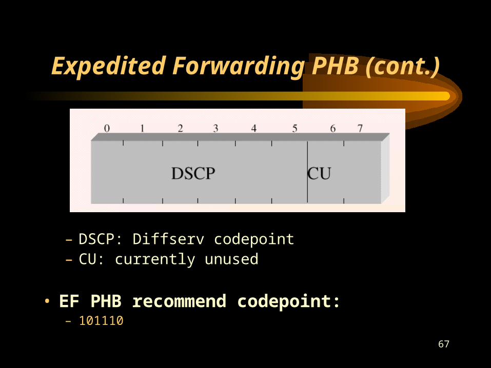
Expedited Forwarding PHB (cont.)
– DSCP: Diffserv codepoint– CU: currently unused
• EF PHB recommend codepoint:– 101110
68
Future Work
• Dynamic SLA.• Inter-domain and intra-domain signaling protocol.• The architectural framework of Interconnecting with n
on-DS domains (Combination of DiffServ and IntServ).
69
RSVP supported products
• Lucent– Cajun P550 Routing Switch Family.
• Nortel Networks– Versalar Switch Router 15000.
• Cisco– Cisco 7500 Family.– Cisco 7200 Family.– Catalyst 5000.– Cisco 6000 Family.– Cisco 8500 Family.
• Alcatel– PowerRail routing switches.
70
DiffServ supported products
• Lucent– PacketStar 6400 IP Switch.
• IBM– IBM 2210 Nways Multiprotocol Router.
• Alcatel– PowerRail routing switches.
• Cisco– Cisco 6000 Family.
71
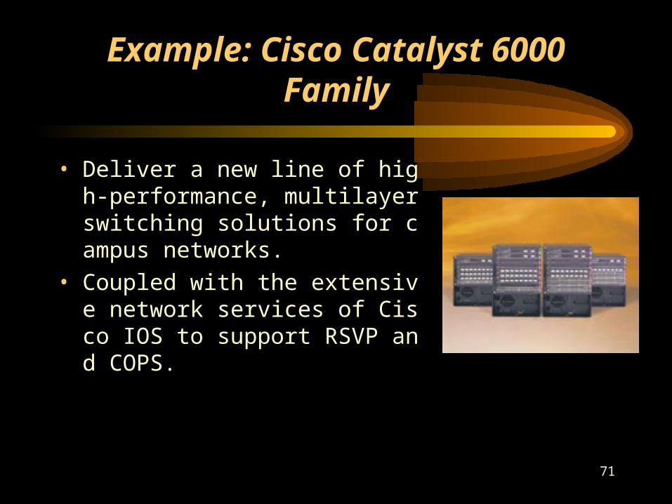
Example: Cisco Catalyst 6000 Family
• Deliver a new line of high-performance, multilayer switching solutions for campus networks.
• Coupled with the extensive network services of Cisco IOS to support RSVP and COPS.
72
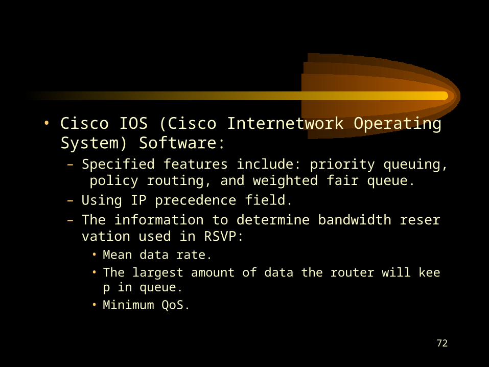
• Cisco IOS (Cisco Internetwork Operating System) Software:– Specified features include: priority queuing, policy routing, a
nd weighted fair queue.– Using IP precedence field.– The information to determine bandwidth reservation used in
RSVP:• Mean data rate.
• The largest amount of data the router will keep in queue.
• Minimum QoS.
73
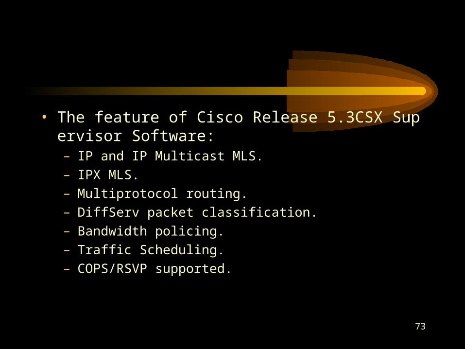
• The feature of Cisco Release 5.3CSX Supervisor Software:– IP and IP Multicast MLS.– IPX MLS.– Multiprotocol routing.– DiffServ packet classification.– Bandwidth policing.– Traffic Scheduling.– COPS/RSVP supported.


![QoS and Video Delivery Presented by Wei Wei. Internet QoS: A Big Picture [1][2][3][4] Current Internet approach Best effort No guarantees Need of providing](https://img.pdfslide.net/doc/110x75/56649d225503460f949f8cbb/qos-and-video-delivery-presented-by-wei-wei-internet-qos-a-big-picture-1234.jpg)