Embed Size (px)
Citation preview
INTERNATIONAL JOURNAL OF SCIENTIFIC & ENGINEERING RESEARCH, VOLUME 4, ISSUEɯƙ,ɯ, 8 2013
ISSN 2229-5518
IJSER © 2013
http://www.ijser.org
Study and Analysis of Composite Flat Plate
Prof.R.Arravind1, Dr.M.Saravanan2, R.Mohamed Rijuvan3
1Department of Aeronautical Engineering, Excel College of Engineering & Technology, Tamil Nadu, India2Principal, SBM College of Engineering & Technology, Tamil Nadu, India
3 Final Year , B.E Aeronautical Engineering, Excel College of Engineering & Technology, Tamil Nadu, IndiaEmail id: [email protected], [email protected], [email protected]
Abstract - In the framework of a composite technology, a composite fabrication technique are most widely used in the aerospace
and mechanical applications. Based on application of composite material, we can increase the strength of the materials and also
weight can be reduced. The composite flat plate made-up of three different layers was designed with help of CATIA v5R20 software
and analysis for maximum stress, strain, deformation for tensile and compressive testing condition. The layered flat was fabricated
with the G926/M18 and Kelvar-49 composite material. A static test demonstrated was carried out with the application of load, in
order to find out the load carrying capacity of the composite flat plate.
Keyword: Composite Flat Plate, Analysis, Delamination, Altair Hypermesh and MSC NASTRAN
—————————— ——————————
1. INTRODUCTION
The main goals of this Program were to
develop innovative design and manufacturing
technologies for composite components that can be
used on aerospace applications. Design of composite
materials requires consideration of a number of
constraints based on structural performance and
manufacturing considerations. Some of those
structural requirements are stiffness related such as
buckling performance, maximum displacements and
aerodynamic smoothness. Usually strength
requirements can be met by achieving the required
stiffness. From a manufacturing point of view; and
for unitized construction; the number of internal
mandrels required to produce the control surface can
usually yield a relative cost comparison between
different structural lay-outs. Standard design
methodology operates on the assumption of an
internal configuration at the conceptual design stage
followed by analysis. This result be very useful for
designing and fabrication of aerospace structures
and also automobile industries. In aerospace
industries, weight reduction and increase of strength
plays a Vitol role. In automobile industries, the race
cars structures are now a day’s made up of
composite materials. So this material will be more
Suitable for them. The Analysis procedure and
results are discussed below.
2. METHODOLOGY
3. MATERIAL PROPERTIES
• Material : Kevlar 49
• Density : 0.052 lb/in3
Geometry, Loads, Specifications, Interface
Design Optimization
Topological
Parametric
Optimized Concept
Detailed Design
276
IJSER
INTERNATIONAL JOURNAL OF SCIENTIFIC & ENGINEERING RESEARCH, VOLUME 4, ISSUEɯƙȮɯ, 8 2013
ISSN 2229-5518
IJSER © 2013
http://www.ijser.org
• Young’s Modulus : 16.3 × 10⁶ psi
• Poisson’s ratio : 0.36
-----------------------------------------------------------------
• Material : G926/M18
• Young’s Modulus : 7E+4 MPa
• Poisson’s ratio : 0.04
Fig.1.1 Composite Plate with Three layers
4. PROCEDURE1. Define Geometry: First of all, we have to define
the geometry and dimension for the composite
flat plate. With the help of obtained geometry,
we have to design 3D model of the plate with the
help of CAD Package softwares like Pro/E, Catia
and NX CAD. After model has been designed,
we have to save the modeled design in the
common format like IGES or STEP.
Fig.1.2 Geometry
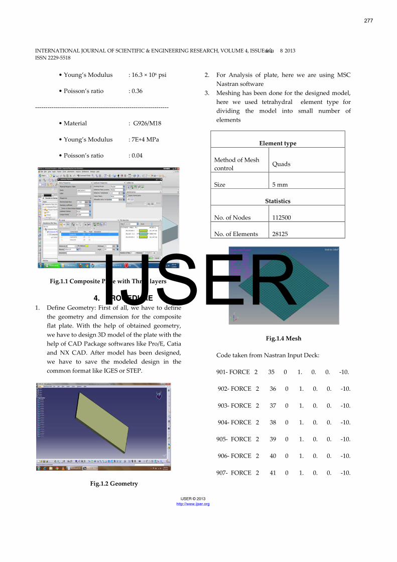
2. For Analysis of plate, here we are using MSC
Nastran software
3. Meshing has been done for the designed model,
here we used tetrahydral element type for
dividing the model into small number of
elements
Element type
Method of Mesh
controlQuads
Size 5 mm
Statistics
No. of Nodes 112500
No. of Elements 28125
Fig.1.4 Mesh
Code taken from Nastran Input Deck:
901- FORCE 2 35 0 1. 0. 0. -10.
902- FORCE 2 36 0 1. 0. 0. -10.
903- FORCE 2 37 0 1. 0. 0. -10.
904- FORCE 2 38 0 1. 0. 0. -10.
905- FORCE 2 39 0 1. 0. 0. -10.
906- FORCE 2 40 0 1. 0. 0. -10.
907- FORCE 2 41 0 1. 0. 0. -10.
277
IJSER
INTERNATIONAL JOURNAL OF SCIENTIFIC & ENGINEERING RESEARCH, VOLUME 4, ISSUEɯƙɯȮɯ, 8 2013
ISSN 2229-5518
IJSER © 2013
http://www.ijser.org
908- FORCE 2 42 0 1. 0. 0. -10.
909- FORCE 2 43 0 1. 0. 0. -10.
910- FORCE 2 44 0 1. 0. 0. -10.
911- FORCE 2 45 0 1. 0. 0. -10.
912- FORCE 2 46 0 1. 0. 0. -10.
913- FORCE 2 47 0 1. 0. 0. -10.
914- FORCE 2 48 0 1. 0. 0. -10.
915- FORCE 2 49 0 1. 0. 0. -10.
916- FORCE 2 50 0 1. 0. 0. -10.
917- FORCE 2 51 0 1. 0. 0. -10.
918- FORCE 2 52 0 1. 0. 0. -10.
919- FORCE 2 53 0 1. 0. 0. -10.
920- FORCE 2 54 0 1. 0. 0. -10.
921- FORCE 2 55 0 1. 0. 0. -10.
922- FORCE 2 56 0 1. 0. 0. -10.
923- FORCE 2 57 0 1. 0. 0. -10.
924- FORCE 2 58 0 1. 0. 0. -10.
925- FORCE 2 59 0 1. 0. 0. -10.
926- FORCE 2 60 0 1. 0. 0. -10.
927- FORCE 2 61 0 1. 0. 0. -10.
928- FORCE 2 62 0 1. 0. 0. -10.
929- FORCE 2 63 0 1. 0. 0. -10.
930- FORCE 2 64 0 1. 0. 0. -10.
931- FORCE 2 65 0 1. 0. 0. -10.
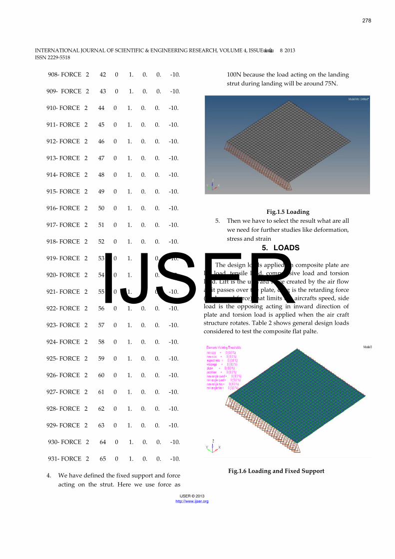
4. We have defined the fixed support and force
acting on the strut. Here we use force as
100N because the load acting on the landing
strut during landing will be around 75N.
Fig.1.5 Loading
5. Then we have to select the result what are all
we need for further studies like deformation,
stress and strain
5. LOADS
The design loads applied on composite plate are
lift load, tensile load, compressive load and torsion
load. Lift is the upward force created by the air flow
as it passes over the plate, drag is the retarding force
(back ward force) that limits the aircrafts speed, side
load is the opposing acting in inward direction of
plate and torsion load is applied when the air craft
structure rotates. Table 2 shows general design loads
considered to test the composite flat palte.
Fig.1.6 Loading and Fixed Support
278
IJSER
INTERNATIONAL JOURNAL OF SCIENTIFIC & ENGINEERING RESEARCH, VOLUME 4, ISSUEɯƙȮɯ, 8 2013
ISSN 2229-5518
IJSER © 2013
http://www.ijser.org
1: Composite Flat Plate (Design Loads)
Type of Load Value
Load 10 N
With the above all specifications the model
was designed in CATIA (Ver-5), meshed in
HYPERMESH (Ver-12) and the results are viewed in
MSC NASTRAN (Ver-12).
6. STRUCTURAL ANALYSIS
There are several types of structural analysis
which play an important role in finding the
structural safety under stress and deformation. From
that the basic structural safety of the component can
be found by analyzing the structure for static and
dynamic loading conditions.
7. STATIC ANALYSIS:
A static analysis is used to calculate the
effects of steady loading conditions on a structure,
while ignoring inertia and damping effects, such as
those caused by time-varying loads. This analysis has
been done by applying static loads and results are
presented for the displacements and vonmises
stresses, because vonmises stress theory is the main
failure theory to find the failure of the components or
factor of safety in the problem.
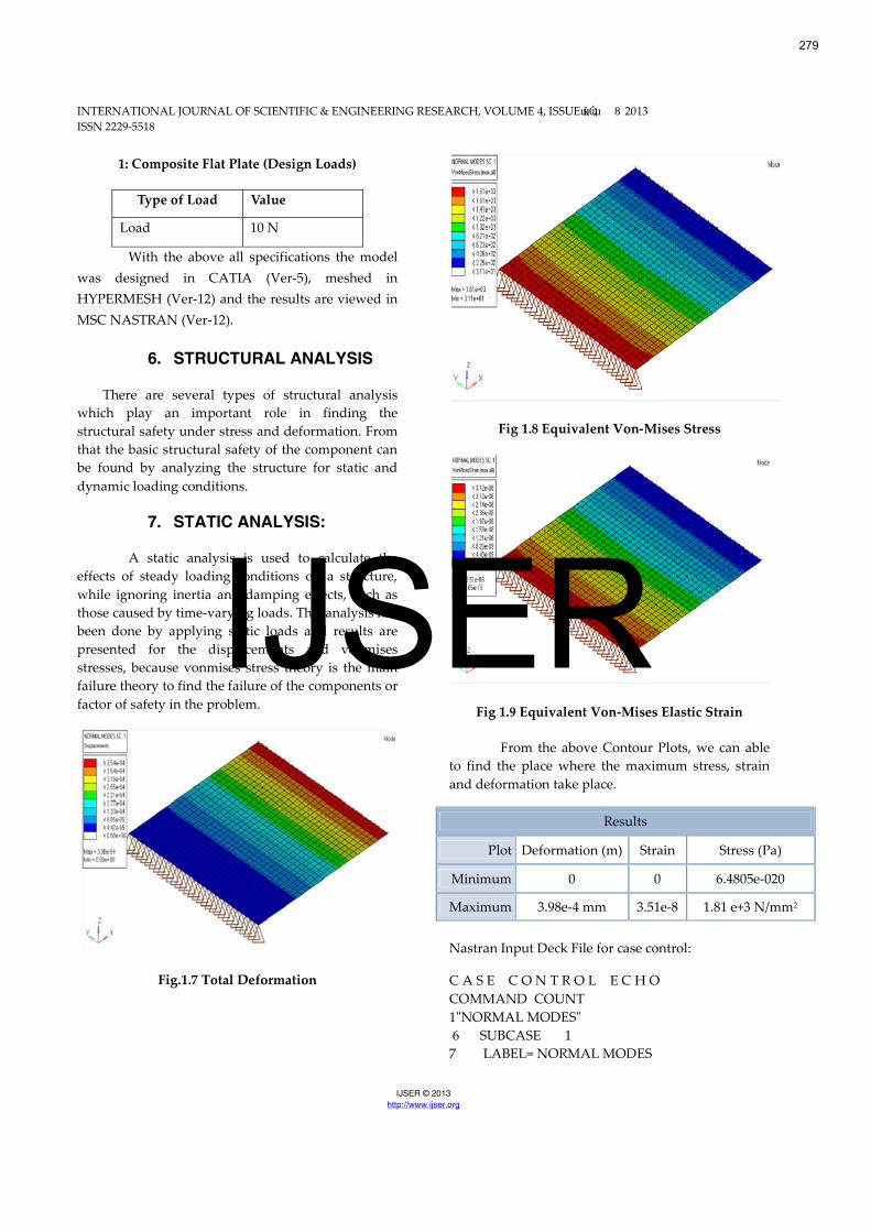
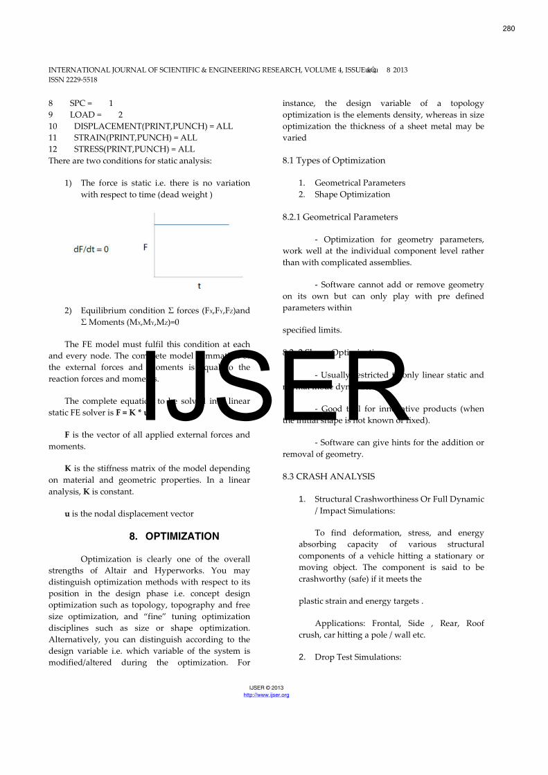
Fig.1.7 Total Deformation
Fig 1.8 Equivalent Von-Mises Stress
Fig 1.9 Equivalent Von-Mises Elastic Strain
From the above Contour Plots, we can able
to find the place where the maximum stress, strain
and deformation take place.
Results
Plot Deformation (m) Strain Stress (Pa)
Minimum 0 0 6.4805e-020
Maximum 3.98e-4 mm 3.51e-8 1.81 e+3 N/mm2
Nastran Input Deck File for case control:
C A S E C O N T R O L E C H O
COMMAND COUNT
1"NORMAL MODES"
6 SUBCASE 1
7 LABEL= NORMAL MODES
279
IJSER
INTERNATIONAL JOURNAL OF SCIENTIFIC & ENGINEERING RESEARCH, VOLUME 4, ISSUEɯƙȮɯ, 8 2013
ISSN 2229-5518
IJSER © 2013
http://www.ijser.org
8 SPC = 1
9 LOAD = 2
10 DISPLACEMENT(PRINT,PUNCH) = ALL
11 STRAIN(PRINT,PUNCH) = ALL
12 STRESS(PRINT,PUNCH) = ALL
There are two conditions for static analysis:
1) The force is static i.e. there is no variation
with respect to time (dead weight )
2) Equilibrium condition Σ forces (FX,FY,FZ)and
Σ Moments (MX,MY,MZ)=0
The FE model must fulfil this condition at each
and every node. The complete model summation of
the external forces and moments is equal to the
reaction forces and moments.
The complete equation to be solved in a linear
static FE solver is F = K * u.
F is the vector of all applied external forces and
moments.
K is the stiffness matrix of the model depending
on material and geometric properties. In a linear
analysis, K is constant.
u is the nodal displacement vector
8. OPTIMIZATION
Optimization is clearly one of the overall
strengths of Altair and Hyperworks. You may
distinguish optimization methods with respect to its
position in the design phase i.e. concept design
optimization such as topology, topography and free
size optimization, and “fine” tuning optimization
disciplines such as size or shape optimization.
Alternatively, you can distinguish according to the
design variable i.e. which variable of the system is
modified/altered during the optimization. For
instance, the design variable of a topology
optimization is the elements density, whereas in size
optimization the thickness of a sheet metal may be
varied
8.1 Types of Optimization
1. Geometrical Parameters
2. Shape Optimization
8.2.1 Geometrical Parameters
- Optimization for geometry parameters,
work well at the individual component level rather
than with complicated assemblies.
- Software cannot add or remove geometry
on its own but can only play with pre defined
parameters within
specified limits.
8.2..2 Shape Optimization
- Usually restricted to only linear static and
normal mode dynamics.
- Good tool for innovative products (when
the initial shape is not known or fixed).
- Software can give hints for the addition or
removal of geometry.
8.3 CRASH ANALYSIS
1. Structural Crashworthiness Or Full Dynamic
/ Impact Simulations:
To find deformation, stress, and energy
absorbing capacity of various structural
components of a vehicle hitting a stationary or
moving object. The component is said to be
crashworthy (safe) if it meets the
plastic strain and energy targets .
Applications: Frontal, Side , Rear, Roof
crush, car hitting a pole / wall etc.
2. Drop Test Simulations:
280
IJSER
INTERNATIONAL JOURNAL OF SCIENTIFIC & ENGINEERING RESEARCH, VOLUME 4, ISSUEɯƙȮɯ, 8 2013
ISSN 2229-5518
IJSER © 2013
http://www.ijser.org
Drop test is a free fall test carried out to
check the structural integrity of the component .
Applications : Black box of an aircraft,
mobile phone, consumer goods such as TV,
fridge etc
3. Occupant Safety
To find the effects of crash on the human
body and making the ride safe for the driver as
well as the passengers. Several regulations exist
in different countries to ensure a proper
certification.
e.g.: FMVSS (Federal Motor Vehicle Safety
Standards) in the USA, ECE (Economic
Commission of Europe) regulation in Europe. In
Indiea, the ARAI has set up standard procedures
for the Automobile industry and called AIS (
Automotive Industry Standards )
Advantages of FEA
Visualization
Design cycle time
No. of prototypes
Testing
Optimum design
9. CONCLUSIONS
In the framework of a composite technology,
composite flat plate was designed and tested using
MSC NASTRAN 2012. It is proved that composite
flat plate failed beyond their Design Ultimate Load
Level and also determine the maximum loading
conditions for plate made up of composite G926/M18
and Kelvar-49 material. Therefore, the load carrying
capability and impact loading of the composite plate
was demonstrated successfully.
FUTURE SCOPE
Present dissertation work covers the design
and analysis, but still it has a scope for shape
optimization. All components are required corrosion
protection. Corrosion control is needed for all ferrous
and non ferrous materials of aircraft structures by
considering:
• Coatings and/or cathodic protection
• Use of a corrosion allowance
• Inspection/monitoring of corrosion
• Control of humidity for internal zones
(Compartments)
REFERENCES
[1] Silvio Merazzi, “Modular Finite Element Analysis ToolsApplied to Problems in engineering, Ph.d These no. 1251,Ecole Polythenique Federale de Lausanne, EPFL 1994.
[2] P. Arendsen, “The B2000 Optimisation Module: B2OPT”,NLR Technical Publication 94116L, GARTEUR AG13Structural Optimisation, March 1993.
[3] P.H.J. Vosbeek, “Analysis of Upper and Lower Compositetorque link, MTR9803, May 1998.
[4] H.G.S.J. Thuis, “Composite torque link test specificationreport CODEMA composite landing gear”, NLR-CR-98083,February 1998.
281
IJSER