Embed Size (px)
Citation preview
1: Introduction 1
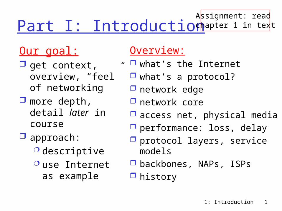
Part I: Introduction
Our goal: get context,
overview, “feel” of networking
more depth, detail later in course
approach: descriptive use Internet as
example
Overview: what’s the Internet what’s a protocol? network edge network core access net, physical media performance: loss, delay protocol layers, service
models backbones, NAPs, ISPs history
Assignment: read chapter 1 in text
1: Introduction 2
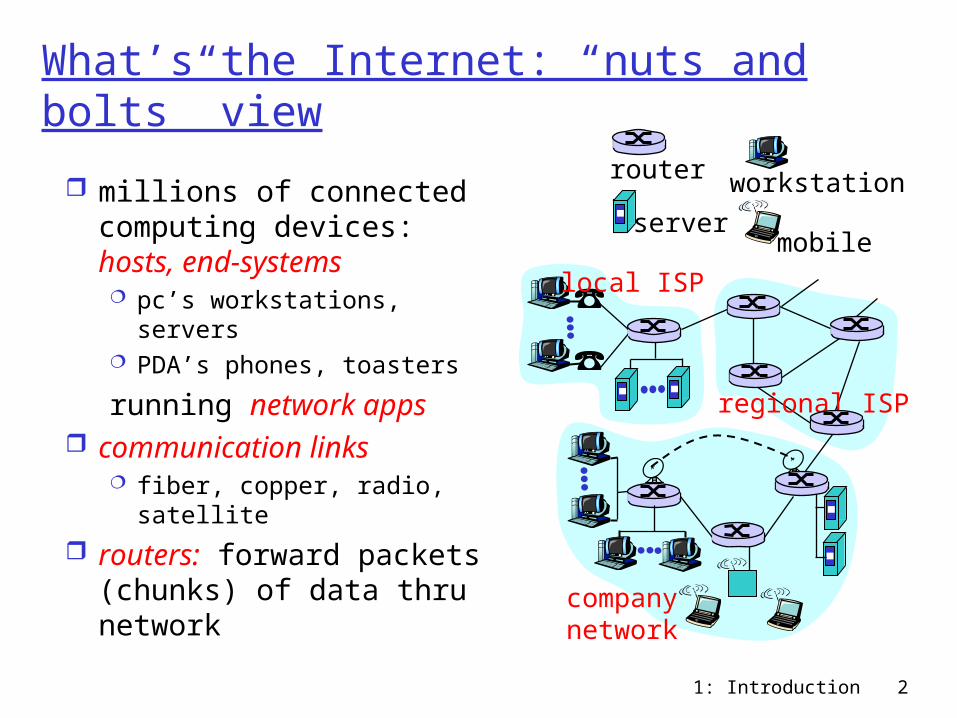
What’s the Internet: “nuts and bolts” view
millions of connected computing devices: hosts, end-systems pc’s workstations, servers PDA’s phones, toasters
running network apps communication links
fiber, copper, radio, satellite
routers: forward packets (chunks) of data thru network
local ISP
companynetwork
regional ISP
router workstation
servermobile
1: Introduction 3
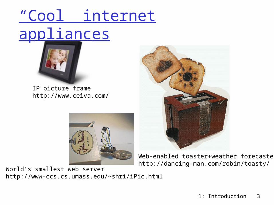
“Cool” internet appliances
World’s smallest web serverhttp://www-ccs.cs.umass.edu/~shri/iPic.html
IP picture framehttp://www.ceiva.com/
Web-enabled toaster+weather forecasterhttp://dancing-man.com/robin/toasty/

1: Introduction 4
What’s the Internet: “nuts and bolts” view protocols: control sending,
receiving of msgs e.g., TCP, IP, HTTP, FTP, PPP
Internet: “network of networks” loosely hierarchical public Internet versus private
intranet
Internet standards RFC: Request for comments IETF: Internet Engineering
Task Force
local ISP
companynetwork
regional ISP
router workstation
servermobile
1: Introduction 5
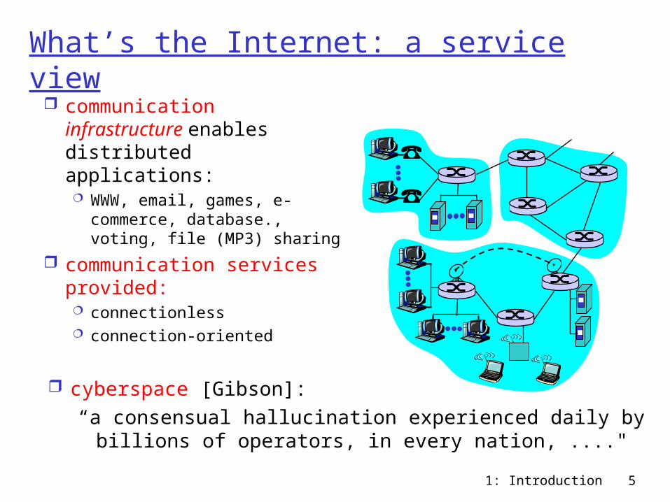
What’s the Internet: a service view communication
infrastructure enables distributed applications: WWW, email, games, e-
commerce, database., voting, file (MP3) sharing
communication services provided: connectionless connection-oriented
cyberspace [Gibson]:“a consensual hallucination experienced daily by
billions of operators, in every nation, ...."
1: Introduction 6
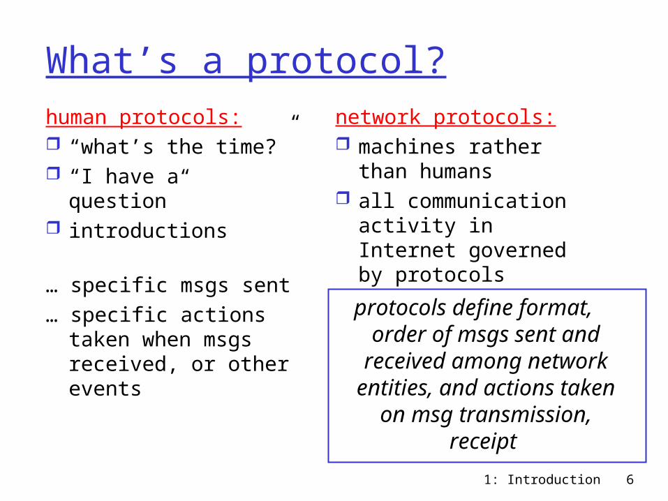
What’s a protocol?human protocols: “what’s the time?” “I have a question” introductions
… specific msgs sent… specific actions
taken when msgs received, or other events
network protocols: machines rather than
humans all communication
activity in Internet governed by protocols
protocols define format, order of msgs sent and
received among network entities, and actions taken on msg transmission, receipt
1: Introduction 7
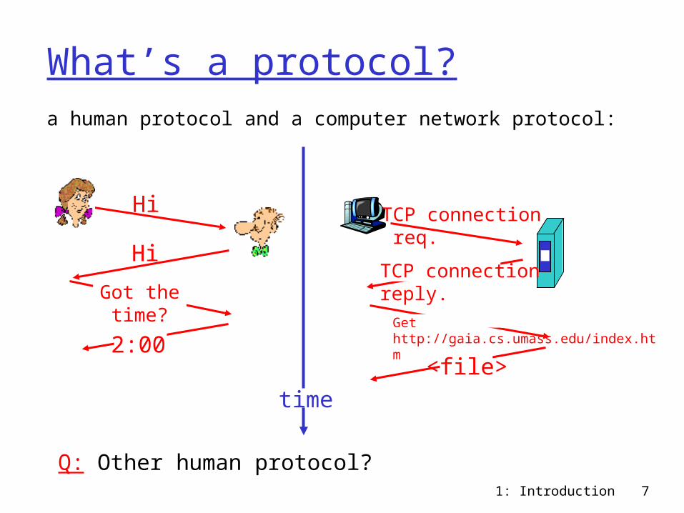
What’s a protocol?a human protocol and a computer network protocol:
Q: Other human protocol?
Hi
Hi
Got thetime?
2:00
TCP connection req.
TCP connectionreply.Get http://gaia.cs.umass.edu/index.htm
<file>time
1: Introduction 8
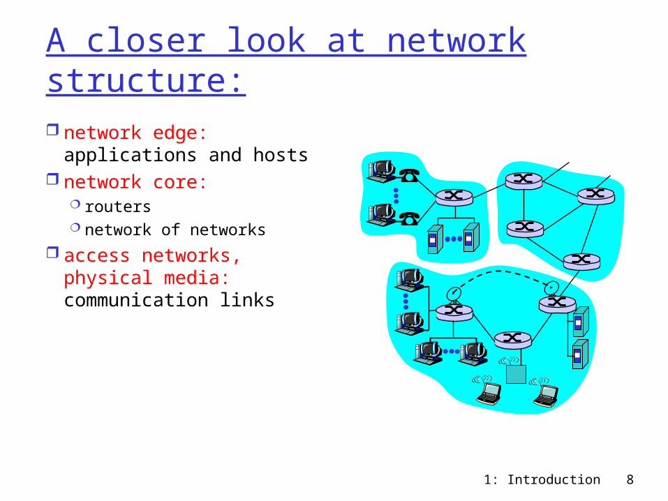
A closer look at network structure: network edge:
applications and hosts network core:
routers network of networks
access networks, physical media: communication links
1: Introduction 9
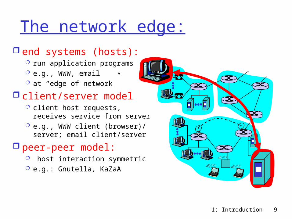
The network edge: end systems (hosts):
run application programs e.g., WWW, email at “edge of network”
client/server model client host requests,
receives service from server e.g., WWW client (browser)/
server; email client/server
peer-peer model: host interaction symmetric e.g.: Gnutella, KaZaA
1: Introduction 10
Network edge: connection-oriented service
Goal: data transfer between end sys.
handshaking: setup (prepare for) data transfer ahead of time Hello, hello back
human protocol set up “state” in two
communicating hosts
TCP - Transmission Control Protocol Internet’s connection-
oriented service
TCP service [RFC 793] reliable, in-order byte-
stream data transfer loss: acknowledgements
and retransmissions
flow control: sender won’t overwhelm
receiver
congestion control: senders “slow down
sending rate” when network congested
1: Introduction 11
Network edge: connectionless service
Goal: data transfer between end systems same as before!
UDP - User Datagram Protocol [RFC 768]: Internet’s connectionless service unreliable data
transfer no flow control no congestion
control
App’s using TCP: HTTP (WWW), FTP
(file transfer), Telnet (remote login), SMTP (email)
App’s using UDP: streaming media,
teleconferencing, Internet telephony
1: Introduction 12
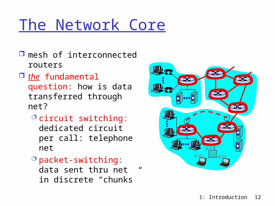
The Network Core
mesh of interconnected routers
the fundamental question: how is data transferred through net? circuit switching:
dedicated circuit per call: telephone net
packet-switching: data sent thru net in discrete “chunks”
1: Introduction 13
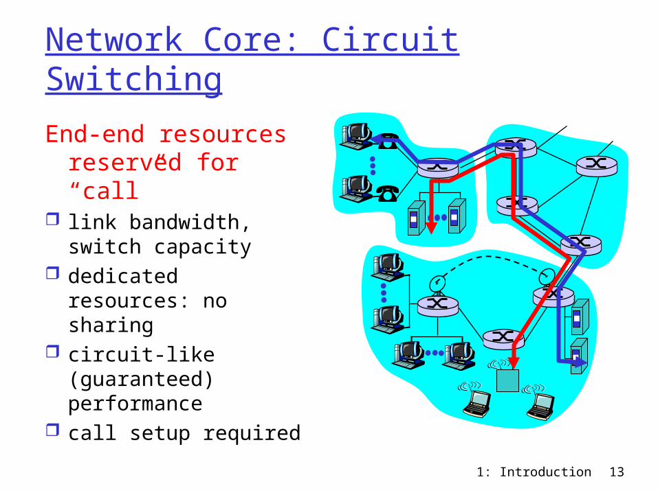
Network Core: Circuit Switching
End-end resources reserved for “call”
link bandwidth, switch capacity
dedicated resources: no sharing
circuit-like (guaranteed) performance
call setup required
1: Introduction 14
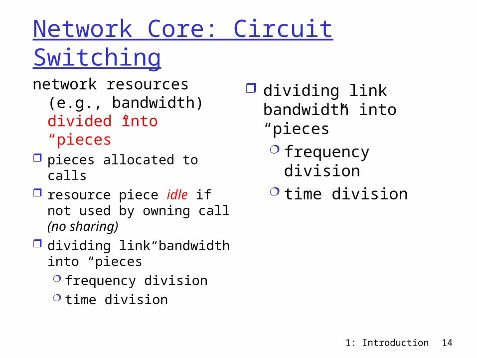
Network Core: Circuit Switching
network resources (e.g., bandwidth) divided into “pieces”
pieces allocated to calls resource piece idle if
not used by owning call (no sharing)
dividing link bandwidth into “pieces” frequency division time division
dividing link bandwidth into “pieces” frequency division time division
1: Introduction 15
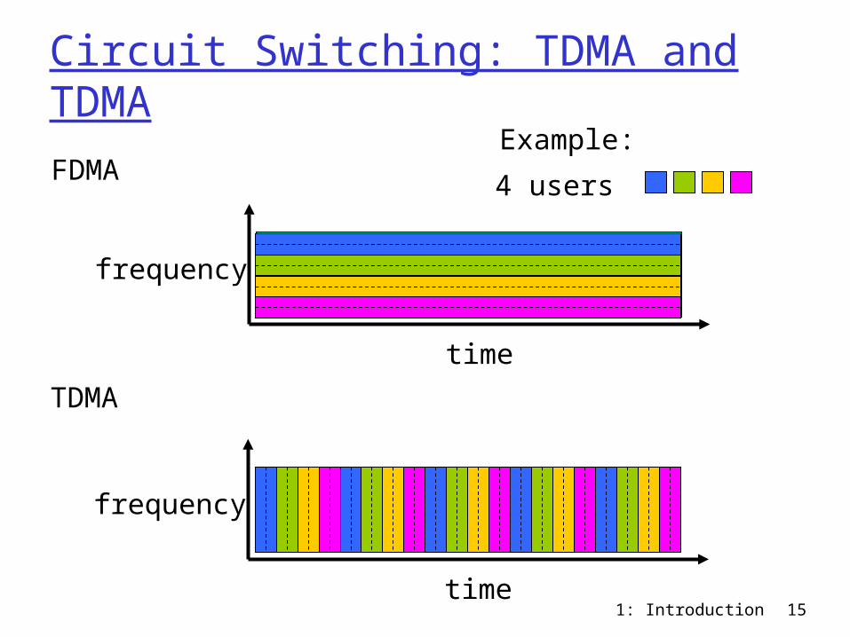
Circuit Switching: TDMA and TDMA
FDMA
frequency
time
TDMA
frequency
time
4 users
Example:
1: Introduction 16
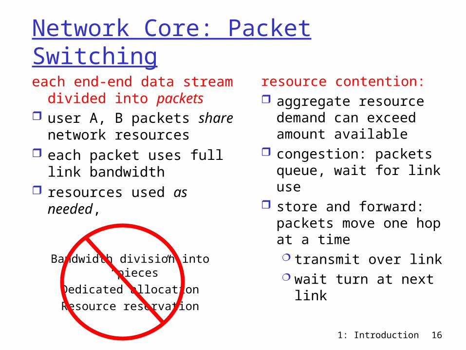
Network Core: Packet Switching
each end-end data stream divided into packets
user A, B packets share network resources
each packet uses full link bandwidth
resources used as needed,
resource contention: aggregate resource
demand can exceed amount available
congestion: packets queue, wait for link use
store and forward: packets move one hop at a time transmit over link wait turn at next
link
Bandwidth division into “pieces”Dedicated allocationResource reservation
1: Introduction 17
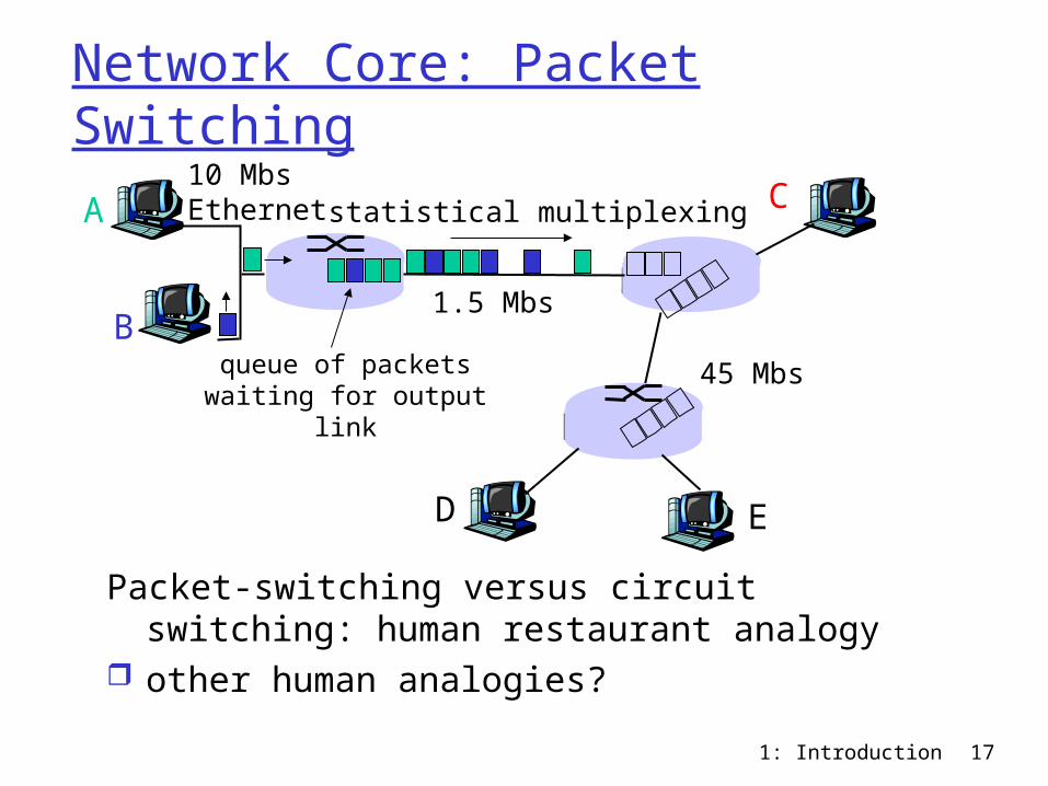
Network Core: Packet Switching
Packet-switching versus circuit switching: human restaurant analogy
other human analogies?
A
B
C10 MbsEthernet
1.5 Mbs
45 Mbs
D E
statistical multiplexing
queue of packetswaiting for output
link
1: Introduction 18
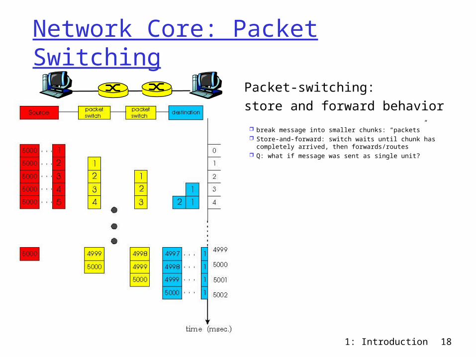
Network Core: Packet Switching
Packet-switching: store and forward behavior
break message into smaller chunks: “packets” Store-and-forward: switch waits until chunk has
completely arrived, then forwards/routes Q: what if message was sent as single unit?
1: Introduction 19
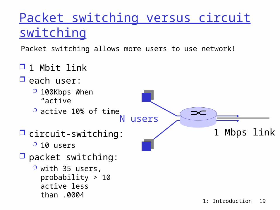
Packet switching versus circuit switching
1 Mbit link each user:
100Kbps when “active”
active 10% of time
circuit-switching: 10 users
packet switching: with 35 users,
probability > 10 active less than .0004
Packet switching allows more users to use network!
N users
1 Mbps link
1: Introduction 20
Packet switching versus circuit switching
Great for bursty data resource sharing no call setup
Excessive congestion: packet delay and loss protocols needed for reliable data transfer,
congestion control Q: How to provide circuit-like behavior?
bandwidth guarantees needed for audio/video apps
still an unsolved problem (chapter 6)
Is packet switching a “slam dunk winner?”
1: Introduction 21
Packet-switched networks: routing
Goal: move packets among routers from source to destination we’ll study several path selection algorithms (chapter 4)
datagram network: destination address determines next hop routes may change during session analogy: driving, asking directions
virtual circuit network: each packet carries tag (virtual circuit ID), tag determines
next hop fixed path determined at call setup time, remains fixed
thru call routers maintain per-call state
1: Introduction 22
Access networks and physical media
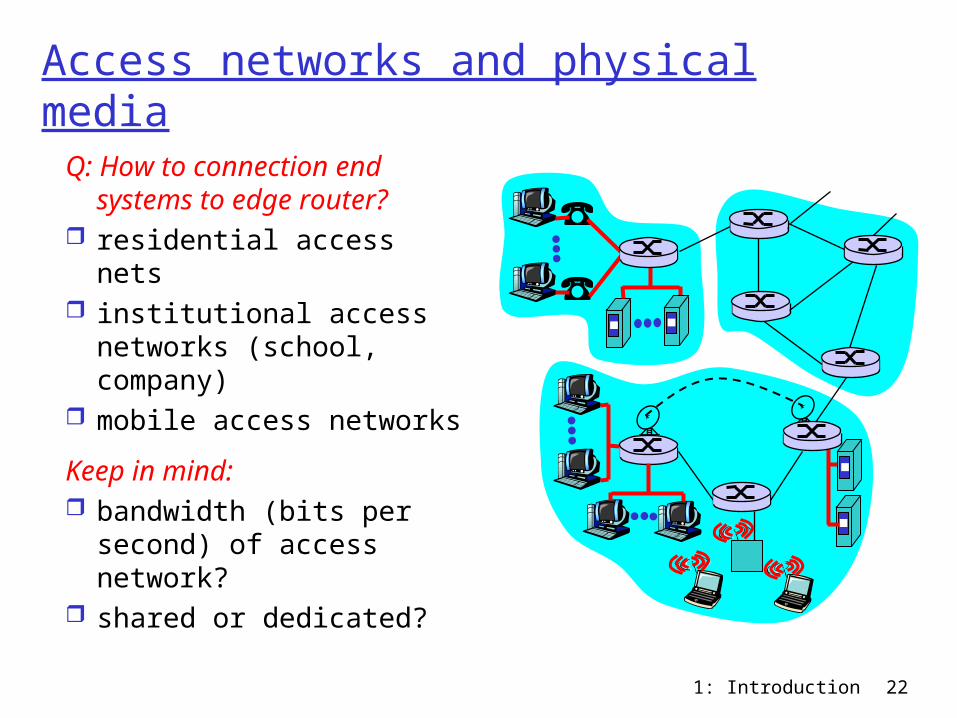
Q: How to connection end systems to edge router?
residential access nets institutional access
networks (school, company)
mobile access networks
Keep in mind: bandwidth (bits per
second) of access network?
shared or dedicated?
1: Introduction 23
Residential access: point to point access
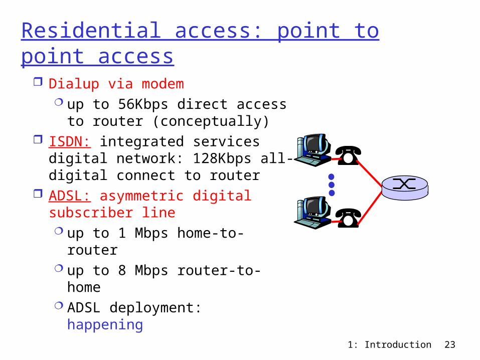
Dialup via modem up to 56Kbps direct access
to router (conceptually) ISDN: integrated services
digital network: 128Kbps all-digital connect to router
ADSL: asymmetric digital subscriber line up to 1 Mbps home-to-router up to 8 Mbps router-to-home ADSL deployment:
happening
1: Introduction 24
Residential access: cable modems
HFC: hybrid fiber coax asymmetric: up to 10Mbps upstream, 1
Mbps downstream network of cable and fiber attaches homes
to ISP router shared access to router among home issues: congestion, dimensioning
deployment: available via cable companies, e.g., MediaOne
1: Introduction 25
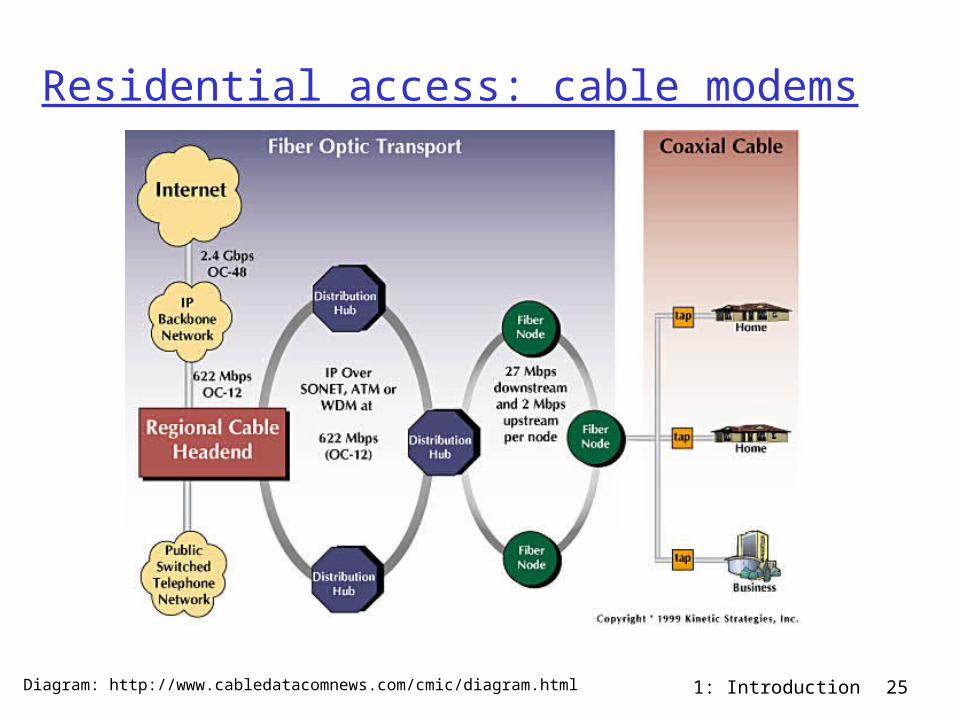
Residential access: cable modems
Diagram: http://www.cabledatacomnews.com/cmic/diagram.html
1: Introduction 26
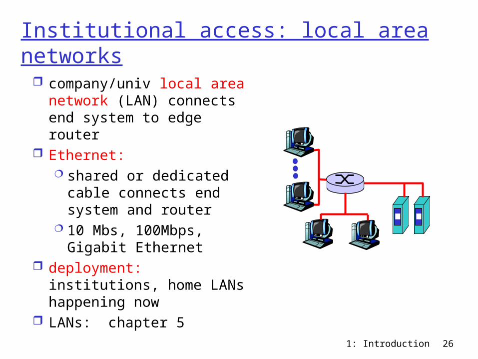
Institutional access: local area networks
company/univ local area network (LAN) connects end system to edge router
Ethernet: shared or dedicated
cable connects end system and router
10 Mbs, 100Mbps, Gigabit Ethernet
deployment: institutions, home LANs happening now
LANs: chapter 5
1: Introduction 27
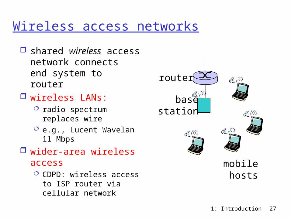
Wireless access networks
shared wireless access network connects end system to router
wireless LANs: radio spectrum replaces
wire e.g., Lucent Wavelan 11
Mbps
wider-area wireless access CDPD: wireless access
to ISP router via cellular network
basestation
mobilehosts
router
1: Introduction 28
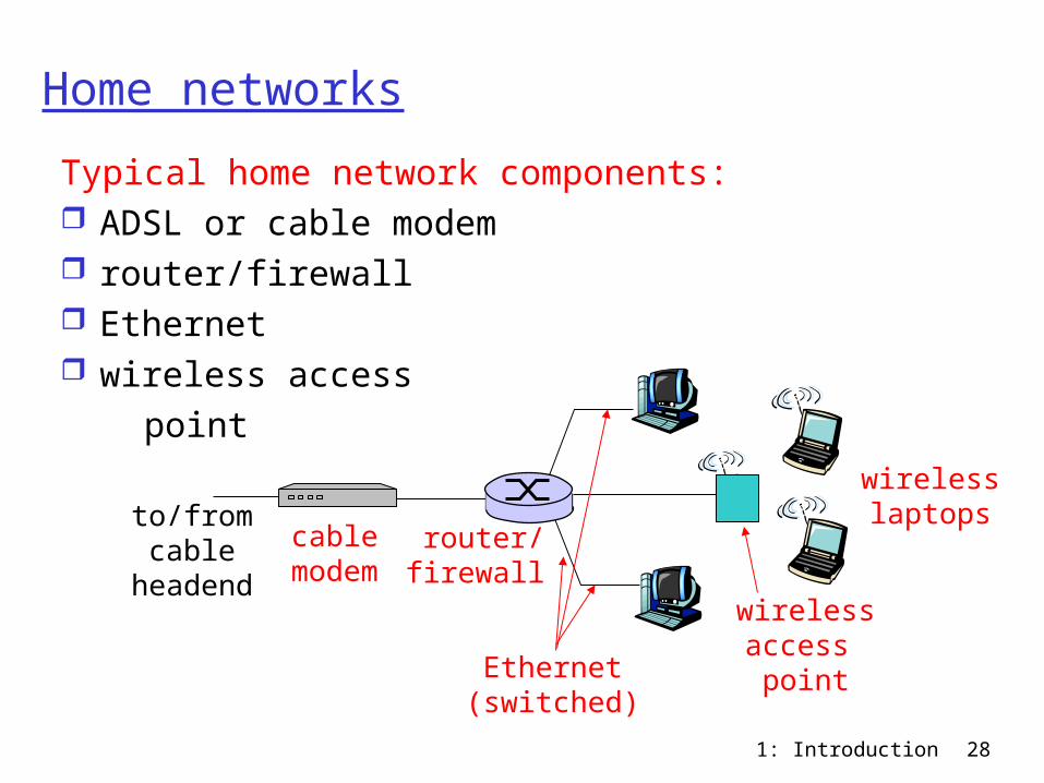
Home networks
Typical home network components: ADSL or cable modem router/firewall Ethernet wireless access point
wirelessaccess point
wirelesslaptops
router/firewall
cablemodem
to/fromcable
headend
Ethernet(switched)
1: Introduction 29
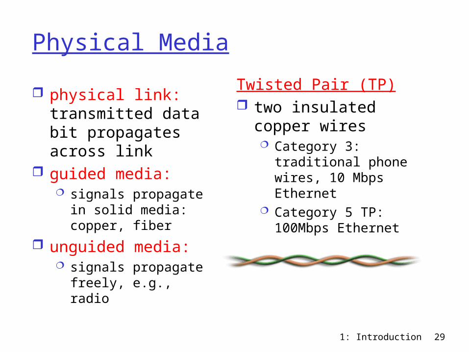
Physical Media
physical link: transmitted data bit propagates across link
guided media: signals propagate in
solid media: copper, fiber
unguided media: signals propagate
freely, e.g., radio
Twisted Pair (TP) two insulated copper
wires Category 3: traditional
phone wires, 10 Mbps Ethernet
Category 5 TP: 100Mbps Ethernet
1: Introduction 30
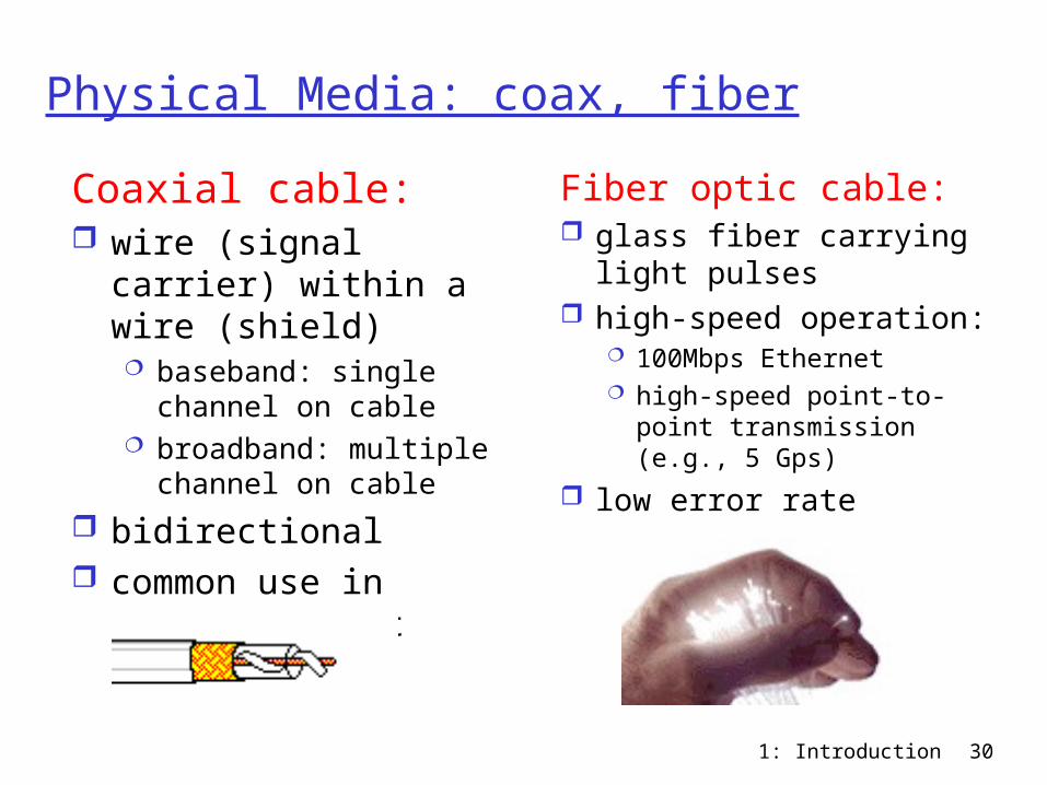
Physical Media: coax, fiber
Coaxial cable: wire (signal carrier)
within a wire (shield) baseband: single
channel on cable broadband: multiple
channel on cable
bidirectional common use in
10Mbs Ethernet
Fiber optic cable: glass fiber carrying
light pulses high-speed operation:
100Mbps Ethernet high-speed point-to-
point transmission (e.g., 5 Gps)
low error rate
1: Introduction 31
Physical media: radio
signal carried in electromagnetic spectrum
no physical “wire” bidirectional propagation
environment effects: reflection obstruction by objects interference
Radio link types: microwave
e.g. up to 45 Mbps channels
LAN (e.g., WaveLAN) 2Mbps, 11Mbps
wide-area (e.g., cellular) e.g. CDPD, 10’s Kbps
satellite up to 50Mbps channel (or multiple
smaller channels) 270 Msec end-end delay geosynchronous versus LEOS
1: Introduction 32
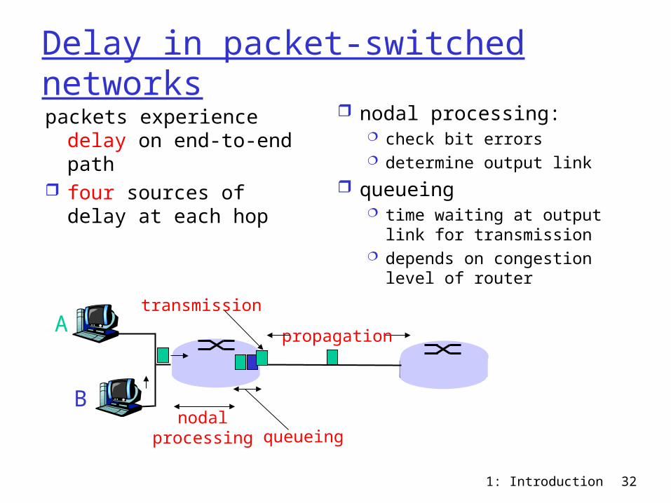
Delay in packet-switched networkspackets experience delay
on end-to-end path four sources of delay at
each hop
nodal processing: check bit errors determine output link
queueing time waiting at output
link for transmission depends on congestion
level of router
A
B
propagation
transmission
nodalprocessing queueing
1: Introduction 33
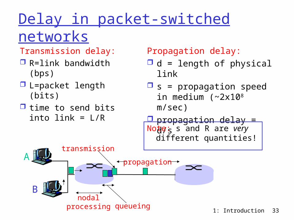
Delay in packet-switched networksTransmission delay: R=link bandwidth
(bps) L=packet length (bits) time to send bits into
link = L/R
Propagation delay: d = length of physical
link s = propagation speed in
medium (~2x10⁸ m/sec) propagation delay = d/s
A
B
propagation
transmission
nodalprocessing queueing
Note: s and R are very different quantities!
1: Introduction 34
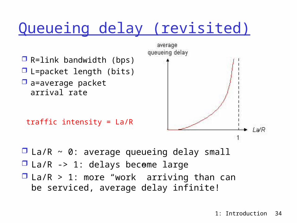
Queueing delay (revisited)
R=link bandwidth (bps) L=packet length (bits) a=average packet
arrival rate
traffic intensity = La/R
La/R ~ 0: average queueing delay small La/R -> 1: delays become large La/R > 1: more “work” arriving than can
be serviced, average delay infinite!
1: Introduction 35
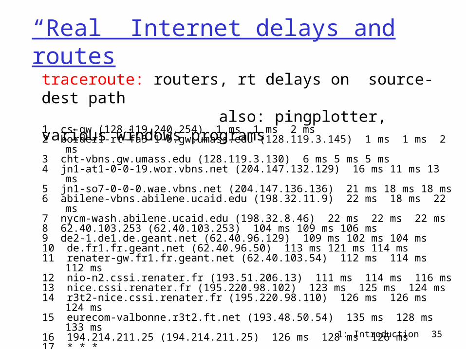
“Real” Internet delays and routes
1 cs-gw (128.119.240.254) 1 ms 1 ms 2 ms2 border1-rt-fa5-1-0.gw.umass.edu (128.119.3.145) 1 ms 1 ms 2 ms3 cht-vbns.gw.umass.edu (128.119.3.130) 6 ms 5 ms 5 ms4 jn1-at1-0-0-19.wor.vbns.net (204.147.132.129) 16 ms 11 ms 13 ms 5 jn1-so7-0-0-0.wae.vbns.net (204.147.136.136) 21 ms 18 ms 18 ms 6 abilene-vbns.abilene.ucaid.edu (198.32.11.9) 22 ms 18 ms 22 ms7 nycm-wash.abilene.ucaid.edu (198.32.8.46) 22 ms 22 ms 22 ms8 62.40.103.253 (62.40.103.253) 104 ms 109 ms 106 ms9 de2-1.de1.de.geant.net (62.40.96.129) 109 ms 102 ms 104 ms10 de.fr1.fr.geant.net (62.40.96.50) 113 ms 121 ms 114 ms11 renater-gw.fr1.fr.geant.net (62.40.103.54) 112 ms 114 ms 112 ms12 nio-n2.cssi.renater.fr (193.51.206.13) 111 ms 114 ms 116 ms13 nice.cssi.renater.fr (195.220.98.102) 123 ms 125 ms 124 ms14 r3t2-nice.cssi.renater.fr (195.220.98.110) 126 ms 126 ms 124 ms15 eurecom-valbonne.r3t2.ft.net (193.48.50.54) 135 ms 128 ms 133 ms16 194.214.211.25 (194.214.211.25) 126 ms 128 ms 126 ms17 * * *18 * * *19 fantasia.eurecom.fr (193.55.113.142) 132 ms 128 ms 136 ms
traceroute: routers, rt delays on source-dest path also: pingplotter, various windows programs
1: Introduction 36
Protocol “Layers”Networks are
complex! many “pieces”:
hosts routers links of various
media applications protocols hardware,
software
Question: Is there any hope of organizing structure of
network?
Or at least our discussion of networks?
1: Introduction 37
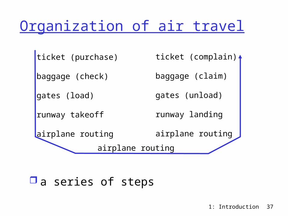
Organization of air travel
a series of steps
ticket (purchase)
baggage (check)
gates (load)
runway takeoff
airplane routing
ticket (complain)
baggage (claim)
gates (unload)
runway landing
airplane routing
airplane routing
1: Introduction 38
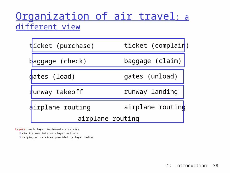
Organization of air travel: a different view
Layers: each layer implements a service via its own internal-layer actions relying on services provided by layer below
ticket (purchase)
baggage (check)
gates (load)
runway takeoff
airplane routing
ticket (complain)
baggage (claim)
gates (unload)
runway landing
airplane routing
airplane routing
1: Introduction 39
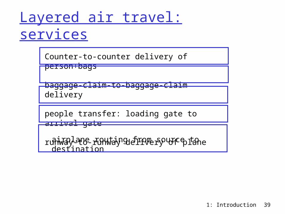
Layered air travel: services
Counter-to-counter delivery of person+bags
baggage-claim-to-baggage-claim delivery
people transfer: loading gate to arrival gate
runway-to-runway delivery of plane
airplane routing from source to destination
1: Introduction 40
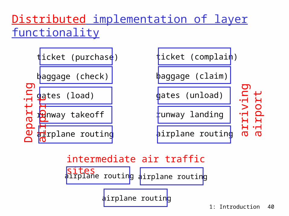
Distributed implementation of layer functionality
ticket (purchase)
baggage (check)
gates (load)
runway takeoff
airplane routing
ticket (complain)
baggage (claim)
gates (unload)
runway landing
airplane routing
airplane routing
Dep
art
ing
air
port
arr
ivin
g
air
port
intermediate air traffic sites
airplane routing airplane routing
1: Introduction 41
Why layering?
Dealing with complex systems: explicit structure allows identification,
relationship of complex system’s pieces layered reference model for discussion
modularization eases maintenance, updating of system change of implementation of layer’s service
transparent to rest of system e.g., change in gate procedure doesn’t
affect rest of system layering considered harmful?
1: Introduction 42
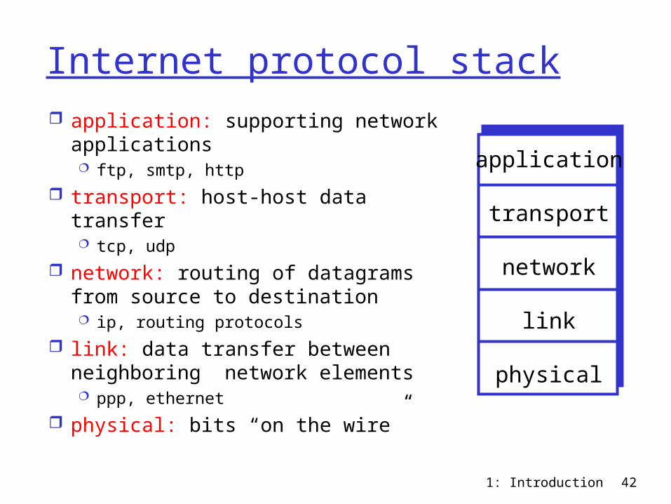
Internet protocol stack application: supporting network
applications ftp, smtp, http
transport: host-host data transfer tcp, udp
network: routing of datagrams from source to destination ip, routing protocols
link: data transfer between neighboring network elements ppp, ethernet
physical: bits “on the wire”
application
transport
network
link
physical
1: Introduction 43
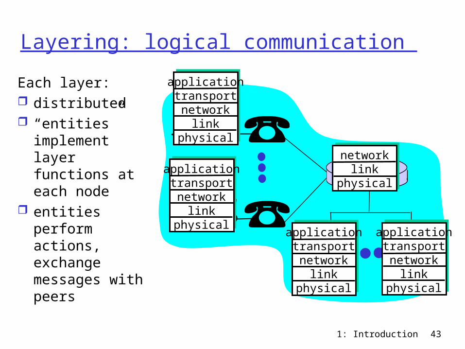
Layering: logical communication
applicationtransportnetwork
linkphysical
applicationtransportnetwork
linkphysical
applicationtransportnetwork
linkphysical
applicationtransportnetwork
linkphysical
networklink
physical
Each layer: distributed “entities”
implement layer functions at each node
entities perform actions, exchange messages with peers
1: Introduction 44
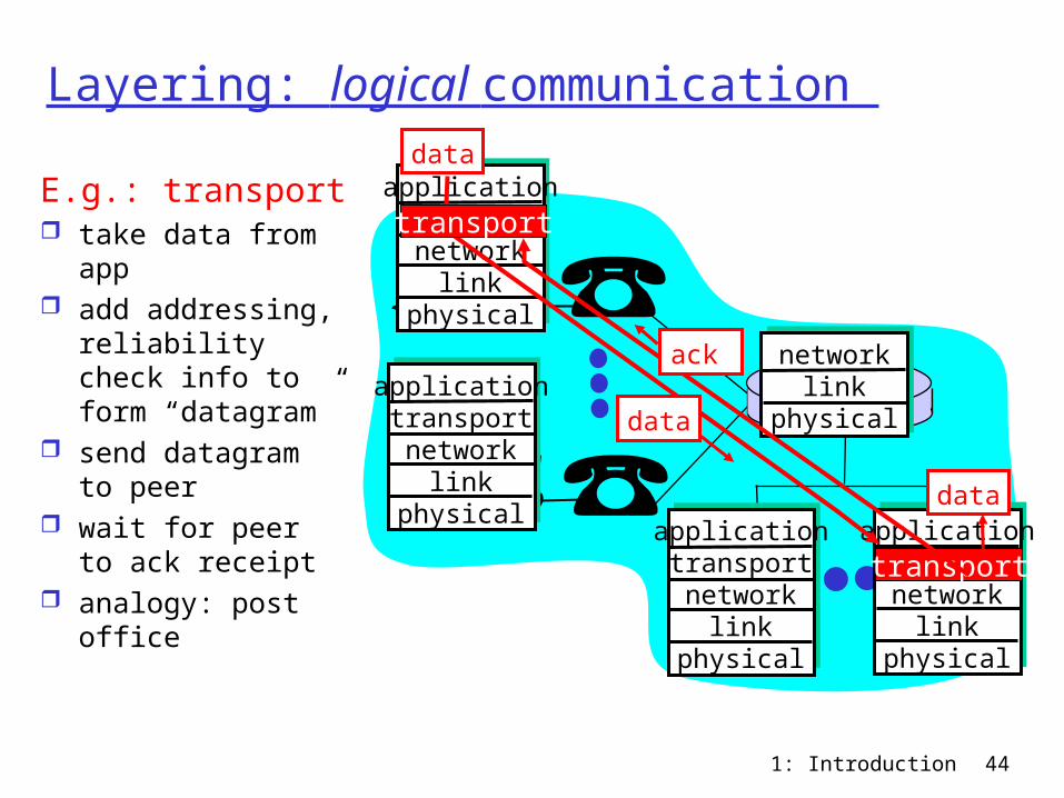
Layering: logical communication
applicationtransportnetwork
linkphysical
applicationtransportnetwork
linkphysical
applicationtransportnetwork
linkphysical
applicationtransportnetwork
linkphysical
networklink
physical
data
data
E.g.: transport take data from
app add addressing,
reliability check info to form “datagram”
send datagram to peer
wait for peer to ack receipt
analogy: post office
data
transport
transport
ack
1: Introduction 45
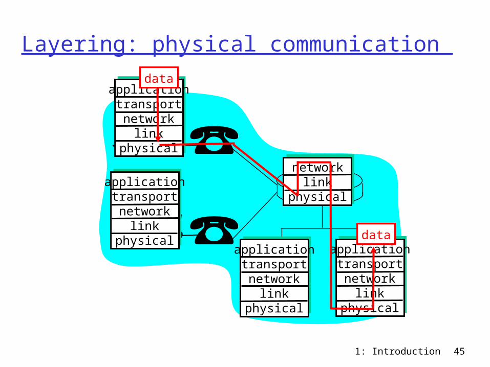
Layering: physical communication
applicationtransportnetwork
linkphysical
applicationtransportnetwork
linkphysical
applicationtransportnetwork
linkphysical
applicationtransportnetwork
linkphysical
networklink
physical
data
data
1: Introduction 46
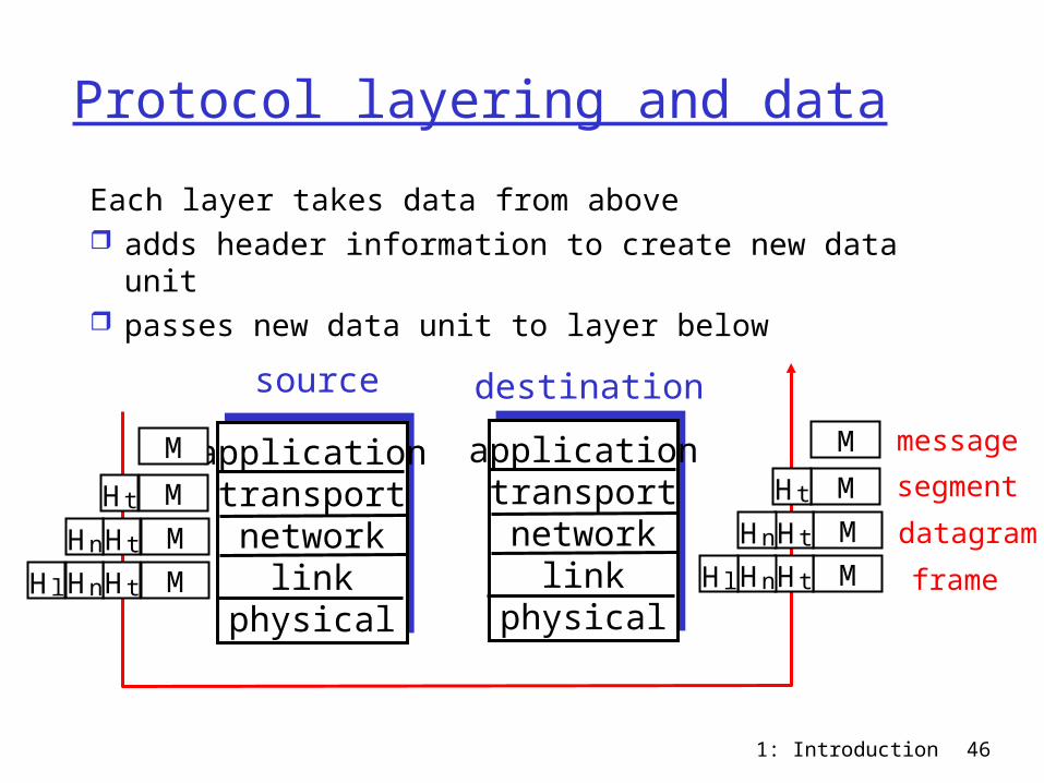
Protocol layering and data
Each layer takes data from above adds header information to create new data unit passes new data unit to layer below
applicationtransportnetwork
linkphysical
applicationtransportnetwork
linkphysical
source destination
M
M
M
M
Ht
HtHn
HtHnHl
M
M
M
M
Ht
HtHn
HtHnHl
message
segment
datagram
frame
1: Introduction 47
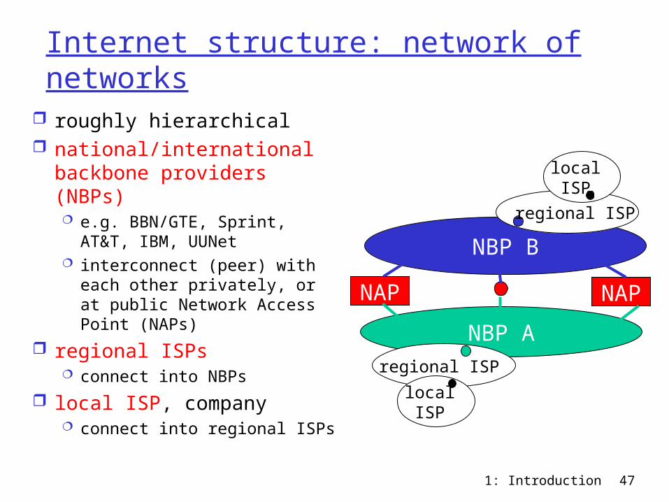
Internet structure: network of networks
roughly hierarchical national/international
backbone providers (NBPs) e.g. BBN/GTE, Sprint, AT&T,
IBM, UUNet interconnect (peer) with
each other privately, or at public Network Access Point (NAPs)
regional ISPs connect into NBPs
local ISP, company connect into regional ISPs
NBP A
NBP B
NAP NAP
regional ISP
regional ISP
localISP
localISP

1: Introduction 48
National Backbone Providere.g. Sprint US backbone network
1: Introduction 49
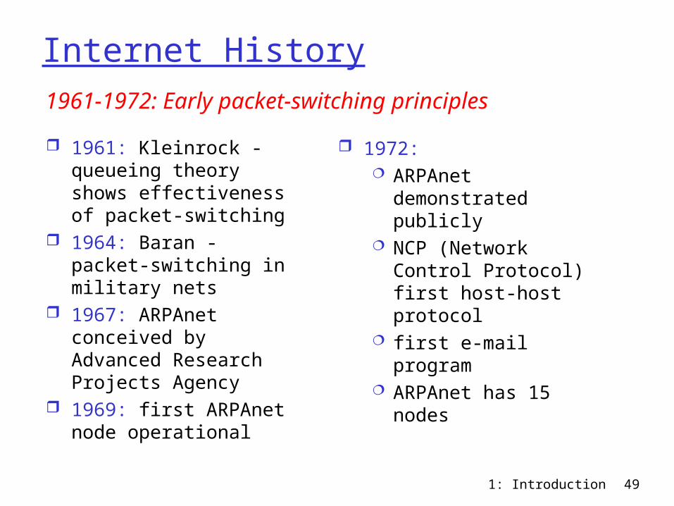
Internet History
1961: Kleinrock - queueing theory shows effectiveness of packet-switching
1964: Baran - packet-switching in military nets
1967: ARPAnet conceived by Advanced Research Projects Agency
1969: first ARPAnet node operational
1972: ARPAnet
demonstrated publicly NCP (Network Control
Protocol) first host-host protocol
first e-mail program ARPAnet has 15 nodes
1961-1972: Early packet-switching principles
1: Introduction 50
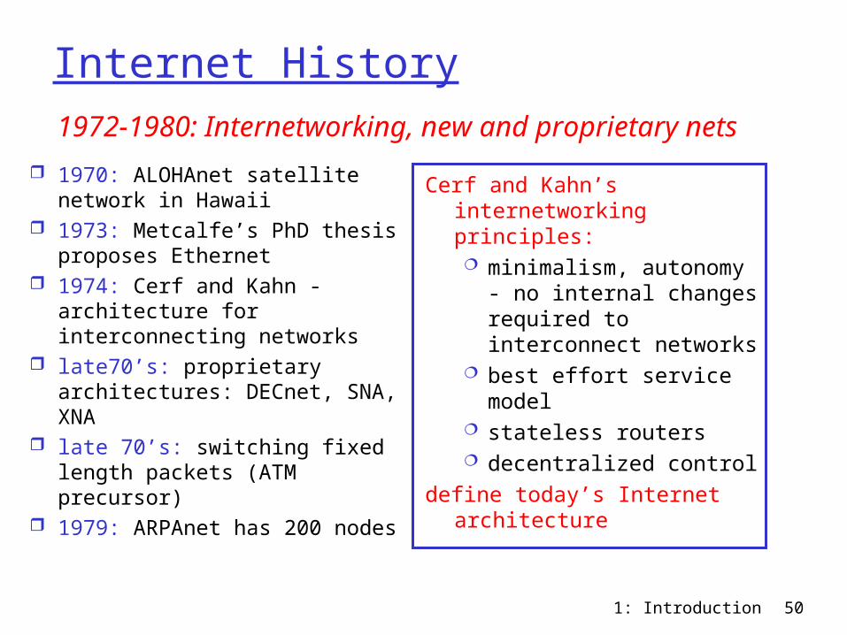
Internet History
1970: ALOHAnet satellite network in Hawaii
1973: Metcalfe’s PhD thesis proposes Ethernet
1974: Cerf and Kahn - architecture for interconnecting networks
late70’s: proprietary architectures: DECnet, SNA, XNA
late 70’s: switching fixed length packets (ATM precursor)
1979: ARPAnet has 200 nodes
Cerf and Kahn’s internetworking principles: minimalism, autonomy
- no internal changes required to interconnect networks
best effort service model
stateless routers decentralized control
define today’s Internet architecture
1972-1980: Internetworking, new and proprietary nets
1: Introduction 51
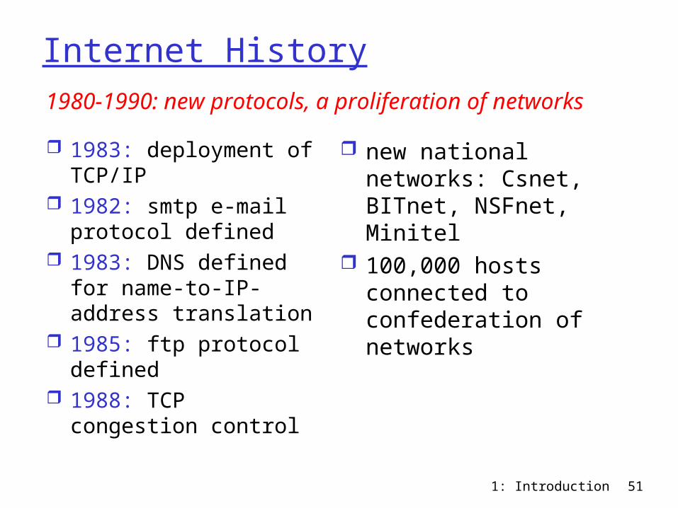
Internet History
1983: deployment of TCP/IP
1982: smtp e-mail protocol defined
1983: DNS defined for name-to-IP-address translation
1985: ftp protocol defined
1988: TCP congestion control
new national networks: Csnet, BITnet, NSFnet, Minitel
100,000 hosts connected to confederation of networks
1980-1990: new protocols, a proliferation of networks
1: Introduction 52
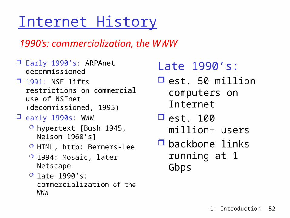
Internet History
Early 1990’s: ARPAnet decommissioned
1991: NSF lifts restrictions on commercial use of NSFnet (decommissioned, 1995)
early 1990s: WWW hypertext [Bush 1945,
Nelson 1960’s] HTML, http: Berners-Lee 1994: Mosaic, later
Netscape late 1990’s:
commercialization of the WWW
Late 1990’s: est. 50 million
computers on Internet
est. 100 million+ users
backbone links running at 1 Gbps
1990’s: commercialization, the WWW
1: Introduction 53
Introduction: Summary
Covered a “ton” of material! Internet overview what’s a protocol? network edge, core,
access network packet-switching
versus circuit-switching performance: loss, delay layering and service
models backbones, NAPs, ISPs history
You now have: context, overview,
“feel” of networking more depth, detail
later in course