Embed Size (px)
Citation preview
1
ITC242 – Introduction to Data Communications
Internet Operation
2
Last Week
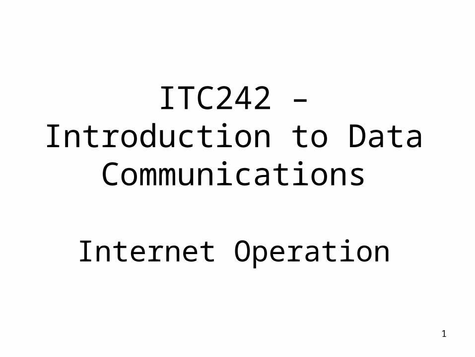
• SMTP - transmits messages to appropriate hosts via TCP, attempts to provide error-free transmission.
• MIME - Intended to resolve problems with SMTP, provides info about body of message, defines multiple content formats, and encodings
• HTTP - Stateless protocol, flexible format handling, Proxy, Gateway, Tunnel, Cache
• SIP - Manages real-time sessions over IP, enable Internet telephony/VoIP, HTTP-like request/response transaction model
3
Last Week
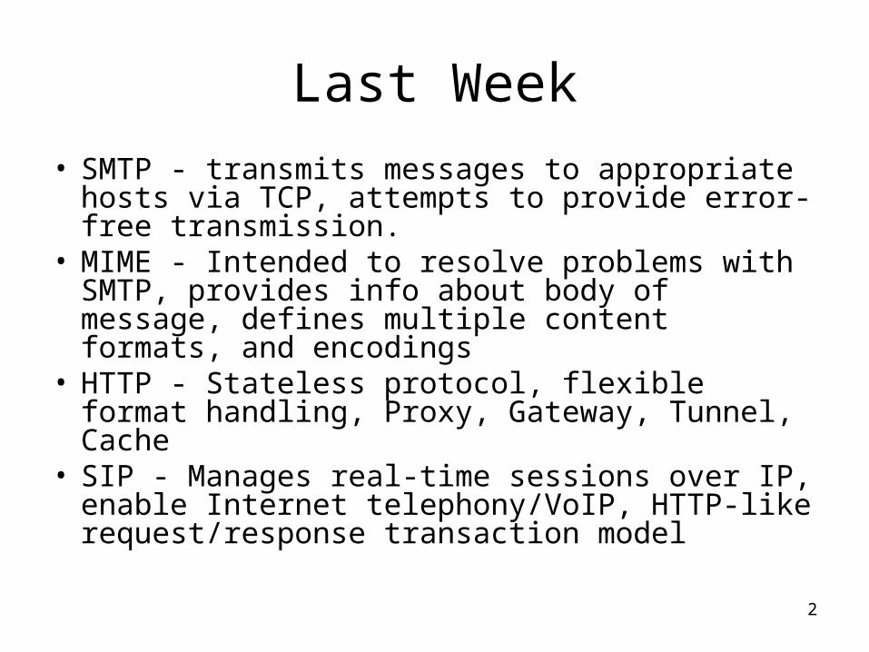
• Client/server - user-friendly client applications, centralized databases, open and modular applications, the network is fundamental
• Intranet - internet-based client/server technology within an organization, immensely successful
• Extranets – Extend intranet concept to outside community, e.g customers and suppliers, enables sharing of information between companies, TCP/IP enabled form of EDI.
4
Topic 8 – Internet Operation
Learning Objectives
• Describe the characteristics of an Internet Address
• Describe the different classes of IP addresses
• Explain the purpose of subnet masks.
5
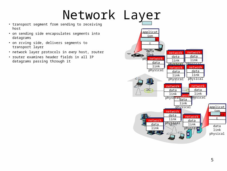
Network Layer• transport segment from sending to receiving host • on sending side encapsulates segments into
datagrams• on rcving side, delivers segments to transport layer• network layer protocols in every host, router• router examines header fields in all IP datagrams
passing through it
application
transportnetworkdata linkphysical
application
transportnetworkdata linkphysical
networkdata linkphysical network
data linkphysical
networkdata linkphysical
networkdata linkphysical
networkdata linkphysical
networkdata linkphysical
networkdata linkphysical
networkdata linkphysical
networkdata linkphysical
networkdata linkphysicalnetwork
data linkphysical
6
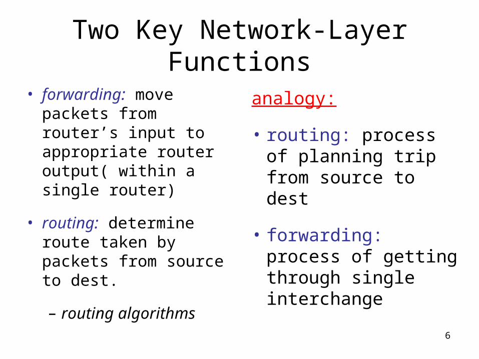
Two Key Network-Layer Functions
• forwarding: move packets from router’s input to appropriate router output( within a single router)
• routing: determine route taken by packets from source to dest.
– routing algorithms
analogy:
• routing: process of planning trip from source to dest
• forwarding: process of getting through single interchange
7
1
23
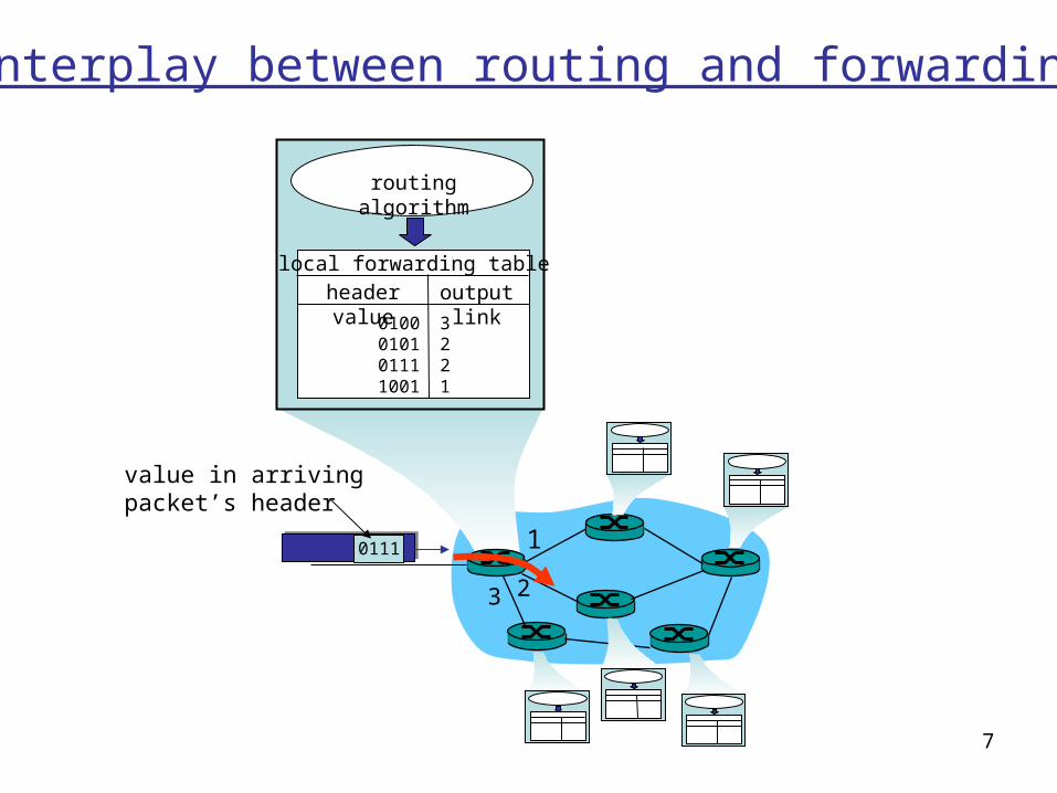
0111
value in arrivingpacket’s header
routing algorithm
local forwarding tableheader value output link
0100010101111001
3221
Interplay between routing and forwarding
8
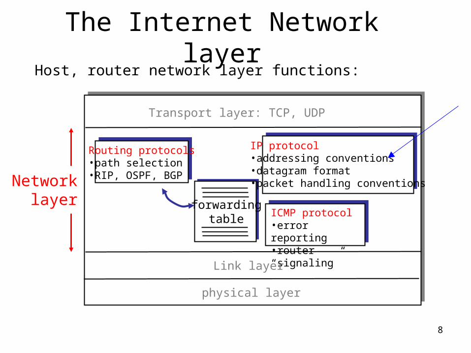
The Internet Network layer
forwardingtable
Host, router network layer functions:
Routing protocols•path selection•RIP, OSPF, BGP
IP protocol•addressing conventions•datagram format•packet handling conventions
ICMP protocol•error reporting•router “signaling”
Transport layer: TCP, UDP
Link layer
physical layer
Networklayer
9
IP protocol: IP Addresses
• IP (Version 4) addresses are 32 bits long
• IP addresses are hierarchical– They contain a network ID and a
host ID• IP addresses are assigned statically
or dynamically (e.g. DHCP)• IP (Version 6) addresses are 128 bits
long
10
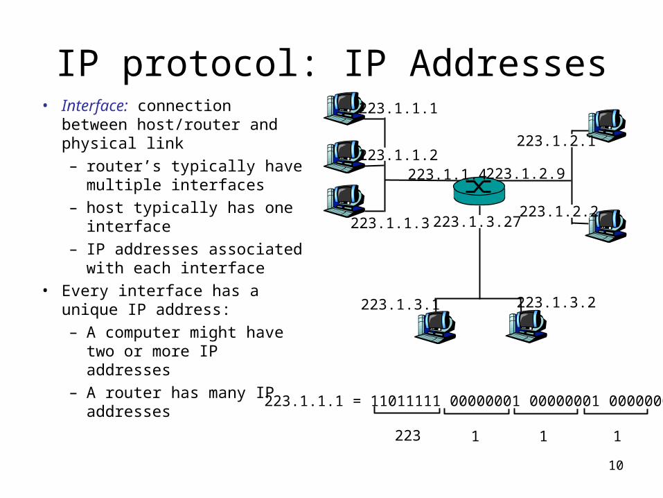
IP protocol: IP Addresses• Interface: connection between
host/router and physical link
– router’s typically have multiple interfaces
– host typically has one interface
– IP addresses associated with each interface
• Every interface has a unique IP address:
– A computer might have two or more IP addresses
– A router has many IP addresses
223.1.1.1
223.1.1.2
223.1.1.3
223.1.1.4 223.1.2.9
223.1.2.2
223.1.2.1
223.1.3.2223.1.3.1
223.1.3.27
223.1.1.1 = 11011111 00000001 00000001 00000001
223 1 11
11
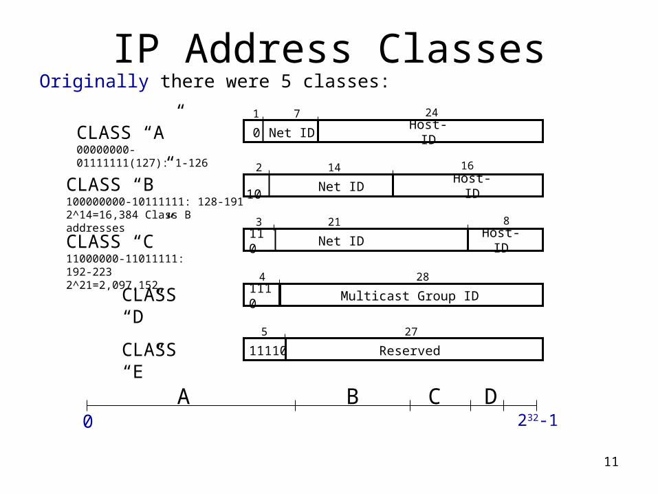
IP Address ClassesOriginally there were 5 classes:
CLASS “A” 00000000-01111111(127): 1-126
1 7
0 Net ID Host-ID
CLASS “B” 100000000-10111111: 128-1912^14=16,384 Class B addresses
10 Net ID Host-ID
24
2 14 16
CLASS “C” 11000000-11011111: 192-2232^21=2,097,152
110
Net ID Host-ID
3 21 8
CLASS “D”
1110
Multicast Group ID
4 28
CLASS “E” 11110 Reserved
5 27
A B C D0 232-1
12
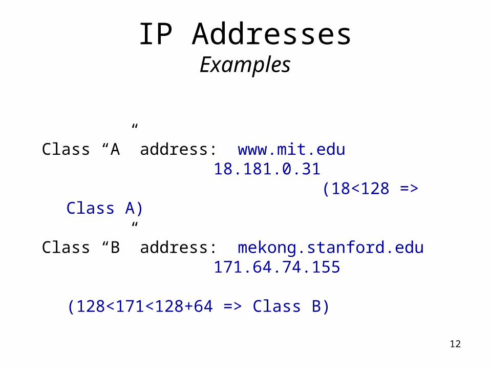
IP AddressesExamples
Class “A” address: www.mit.edu18.181.0.31
(18<128 => Class A)
Class “B” address: mekong.stanford.edu171.64.74.155
(128<171<128+64 => Class B)
13
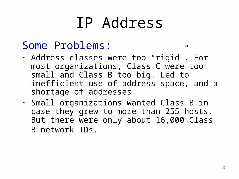
IP Address
Some Problems:• Address classes were too “rigid”. For most
organizations, Class C were too small and Class B too big. Led to inefficient use of address space, and a shortage of addresses.
• Small organizations wanted Class B in case they grew to more than 255 hosts. But there were only about 16,000 Class B network IDs.
14
Solution ?
Subnetting within an organization to subdivide the organization’s network ID.
15
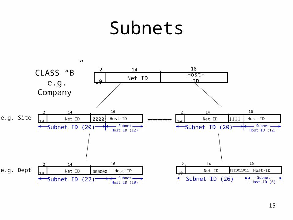
Subnets
CLASS “B”e.g.
Company
10 Net ID Host-ID
2 14 16
10 Net ID Host-ID
2 14 16
0000
Subnet ID (20) SubnetHost ID (12)
10 Net ID Host-ID
2 14 16
1111
Subnet ID (20) SubnetHost ID (12)
10 Net ID Host-ID
2 14 16
000000
Subnet ID (22) SubnetHost ID (10)
10 Net ID Host-ID
2 14 16
1111011011
Subnet ID (26) SubnetHost ID (6)
e.g. Site
e.g. Dept
16
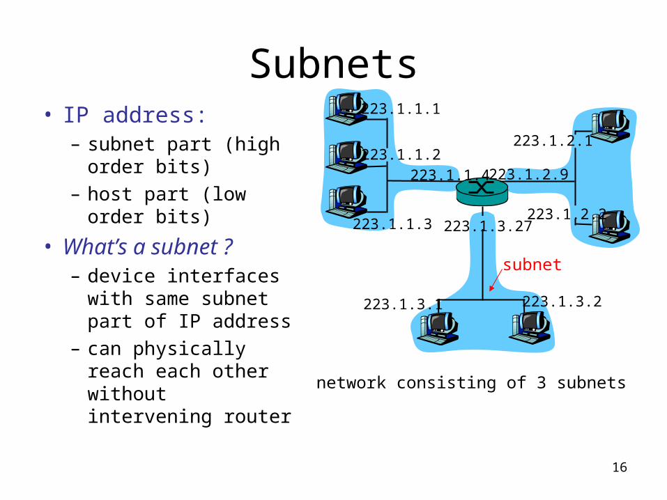
Subnets• IP address:
– subnet part (high order bits)
– host part (low order bits)
• What’s a subnet ?– device interfaces
with same subnet part of IP address
– can physically reach each other without intervening router
223.1.1.1
223.1.1.2
223.1.1.3
223.1.1.4 223.1.2.9
223.1.2.2
223.1.2.1
223.1.3.2223.1.3.1
223.1.3.27
network consisting of 3 subnets
subnet
17
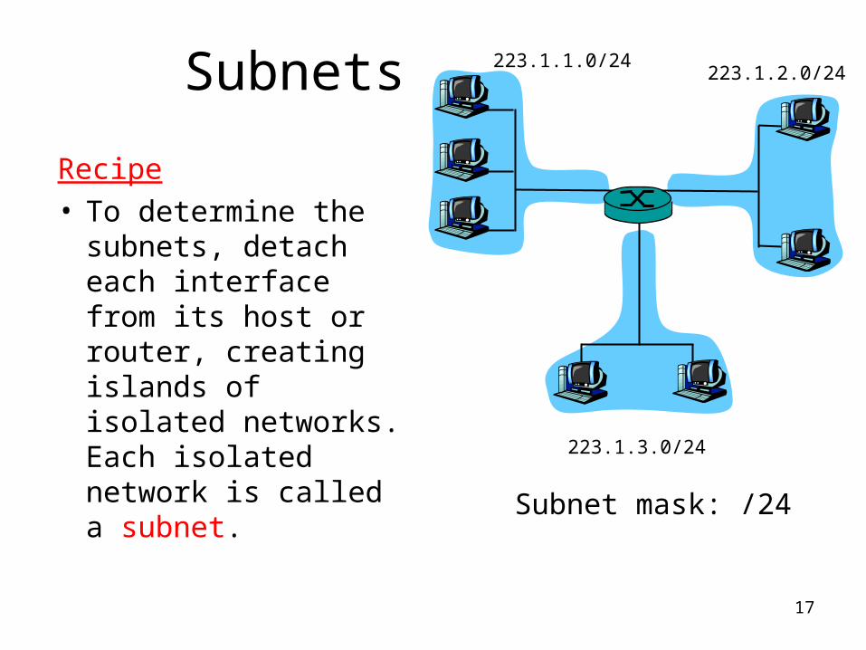
Subnets 223.1.1.0/24223.1.2.0/24
223.1.3.0/24
Recipe• To determine the
subnets, detach each interface from its host or router, creating islands of isolated networks. Each isolated network is called a subnet.
Subnet mask: /24
18
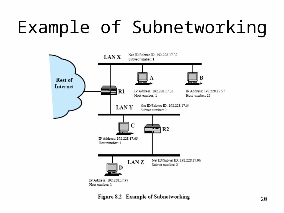
Subnets & Subnet Masks
• Allows for subdivision of internets within an organization
• Each LAN can have a subnet number, allowing routing among networks
• Host portion is partitioned into subnet and host numbers
19
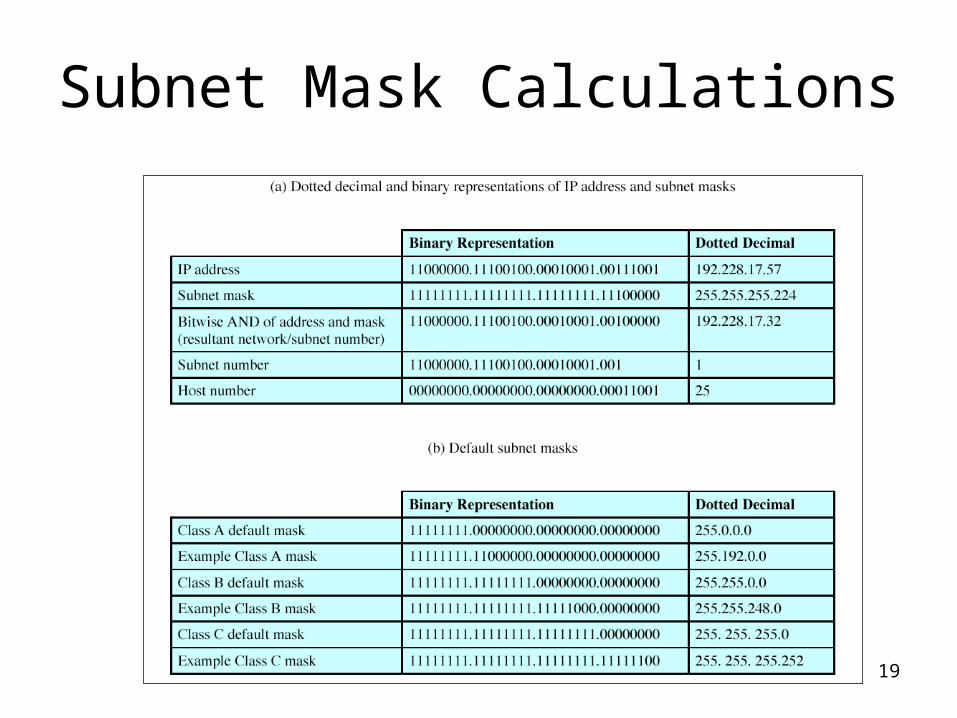
Subnet Mask Calculations
20
Example of Subnetworking
21
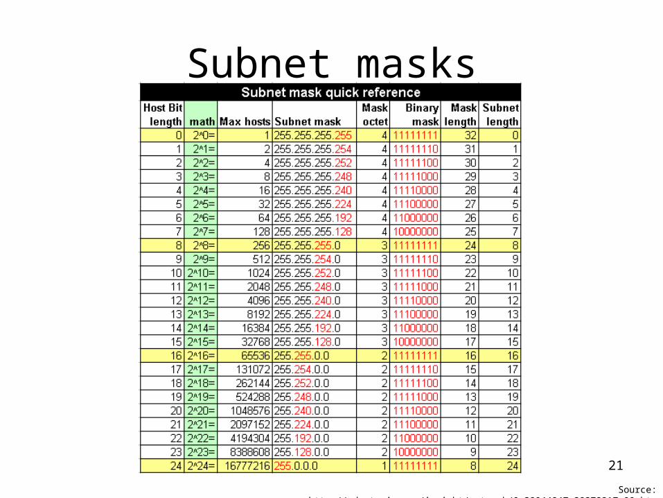
Subnet masks
Source: http://zdnetasia.com/insight/network/0,39044847,39372217,00.htm
22
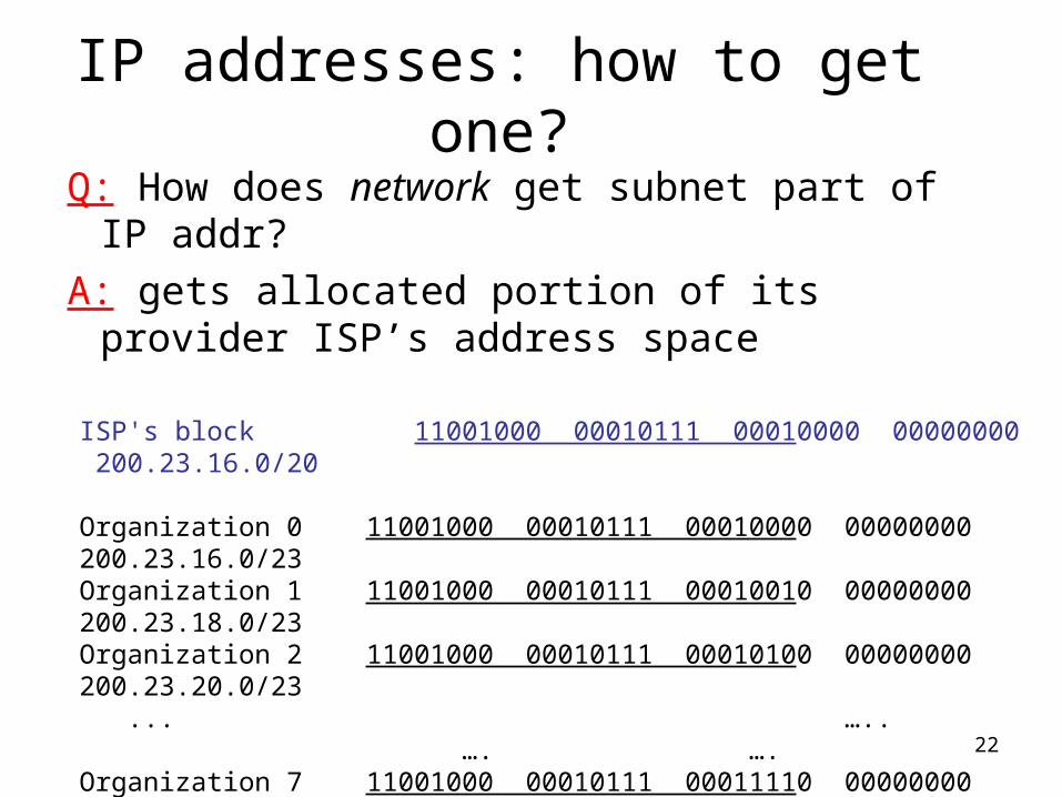
IP addresses: how to get one?
Q: How does network get subnet part of IP addr?
A: gets allocated portion of its provider ISP’s address space
ISP's block 11001000 00010111 00010000 00000000 200.23.16.0/20
Organization 0 11001000 00010111 00010000 00000000 200.23.16.0/23 Organization 1 11001000 00010111 00010010 00000000 200.23.18.0/23 Organization 2 11001000 00010111 00010100 00000000 200.23.20.0/23 ... ….. …. ….
Organization 7 11001000 00010111 00011110 00000000 200.23.30.0/23 a.b.c.d/x where x bits constitute the network portion ofThe IP address, and often referred to as the prefix of the address
23
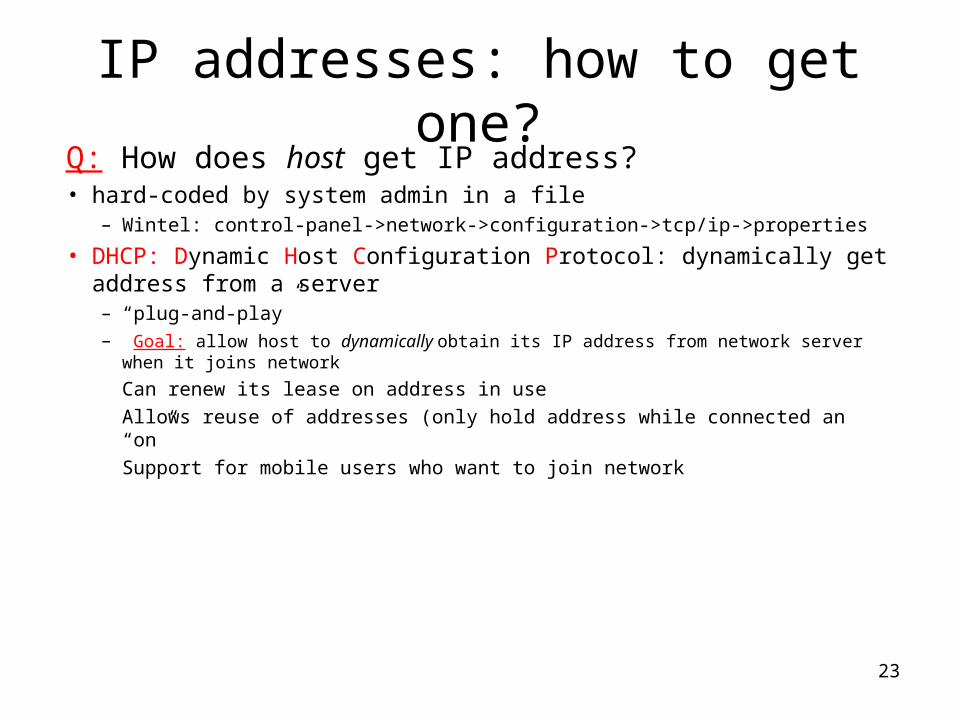
IP addresses: how to get one?Q: How does host get IP address?• hard-coded by system admin in a file
– Wintel: control-panel->network->configuration->tcp/ip->properties
• DHCP: Dynamic Host Configuration Protocol: dynamically get address from a server– “plug-and-play”– Goal: allow host to dynamically obtain its IP address from network server when it joins
network
Can renew its lease on address in use
Allows reuse of addresses (only hold address while connected an “on”
Support for mobile users who want to join network
24
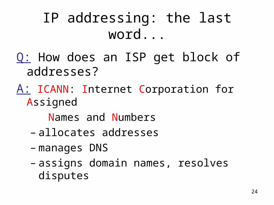
IP addressing: the last word...
Q: How does an ISP get block of addresses?
A: ICANN: Internet Corporation for Assigned
Names and Numbers– allocates addresses– manages DNS– assigns domain names, resolves disputes
25
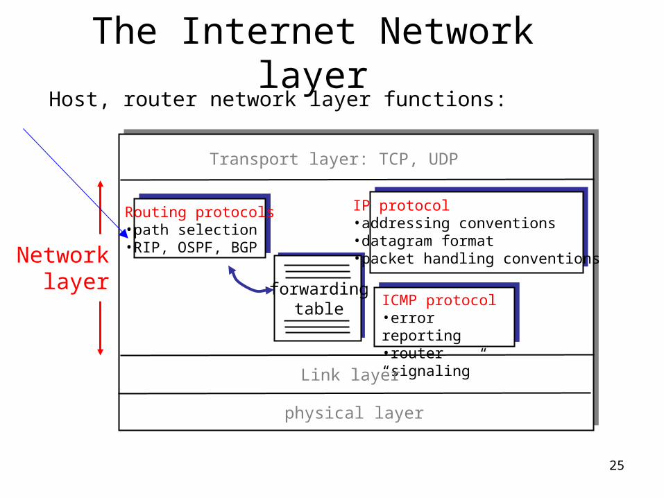
The Internet Network layer
forwardingtable
Host, router network layer functions:
Routing protocols•path selection•RIP, OSPF, BGP
IP protocol•addressing conventions•datagram format•packet handling conventions
ICMP protocol•error reporting•router “signaling”
Transport layer: TCP, UDP
Link layer
physical layer
Networklayer
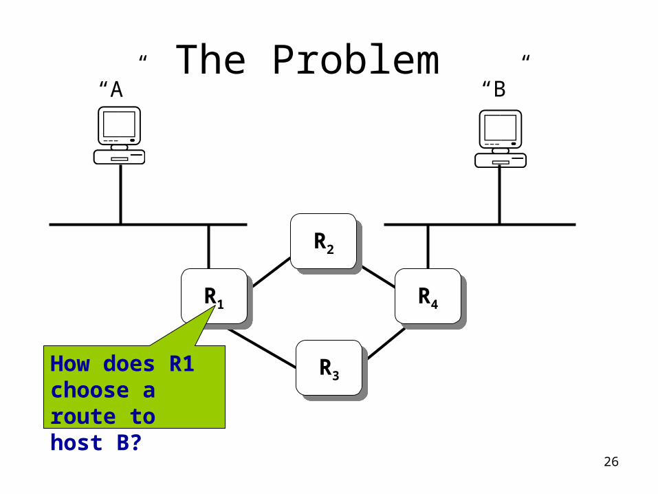
26
The Problem“A” “B”
R1R1
R2R2
R3R3
R4R4
How does R1 choose a route to host B?
27
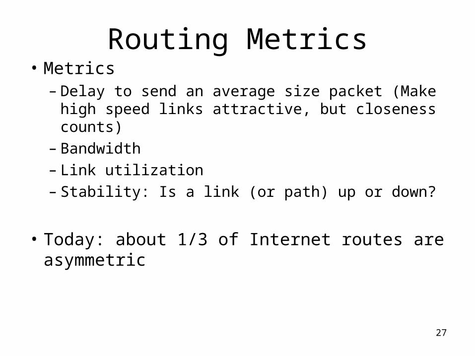
Routing Metrics• Metrics
– Delay to send an average size packet (Make high speed links attractive, but closeness counts)
– Bandwidth – Link utilization– Stability: Is a link (or path) up or down?
• Today: about 1/3 of Internet routes are asymmetric
28
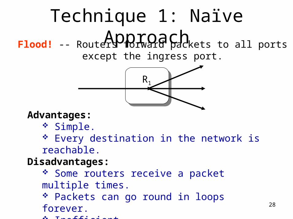
Technique 1: Naïve Approach
Advantages: Simple. Every destination in the network is reachable.
Disadvantages: Some routers receive a packet multiple times. Packets can go round in loops forever. Inefficient.
Flood! -- Routers forward packets to all portsexcept the ingress port.
R1
29
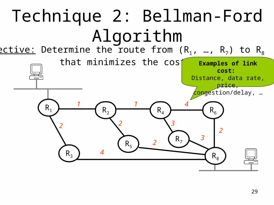
Technique 2: Bellman-Ford Algorithm
Objective: Determine the route from (R1, …, R7) to R8 that minimizes the cost.
R5
R3
R7
R6R4R2R1
1 1 4
2
4
2 2 3
23
R8
Examples of link cost: Distance, data rate, price,
congestion/delay, …
30
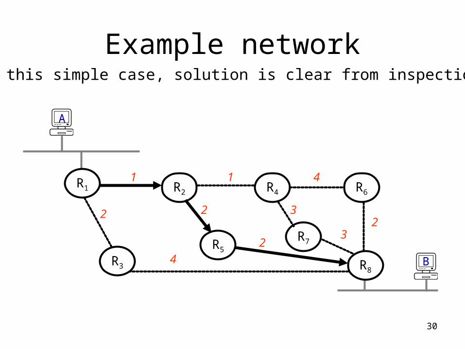
Example networkIn this simple case, solution is clear from inspection
R7
R6R4R2R1
1 1 4
2
4
2 2 3
23
R8
A
BR5
R3
31
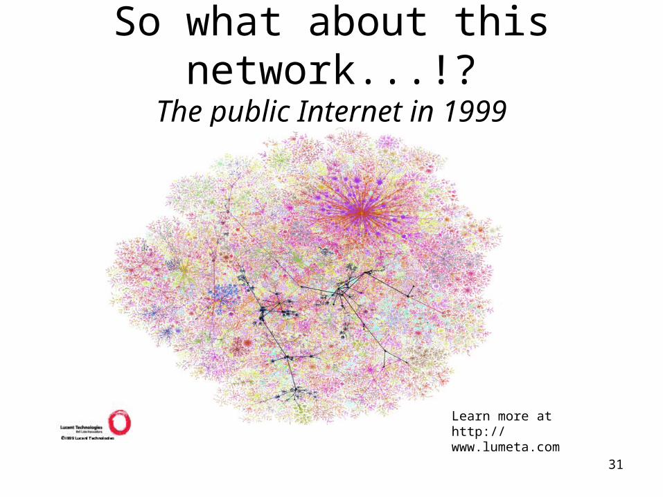
So what about this network...!?The public Internet in 1999
Learn more athttp://www.lumeta.com
32
Technique 3: Dijkstra’s Shortest Path First Algorithm
• The algorithm identifies the least costly paths between source and destination, given that costs are assigned to the edges.
• Routers send out update messages whenever the state of a link changes. Hence the name: “Link State” algorithm.
• Each router calculates lowest cost path to all others, starting from itself.
33
The problem
• How to route in the Internet?
34
Internet Routing Protocols
• Responsible for receiving and forwarding packets between interconnected networks
• Must dynamically adapt to changing network conditions
35
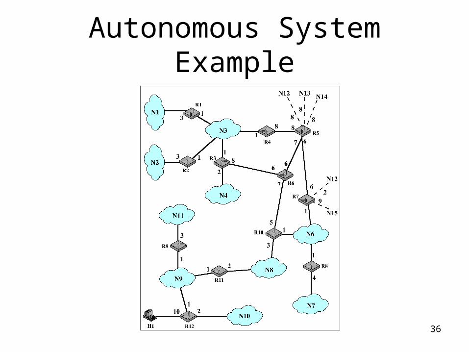
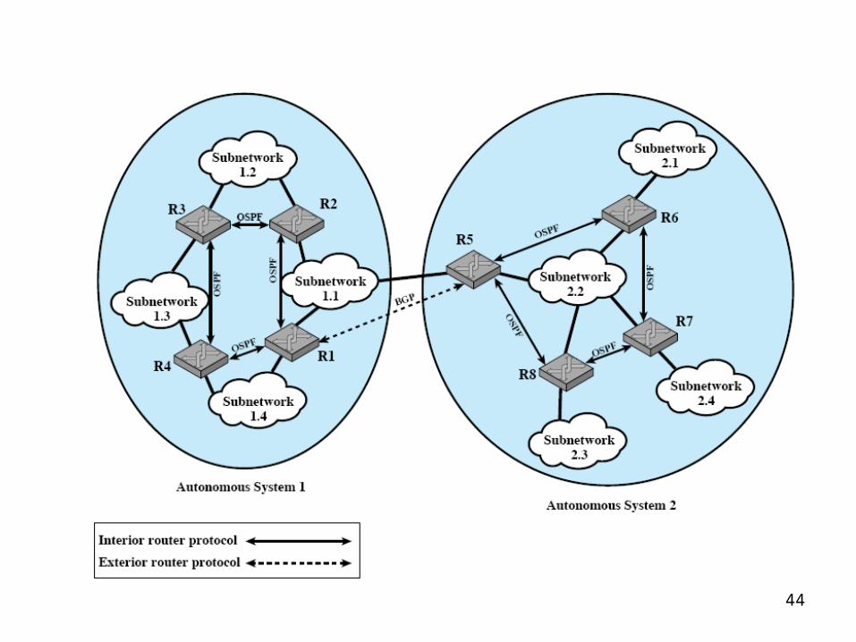
Autonomous Systems (AS)
• Key characteristics– Set of routers and networks managed by
single organization– group of routers exchanging information via a
common routing protocol– connected (in a graph-theoretic sense); that is,
there is a path between any pair of nodes
36
Autonomous System Example
37
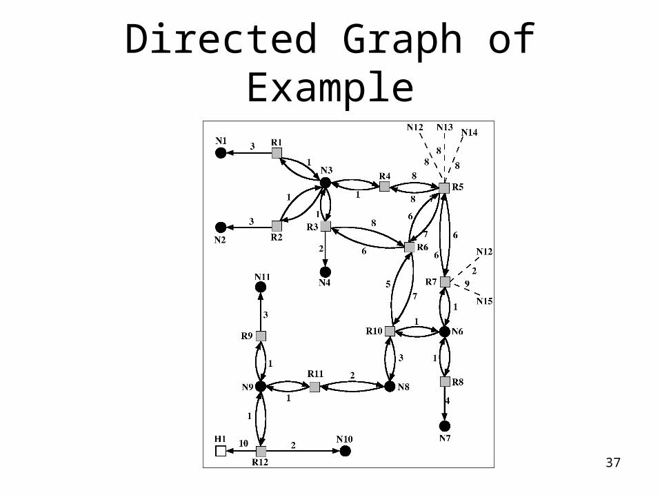
Directed Graph of Example
38
Routing in the Internet
The Internet uses hierarchical routing• The Internet is split into Autonomous Systems (AS’s)• Within an AS, the administrator chooses an Interior
Gateway Protocol (IGP) Examples of IGPs: RIP (rfc 1058), OSPF (rfc 1247).
• Between AS’s, the Internet uses an Exterior Gateway Protocol AS’s today use the Border Gateway Protocol, BGP-4
(rfc 1771)
39
Routing in the InternetThe Internet uses hierarchical
routing• The Internet is split into Autonomous
Systems (AS)
• aggregate routers into regions, AS
• routers in same AS run same routing protocol– “intra-AS” routing protocol
• routers in different AS can run different intra-AS routing protocol
Gateway router• Direct link to router in
another AS
40
3b
1d
3a
1c2aAS3
AS1
AS21a
2c2b
1b
Intra-ASRouting algorithm
Inter-ASRouting algorithm
Forwardingtable
3c
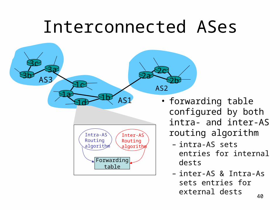
Interconnected ASes
• forwarding table configured by both intra- and inter-AS routing algorithm– intra-AS sets entries for
internal dests
– inter-AS & Intra-As sets entries for external dests
41
3b
1d
3a
1c2aAS3
AS1
AS21a
2c2b
1b
3c
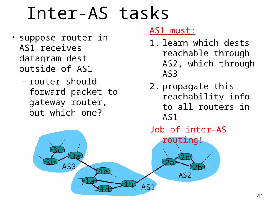
Inter-AS tasks• suppose router in AS1
receives datagram dest outside of AS1– router should
forward packet to gateway router, but which one?
AS1 must:
1. learn which dests reachable through AS2, which through AS3
2. propagate this reachability info to all routers in AS1
Job of inter-AS routing!
42
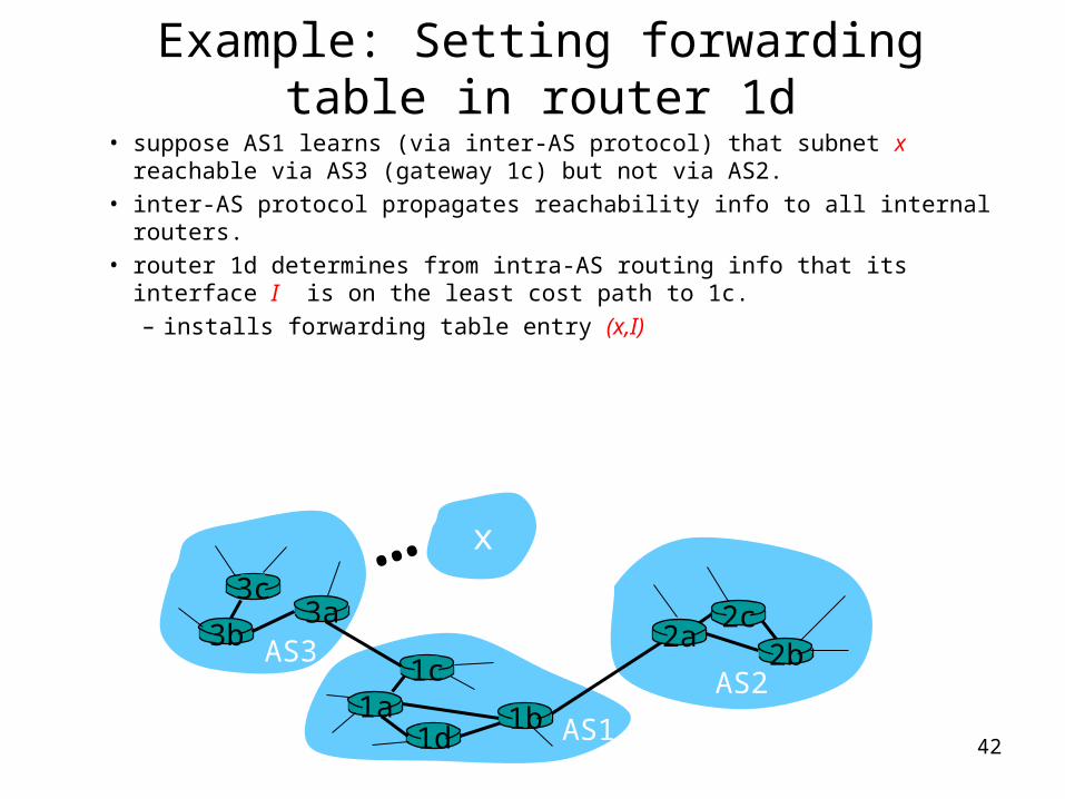
Example: Setting forwarding table in router 1d
• suppose AS1 learns (via inter-AS protocol) that subnet x reachable via AS3 (gateway 1c) but not via AS2.
• inter-AS protocol propagates reachability info to all internal routers.• router 1d determines from intra-AS routing info that its interface I is on
the least cost path to 1c.– installs forwarding table entry (x,I)
3b
1d
3a
1c2aAS3
AS1
AS21a
2c2b
1b
3c
x…
43
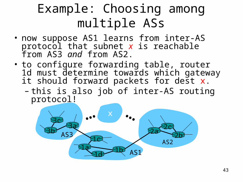
Example: Choosing among multiple ASs
• now suppose AS1 learns from inter-AS protocol that subnet x is reachable from AS3 and from AS2.
• to configure forwarding table, router 1d must determine towards which gateway it should forward packets for dest x. – this is also job of inter-AS routing protocol!
3b
1d
3a
1c2aAS3
AS1
AS21a
2c2b
1b
3cx… …
44
45
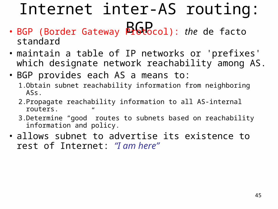
Internet inter-AS routing: BGP• BGP (Border Gateway Protocol): the de facto
standard• maintain a table of IP networks or 'prefixes' which
designate network reachability among AS. • BGP provides each AS a means to:
1. Obtain subnet reachability information from neighboring ASs.2. Propagate reachability information to all AS-internal routers.3. Determine “good” routes to subnets based on reachability
information and policy.
• allows subnet to advertise its existence to rest of Internet: “I am here”
46
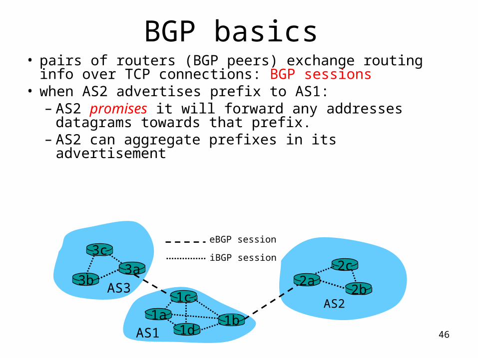
BGP basics• pairs of routers (BGP peers) exchange routing info
over TCP connections: BGP sessions• when AS2 advertises prefix to AS1:
– AS2 promises it will forward any addresses datagrams towards that prefix.
– AS2 can aggregate prefixes in its advertisement
3b
1d
3a
1c2aAS3
AS1
AS21a
2c
2b
1b
3ceBGP session
iBGP session
47
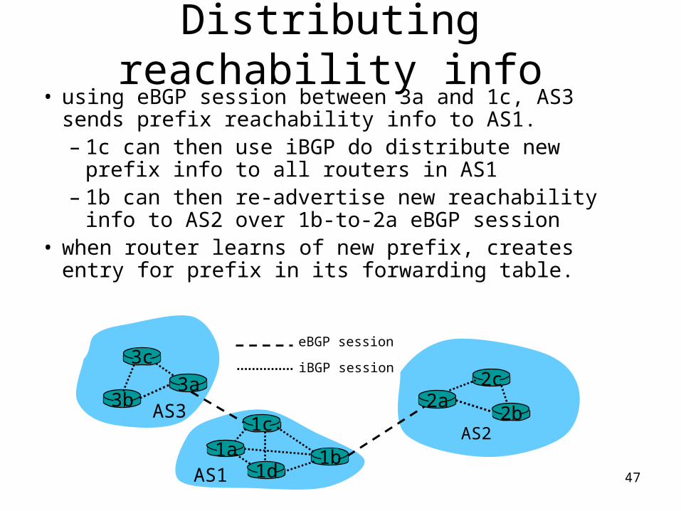
Distributing reachability info• using eBGP session between 3a and 1c, AS3
sends prefix reachability info to AS1.– 1c can then use iBGP do distribute new
prefix info to all routers in AS1– 1b can then re-advertise new reachability info
to AS2 over 1b-to-2a eBGP session• when router learns of new prefix, creates entry
for prefix in its forwarding table.
3b
1d
3a
1c2aAS3
AS1
AS21a
2c
2b
1b
3ceBGP session
iBGP session
48
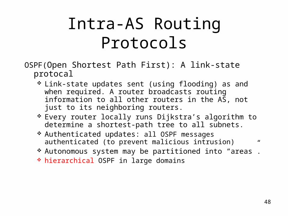
Intra-AS Routing Protocols
OSPF(Open Shortest Path First): A link-state protocal Link-state updates sent (using flooding) as and when
required. A router broadcasts routing information to all other routers in the AS, not just to its neighboring routers.
Every router locally runs Dijkstra’s algorithm to determine a shortest-path tree to all subnets.
Authenticated updates: all OSPF messages authenticated (to prevent malicious intrusion)
Autonomous system may be partitioned into “areas”. hierarchical OSPF in large domains
49
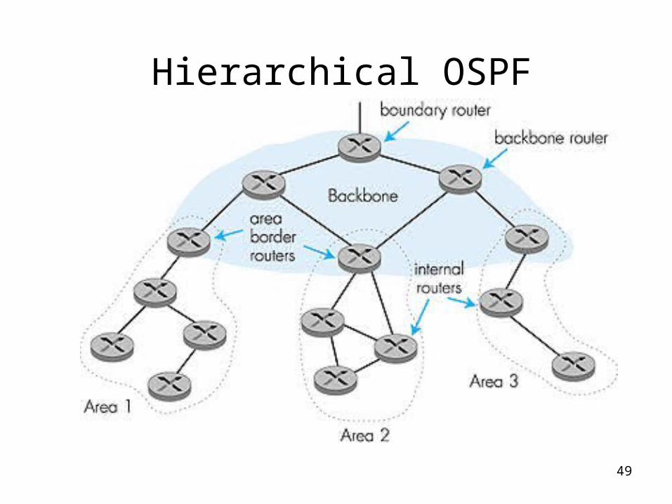
Hierarchical OSPF
50
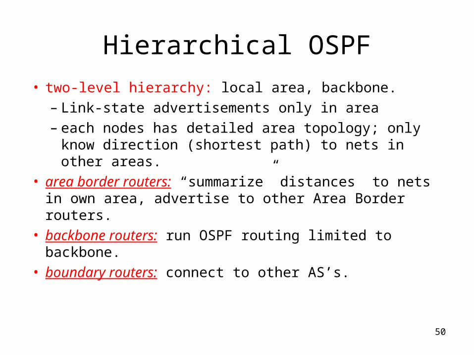
Hierarchical OSPF
• two-level hierarchy: local area, backbone.– Link-state advertisements only in area – each nodes has detailed area topology; only know
direction (shortest path) to nets in other areas.• area border routers: “summarize” distances to nets in
own area, advertise to other Area Border routers.• backbone routers: run OSPF routing limited to
backbone.• boundary routers: connect to other AS’s.
51
Topic 9 – LAN architecture and protocols
Learning Objectives
• Define the various types of Local Area Networks (LANs)
• Discuss the different types of transmission media commonly used in LANs.
52
Backend & Storage Area Networks
• “Computer room networks”
• High data rate
• High-speed interface
• Distributed access
• Limited distance
• Limited number of devices
53
Storage Area Network (SAN)
• A separate network to handle storage needs
• Decouples storage tasks from specific servers
• Creates a shared storage facility across a high-speed network
54
High-Speed Office Networks
• Increased processing and transfer requirements in many graphics-intensive applications now require significantly higher transfer rates
• Decreased cost of storage space leads to program and file bloat, increased need for transfer capacity
• Typical office LAN runs at 10Mbps, high-speed alternatives run at 100Mbps, 1 Gbps, 10Gbps
55
Backbone Local Networks
• Used instead of single-LAN strategy
• Better reliability
• Higher capacity
• Lower cost
56
Factory Networks
• High capacity
• Ability to handle a variety of data traffic
• Large geographic extent
• High reliability
• Ability to specify and control transmission delays
57
Tiered LANs
• Cost of attachment to a LAN tends to increase with data rate
• Alternative to connecting all devices is to have multiple tiers
• Multiple advantages– Higher reliability– Greater capacity (less saturation)– Better distribution of costs based on need
58
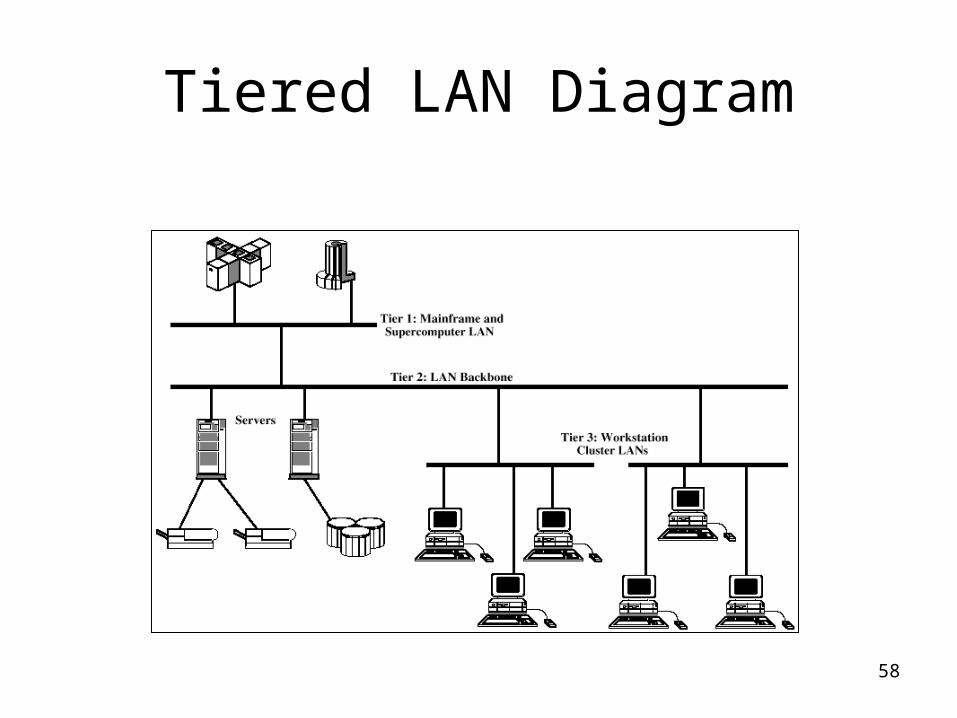
Tiered LAN Diagram
59
The Media
• The Transmission Media is the physical path between transmitter and receiver
• Can be classified as guided or unguided
• For both transmission is with electromagnetic waves.
• Guided Media – waves are guided along a solid medium, e.g. cables
• Unguided Media – wireless transmission
60
Guided Media
• Twisted Pair Wires
• Coaxial Cable
• Fibre Optic Cable
61
Twisted Pair Wires
• Consists of two insulated copper wires arranged in a regular spiral pattern to minimize the electromagnetic interference between adjacent pairs
• Often used at customer facilities and also over distances to carry voice as well as data communications
• Low frequency transmission medium
62
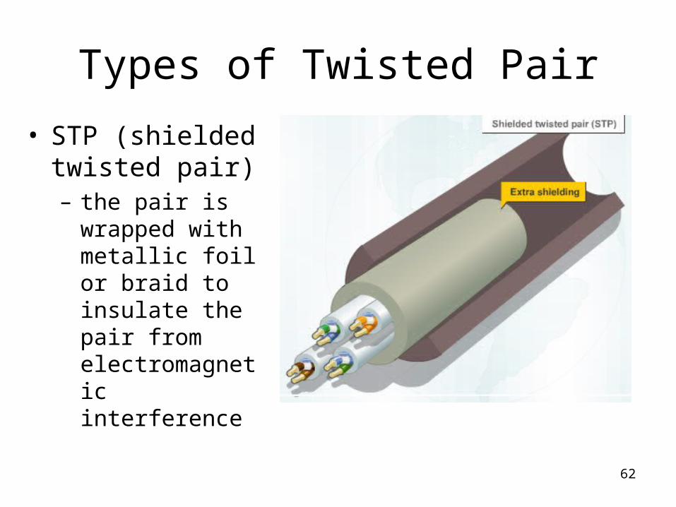
Types of Twisted Pair
• STP (shielded twisted pair)– the pair is
wrapped with metallic foil or braid to insulate the pair from electromagnetic interference
63
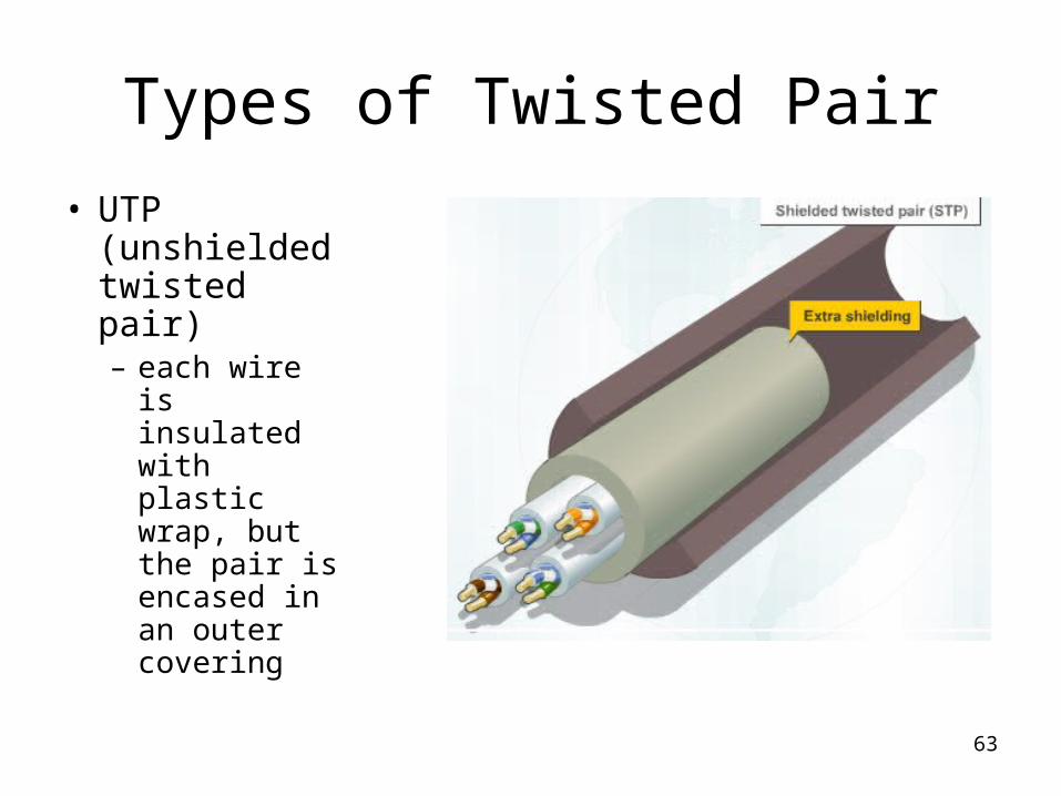
Types of Twisted Pair
• UTP (unshielded twisted pair)– each wire is
insulated with plastic wrap, but the pair is encased in an outer covering
64
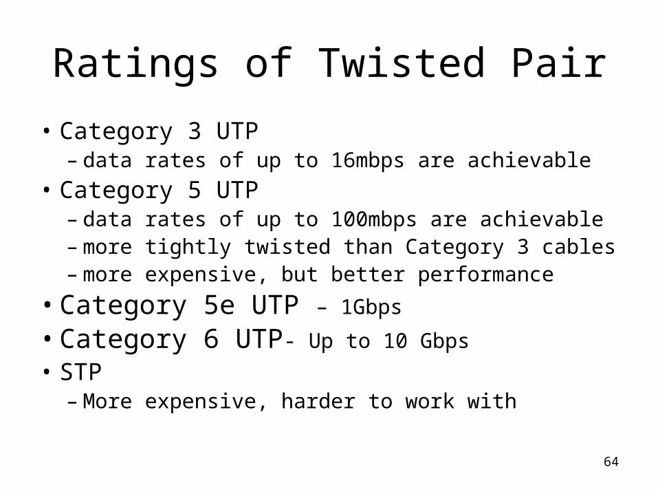
Ratings of Twisted Pair
• Category 3 UTP– data rates of up to 16mbps are achievable
• Category 5 UTP– data rates of up to 100mbps are achievable– more tightly twisted than Category 3 cables– more expensive, but better performance
• Category 5e UTP – 1Gbps
• Category 6 UTP- Up to 10 Gbps
• STP– More expensive, harder to work with
65
Twisted Pair Advantages
• Inexpensive and readily available
• Flexible and light weight
• Easy to work with and install
66
Twisted Pair Disadvantages
• Susceptibility to interference and noise
• Attenuation problem– For analog, repeaters needed every 5-6km– For digital, repeaters needed every 2-3km
67
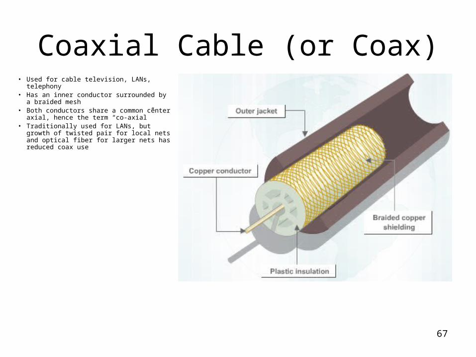
Coaxial Cable (or Coax)• Used for cable television, LANs,
telephony• Has an inner conductor surrounded by a
braided mesh• Both conductors share a common center
axial, hence the term “co-axial”• Traditionally used for LANs, but growth of
twisted pair for local nets and optical fiber for larger nets has reduced coax use
68
Fiber Optic Cable
• Fiber optic cable is used for modular light transmission. Instead of transmitting electrical signals, it transmits pulses of light that represent bits.
• Advantages– Greater capacity– Smaller size/lighter weight– Lower attenuation– Electromagnetic isolation
• Operate in the range of about 1014 to 1015 Hz; (portions of the infrared and visible spectrums)
69
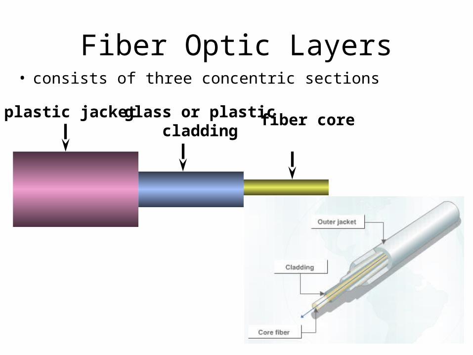
plastic jacket glass or plasticcladding
fiber core
Fiber Optic Layers• consists of three concentric sections
70
Fiber Optic Types• single-mode fiber
– A single-mode cable uses lasers to generate light. It allows just one mode of light to pass through it at a time, but is capable of greater bandwidth and greater distances than multimode cable. It is more expensive than multimode cable, and has a maximum cable length of 60 kilometers
• multimode fiber– Multimode cable allows multiple light modes to pass along
its fibers. Favored in workgroup applications, multimode cable uses light emitting diodes (LEDs) to generate light. A multimode fiber optic cable cannot exceed 2 kilometers.
71
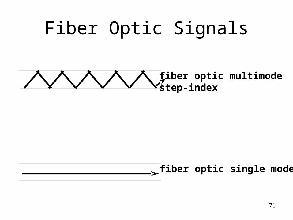
fiber optic multimodestep-index
fiber optic single mode
Fiber Optic Signals
72
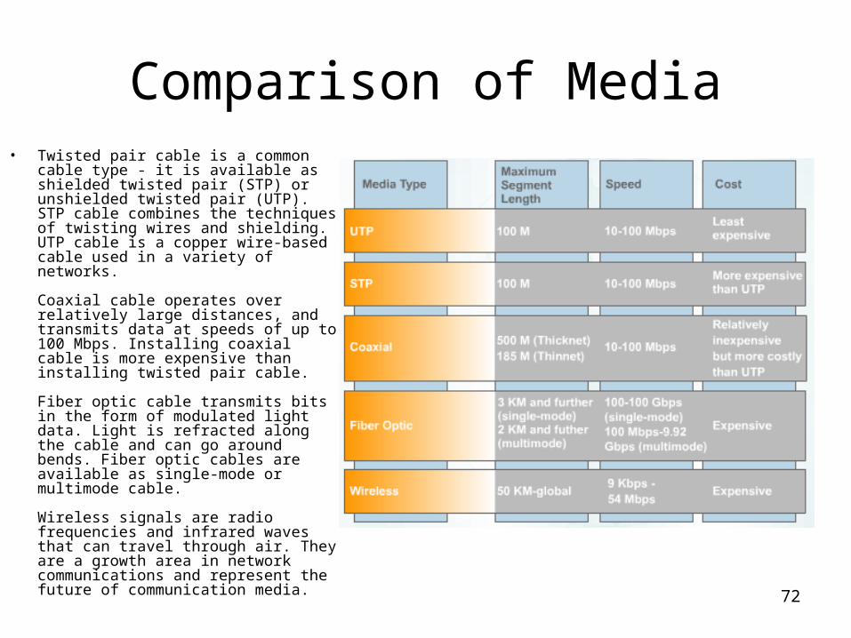
Comparison of Media• Twisted pair cable is a common cable
type - it is available as shielded twisted pair (STP) or unshielded twisted pair (UTP). STP cable combines the techniques of twisting wires and shielding. UTP cable is a copper wire-based cable used in a variety of networks.
Coaxial cable operates over relatively large distances, and transmits data at speeds of up to 100 Mbps. Installing coaxial cable is more expensive than installing twisted pair cable.
Fiber optic cable transmits bits in the form of modulated light data. Light is refracted along the cable and can go around bends. Fiber optic cables are available as single-mode or multimode cable.
Wireless signals are radio frequencies and infrared waves that can travel through air. They are a growth area in network communications and represent the future of communication media.