Embed Size (px)
Citation preview
1
Memory-Based Rack Area Networking
Presented by: Cheng-Chun TuAdvisor: Tzi-cker ChiuehStony Brook University &
Industrial Technology Research Institute
2
Disaggregated Rack Architecture
Rack becomes a basic building block for cloud-scale data centers
CPU/memory/NICs/Disks embedded in self-contained server
Disk pooling in a rackNIC/Disk/GPU pooling in a rackMemory/NIC/Disk pooling in a rack
Rack disaggregationPooling of HW resources for global allocation and independent upgrade cycle for each resource type
3
Requirements
High-Speed NetworkI/O Device Sharing Direct I/O Access from VM High AvailabilityCompatible with existing technologies
4
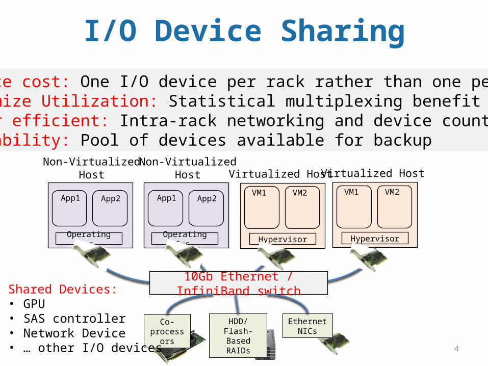
• Reduce cost: One I/O device per rack rather than one per host • Maximize Utilization: Statistical multiplexing benefit• Power efficient: Intra-rack networking and device count• Reliability: Pool of devices available for backup
Operating Sys.
App1 App2
Non-VirtualizedHost
Hypervisor
VM1 VM2
Virtualized Host
Operating Sys.
App1 App2
Non-VirtualizedHost
Hypervisor
VM1 VM2
Virtualized Host
Switch10Gb Ethernet / InfiniBand switch
Co-processors
HDD/Flash-Based RAIDs
Ethernet NICs
Shared Devices:• GPU• SAS controller• Network Device• … other I/O devices
I/O Device Sharing
5
PCI Express
PCI Express is a promising candidate Gen3 x 16 lane = 128Gbps with low latency (150ns per hop) New hybrid top-of-rack (TOR) switch consists of PCIe ports and Ethernet ports
Universal interface for I/O Devices Network , storage, graphic cards, etc. Native support for I/O device sharing
I/O VirtualizationSR-IOV enables direct I/O device access from VMMulti-Root I/O Virtualization (MRIOV)
6
Challenges
Single Host (Single-Root) Model
Not designed for interconnecting/sharing amount
multiple hosts (Multi-Root)
Share I/O devices securely and
efficiently
Support socket-based applications over
PCIe
Direct I/O device access from guest
OSes
7
Observations
PCIe: a packet-based network (TLP)But all about it is memory addresses
Basic I/O Device Access Model Device ProbingDevice-Specific ConfigurationDMA (Direct Memory Access)Interrupt (MSI, MSI-X)
Everything is through memory access!Thus, “Memory-Based” Rack Area Networking
8
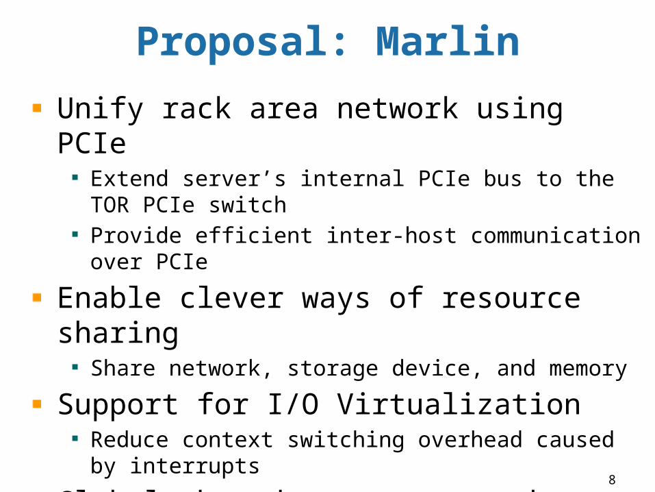
Proposal: Marlin
Unify rack area network using PCIeExtend server’s internal PCIe bus to the TOR PCIe switchProvide efficient inter-host communication over PCIe
Enable clever ways of resource sharingShare network, storage device, and memory
Support for I/O VirtualizationReduce context switching overhead caused by interrupts
Global shared memory networkNon-cache coherent, enable global communication through direct load/store operation
9
INTRODUCTION
PCIe Architecture, SR-IOV, MR-IOV, and NTB (Non-Transparent Bridge)
10
CPU #n
PCIe Root Complex
PCIe Endpoint
PCIe TBSwitch
PCIe Endpoint
PCIe TBSwitch
PCIe TBSwitch
PCIe Endpoint3
PCIe Endpoint1
PCIe Endpoint2
CPU #nCPU #n
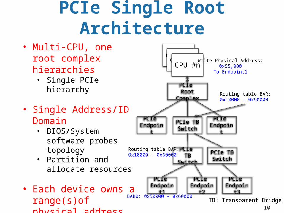
• Multi-CPU, one root complex hierarchies• Single PCIe hierarchy
• Single Address/ID Domain• BIOS/System software
probes topology• Partition and allocate
resources
• Each device owns a range(s)of physical address• BAR addresses, MSI-X,
and device ID • Strict hierarchical
routing
TB: Transparent Bridge
PCIe Single Root Architecture
Routing table BAR:0x10000 – 0x90000
Routing table BAR:0x10000 – 0x60000
BAR0: 0x50000 - 0x60000
Write Physical Address:0x55,000
To Endpoint1
11
Single Host I/O Virtualization
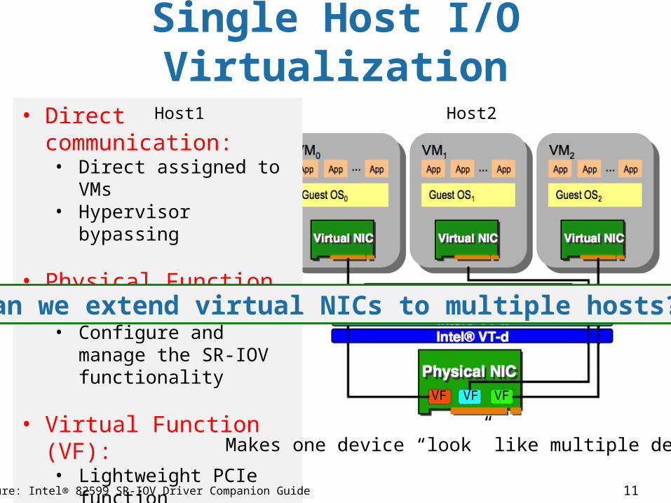
• Direct communication:• Direct assigned to VMs• Hypervisor bypassing
• Physical Function (PF):• Configure and manage
the SR-IOV functionality
• Virtual Function (VF):• Lightweight PCIe
function• With resources
necessary for data movement
• Intel VT-x and VT-d• CPU/Chipset support
for VMs and devices
Figure: Intel® 82599 SR-IOV Driver Companion Guide
Makes one device “look” like multiple devices
VF VF VF
Can we extend virtual NICs to multiple hosts?
Host1 Host2 Host3
12
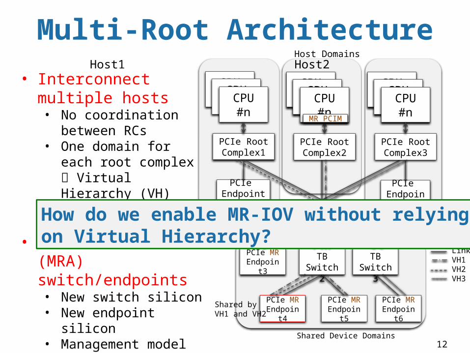
• Interconnect multiple hosts• No coordination
between RCs• One domain for each
root complex Virtual Hierarchy (VH)
• Endpoint4 is shared • Multi-Root Aware
(MRA) switch/endpoints• New switch silicon• New endpoint silicon• Management model• Lots of HW upgrades • Not/rare available
Multi-Root Architecture
CPU #n
PCIe Root Complex1
CPU #nCPU #n
PCIe MREndpoint3
PCIe MRA Switch1
PCIe TBSwitch3
PCIe TBSwitch2
PCIe MREndpoint6
PCIe MREndpoint4
PCIe MREndpoint5
PCIe Endpoint1
PCIe Endpoint2
CPU #n
PCIe Root Complex2
CPU #nCPU #n
CPU #n
PCIe Root Complex3
CPU #nCPU #n
Host Domains
Shared Device Domains
MR PCIM
LinkVH1VH2VH3
Shared by VH1 and VH2
How do we enable MR-IOV without relying on Virtual Hierarchy?
Host1 Host2 Host3
13
Non-Transparent Bridge (NTB)
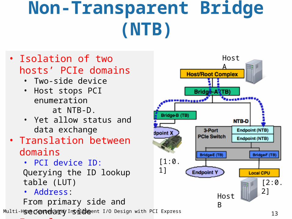
• Isolation of two hosts’ PCIe domains• Two-side device • Host stops PCI enumeration at NTB-D.• Yet allow status and data exchange
• Translation between domains• PCI device ID: Querying the ID lookup table (LUT)• Address: From primary side and secondary side
• Example: • External NTB device• CPU-integrated: Intel Xeon E5
Figure: Multi-Host System and Intelligent I/O Design with PCI Express
[1:0.1]
Host A
Host B
[2:0.2]
14
NTB Address Translation
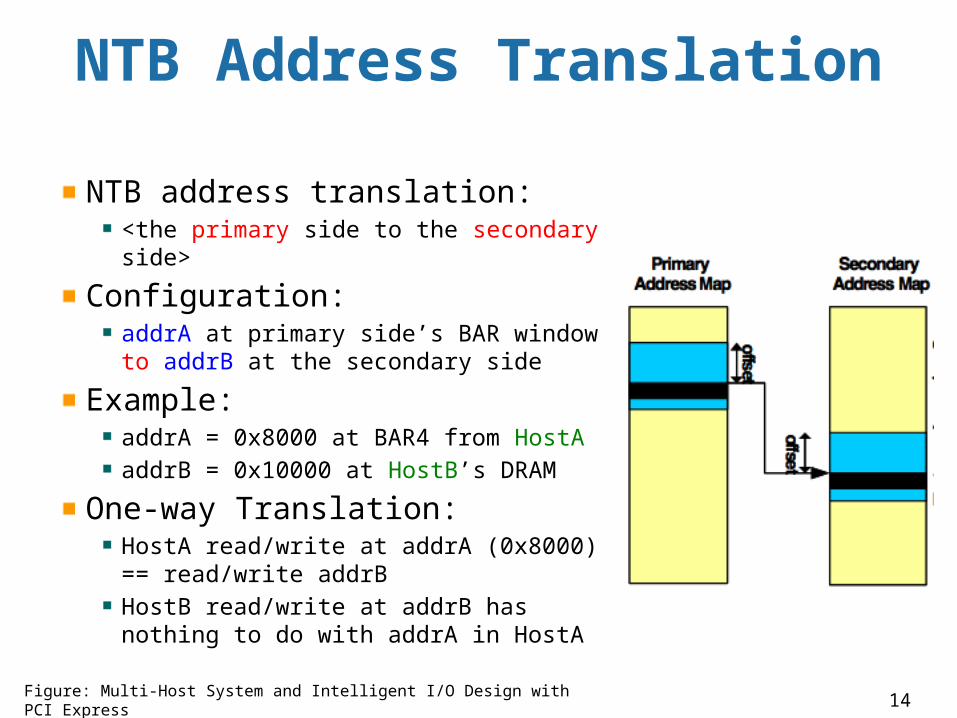
NTB address translation:<the primary side to the secondary side>
Configuration: addrA at primary side’s BAR window to addrB at the secondary side
Example:addrA = 0x8000 at BAR4 from HostA addrB = 0x10000 at HostB’s DRAM
One-way Translation:HostA read/write at addrA (0x8000) == read/write addrBHostB read/write at addrB has nothing to do with addrA in HostA
Figure: Multi-Host System and Intelligent I/O Design with PCI Express
15
I/O DEVICE SHARINGSharing SR-IOV NIC securely and efficiently [ISCA’13]
16
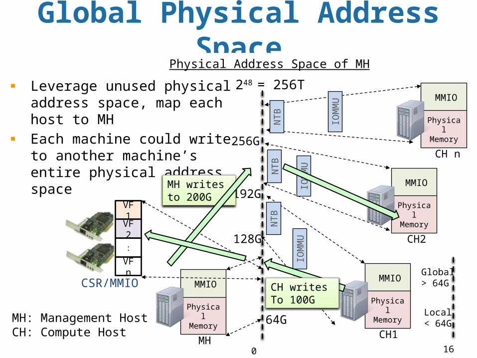
Global Physical Address Space
0
Physical Address Space of MH
248 = 256T
VF1
VF2
:
VFn MMIO
Physical Memory
CH1
MMIO
Physical Memory
MH
CSR/MMIO
MMIO
Physical Memory
CH n
MMIO
Physical Memory
CH2
NTB
NTB
IOM
MU
IOM
MU
NTB
IOM
MU
Leverage unused physical address space, map each host to MH Each machine could write to another machine’s entire physical address space
128G
192G
256G
64GLocal< 64G
Global> 64G
MH writes to 200G
CH writes To 100G
MH: Management HostCH: Compute Host
CH’s Physical Address Space
CPU
PT
NTB
IOMMU
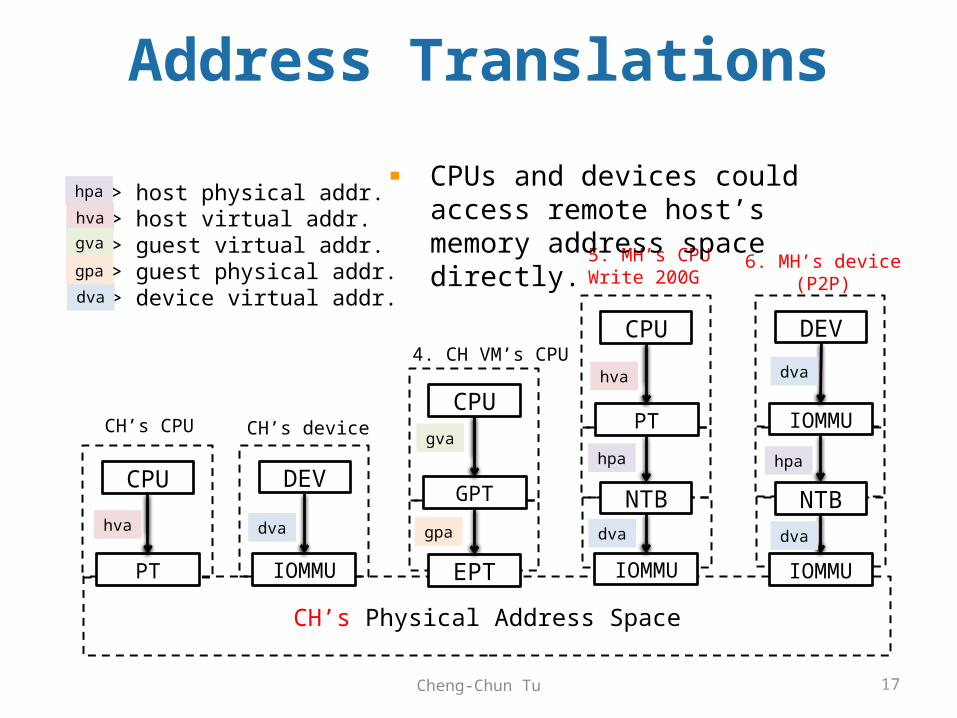
5. MH’s CPUWrite 200G
hpa
hva
dva
CPU
GPT
EPT
4. CH VM’s CPU
gva
gpa
CPU
PT
DEV
IOMMU
CH’s CPU CH’s device
dvahva
-> host physical addr.-> host virtual addr.-> guest virtual addr.-> guest physical addr.-> device virtual addr.
hpa
hva
dva
gva
gpa
NTB
IOMMU
DEV
IOMMU
6. MH’s device(P2P)
dva
dva
hpa
17Cheng-Chun Tu
Address Translations
CPUs and devices could access remote host’s memory address space directly.
18
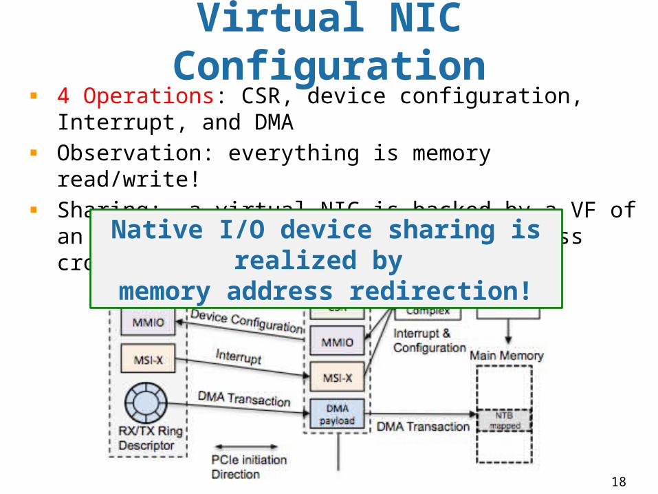
Virtual NIC Configuration4 Operations: CSR, device configuration, Interrupt, and DMAObservation: everything is memory read/write!Sharing: a virtual NIC is backed by a VF of an SRIOV NIC and redirect memory access cross PCIe domain
Native I/O device sharing is realized by
memory address redirection!
19
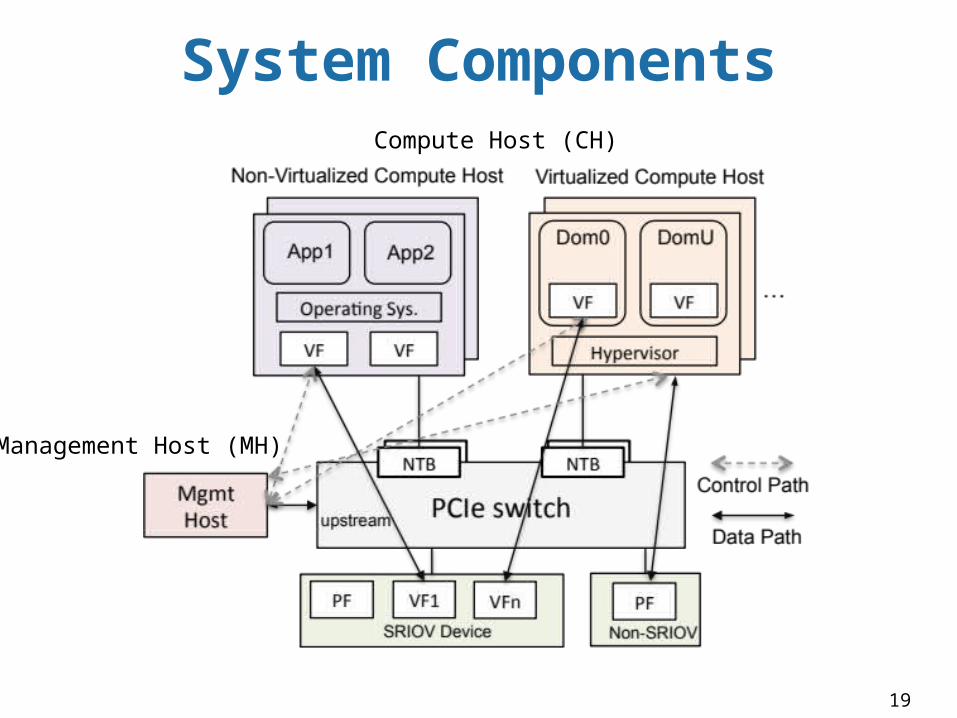
System Components
Management Host (MH)
Compute Host (CH)
20
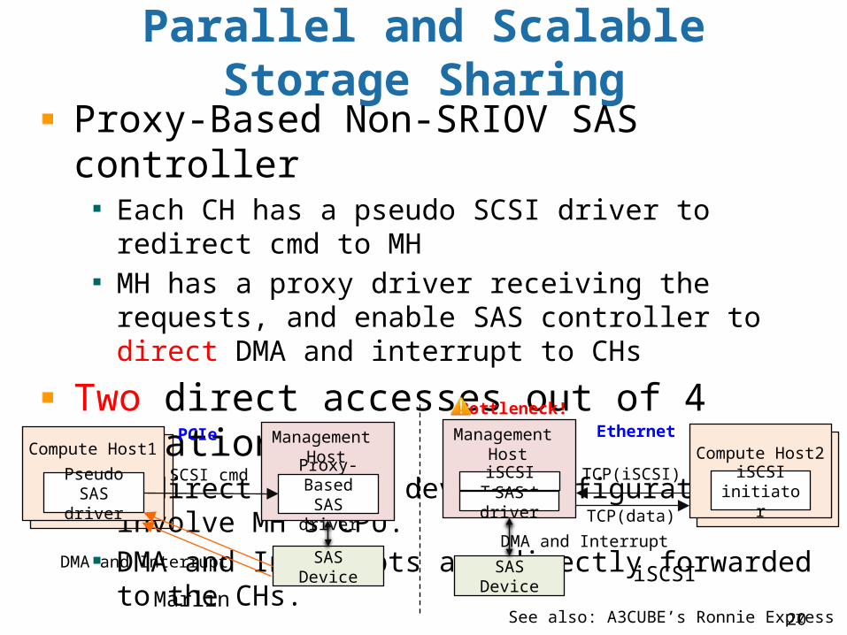
Parallel and Scalable Storage Sharing
Proxy-Based Non-SRIOV SAS controllerEach CH has a pseudo SCSI driver to redirect cmd to MH MH has a proxy driver receiving the requests, and enable SAS controller to direct DMA and interrupt to CHs
Two direct accesses out of 4 Operations:
Redirect CSR and device configuration: involve MH’s CPU.DMA and Interrupts are directly forwarded to the CHs.
Pseudo SAS driver
SAS Device
Proxy-Based SAS driver
SCSI cmd
DMA and Interrupt
Compute Host1Management
Host
iSCSI initiator
Compute Host2TCP(iSCSI)
TCP(data)
EthernetPCIe
SAS Device
iSCSI Target
Management Host
SAS driver
DMA and Interrupt
MarliniSCSI
Bottleneck!
See also: A3CUBE’s Ronnie Express
21
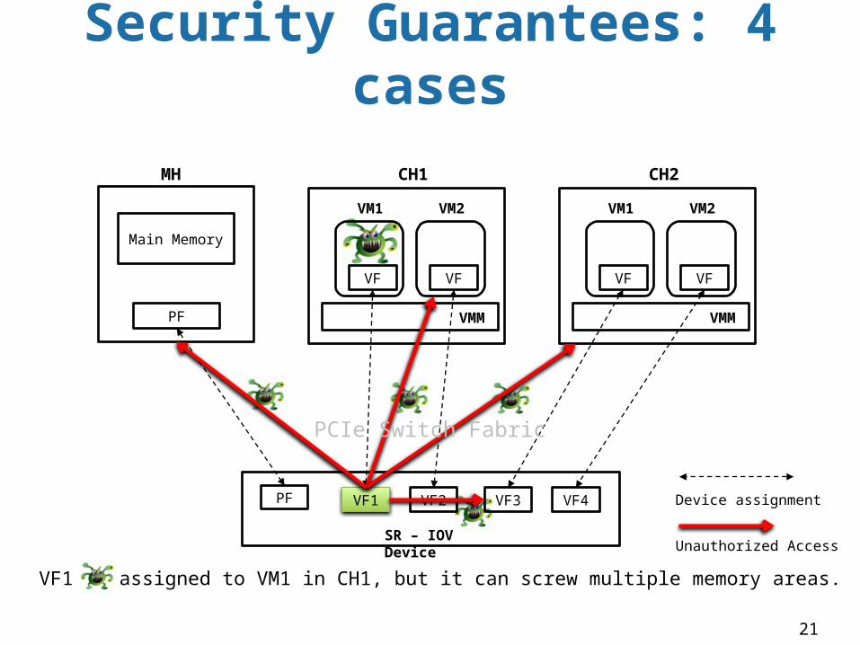
Security Guarantees: 4 cases
PF VF1
SR – IOV Device
PF
Main Memory
MH
VM1 VM2
VF VF
CH1
VMM
VM1 VM2
VF VF
CH2
VMM
VF2 VF3 VF4 Device assignment
Unauthorized Access
PCIe Switch Fabric
VF1 is assigned to VM1 in CH1, but it can screw multiple memory areas.
22
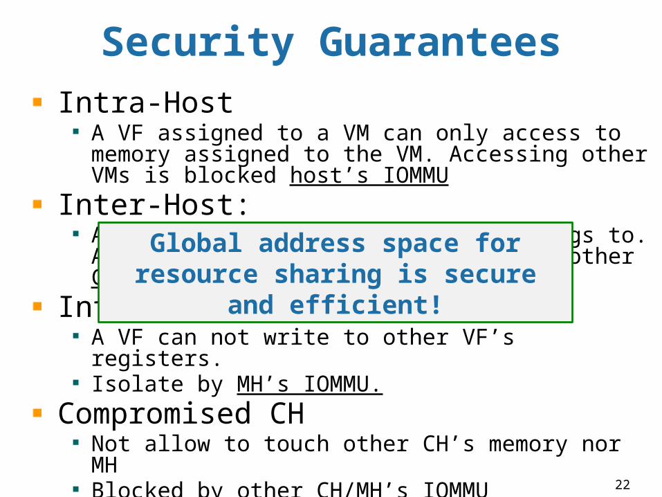
Security GuaranteesIntra-Host
A VF assigned to a VM can only access to memory assigned to the VM. Accessing other VMs is blocked host’s IOMMU
Inter-Host:A VF can only access the CH it belongs to. Accessing other hosts is blocked by other CH’s IOMMU
Inter-VF / inter-deviceA VF can not write to other VF’s registers. Isolate by MH’s IOMMU.
Compromised CHNot allow to touch other CH’s memory nor MH Blocked by other CH/MH’s IOMMU
Global address space for resource sharing is secure and
efficient!
23
INTER-HOST COMMUNICATION
Topic: Marlin Top-of-Rack Switch, Ether Over PCIe (EOP)CMMC (Cross Machine Memory Copying), High Availability
24
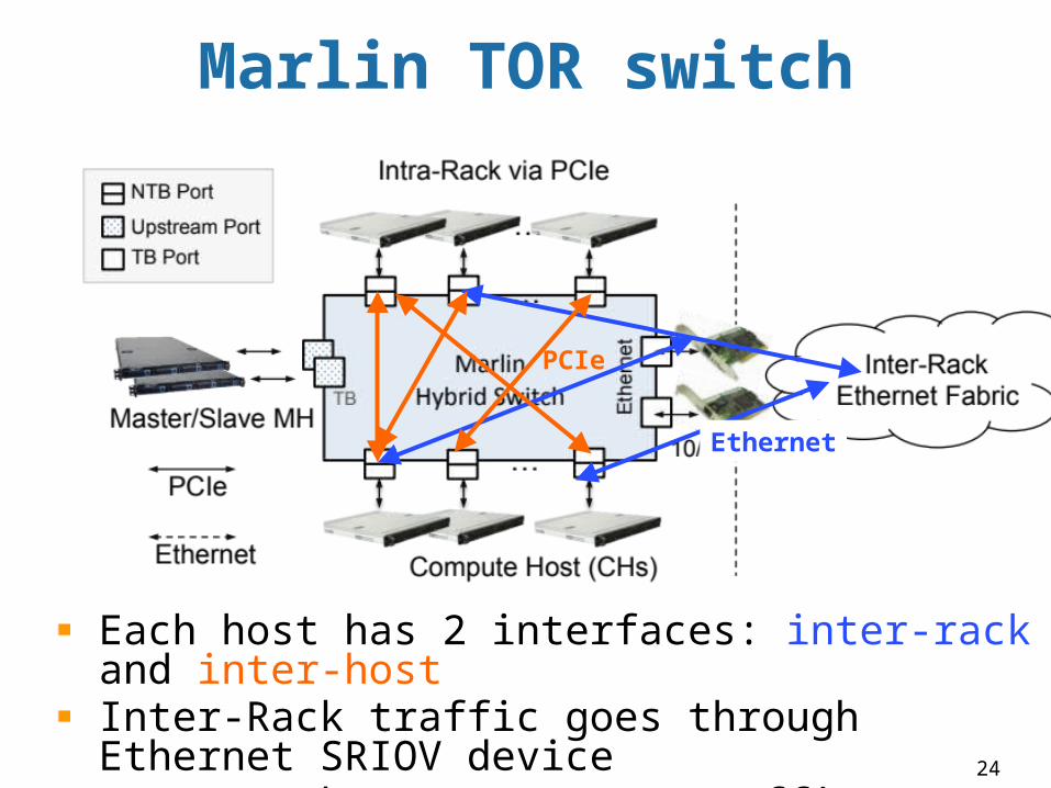
Marlin TOR switch
Each host has 2 interfaces: inter-rack and inter-host Inter-Rack traffic goes through Ethernet SRIOV deviceIntra-Rack (Inter-Host) traffic goes through PCIe
Ethernet
PCIe
25
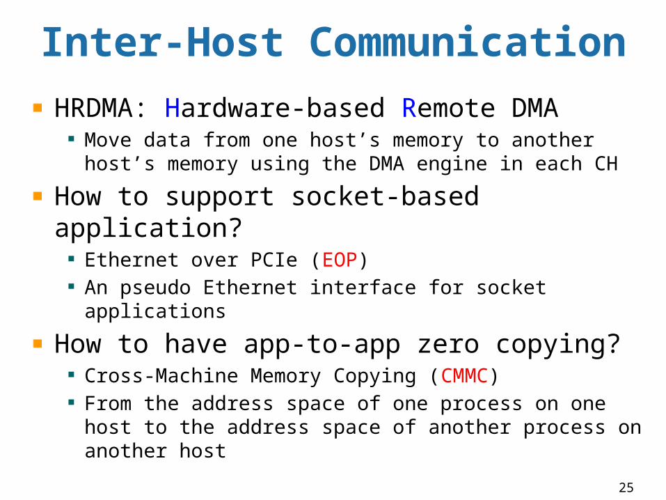
HRDMA: Hardware-based Remote DMA Move data from one host’s memory to another host’s memory using the DMA engine in each CH
How to support socket-based application? Ethernet over PCIe (EOP)An pseudo Ethernet interface for socket applications
How to have app-to-app zero copying? Cross-Machine Memory Copying (CMMC)From the address space of one process on one host to the address space of another process on another host
Inter-Host Communication
26
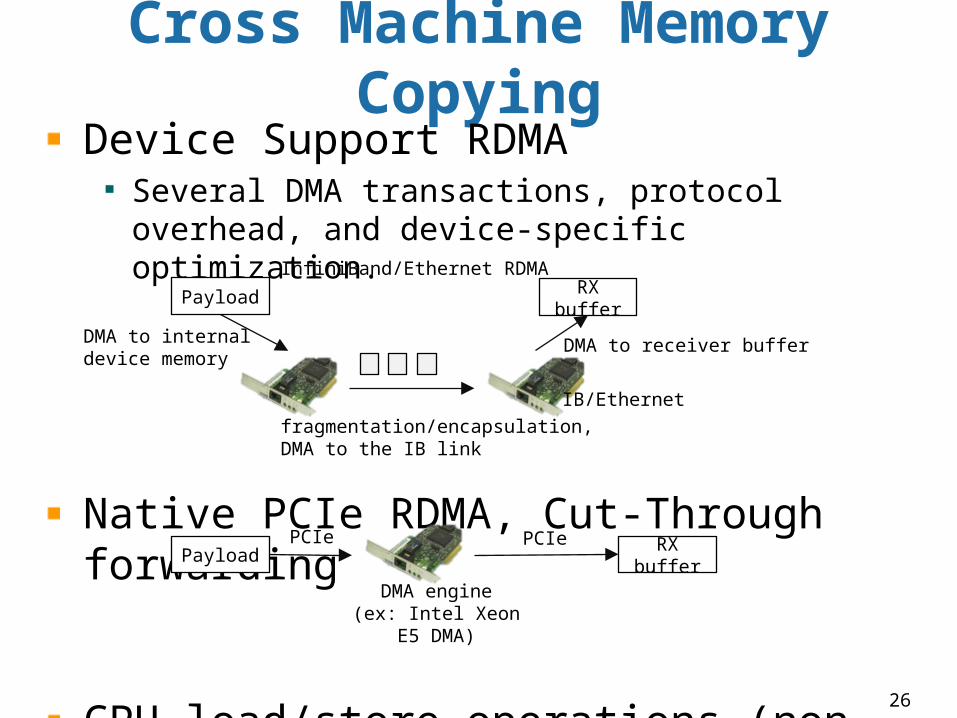
Cross Machine Memory Copying
Device Support RDMA Several DMA transactions, protocol overhead, and device-specific optimization.
Native PCIe RDMA, Cut-Through forwarding
CPU load/store operations (non-coherent)
InfiniBand/Ethernet RDMA
DMA to internal device memory
Payload
fragmentation/encapsulation,DMA to the IB link
RX buffer
DMA to receiver buffer
PCIePayload RX buffer
PCIe
DMA engine(ex: Intel Xeon E5
DMA)
IB/Ethernet
27
Inter-Host Inter-Processor INT
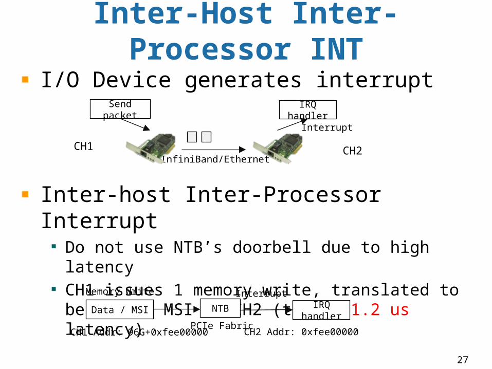
I/O Device generates interrupt
Inter-host Inter-Processor InterruptDo not use NTB’s doorbell due to high latencyCH1 issues 1 memory write, translated to become an MSI at CH2 (total: 1.2 us latency)
InfiniBand/Ethernet
Send packet IRQ handler
Interrupt
PCIe Fabric
Data / MSI IRQ handler
InterruptMemory Write
NTB
CH1 Addr: 96G+0xfee00000 CH2 Addr: 0xfee00000
CH1 CH2
28
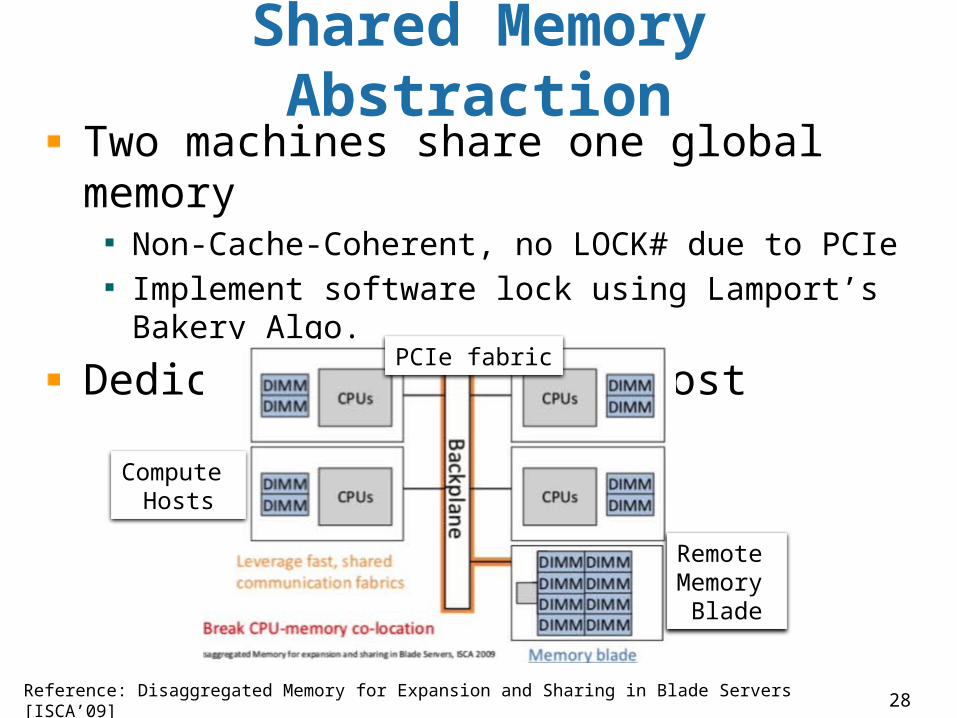
Shared Memory Abstraction
Two machines share one global memory
Non-Cache-Coherent, no LOCK# due to PCIe Implement software lock using Lamport’s Bakery Algo.
Dedicated memory to a host
Reference: Disaggregated Memory for Expansion and Sharing in Blade Servers [ISCA’09]
Remote Memory
Blade
PCIe fabric
Compute Hosts
29
Control Plane Failover
Virtual Switch 1
Ethe
rnetupstream
…
…
Slave MH
…
Master MH
VS2
Virtual Switch 2
Ethe
rnetTB
…
…
…
VS1
Slave MH
Master MH
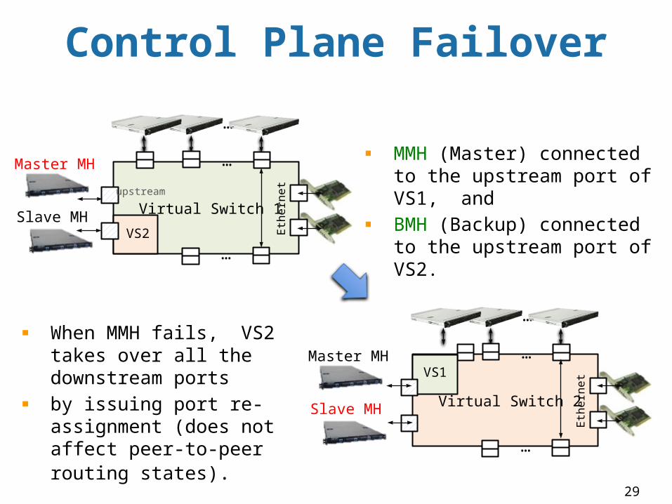
MMH (Master) connected to the upstream port of VS1, and BMH (Backup) connected to the upstream port of VS2.
When MMH fails, VS2 takes over all the downstream ports by issuing port re-assignment (does not affect peer-to-peer routing states).
30
Multi-Path Configuration
0
Physical Address Space of MH
248
MMIO
Physical Memory
MH
MMIO
Physical Memory
CH1
Prim
-NTB
Back
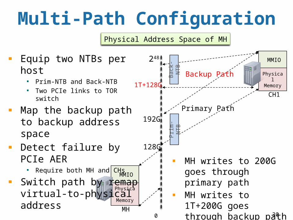
-NTBEquip two NTBs per host
Prim-NTB and Back-NTBTwo PCIe links to TOR switch
Map the backup path to backup address spaceDetect failure by PCIe AER
Require both MH and CHs
Switch path by remap virtual-to-physical address
Primary Path
Backup Path
128G
192G
1T+128G
MH writes to 200G goes through primary pathMH writes to 1T+200G goes through backup path
31
DIRECT INTERRUPT DELIVERY
Topic: Direct SRIOV Interrupt, Direct virtual device interrupt , Direct timer Interrupt
32
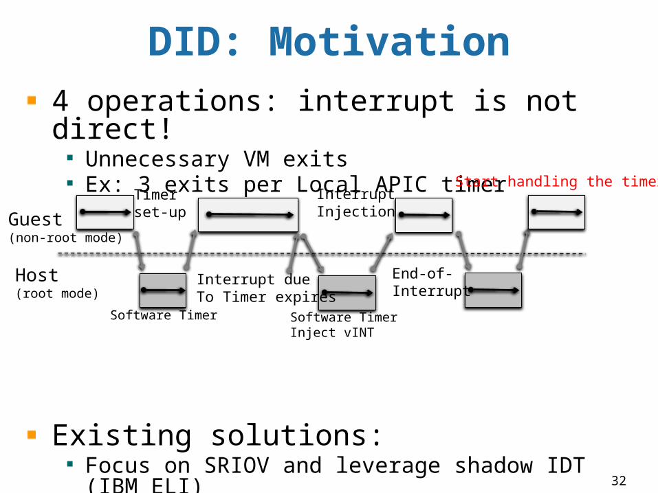
DID: Motivation4 operations: interrupt is not direct!
Unnecessary VM exitsEx: 3 exits per Local APIC timer
Existing solutions:Focus on SRIOV and leverage shadow IDT (IBM ELI)Focus on PV, require guest kernel modification (IBM ELVIS)Hardware upgrade: Intel APIC-v or AMD VGIC DID direct delivers ALL interrupts without paravirtualization
Guest(non-root mode)
Host(root mode)
Timer set-up
End-of-Interrupt
Interrupt Injection
Interrupt dueTo Timer expires
Start handling the timer
Software Timer Software Timer Inject vINT
33
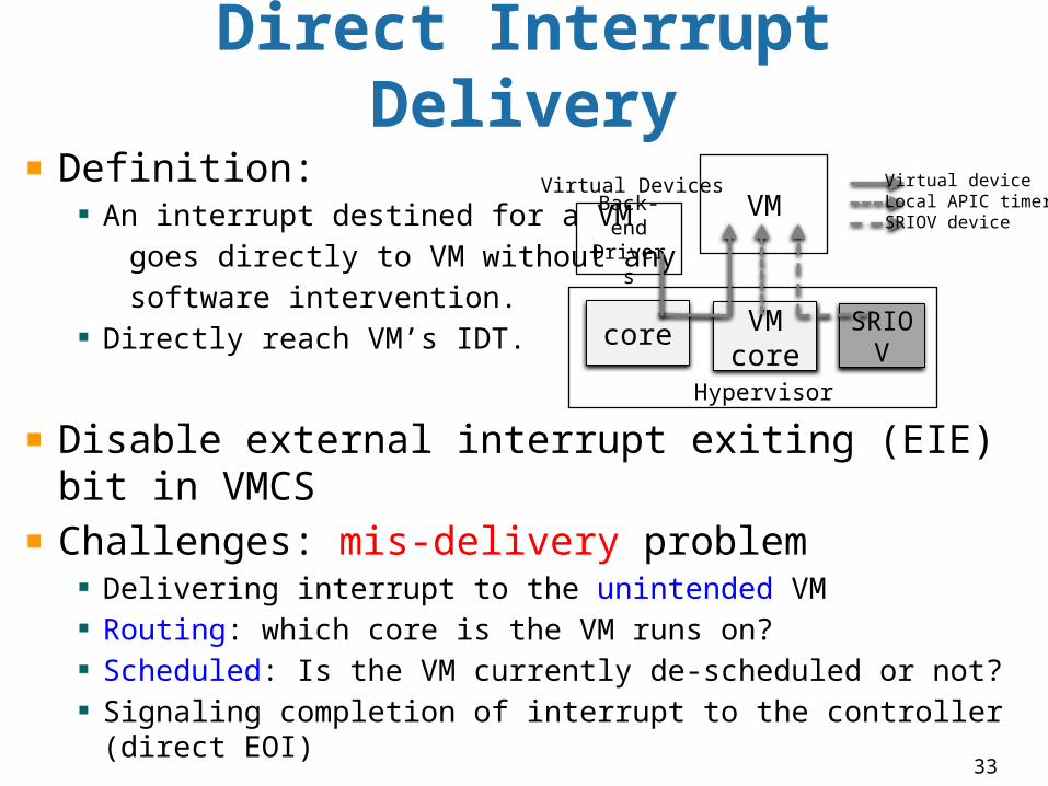
Direct Interrupt Delivery
Definition: An interrupt destined for a VM
goes directly to VM without any software intervention.
Directly reach VM’s IDT.
Disable external interrupt exiting (EIE) bit in VMCSChallenges: mis-delivery problem
Delivering interrupt to the unintended VMRouting: which core is the VM runs on?Scheduled: Is the VM currently de-scheduled or not?Signaling completion of interrupt to the controller (direct EOI)
Hypervisor
VMcore
SRIOV
Back-endDrivers
VM
core
Virtual deviceLocal APIC timerSRIOV device
Virtual Devices
34
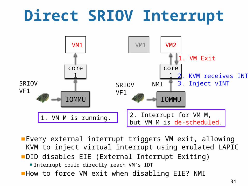
Direct SRIOV Interrupt
Every external interrupt triggers VM exit, allowing KVM to inject virtual interrupt using emulated LAPICDID disables EIE (External Interrupt Exiting)
Interrupt could directly reach VM’s IDT
How to force VM exit when disabling EIE? NMI
IOMMU
core1
VM1
IOMMU
core1
VM2
1. VM M is running. 2. Interrupt for VM M, but VM M is de-scheduled.
SRIOVVF1
NMI
1. VM Exit
2. KVM receives INT3. Inject vINTSRIOV
VF1
VM1
35
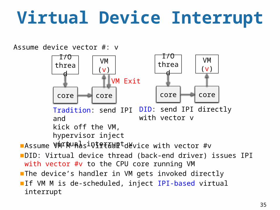
Virtual Device Interrupt
Assume VM M has virtual device with vector #vDID: Virtual device thread (back-end driver) issues IPI with vector #v to the CPU core running VMThe device’s handler in VM gets invoked directlyIf VM M is de-scheduled, inject IPI-based virtual interrupt
core
VM (v)
core
I/O thread
Tradition: send IPI and kick off the VM, hypervisor inject virtual interrupt v
core
VM (v)
core
I/O thread
DID: send IPI directly with vector v
VM Exit
Assume device vector #: v
36
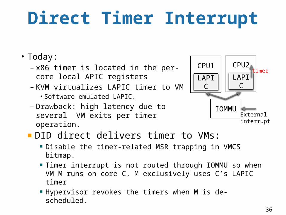
Direct Timer Interrupt
DID direct delivers timer to VMs:Disable the timer-related MSR trapping in VMCS bitmap. Timer interrupt is not routed through IOMMU so when VM M runs on core C, M exclusively uses C’s LAPIC timerHypervisor revokes the timers when M is de-scheduled.
LAPIC
IOMMU
CPU1
LAPIC
CPU2• Today:
– x86 timer is located in the per-core local APIC registers
– KVM virtualizes LAPIC timer to VM• Software-emulated LAPIC.
– Drawback: high latency due to several VM exits per timer operation.
Externalinterrupt
timer
37
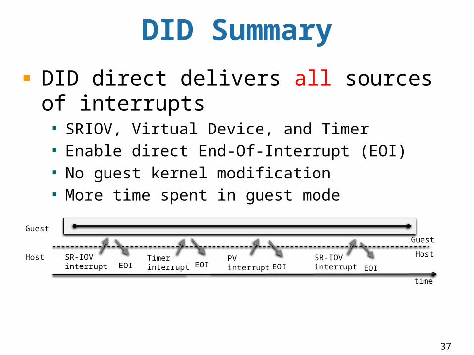
DID Summary
DID direct delivers all sources of interrupts
SRIOV, Virtual Device, and Timer Enable direct End-Of-Interrupt (EOI)No guest kernel modificationMore time spent in guest mode
SR-IOVinterrupt
Timerinterrupt
PVinterrupt
Guest
HostSR-IOVinterrupt
time
EOI EOI EOIEOI
Guest
Host
38
IMPLEMENTATION & EVALUATION
39
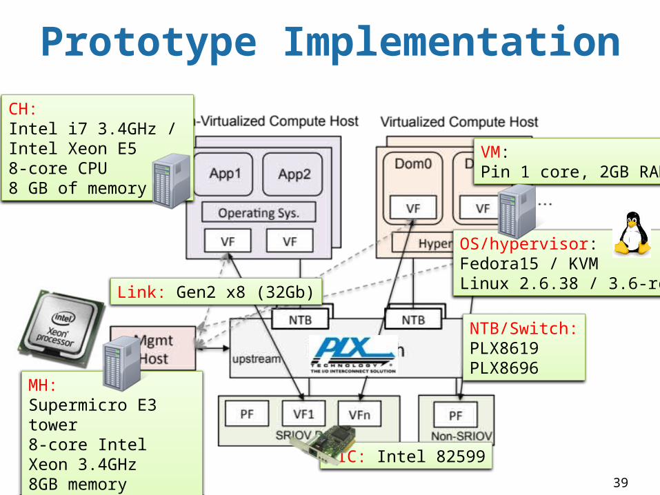
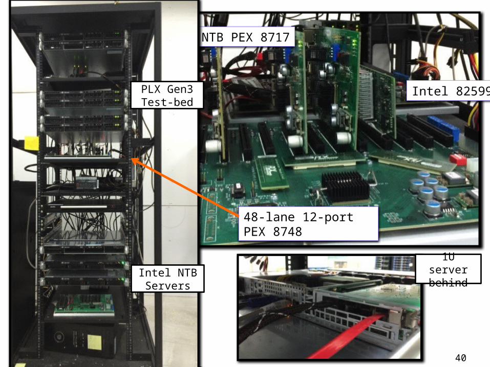
Prototype Implementation
OS/hypervisor: Fedora15 / KVM Linux 2.6.38 / 3.6-rc4
CH:Intel i7 3.4GHz / Intel Xeon E58-core CPU 8 GB of memory
MH:Supermicro E3 tower 8-core Intel Xeon 3.4GHz 8GB memory
VM:Pin 1 core, 2GB RAM
NIC: Intel 82599
Link: Gen2 x8 (32Gb)
NTB/Switch:PLX8619PLX8696
40
48-lane 12-port PEX 8748
NTB PEX 8717
Intel 82599PLX Gen3 Test-bed
Intel NTB Servers
1U server behind
41
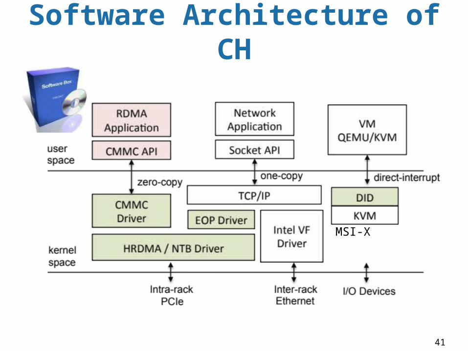
Software Architecture of CH
MSI-X
42
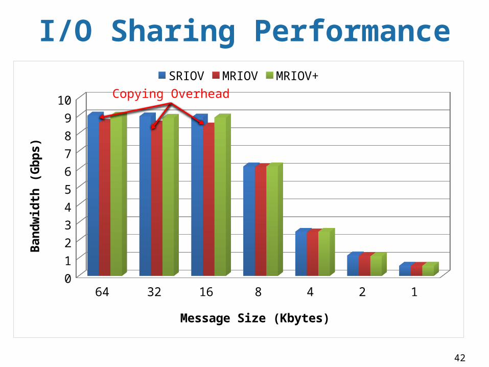
I/O Sharing Performance
64 32 16 8 4 2 10
1
2
3
4
5
6
7
8
9
10
SRIOV MRIOV MRIOV+
Message Size (Kbytes)
Band
wid
th (G
bps)
Copying Overhead
43
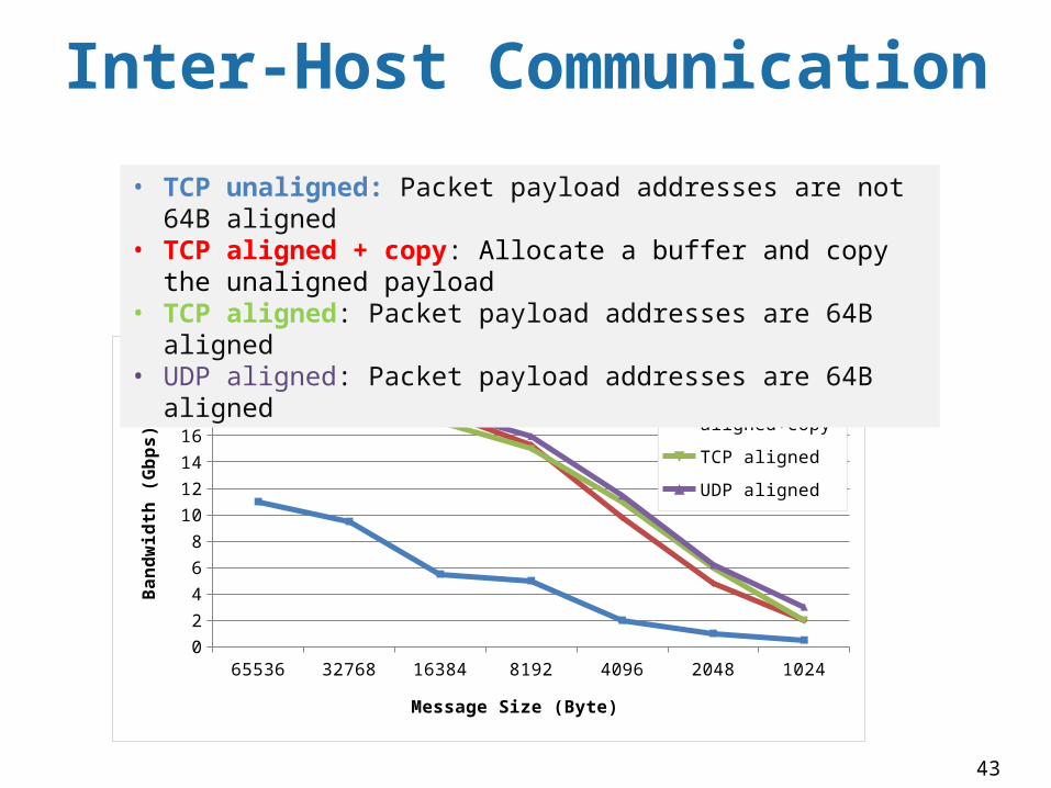
Inter-Host Communication
65536 32768 16384 8192 4096 2048 10240
2
4
6
8
10
12
14
16
18
20
22TCP unaligned
TCP aligned+copy
TCP aligned
UDP aligned
Message Size (Byte)
Band
wid
th (G
bps)
• TCP unaligned: Packet payload addresses are not 64B aligned• TCP aligned + copy: Allocate a buffer and copy the unaligned payload• TCP aligned: Packet payload addresses are 64B aligned• UDP aligned: Packet payload addresses are 64B aligned
44
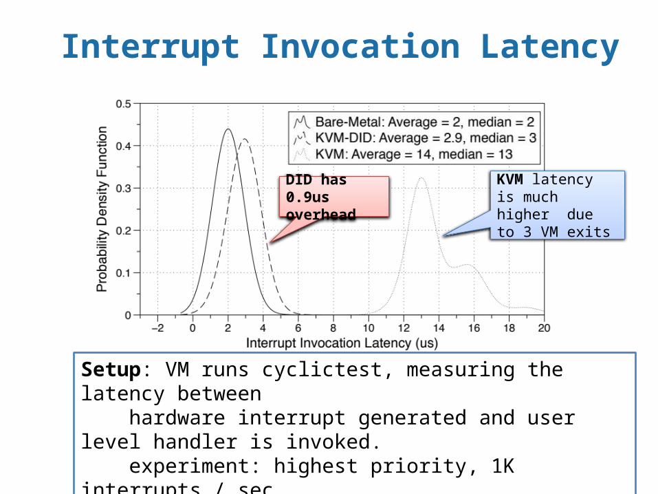
Setup: VM runs cyclictest, measuring the latency between hardware interrupt generated and user level handler is invoked. experiment: highest priority, 1K interrupts / secKVM shows 14us due to 3 exits: external interrupt, program x2APIC (TMICT), and EOI per interrupt handling.
KVM latency is much higher due to 3 VM exits
DID has 0.9us overhead
Interrupt Invocation Latency
45
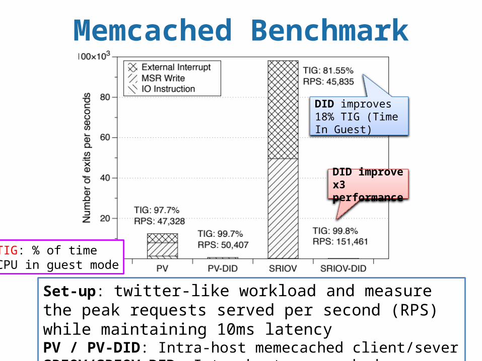
Memcached Benchmark
DID improve x3 performance
Set-up: twitter-like workload and measure the peak requests served per second (RPS) while maintaining 10ms latencyPV / PV-DID: Intra-host memecached client/severSRIOV/SRIOV-DID: Inter-host memecached client/sever
DID improves 18% TIG (Time In Guest)
TIG: % of time CPU in guest mode
46
Discussion
Ethernet / InfiniBand Designed for longer distance, larger scaleInfiniBand is limited source (only Mellanox and Intel)
QuickPath / HyperTransportCache coherent inter-processor linkShort distance, tightly integrated in a single system
NUMAlink / SCI (Scalable Coherent Interface)
High-end shared memory supercomputer
PCIe is more power-efficientTransceiver is designed for short distance connectivity
47
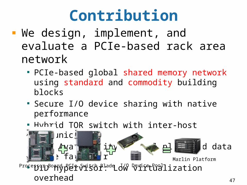
ContributionWe design, implement, and evaluate a PCIe-based rack area network
PCIe-based global shared memory network using standard and commodity building blocksSecure I/O device sharing with native performanceHybrid TOR switch with inter-host communicationHigh Availability control plane and data plane fail-overDID hypervisor: Low virtualization overhead
Marlin PlatformProcessor Board PCIe Switch Blade I/O Device Pool
48
Other Works/PublicationsSDN
Peregrine: An All-Layer-2 Container Computer Network, CLOUD’12SIMPLE-fying Middlebox Policy Enforcement Using SDN, SIGCOMM’13In-Band Control for an Ethernet-Based Software-Defined Network, SYSTOR’14
Rack Area NetworkingSecure I/O Device Sharing among Virtual Machines on Multiple Host, ISCA’13Software-Defined Memory-Based Rack Area Networking, under submission to ANCS’14A Comprehensive Implementation of Direct Interrupt,
under submission to ASPLOS’14

49
THANK YOU Question?
Dislike? Like?

![Studie „Technologische und anwendungsorientierte Potenziale …rue/PDF-Dateien/TZI-Bericht... · 2003. 6. 6. · [wearLab]@tzi TZI-Bericht Nr. 24 Studie „Technologische und anwendungsorientierte](https://img.pdfslide.net/doc/110x75/5fef5bc275df9b71697aa358/studie-atechnologische-und-anwendungsorientierte-potenziale-ruepdf-dateientzi-bericht.jpg)