Embed Size (px)
Citation preview
1
MPD 575MPD 575Design for Geometric CompatibilityDesign for Geometric Compatibility
Jonathan Weaver
Cohort 8 Jack Wildman

2
DFGC Development HistoryDFGC Development History
• This material was prepared by Cohort 8 students in the Fall of 2007:– Jack Wildman

3
Design for Geometric Compatibility Design for Geometric Compatibility
• Needs for Geometric Compatibility• Concerns with Geometric Compatibility• Customer Driven Product Direction• Digital Vehicle Definition• Product Structure• Manufacturing Structure• Plant Structure• Geometric Requirements• Reporting Results

4
Need for Geometric CompatibilityNeed for Geometric Compatibility
• Earlier verification to new customer requirements
• High Vehicle Configuration Combination complexities
• Digital Validation is Cheaper than Physical Validation
• High Cost of Tooling Rework• Ensures Proper Fit of Parts Prior to Committing
Financial Resources• Cad is the only representation of what will be
manufactured prior to prototypes

5
Need for Geometric Compatibility Need for Geometric Compatibility (Cont.)(Cont.)
• Virtual Validation can be Applied in all Aspects of System Engineering – Manufacturing Process– CAE analysis– Tooling– Stamping– Serviceability– Craftsmanship– Packaging
• Customer expectations can be Visualized Early in the System Engineering Process
• Better Design from Early No Build Conditions– More Time to Correct No Build Conditions

6
Concerns with Geometric CompatibilityConcerns with Geometric Compatibility
• Product Direction Letter (PDL) is not 100% defined early in Program
• Early Bill of Materials (BOM) is not stable• Requires discipline to manage CAD BOM
early in process • Geometric verification is not a high priority
early on• Design Contexts are work in progress early in
the vehicle development cycle• This is normal product development evolution

7
Digital Pre Assembly (DPA)Digital Pre Assembly (DPA)Ford GPDS Process (2007)Ford GPDS Process (2007)
Supplier Integration
ProductEngineering
Theme Development
Package Development
FunctionalSimulation
Product / Process Simulation
Virtual Vehicle Realization
Service
Reports
Digital Product & Process
Integration
Plant and Facilities
Digitally Aligned•Bill of Material •Bill of Process
•CAx Product Structure
Digitally Aligned•Bill of Material •Bill of Process
•CAx Product Structure
GPDS = Global Product Development SystemGPDS = Global Product Development System

8
Customer Driven Product DirectionCustomer Driven Product Direction
• Benefits of Quality Customer Direction– Shared vision by all involved activities– Proper reflection in budgets and resource plans to
execute the direction – Translation errors minimized – Order guides and broadcast (build) sheets are
accurate– Financial and supporting calculations have integrity – Parts lists and bills of material (BOM) can be
accurate • These benefits out way the concerns of
managing CAD as the actual BOM early in a program

9
Poor PDL CostsPoor PDL CostsA PDL... Cost to the Company
That does not reflect Marketing intent prevents the customer from having the intended choices.
Lost customers and lower revenue – two of the most expensive losses.
That issues confusing direction prevents coordinated responses by related activities as they each add their own interpretations.
Lost time of wasted effort and resources spent on urgent recovery.
That does not reflect Engineering capability or intent can lead to releases and builds that do not reflect intended design.
Misbuilds must be rebuilt, wrong parts may be fitted affecting performance of function and a misbuild can necessitate a recall campaign.
That does not reflect the true agreement or intent of the company and its management leads to later revisions to direction.
All the work on the earlier direction is lost and the time to prove out and optimize the later design is reduced.
That is late, or action that is decided but not properly recorded, will not be reflected in department budgets or resource plans.
The constant battle for correct resources.
That has inaccurate coding of options can lead to an inaccurate BOM.
Bills of Materials (BOM) are wrong, parts associations with uses will be wrong, engineering intent may not be reflected in BOM releases and ultimately complete misbuilds can incur (including Safety or Certification Items) causing possible recall actions.

10
• Late announcement of direction– If changes in direction are not made and announced in time to execute
the changes, the final product may be very late to market, or not have the development or prove out time desired, risking quality.
• Improper specification of Marketing features/options– One category of Program Direction Letter is the Features and Options
Summary, which specifies the arrangement of Standard and Optional features and series to be offered for a given product line. If that specification does not reflect the summary needs of both the Marketing communities and the Engineering groups that must design and develop a product.
• Unclear Program direction– When direction is announced via a PDL, the direction must be
sufficiently specific for the affected activities to take the expected actions. The level of detail of direction expands as a program progresses down the Product Development process. Later in a program, when actual parts are to be designed and prepared for production, a much more detailed work breakdown structure is required.
Poor PDL RamificationsPoor PDL Ramifications

11
Digital Vehicle Definition Digital Vehicle Definition
• Configured CAD BOM Alignment• Variants / Effectivity = Usage• 100 % 3D Geometry Defined in Context
– Product– Manufacturing– Plant
• Full Motion (Kinematics / Dynamic)• Change Management of BOM• Market Studies• Collaboration Contexts• Ford PDM
– TeamCenter Engineering (TCe)

12
• Product Development Process– Digital Verification
Vehicle Configuration Boundaries Vehicle Configuration Boundaries
Testing/Refinement
ConceptDevelopment
DetailDesign
SystemDesign
ProductionRamp up
ProductLaunch
MissionStatement
Product Planning
Ulrich and Eppinger, 1995Ulrich and Eppinger, 1995
DigitalValidation
CAD development crosses all phases

13
Configured CAD BOMConfigured CAD BOM
• Cad Product structure is aligned to the Engineering BOM– Early in the Product Development Process prior to
ordering parts these are the same BOM
• The BOM consists of Usages– A usage is all of the attributes that describes how a
part is going to be used in product– We will concentrate on Variants (Why) and Effectivity
(When) a part is valid in a BOM
• The combination of effectivity and variants is called configuration

14
Configured CAD BOM Configured CAD BOM Ford (TCe)Ford (TCe)
Options stored at Program
Level
Red Items System Breakdown
Pink Items Part Instances

15
Configured CAD BOM Configured CAD BOM Ford (TCe)Ford (TCe)
Effectivity on Part Instances
Green “V” = Variant
Condition
Quantity required for
Program

16
Configured CAD BOM (Variants) Configured CAD BOM (Variants)
• The set of variants that create a product configuration that is manufactured (buildable combination) is called a variant filter
• A variant filter is what is used to filter the product structure to different buildable combinations
• Variants/options are:– Marketing– Engineering– Procurement

17
Configured CAD BOM (Variants) Configured CAD BOM (Variants) Ford (TCe)Ford (TCe)
Variant Filter
Selected Option Values
for Product

18
Configured CAD BOM (Effectivity)Configured CAD BOM (Effectivity)
• Each revision of a part will use effectivity to track what revision is valid for a specific milestone (point in time)
• A effectivity filter is what is used to filter the product structure to see the coordinated revisions of the BOM
• When both variant and effectivity filters are applied simultaneously will be a set of parts that are going to be assembled at the plant
19
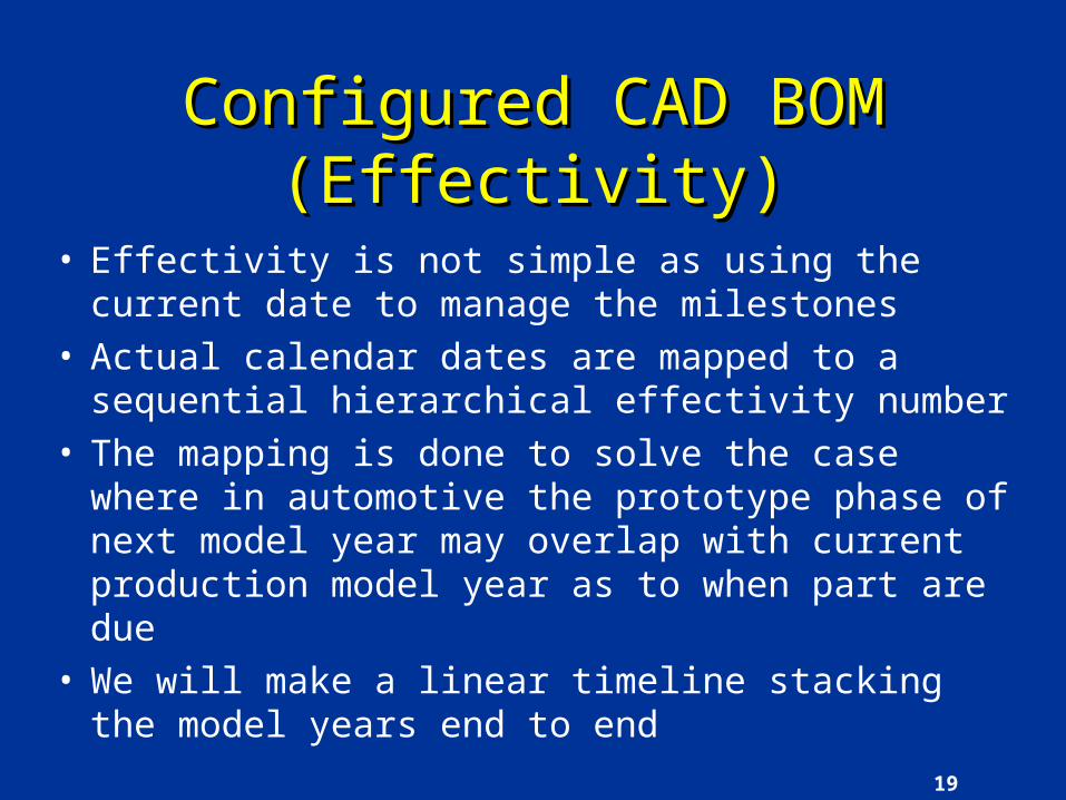
Configured CAD BOM (Effectivity)Configured CAD BOM (Effectivity)
• Effectivity is not simple as using the current date to manage the milestones
• Actual calendar dates are mapped to a sequential hierarchical effectivity number
• The mapping is done to solve the case where in automotive the prototype phase of next model year may overlap with current production model year as to when part are due
• We will make a linear timeline stacking the model years end to end

20
Each Number Increment within the Hierarchy gives Each Number Increment within the Hierarchy gives a New Block of Numbers to Manage the BOMa New Block of Numbers to Manage the BOM
1/4, 1/2, 3/4 Mod
el years
Prod
uction
/Prototyp
e P
hase
Tryou
t Bu
ild
Ph
ase
Coord
ination
P
hase
Mod
el Y
ear
1 2 3 4 567

21
Model Year Management for Perpetual TimelineModel Year Management for Perpetual Timeline
PROTO 2003 PROD
PROTO 2003.5 PROD
PROTO 2004 PROD
PROTO 2003 PROD PROTO 2003.5 PROD PROTO 2004 PROD
REALITY TIMELINES OVERLAPREALITY TIMELINES OVERLAP
TIMELINES WILL BE STACKED END TO ENDTIMELINES WILL BE STACKED END TO END
3 0 0 0 000 P
S
9 9 9 9 999 E
P
3 0 1 0 000 P
3
ONE ACTUAL TIMELINE
3 0 2 0 000 03 3 5 1 0 000 P
3.5
3 5 2 0 000 03.5
4 0 2 0 000 04
4 0 1 0 000 P
4.0
3 0 2 1 100 DB
1 3 5 2 1 100 D
B
2 4 0 2 1 100 DB
3
MILESTONES CAN BE ADDED WHERE COORDINATION IS REQUIRED
3 5 2 1 110 WA
DB
23 5 2 1 010 W
BD
B 2
3 5 9 9 999 Filter
03.5
4 9 9 9 999 Filter
O4

22
Configured CAD BOM (Effectivity)Configured CAD BOM (Effectivity)Ford (TCe)Ford (TCe)
Effectivity Rule Hierarchy
Effectivity Rule Names
(U502 Job 1 Buck)

23
100 % 3D Geometry Defined in Context100 % 3D Geometry Defined in Context
• Product Structure needs to be partitioned into Systems and Sub-Systems– Ford Uses Corporate Product System
Classification (CPSC) codes
• All Geometry Requires a Bounding Box/Space Map to Define the Spatial Location of the Part in Context
• PDM and CAD Tools will use these Spatial Relationships for Design in Context Queries

24
Configuration Rule Applied
Embedded Viewer (Design in Context)
(Clash Management)
Configured CAD BOM Configured CAD BOM Ford (TCe)Ford (TCe)

25
Full Motion (Kinematics / Dynamic)Full Motion (Kinematics / Dynamic)
• Motion of any parts simulated in the context of the vehicle program
• Motion is can be stopped in worse case conditions to design proper clearances
• Motion is used by manufacturing to see if parts can loaded
• Motion of tools and access for part attachment are also required for proper design in context

26
Vehicle Geometric Requirements Vehicle Geometric Requirements
• Requirements come from all activities– Design– Engineering– Manufacturing– Stamping
• Requirements are Part to Part, System to System or Part to System
• All requirements are derived over time

27
Vehicle Geometric RequirementsVehicle Geometric Requirements(Ford Example)(Ford Example)
System SystemCheck Value
Type of Check

28
Vehicle Geometric RequirementsVehicle Geometric Requirements(Ford Example)(Ford Example)
• Who is responsible for the interface

29
Body Engineering: Hood Sub-system
DFMEA: Hood Assy
Item/Function: Jury evaluation, Fail. Mode: Squeak & Rattle, Causal Mech: Insufficient torsional stiffness
Functional requirement: Hood Torsional Stiffness (HD-0018)
DVM: Torsional Stiffness – CAE (DVM-0027-18) Torsional Stiffness – Bench (DVM-0024-HD) Torsional Stiffness – Vehicle (DVM-0025-HD)
What
Design Rules:
Parameter: Hood Beam Depth = 25mm min
Template-based parameter set Template Part
How’sAll steel inner panel main beams (periphery) must be 25mm minimum depth for the full length of the beams
HD-010205A-0001
Ford Requirements collected in SDS, stored in SetK, assessed using DVM, compliance tracked in
eFDVS, DVP&R
Parameters collected in Excel, stored in eRoom/TMT, assessed in CAD, compliance
tracked in CAD/TMT
DR’s collected in Excel , stored in eRoom, assessed in
CAD/manually, compliance tracked in Excel
Requirements Cascade (Part)Requirements Cascade (Part)

30
Body Engineering: Hood Sub-system
DFMEA: Hood Assy
Item/Function: Jury evaluation, Fail. Mode: Squeak & Rattle, Causal Mech: Hood components rubbing
Functional requirement: Hood System Cycle Durability (HD-0018)
DVM: Hood System Key Life Durability (DVM-0033-HD)
What
Design Rules:
HowHood inner panel will maintain 20mm clearance to engine bay components
HD-010205A-0033
(ref. HD-0004)
Parameter: Hood Inner Clearance = 20 mm min
Geometric Checks: Hood outer to x > 20mmHood outer to y > 20 mm
CompliantFord Geometric checks
collected in Excel, stored in VVT, assessed in VIS/CAD compliance tracked in VVT
Requirements Cascade (Vehicle)Requirements Cascade (Vehicle)

31
Requirements Stored in TCeRequirements Stored in TCe
RequirementsStored in program context at System
level in Excel

32
Change ManagementChange Management
• The Product Lifecycle Manager (PLM)• Route Geometric Changes to Appropriate set
of Approvers for Digital Verification• Track all changes to the Product Structure
– Positional– Variant– Effectivity– Quantity– Part Number Supersedures
• Reports on health of program generated from changes tracked against usages

33
Change ManagementChange ManagementFord (TCe Workflow)Ford (TCe Workflow)
Change Manages(BOM Changes)
(Effectivity)(Sign Offs)

34
Manufacturing StructureManufacturing Structure
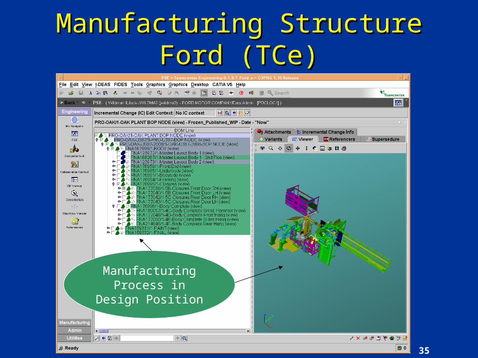
• Tooling moved to product location for combined manufacturing and product context
• This context can be launched to appropriate CAD system real time updates to fulfill geometric/functional requirements
35
Manufacturing StructureManufacturing StructureFord (TCe)Ford (TCe)
Manufacturing Process in Design
Position

36
Plant StructurePlant Structure
• Tooling and product moved to plant for production simulation
• Ergonomics studies can also be performed
• Can drive or fly through plant to see if any major space shortages are apparent

37
Plant StructurePlant StructureFord (TCe)Ford (TCe)
Plant Layout Stations moved to
Plant Context

38
ReportsReports
• The PLM system (TCe) will be used to store the product structure and design context with geometric change management authority verification sign-off
• The geometric non-compliance issues will be documented on each usage in the product structure

39
Reports Reports (cont.)(cont.)
• The report will combine all non compliant issues that cross systems that can not be solves by a single system team
• The report can be parsed by system issues or individual usage issues
• The report will be scrutinized more often as major milestones are being approached– Ford uses Global Product Development Process
(GPDS) to define the Milestones.

40
Correct Report to Correct PersonCorrect Report to Correct Person
Process
Deliverables
Metrics
Consumer Types
Validate Product
Verify Product
Create Product
Define Program
•Assumptions•PDL•BOM
•BOM•Clay•Geometry•CAE•Tools
•MFG Feasibility•DPA Compatibility•CAE validation•100% CAD/BOM•Attribute Validation
•Prototype Builds•Physical Testing
In Process Confidence True Measure of Exit Criteria
•CAD Completion•BOM Completion•Digital Evaluation
•Purpose ->
•Who can Fix Issue•Who Depend on the Data
•Functional Managers•Engineers •Supervisors•BLE
•Managers + -> VP•Program Management•Decision Makers
•Directors/VPs•Process Engineers
•Churn Metrics•Release Metrics•Build Performance•Total Cost
Process Capability/Efficiency
•BOM Verification•Digital Verification•Styling Status•PDPD Compliance
Progress to Plan How done am I
Design Done
BAD ChurnPlanned Churn
Desired PD Process

41
HeuristicsHeuristics
• Why wait till the end to find issues, verify along the design process
• Enter once and use many
• Share info early and often
• CAD is your friend
• Prototypes are very efficient in finding issues after the money has been spent

42
HeuristicsHeuristics
• Map your digital strategy and your design approach with respect to design requirements
• The percent of issues found after digital validation is proportional to the percent of errors found during physical validation
43
ReferencesReferences
• Siemens. [Online] Available http://www.plm.automation.siemens.com/en_us/products/teamcenter/solutions_by_product/index.shtml, December 5, 2007.
• Ford Motor Company. [Intranet] http://www.methods.ford.com, December 5, 2007

44
ReferencesReferences
• Patel, Naresh. “DPA Guidelines for Requirements”, 2006.
• Seippel, Steve. “Requirements Management”, 2007.