Embed Size (px)
Citation preview
1
Performance-Impact Limited
Area Fill Synthesis
Supported by Cadence Design Systems, Inc. and MARCO/DARPA GSRCSupported by Cadence Design Systems, Inc. and MARCO/DARPA GSRC
Yu Chen Yu Chen UbiTech, Inc.UbiTech, Inc.
Puneet Gupta, Andrew B. KahngPuneet Gupta, Andrew B. KahngUniv. of California, San DiegoUniv. of California, San Diego
http://vlsicad.ucsd.eduhttp://vlsicad.ucsd.edu
2
Outline
Chemical Mechanical Planarization and Area Fill
Performance-Impact Limited (PIL) Fill Problem
Capacitance and Delay Models
Approaches for PIL-Fill Problems
Computational Experiences
Conclusion and Future Works
3
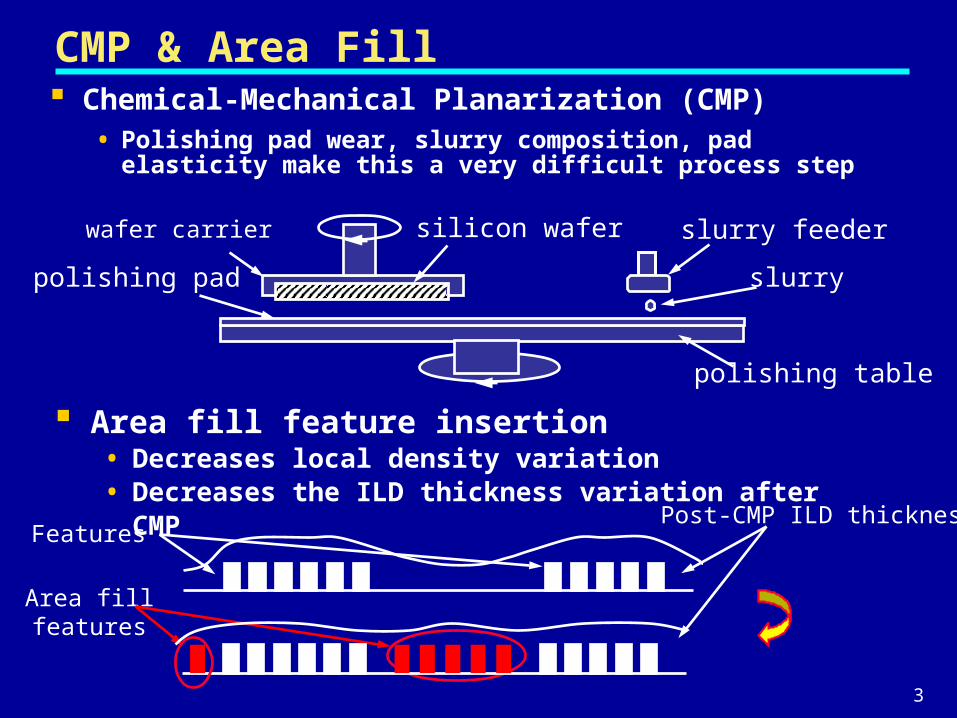
CMP & Area Fill
Area fill feature insertion• Decreases local density variation • Decreases the ILD thickness variation after CMP
Post-CMP ILD thicknessFeatures
Area fillfeatures
wafer carrier silicon wafer
polishing pad
polishing table
slurry feeder
slurry
Chemical-Mechanical Planarization (CMP)• Polishing pad wear, slurry composition, pad elasticity make
this a very difficult process step
4
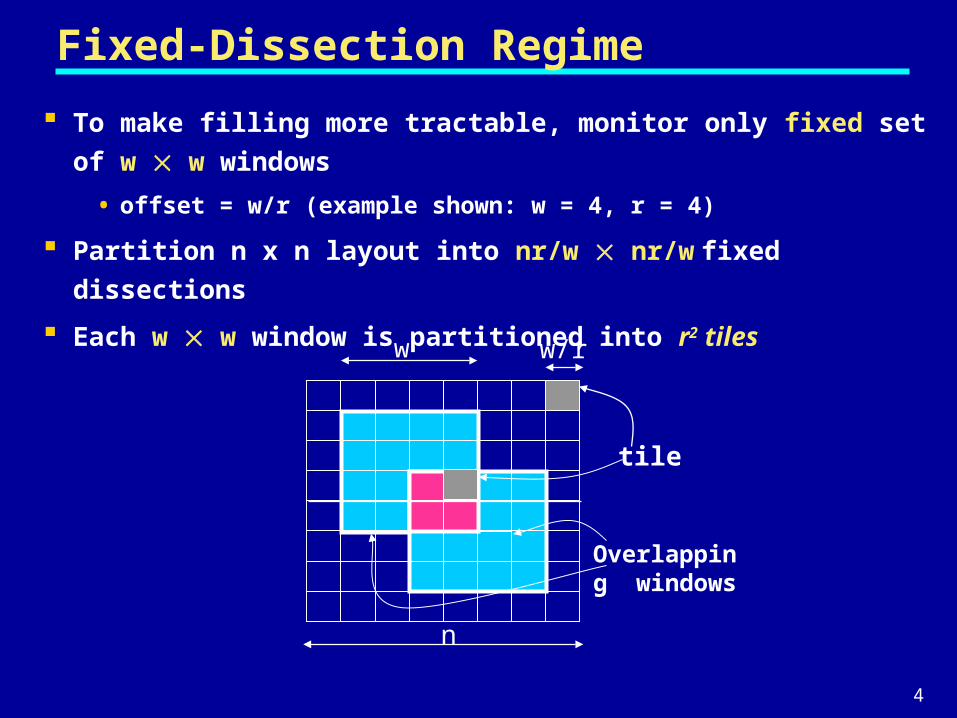
Fixed-Dissection Regime
To make filling more tractable, monitor only fixed set of w w
windows
• offset = w/r (example shown: w = 4, r = 4)
Partition n x n layout into nr/w nr/w fixed dissections
Each w w window is partitioned into r2 tiles
w/r
Overlapping windows
w
n
tile
5
Previous Objectives of Density Control
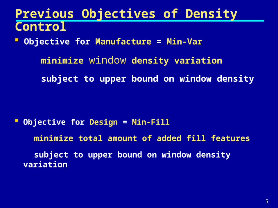
Objective for Manufacture = Min-Var
minimize window density variation
subject to upper bound on window density
Objective for Design = Min-Fill
minimize total amount of added fill features
subject to upper bound on window density variation
6
Previous Works on Area Fill
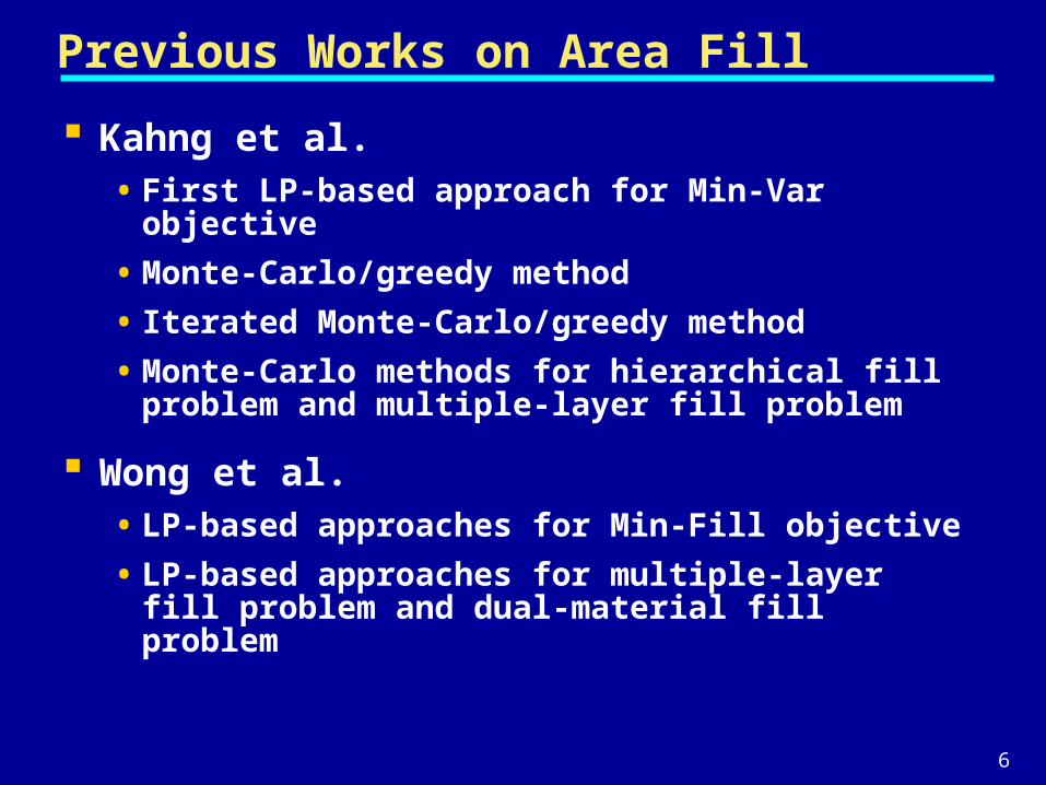
Kahng et al. • First LP-based approach for Min-Var objective
• Monte-Carlo/greedy method
• Iterated Monte-Carlo/greedy method
• Monte-Carlo methods for hierarchical fill problem and multiple-layer fill problem
Wong et al.• LP-based approaches for Min-Fill objective
• LP-based approaches for multiple-layer fill problem and dual-material fill problem
7
Outline
Chemical Mechanical Planarization and Area Fill
Performance-Impact Limited (PIL) Fill Problem
Capacitance and Delay Models
Approaches for PIL-Fill Problems
Computational Experiences
Conclusion and Future Works
8
Performance-Impact Limited Area Fill
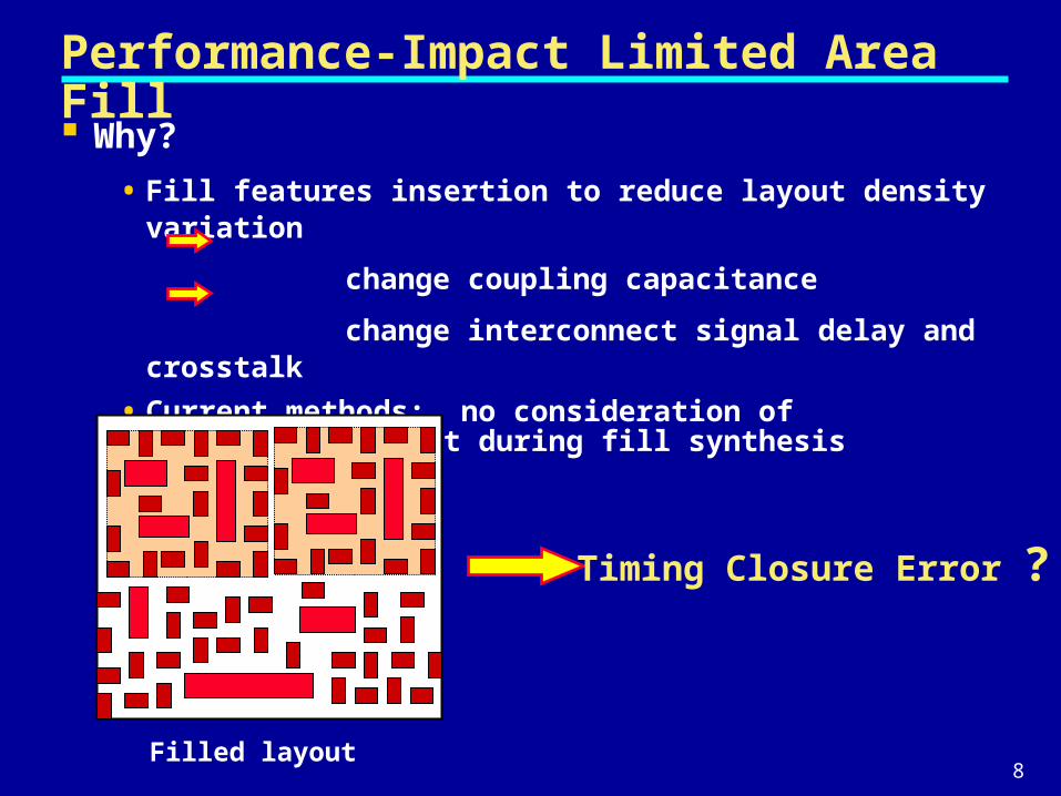
Why?
• Fill features insertion to reduce layout density variation
change coupling capacitance
change interconnect signal delay and crosstalk
• Current methods: no consideration of performance impact during fill synthesis
Filled layout
Timing Closure Error ?
9
Related Works General guidelines:
• Minimize total number of fill features
• Minimize fill feature size
• Maximize space between fill features
• Maximize buffer distance between original and fill features
Sample observations in literature• Motorola [Grobman et al., 2001]
key parameters are fill feature size and buffer distance
• Samsung [Lee et al., 2003]
floating fills must be included in chip-level RC extraction and timing analysis to avoid timing errors
• MIT MTL [Stine et al., 1998]
proposed a rule-based area fill methodology to minimize added interconnect coupling capacitance
10
Performance-Impact Limited Area Fill
Problem Formulation• Two objectives:
- minimize layout density variation due to CMP
- minimize fill features' impact on circuit performance
• In general, cannot minimize two objectives simultaneously
- minimize one objective while keeping the other as constraints
• Two formulations for PIL Fill problem
- Min-Delay-Fill-Constrained (MDFC) objective
- Max-MinSlack-Fill-Constrained (MSFC) objective
11
Min-Delay-Fill-Constrained Objective Given
• A fixed-dissection routed layout
• Design rule for floating square fill features
• Prescribed amount of fills in each tile
• Direction of current flow in each tile
• Per-unit length resistance for interconnect segment in each tile
Fill layout such that
• Performance impact (i.e., total increase in wire segment delay) is minimized
Insert fill features into each tile such that
• Total impact on delay is minimized
Weakness of MDFC objective
• can not directly consider the impact due to fill features on the signal delay of complete timing paths
12
Max-MinSlack-Fill-Constrained Objective
Given
• A fixed-dissection routed layout
• Design rule for floating square fill features
• Prescribed amount of fills in each tile
Fill layout such that
• minimum slack over all nets in the layout is maximized
13
Outline
Chemical Mechanical Planarization and Area Fill
Performance-Impact Limited (PIL) Fill Problem
Capacitance and Delay Models
Approaches for PIL-Fill Problems
Computational Experiences
Conclusion and Future Works
14
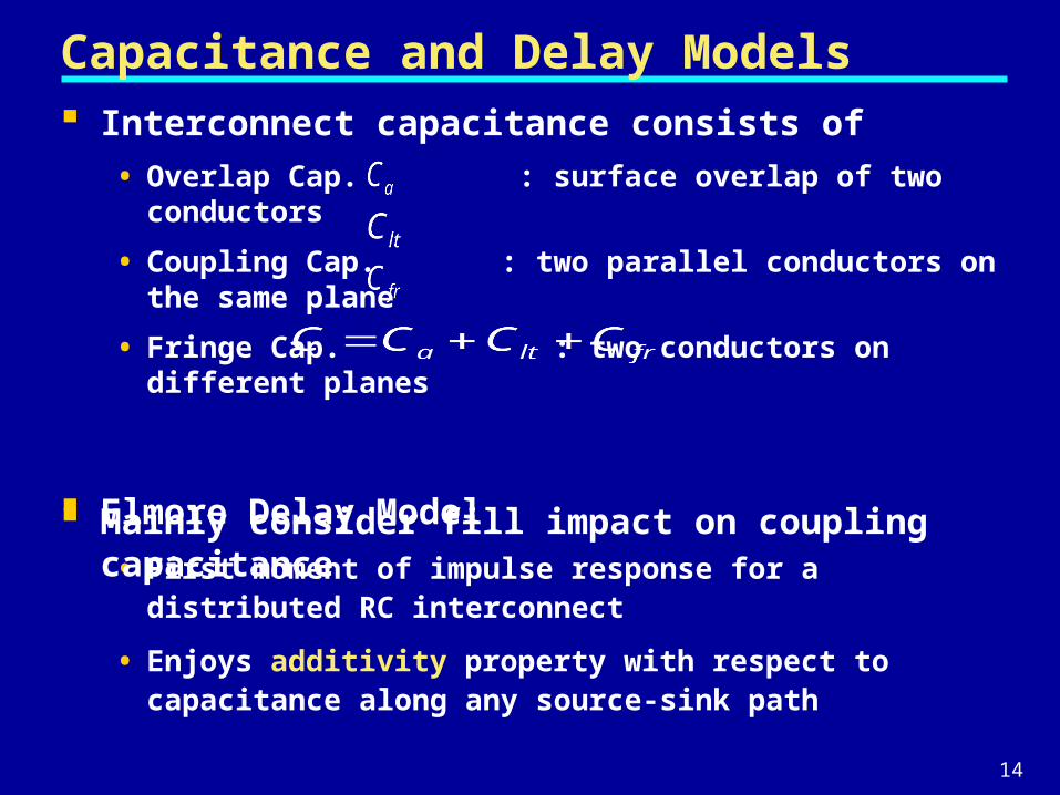
Capacitance and Delay Models
Elmore Delay Model
• First moment of impulse response for a distributed RC interconnect
• Enjoys additivity property with respect to capacitance along any source-sink path
Interconnect capacitance consists of
• Overlap Cap. : surface overlap of two conductors
• Coupling Cap. : two parallel conductors on the same plane
• Fringe Cap. : two conductors on different planes
Mainly consider fill impact on coupling capacitance
15
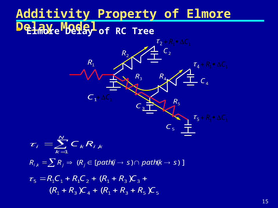
Additivity Property of Elmore Delay Model Elmore Delay of RC Tree
1C
11 CR
11 CR
11 CR
16
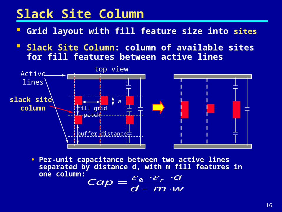
Slack Site Column Grid layout with fill feature size into sites
Slack Site Column: column of available sites for fill features between active lines
• Per-unit capacitance between two active lines separated by distance d, with m fill features in one column:
top view
buffer distance
fill gridpitch
slack site column
Activelines
w
17
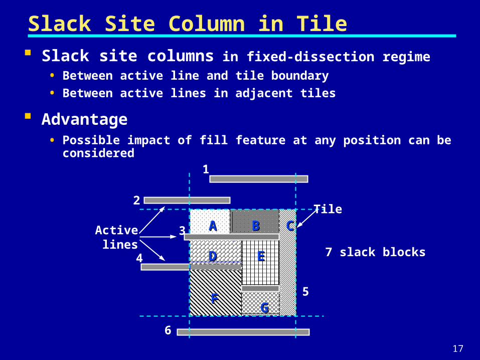
Slack Site Column in Tile Slack site columns in fixed-dissection regime
• Between active line and tile boundary
• Between active lines in adjacent tiles
Advantage• Possible impact of fill feature at any position can be considered
BBAA CC
DD EE
GGFF
1
2
3
4
6
5
Activelines
7 slack blocks
Tile
18
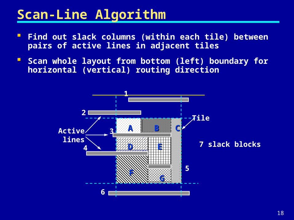
Scan-Line Algorithm
Find out slack columns (within each tile) between pairs of active lines in adjacent tiles
Scan whole layout from bottom (left) boundary for horizontal (vertical) routing direction
BBAA CC
DD EE
GGFF
1
2
3
4
6
5
Activelines
7 slack blocks
Tile
19
Outline
Chemical Mechanical Planarization and Area Fill
Performance-Impact Limited (PIL) Fill Problem
Capacitance and Delay Models
Approaches for PIL-Fill Problems
Computational Experiences
Conclusion and Future Works
20
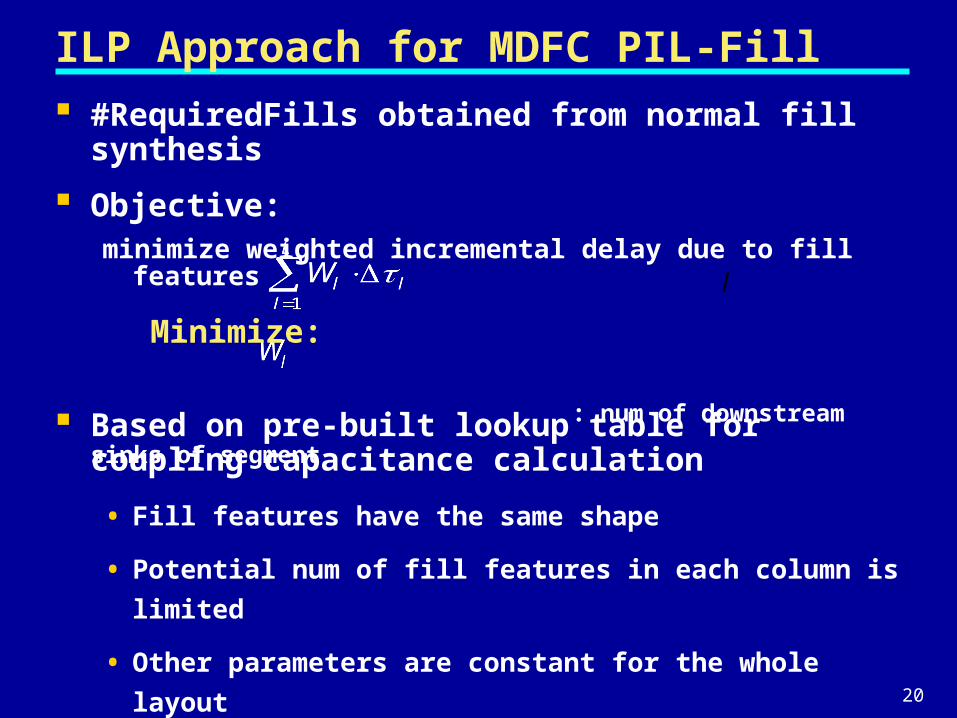
ILP Approach for MDFC PIL-Fill
l
#RequiredFills obtained from normal fill synthesis
Objective: minimize weighted incremental delay due to fill features
Minimize:
: num of downstream sinks of segment
Based on pre-built lookup table for coupling capacitance calculation
• Fill features have the same shape
• Potential num of fill features in each column is limited
• Other parameters are constant for the whole layout
21
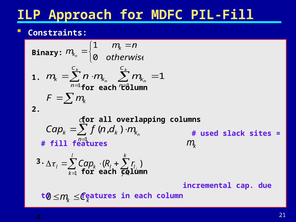
ILP Approach for MDFC PIL-Fill
kmF
l
k
k
jllkl jrRCap
1 1
)(
kk Cm 0
Constraints:
Binary:
1. for each column
2. for all overlapping columns
# used slack sites = # fill features
3. for each column
incremental cap. due to features in each column
4. for each segment
total Elmore delay increment
5. # used slack sites column size
km
11
k
n
C
nkm
k
n
C
nkkk mdnfCap
1
),(
otherwise
nmm kkn 0
1
k
n
C
nkk mnm
1
22
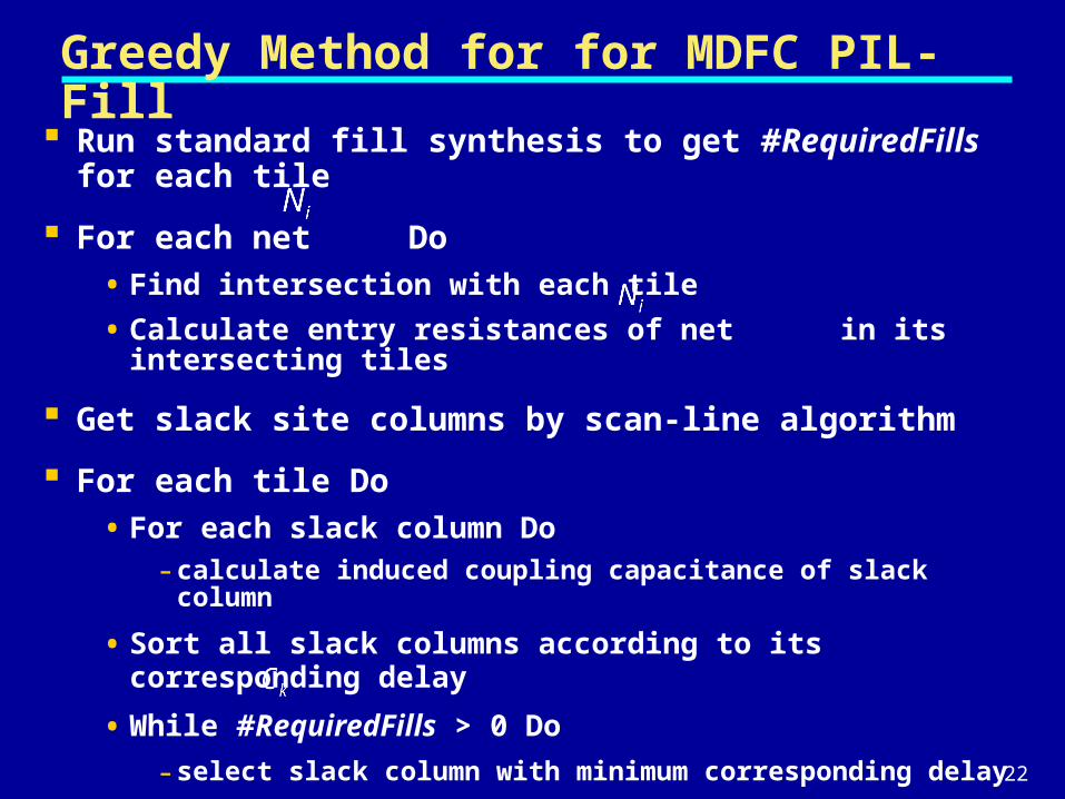
Greedy Method for for MDFC PIL-Fill
Run standard fill synthesis to get #RequiredFills for each tile
For each net Do
• Find intersection with each tile
• Calculate entry resistances of net in its intersecting tiles
Get slack site columns by scan-line algorithm
For each tile Do
• For each slack column Do- calculate induced coupling capacitance of slack column
• Sort all slack columns according to its corresponding delay
• While #RequiredFills > 0 Do
- select slack column with minimum corresponding delay
- insert features into the slack column
23
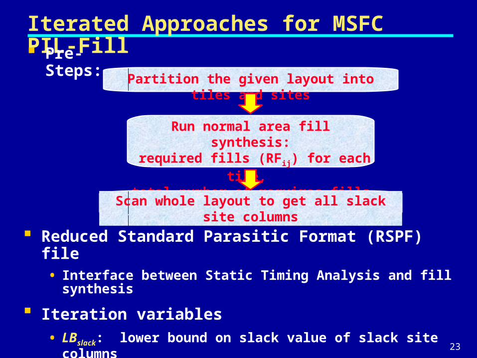
Iterated Approaches for MSFC PIL-Fill Pre-Steps:
Partition the given layout into tiles and sites
Run normal area fill synthesis: required fills (RFij) for each tile, total number of requires fills (RF)
Reduced Standard Parasitic Format (RSPF) file• Interface between Static Timing Analysis and fill synthesis
Iteration variables
• LBslack: lower bound on slack value of slack site columns
• UBdelay: upper bound on total added delay during one iteration
Scan whole layout to get all slack site columns
24
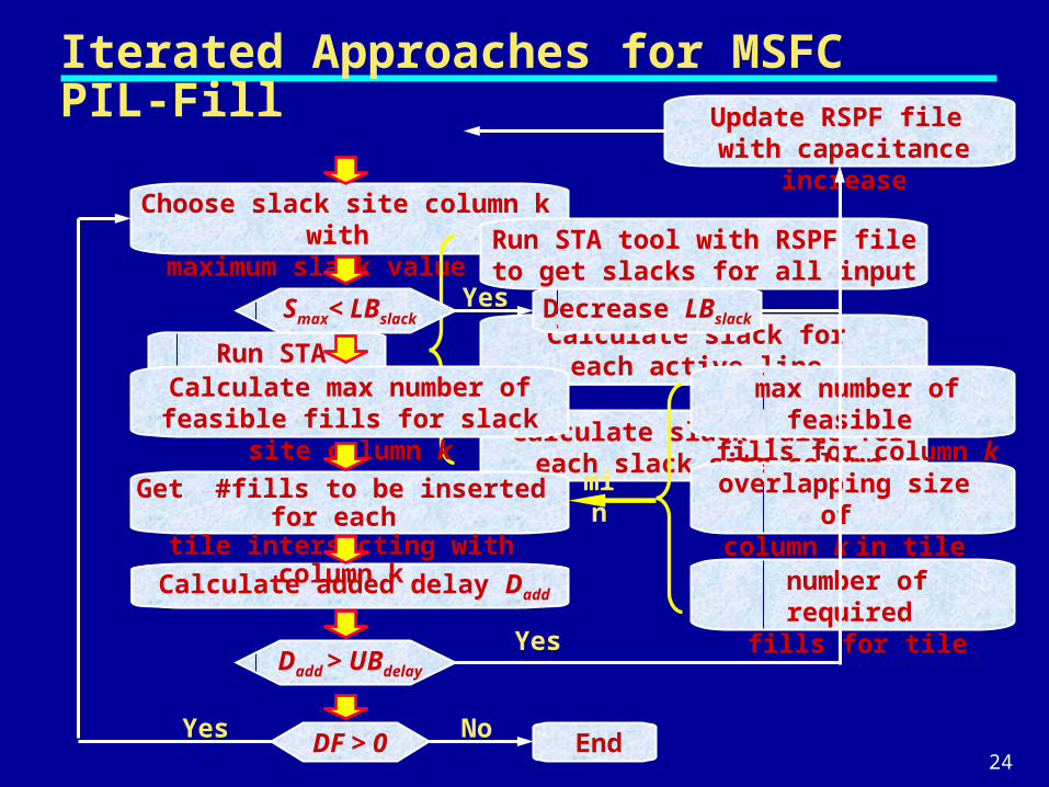
Iterated Approaches for MSFC PIL-Fill
Choose slack site column k with maximum slack value Smax
Run STA
Run STA tool with RSPF file to get slacks for all input pins
Calculate slack for each active line
Calculate slack value for each slack site column
Calculate max number of feasible fills for slack site column k
max number of feasible fills for column k
overlapping size of column k in tile
number of required fills for tile
min
Calculate added delay Dadd
Update RSPF file with capacitance increase
Get #fills to be inserted for each tile intersecting with column k
EndDF > 0NoYes
Dadd > UBdelay
Yes
Smax< LBslack Decrease LBslackYes
25
Outline
Chemical Mechanical Planarization and Area Fill
Performance-Impact Limited (PIL) Fill Problem
Capacitance and Delay Models
Approaches for PIL-Fill Problems
Computational Experiences
Conclusion and Future Works
26
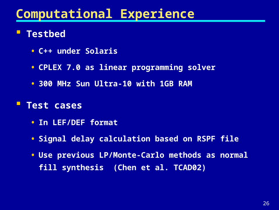
Computational Experience
Testbed
• C++ under Solaris
• CPLEX 7.0 as linear programming solver
• 300 MHz Sun Ultra-10 with 1GB RAM
Test cases
• In LEF/DEF format
• Signal delay calculation based on RSPF file
• Use previous LP/Monte-Carlo methods as normal fill
synthesis (Chen et al. TCAD02)
27
Experiments for MDFC PIL-Fill
Weighted PIL-Fill Synthesis
0
1000
2000
3000
4000
5000
6000
7000
8000
9000
1 2 3 4 5 6 7 8 9 10 11 12
T e s t c a s e s
T o
t a
l D
e l
a y
( n
s )
Normal
ILP
Greedy
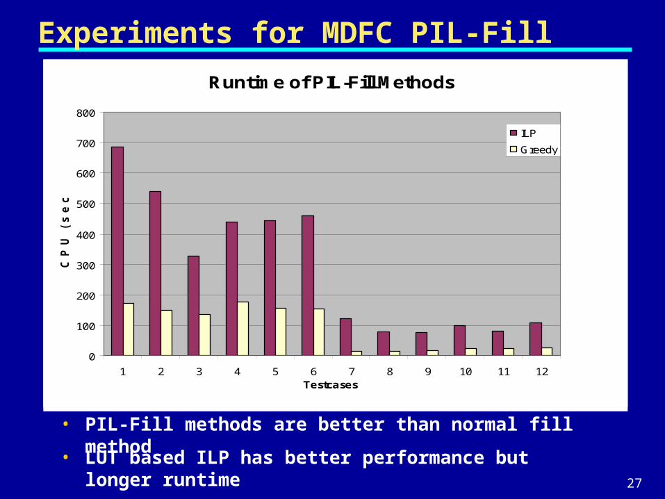
Runtime of PIL-Fill Methods
0
100
200
300
400
500
600
700
800
1 2 3 4 5 6 7 8 9 10 11 12Testcases
C P
U
( s e
c )
ILP
Greedy
• PIL-Fill methods are better than normal fill method
• LUT based ILP has better performance but longer runtime
28
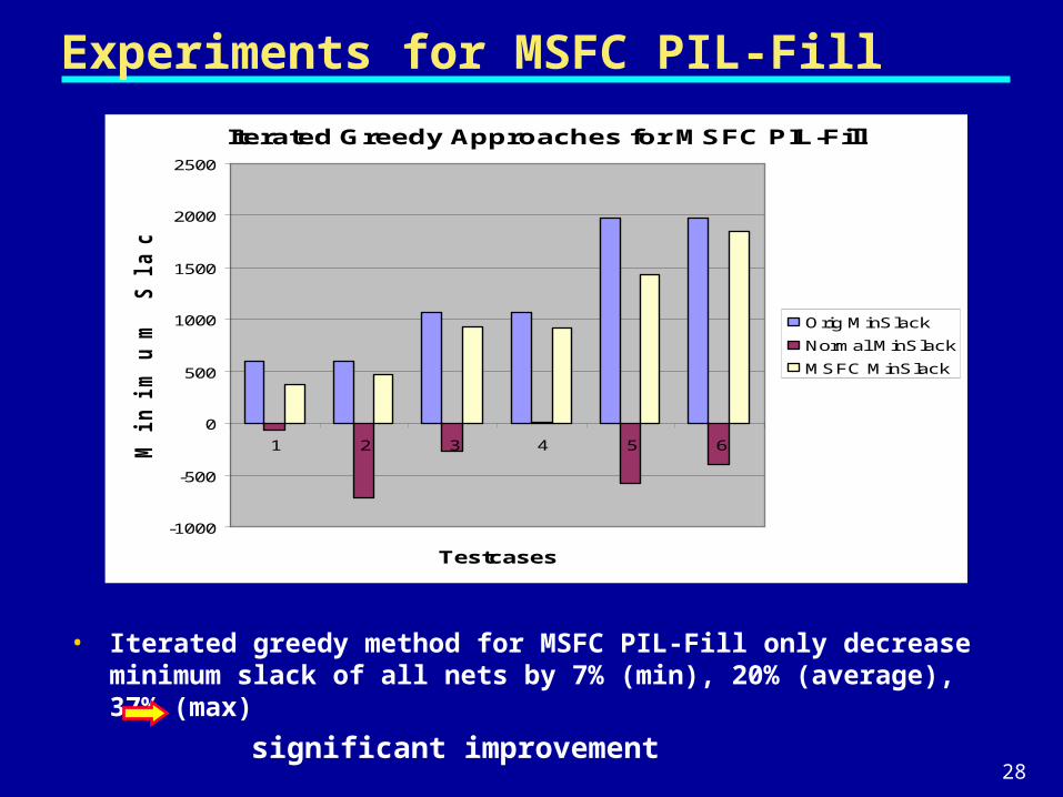
Experiments for MSFC PIL-Fill
• Iterated greedy method for MSFC PIL-Fill only decrease minimum slack of all nets by 7% (min), 20% (average), 37% (max)
significant improvement
Iterated Greedy Approaches for MSFC PIL-Fill
-1000
-500
0
500
1000
1500
2000
2500
1 2 3 4 5 6
Testcases
M i n
i m
u m
S
l a
c k
(p
s)
Orig MinSlack
Normal MinSlack
MSFC MinSlack
29
Outline
Chemical Mechanical Planarization and Area Fill
Performance-Impact Limited (PIL) Fill Problem
Capacitance and Delay Models
Approaches for PIL-Fill Problems
Computational Experiences
Conclusion and Future Works
30
Conclusions and Future Research
Contributions:
• Approximation for performance impact due to area fill insertion
• First formulations for Performance-Impact Limited Fill problem
• ILP-based and greedy-based methods for MDFC PIL-Fill problem
• Iterated greedy-based method for MSFC PIL-Fill problem
Future Works
• Budget slacks along segments avoid iteration with STA
• Consider impact due to fill on overlap and fringe capacitance
• Other PIL-Fill formulations
- Min density variation while obeying upper bound on timing
impact

31
Thank You!Thank You!


![FINAL RESULTS - Zaterdag 14 April 2018 · [13] GSRC (GBR) DNS-RD Johnstone Orla / Henderson Isla [20] GSRC (GBR) DNS-RD Milne Emily / McCann Darcy Race no. 104 JM18 2X Beker geschonken](https://img.pdfslide.net/doc/110x75/5eaca919ffaf761f9d1e9a53/final-results-zaterdag-14-april-13-gsrc-gbr-dns-rd-johnstone-orla-henderson.jpg)


![FINAL RESULTS - Zaterdag 14 April 2018€¦ · [13] GSRC (GBR) DNS-RD Johnstone Orla / Henderson Isla [20] GSRC (GBR) DNS-RD Milne Emily / McCann Darcy Race no. 104 JM18 2X Beker](https://img.pdfslide.net/doc/110x75/5eacab7a9db0d53bb67c8279/final-results-zaterdag-14-april-2018-13-gsrc-gbr-dns-rd-johnstone-orla-henderson.jpg)