Embed Size (px)
Citation preview

1
Some Ideas Behind Finite Element Analysis

2
The Engineering Approach Consider a 2-D example in linear elasticity:
A flat plate subjected to forces applied to its edge
The forces are in the plane of the plate
The plate is divided up into triangular elements

3
The Engineering Approach
Consider the element e with nodes i, j and m.

4
The Engineering Approach
The element communicates with its neighbours by forces
At node i, the force { } has two components, and
parallel to the x and y axes.
All six components of force are represented by a vector
eiF iU iV
5
The Force Vector
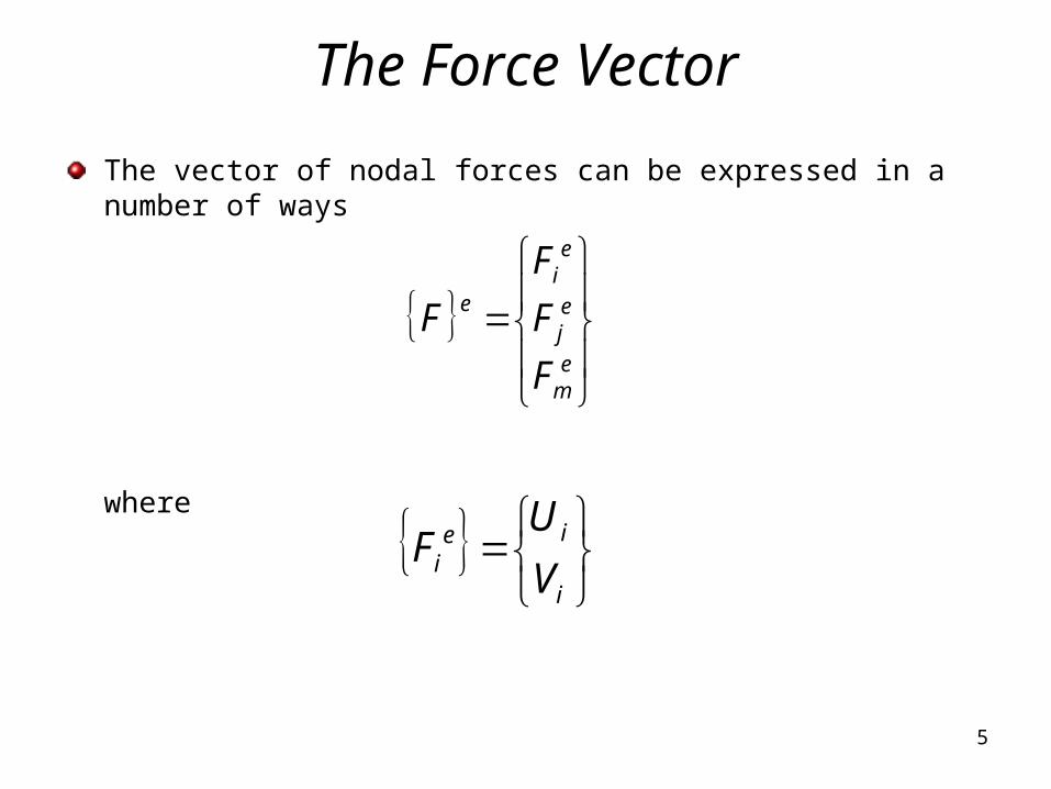
The vector of nodal forces can be expressed in a number of ways
where
em
ej
ei
e
F
F
F
F
i
iei V
UF

6
The Force Vector
The force vector for the complete element is written as,
m
m
j
j
i
i
e
V
U
V
U
V
U
F

7
The Displacement Vector
Each node has two displacement components, u and v (2D
analysis)
The displacement of node i parallel to the x-axis is denoted by
and that parallel to the y-axis by
The vector of nodal displacements, is
where
m
j
ie
i
ii v
u
iU
iV
e

8
The Displacement Vector
The complete displacement vector is
m
m
j
j
i
i
e
v
u
v
u
v
u

9
The Displacement Vector
If the nodes are displaced by the same vector, the element is
translated without strain
This is known as rigid body displacement
If the nodes rotate by the same amount, the element rotates without
strain
This is known as a rigid body rotation
The nodal forces are zero for a rigid translation or rotation
The mechanical properties of the material are needed to make the
link between nodal displacements and nodal forces
10
The stiffness matrix
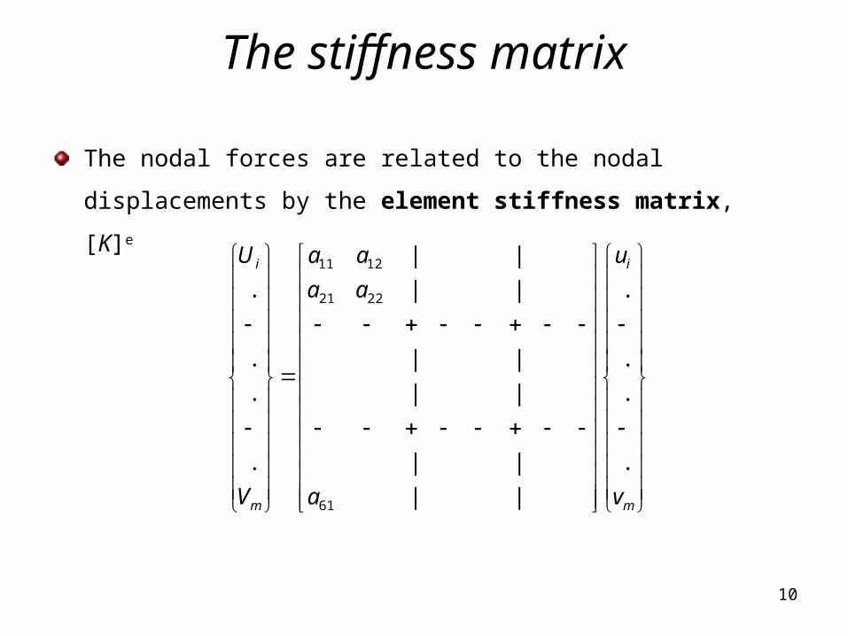
The nodal forces are related to the nodal displacements by the
element stiffness matrix, [K]e
m
i
m
i
v
u
a
aa
aa
V
U
.
.
.
.
||
||
||
||
||
||
.
.
.
.
61
2221
1211

11
The Finite Element Equation
The 6x6 element stiffness matrix is patitioned into nine 2x2
submatrices, so that
where the partitions of the stiffness matrix is,
m
j
i
emm
emj
emi
ejm
ejj
eji
eim
eij
eii
e
em
ej
ei
kkk
kkk
kkk
F
F
F
2221
1211
aa
aak eii

12
The Finite Element Process
Once the element stiffness matrices are calculated then they are
assembled into a global stiffness matrix for the entire model
The externally applied force {F1} produces nodal forces {Fl}, {Fm} and
{Fn} acting on the elements l, m and n

13
The Finite Element Process
For a simple mesh consisting of three elements the global stiffness
matrix is found as follows
14
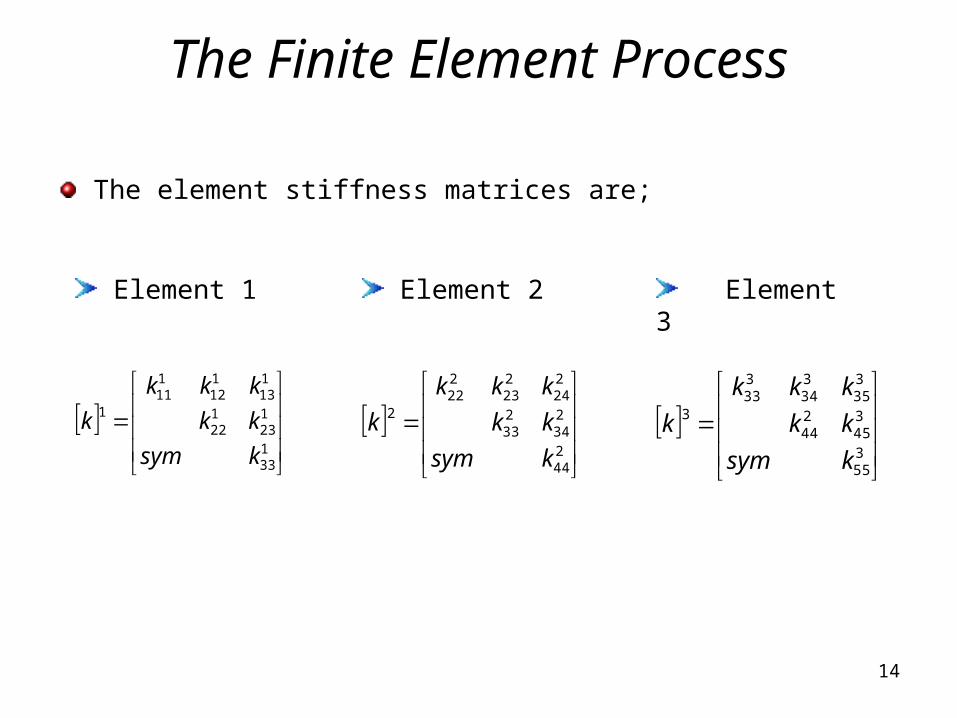
The Finite Element Process
The element stiffness matrices are;
133
123
122
113
112
111
1
ksym
kk
kkk
k
Element 1 Element 2 Element 3
244
234
233
224
223
222
2
ksym
kk
kkk
k
355
345
244
335
334
333
3
ksym
kk
kkk
k

15
The Finite Element Process
The global stiffness matrix, K, is assembled using the principle of
superposition:
355
354
353
345
344
244
343
243
242
335
234
232
333
233
133
232
132
131
224
223
123
222
122
121
113
112
111
00
0
0
00
kkk
kkkkkk
kkkkkkkkk
kkkkkk
kkk
K

16
The Finite Element Process
In this way, if the vector of external forces applied to the various
nodes is [F1 F2 F3 F4 F5 ]T ,then
5
4
3
2
1
35
34
24
33
23
13
21
11
11
5
4
3
2
1
K
F
FF
FFF
FF
F
F
F
F
F
F
17
The Finite Element Process
It is possible to solve for the nodal forces given a complete set of
nodal displacements
The more common problem is to solve for the nodal displacements
given a set of externally applied forces

18
The Finite Element Process
The stiffness matrix has a strong leading diagonal
The matrix is square, symmetric and is positive definite
At this point, the assembled stiffness matrix is singular
No solution can be obtained
Physically the model is not fixed in space
All rigid body motions must be restrained before a solution is
possible

19
The Finite Element Process
Adequate restraints have to be inserted
Only one set of nodal displacements is possible for any set of
imposed nodal forces.
The nodal displacements are found by solving a set of simultaneous
equations
From the displacements the strains are calculated
From the strains the corresponding stresses are found

20
The Principles of Virtual Displacement
Consider a particle acted on by a number of forces,
A virtual displacement of the particle is imagined to be so small that the
forces applied to the particle remain unchanged in magnitude and
direction.

21
The Principles of Virtual Displacement
In equilibrium the resultant force acting on the particle is zero
The work done by a force is equal to the work done by its
components
Forces acting on particle are considered part of net force
The net force is zero (for equilibrium)
The virtual work done by the virtual displacement is zero

22
The Principles of Virtual Displacement
Consider an elastic body represented by a system of two
particles joined by an elastic spring
A possible virtual displacement is indicated by the vector ds
involving displacement of the particle 2.

23
The Principles of Virtual Displacement
The force exerted by the spring is equal to the spring constant, k,
multiplied by the extension of the spring , Δ
Applying the principle of virtual work
0... 21 sksFsF

24
The Principles of Virtual Displacement
The individual contributions have been given in terms of the
appropriate scalar product
(kΔ).δs represents the change in the stored energy in the spring
The change in the elastic stored energy caused by the virtual
displacement has to be taken into account
0... 21 sksFsF

25
The Principles of Virtual Displacement
Consider an elastic solid in equilibrium before and after the
imposition of a virtual displacement to a system of forces applied to
it.

26
The Principles of Virtual Displacement
The virtual displacement gives rise to virtual strains
The virtual strains are compatible with the virtual displacements of
the forces acting on the solid
The stresses remain unchanged by the virtual displacement
The change in strain energy per unit volume caused by the virtual
displacement is}{ { } .{ }T

27
The Principles of Virtual Displacement
The total change in the stored strain energy in the body is
If there are n external forces, each with components in the
reference x, y, and z direction, such as
and each undergoes its own virtual displacement
Vol
T dVolU
Tziyixii PPPP ,,,
Tziyixii ssss ,,,

28
The Principles of Virtual Displacement
The work done by the external forces equals the increase in the
stored energy, by the Principle of Virtual Work,
The left-hand side of this equation can be replaced by an integral
over an area in the case of distributed loads
The Principle of Virtual Displacements is used to find nodal forces
in formulated element stiffness matrices
dVoldsPn
i Vol
Ti
Ti
1

29
The Theory of Minimum Total Potential Energy
It was found using the Principle of Virtual Work that
The left-hand side of this equation is the work done by the external forces
as a result of the set of virtual displacements
This is the loss in the potential energy of the system of external forces
The right-hand side is the increase in the strain energy of the elastic body
dVoldsPn
i Vol
Ti
Ti
1

30
The Theory of Minimum Total Potential Energy
If, is the potential energy of the system, then
In the equilibrium condition the potential energy of the system has
an extreme value of a maximum or a minimum.
01
dVolspdTn
i Vol
iT
i

31
Shape Function
The displacement of any point within an element is a function of the
nodal displacements and of the position of the point. This is
expressed by means of shape functions.

32
Shape Function
For any point P with coordinates (x, y) the displacement can be
expressed as
where
and
Each shape function is a function of position, Ni=Ni (x,y)
uNuNuNuNu Tmmjjii
mjiT NNNN
mjiT uuuu

33
Conditions the shape functions must fulfil
At node i, the displacement is given in terms of the nodal
displacements
For this to be true for any value of nodal displacement, it can be
seen that Ni must equal 1 and the shape functions at all other
nodes zero. The same is true for all the other shape functions, i.e.
mmjjiii uNuNuNu
pq
pqforyxN qqp
0
1

34
Conditions the shape functions must fulfil
The displacement must be continuous between elements
The shape function of a node is zero along a boundary not
containing that node.
The shape functions should be able to represent rigid translation,
i.e.
This condition requires that Ni + Nj + Nm=1 for all points in the
element
mji
mjimmjjii NNNNNN
35
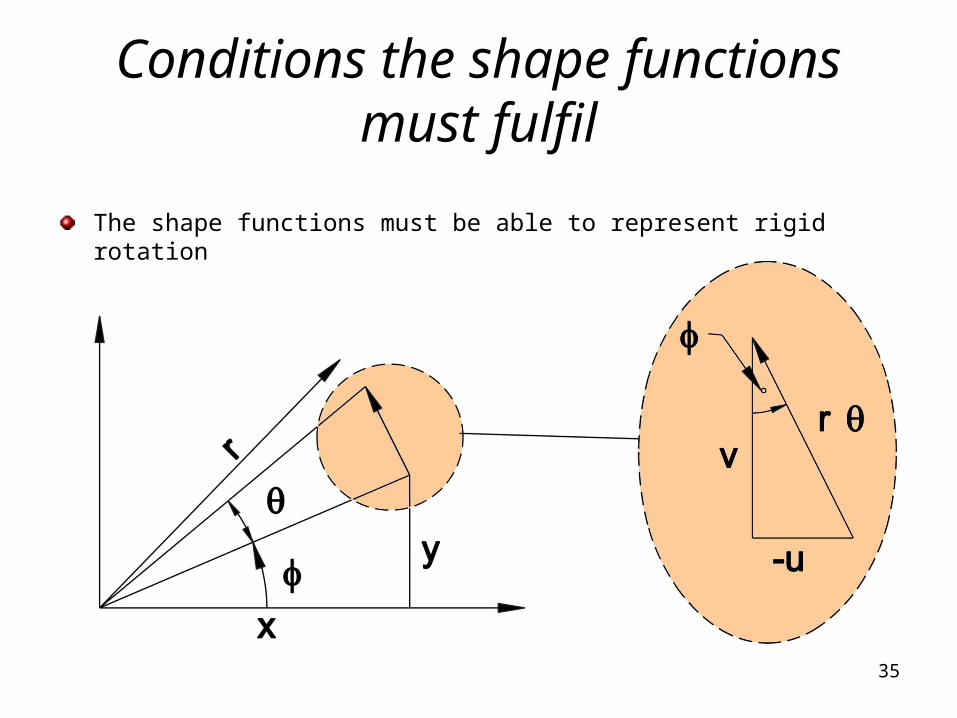
Conditions the shape functions must fulfil
The shape functions must be able to represent rigid rotation

36
Conditions the shape functions must fulfil
A point P, with coordinates (x, y) is subjected to a small rotation
about the origin, causing it to move through a distance rө. The
component of the displacement in the x direction, u, is given by
and since
This can be written as;
sinru
r
ysin
yu

37
Conditions the shape functions must fulfil
Similarly for the nodal displacement
By substituting these values into the nodal displacement equation,
hence
Similarly
mm
jj
ii
yu
yu
yu
yuNuNuNu mmjjii
mmjjii yNyNyNy
mmjjii xNxNxNx

38
Conditions the shape functions must fulfil
For triangular elements, suitable shape functions can be found from the
area and sub-areas of the triangle, these are known as area shape
functions
( )
( )imp
jimj
areaN
area

39
Strain-Displacement Relationship
• The strains at any point in a 2-D state of strain are given by
• In matrix form
x
v
y
u
y
v
x
uxyyx
,,
v
u
xy
y
x
xy
y
x
0
0

40
Strain-Displacement Relationship
For a three node triangular element the strain-displacement
relationship can be expressed as,
m
m
j
j
i
i
mmjjii
mji
mji
v
u
v
u
v
u
x
N
y
N
x
N
y
N
x
N
y
Ny
N
y
N
y
Nx
N
x
N
x
N
000
000

41
Strain-Displacement Relationship
The strain-displacement relationship is generally expressed in
matrix form as,
where [B] is called the strain matrix
Similarly the virtual displacements and strains are related by,
eB
TeTTB**

42
Strain-Displacement Relationship
The strains are related to the stresses by Hooke’s law. The
elasticity matrix [D] for plane stress is,
where E is Young’s modulus of elasticity and is Poisson ratio
The [D] matrix is always symmetrical even when the material
exhibits anisotropic (but linear) elasticity.
2
1 0
1 01
10 0
2
x
y
xy
vE
v D
v

43
Strain-Displacement Relationship
The stress can be expressed in terms of the displacement by
combining the strain-displacement and stress-strain relationships;
The stresses and strains throughout the element can be calculated
from the nodal displacements.
eBD

44
Use of the principle of virtual displacements
Imagine a set of virtual nodal displacements is applied to the element.
Since it is considered that the deformation of the element is caused by
the nodal forces, we equate the virtual work done by these forces when
the nodes undergo their virtual displacements to increase the elastic
potential energy of the element.
{e*} is the virtual strains caused by the virtual nodal
displacements {d*}e
dVolvVuUFT
Vol
mmiieeT ** .......

45
Use of the principle of virtual displacements
In general {e*} will be a function of position within the element,
although in this case, stress and strain are constant over the
element.
The stress-displacement relationship is;
The virtual strain-displacement relationship is;
eBD
TeTTB**
46
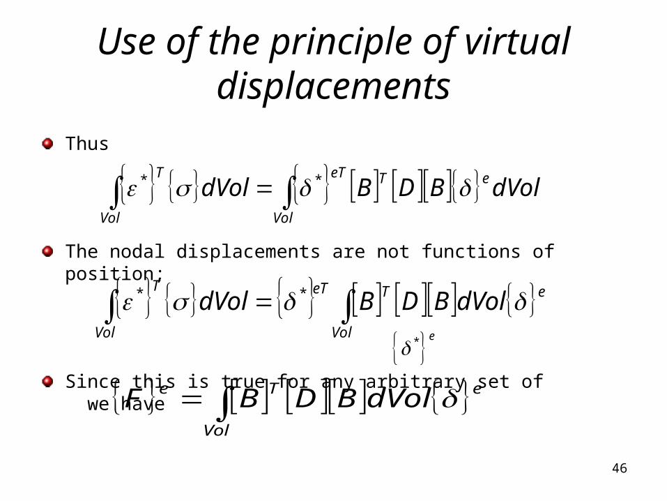
Use of the principle of virtual displacements
Thus
The nodal displacements are not functions of position;
Since this is true for any arbitrary set of we have
dVolBDBdVol eTeT
Vol
T
Vol
**
eVol
TeTT
Vol
dVolBDBdVol **
eVol
Te dVolBDBF
* e

47
Use of the principle of virtual displacements
This is the finite element equation for the element
From the definition of the element stiffness matrix,
by comparing previous equations we have the stiffness matrix
eVol
Te dVolBDBF
eee KF
Vol
Te dVolBDBK

48
Use of the principle of virtual displacements
u and v are linear functions of x and y
The strains and stresses are therefore constant
[B]T[D][B] is thus constant
The components of [K]e are therefore the components of [B]T[D][B]
multiplied by the volume of the element
In other higher order elements this is not strictly true and numerical
methods of integration are frequently used
[K]e must be symmetrical ([K]eT=[K]e)
49
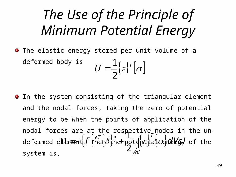
The Use of the Principle of Minimum Potential Energy
The elastic energy stored per unit volume of a deformed body is
In the system consisting of the triangular element and the nodal
forces, taking the zero of potential energy to be when the points of
application of the nodal forces are at the respective nodes in the
un-deformed element. Then the potential energy of the system is,
TU2
1
dVolFT
Vol
eeT 2
1

50
The Use of the Principle of Minimum Potential Energy
The potential energy can be written as,
and are constant over the element and can be taken
outside the integral
Vol
eTeTeeT dVolBDBF 2
1
eVol
TeTeeT dVolBDBF 2
1
* e * eT

51
The Use of the Principle of Minimum Potential Energy
Let us denote the square 6x6 matrix in the integral by [A]
In equilibrium is a minimum with respect to any of the nodal
displacements
Vol
T dVolBDBA
0.....
mii vvu
52
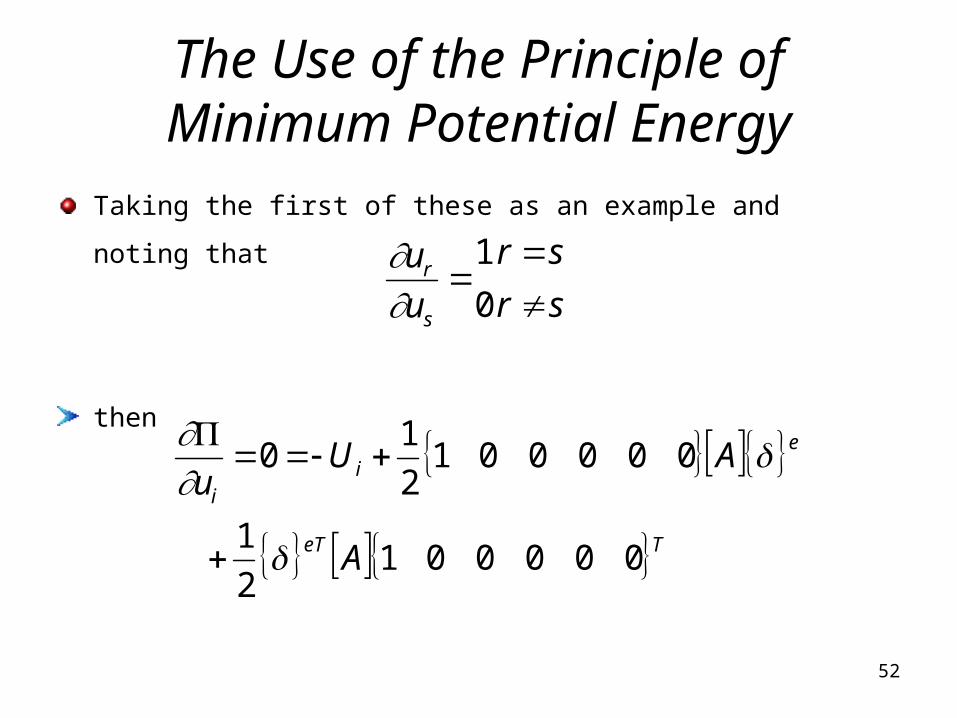
The Use of the Principle of Minimum Potential Energy
Taking the first of these as an example and noting that
then
sr
sr
u
u
s
r
0
1
TeT
ei
i
A
AUu
0000012
1
0000012
10

53
The Use of the Principle of Minimum Potential Energy
This can be written explicitly as
It has been noted that [A] is symmetrical and the last two terms of
this equation are therefore equal
Aofcolumnfirst
AofrowfirstUu
eT
ei
i
2
1
2
1
ei AofrowfirstU 2
1

54
The Use of the Principle of Minimum Potential Energy
In general
By comparing this with the equation
we see that
ei AF
eVol
Te dVolBDBF
e T
V
K A B D B dV

55
The Use of the Principle of Minimum Potential Energy
In this particular case of the uniform-strain triangular element, since
the integral is a constant in this equation
It can be written as
is the area of the triangular element and t is its thickness
ei AF
tBDBK Te