Embed Size (px)
Citation preview

1
2
1.0 BICC Cables Background 1.1 Introduction 6 1.2 Ordering Advices 7 1.3 Technical Advisory Service 7 2.0 BICCCablesQualifications 2.1 Performance 8 2.2 Safety 8 2.3 ISO 9001:2015 9
3.0 ProductConstruction 3.1 Conductors 10 3.2 Insulation 10 3.3 CoreIdentification 11 3.4 Fillers 11 3.5 Binding Tape 11 3.6 Bedding 12 3.7 Armour 12 3.8 Oversheath 13 3.9 Product code 15
4.0 Installation 4.1 Sheath Damage 16 4.2 Minimum Bending Radius 16 4.3 Connectors 16 4.4 Overhead Terminations 16 4.5 Cable Support Spacing 17
5.0 CurrentRating 5.1 Source of Data 18 5.2 Installation Environment 18 5.3 IEE Wiring Regulations 18th Edition 19
6.0 VoltageDrop 21
7.0 ShortCircuitRatings 7.1 XLPE & PVC Insulated Cables Copper Conductor 23 7.2 XLPE & PVC Insulated Cables Aluminum Conductor 24 7.3 Armour 25
8.0 CableRatingFactors 8.1 Cables laid directly in ground 26 8.2 Cables laid in ducts 29
CONTENTS
GENERALINFORMATION&TECHNICALDATA

3
9.0 TechnicalDataTables 9.0 Data Tables For PVC & XPLE lnsulation Cables 34
10.0 OverheadConductors 10.1 All Aluminum Conductors (AAC) 98 10.2 Aluminum Conductor Steel Reinforced (ACSR) 103 10.3 Bare Copper Conductors (BC) 108
11.0 Glossary 112
POWERCABLES
6
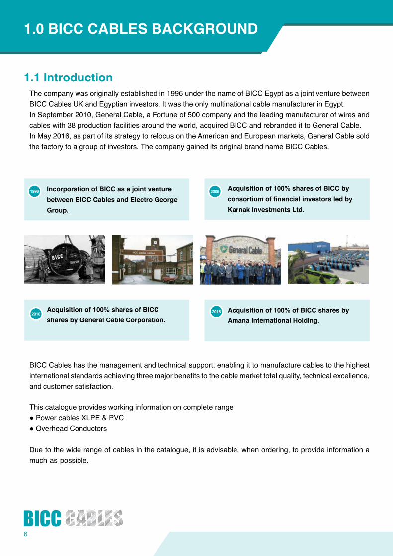
Acquisitionof100%sharesofBICCbyconsortiumoffinancialinvestorsledbyKarnakInvestmentsLtd.
2005
1.1IntroductionThe company was originally established in 1996 under the name of BICC Egypt as a joint venture between BICC Cables UK and Egyptian investors. It was the only multinational cable manufacturer in Egypt.In September 2010, General Cable, a Fortune of 500 company and the leading manufacturer of wires and cables with 38 production facilities around the world, acquired BICC and rebranded it to General Cable.In May 2016, as part of its strategy to refocus on the American and European markets, General Cable sold the factory to a group of investors. The company gained its original brand name BICC Cables.
BICC Cables has the management and technical support, enabling it to manufacture cables to the highest internationalstandardsachievingthreemajorbenefitstothecablemarkettotalquality,technicalexcellence,and customer satisfaction.
This catalogue provides working information on complete range ●PowercablesXLPE&PVC●OverheadConductors
Due to the wide range of cables in the catalogue, it is advisable, when ordering, to provide information a much as possible.
1.0BICCCABLESBACKGROUND
IncorporationofBICCasajointventurebetweenBICCCablesandElectroGeorgeGroup.
1996
Acquisitionof100%sharesofBICCsharesbyGeneralCableCorporation.
2010 Acquisitionof100%ofBICCsharesbyAmanaInternationalHolding.
2016
7
1.2OrderingAdvicesThe following details will ensure that your inquiries andordersarehandledquicklyandefficiently1. Length of cables required and individual drum lengths. ⁕
2. Voltage designation.3. Relevant British or International standard.4. Number of cores.5. Color code & color sequence ( Phase colors and neutral color ).6. Conductor size, where applicable and size of reduced neutral conductor.7. Conductor material i.e. Copper, Aluminum.8. Conductortype(solidclass1,strandedclass2orFlexiblestrandclass5).9. Type of insulation (PVC, XLPE and Special compounds) 10. Type of bedding11. Fire Resistance Cables According to IEC 60331 and BS 6387.12. Type of armour (STA, GSWA, AWA, STA+SWA, .... )13. Type of outer sheath ( PVC, Reduced Flame Propagation PVC, LSF & LSOH or LSHF.... )14. Any other requirement, e.g. (circular conductors, special PVC sheath material, drum weight limitation, etc.)⁕Cablesarenormallysuppliedinlengthof1000metersupto95mm2 and 500 meters for larger sizes.
Other lengths can be supplied if required. ⁕Singlecorecablesnormallyinlengthsof1000metersupto240mm2 & 500 meters for larger sizes.
1.3TechnicalAdvisoryServiceSpecialist advice on all matters concerning electrical power cables is available from BICC Cables sales team or direct from:-
BICC Cables is committed to supplying its customers with the highest quality of product and service. BICC Cables have undergone rigorous type testing by ERA Technology Ltd and the British Standard institution (via BASEC of the UK) and fully conform to IEC 60502 for electricity supply up to including 1.8 /3.3 kV ratings.
BICCCablesS.A.E,HeadOffice:34 Block A 1st District Services CenterNew Cairo, Egypt Tel :(202) 22471677 / 22471699 Fax.:(202)22472011Website: www.bicccables.comE-mail: [email protected]
Factory: Industrial Zone, Abu Rawash Km 28 Cairo AlexandriaDesertRoadCairo,EgyptTel. :(202) 3539 0251,2,3,4 Fax:(202)35390255,6E-mail: [email protected]
8
2.1PerformanceBICC Cables can provide optimum cables performance, and has access to the latest development in conductor, insulation and protectivematerials technology. Our experienced technical staff can provideguidance on cable selection and installation.
Where necessary, special features can be incorporated into the cable enabling it to have:
●Improvedfire performance. ●Lowsmokeandfume(Halogenfree).●Termiteresistance,●Resistancetoattackfromoils,solventsorcorrosivechemicals.
BICC Cables Technical Engineerswillbeglad toprovideassistance toensureyouget the rightcable that fully complieswith your applications.
Specifying the right cable for a particular applicationisthefirst step. However, the key to reliability is in the manufacturing process. The cable must be from high quality material and manufactured ensuring that no defects or weaknesses will be revealed in service.
BICC Cables constantly monitors all manufacturing processes and operates the most stringent quality assuranceprocedurestogiveyouexcellentreliability.Itisafactorwhichassumesvitalsignificancewhencablesaretobeinstalledinlocationswherefutureaccesswouldbedifficult.ThatiswhenBICCcablesandresources will give peace of mind.
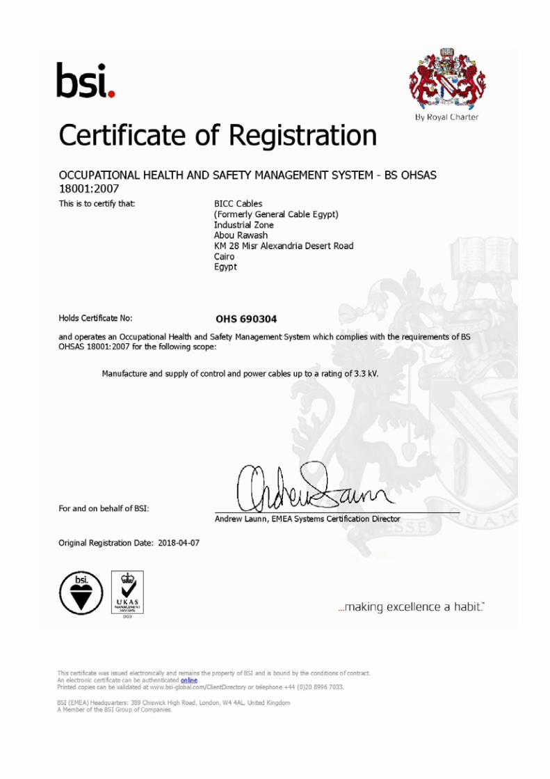
2.2Safety BICC Cables is able to maintain a close watch on development in cable technology and regulations, and therefore ensure that our products are designed and constructed to be hazard free under the prescribed conditions of use.
BICC Cables uses only tried and tested materials and processes in full compliance with all the relevant British and International standards. therfore, our cables are manufactured for safe use, without the risk tohealth,on theunderstanding thatuserswill exercise thesamedegreeofcare in their selectionandapplication.
Industrial safety is also an important issue with BICC Cablesandisstrictlyappliedtothecompany’sownoperations.
2.0BICCCABLESQUALIFICATIONS
9
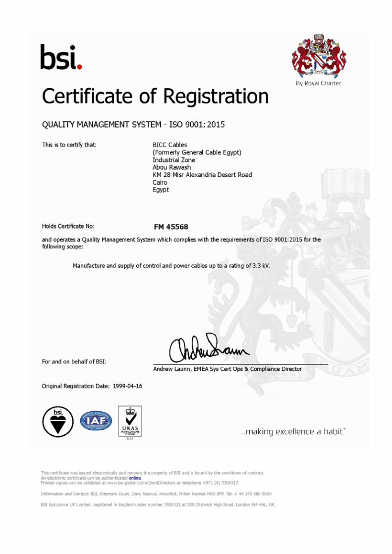
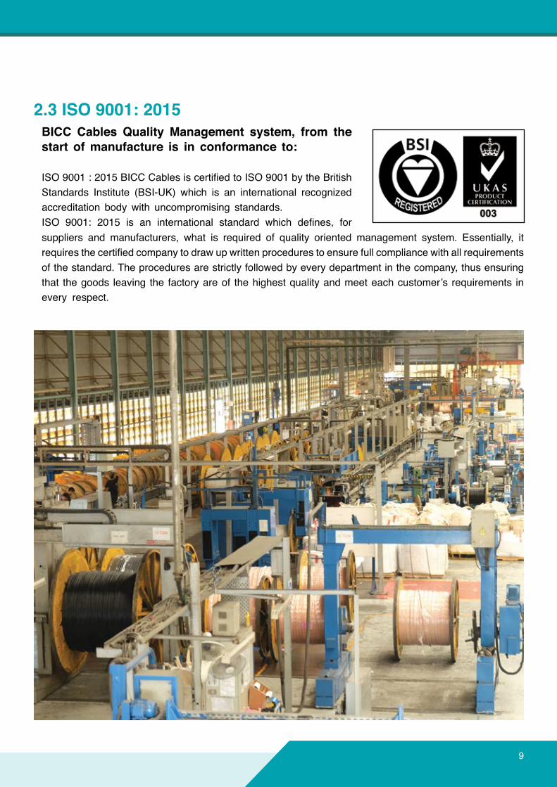
2.3 ISO 9001: 2015BICC Cables Quality Management system, from thestart ofmanufacture is in conformance to:
ISO9001:2015BICCCablesiscertifiedtoISO9001bytheBritishStandards Institute (BSI-UK) which is an international recognized accreditation body with uncompromising standards. ISO 9001: 2015 is an international standard which defines, forsuppliers and manufacturers, what is required of quality oriented management system. Essentially, it requiresthecertifiedcompanytodrawupwrittenprocedurestoensurefullcompliancewithallrequirementsof the standard. The procedures are strictly followed by every department in the company, thus ensuring that thegoods leaving the factoryareof thehighestqualityandmeeteachcustomer’s requirements inevery respect.
10
The PVC & XLPE insulated power cables details in this publication are rated at 0.6/1 kV. Details of BICC Cables 1.8/3.3 kV rated cables are available on request. Both steel tape and steel wire armoured and unarmoureddesignsareincluded.TheseconformspecificallytoIEC60502,Cablescanalsobesuppliedtothe National Standards of other countries.
3.1Conductors It is the current carrying component of the cable. TheconductorsinBICCCablesfixedpowercablesareofhighconductivitycopperorhighpurityaluminiumand all meet the requirements of IEC60228 “Conductors in insulated cables and cords”.Theflexibilitydegreeisdescribedas:
●Conductortoclass1(solidconductor,wherenostrandwires).●Conductortoclass2(strandedwireslike7wires,19wires,37wires,and61wires).●Conductortoclass5(morenumberofwiresinsidetheconductortomaketheconductorflexible).●Conductortoclass6(likeclass5,butwithmorenumberofwiresandmoreflexibletobeusedincords).
Dependent upon the actual cable type, conductors may be stranded copper or aluminium. Smaller sizes are circularinprofile;largerconductorsareshapedortightlycompactedtoreducetheirphysicalsize.This compacting sometimes entails a change in the number and size of wires and therefore conductors aregenerallycategorizedbytheirnominalcrosssectionalarearatherthanbytheirstrandingconfiguration.
3.2InsulationIn accordance with this technical guide, cables are insulated with PVC (Polyvinyl Chloride) or XLPE( Cross Linked Polyethylene ) or Low Smoke Zero Halogen (LSOH).
PVCInsulationPVC as per IEC 60502 is a clean, easy to handle material with good electrical characteristics and resistance towater,oilsandchemicals,togetherwithinherenttoughnessandflexibilityoverawidetemperaturerange.PVC cables are easy to handle joints, terminates and have an outstanding record of trouble free service.
PVCisinherentlyflameretardantandissuitableforamaximumoperatingtemperatureof70OC.
All of thecablesinthispublicationmeettherequirementsofIEC60332,“Testonelectricalcablesunderfirecondition”, part 1 “Method of test on a single vertical insulated wire or cables”.
Under someunfavorable circumstancesPVCcanburnandfiremay even propagate along the cables. However,typesofoversheathincorporatingspecialdevelopedcompoundstoovercomefirehazardsareavailable,asdescribedlater‘oversheath’.Additionalinformationandquotationsfortheseoversheathwillbe supplied upon request.
3.0PRODUCTCONSTRUCTION
11
XLPEInsulation Cross linked polyethylene ( XLPE ) type GP 8 as per BS 7655 and IEC 60502 requirements. XLPEmatchesmanyoftheattributesofPVC,althoughitisnotflameretardant,butgoesastageortwofurther. The good qualities of polyethylene are retained but at high temperatures the toughness and physical properties are improved. In particular, there is greatly enhanced resistance to deformation. Having superior thermal and mechanical properties compared with PVC, the XLPE also has higher insulation resistance, enabling its thickness to be reduced, leading to corresponding reduction in the overall diameter andweightofafinishedcable.The main comparative consideration however, is that XLPE permits the operating temperature of cables to be raised substantially without suffering thermal deformation or degradation. ThecontinuouscurrentratingofXLPEinsulatedcablesarebaseduponamaximumconductortemperatureof90 OC as opposite to 70 OC for PVC insulated types. Short circuit rating are also higher, XLPE accepted 250 OCasafinalconductortemperatureattheendofshort circuit compared with 140/160 OC for PVC insulated cables. As a result, in situations where conductor size is governed by current rating rather than voltage drop,itmaybepossibletouseasmallerconductorsize.
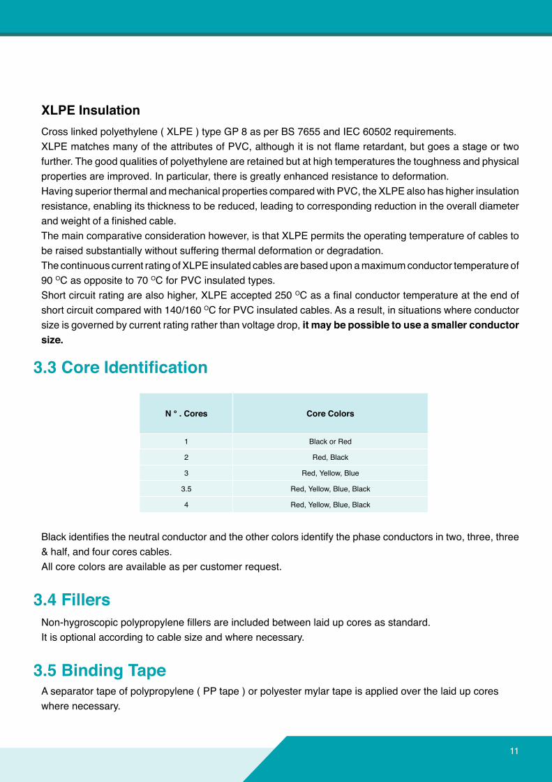
3.3CoreIdentification
Blackidentifiestheneutralconductorandtheothercolorsidentifythephaseconductorsintwo,three,three& half, and four cores cables. All core colors are available as per customer request.
3.4FillersNon-hygroscopicpolypropylenefillersareincludedbetweenlaidupcoresasstandard.It is optional according to cable size and where necessary.
3.5BindingTapeA separator tape of polypropylene ( PP tape ) or polyester mylar tape is applied over the laid up coreswhere necessary.
N ° . Cores Core Colors
1 Black or Red
2 Red, Black
3 Red, Yellow, Blue
3.5 Red, Yellow, Blue, Black
4 Red, Yellow, Blue, Black
12
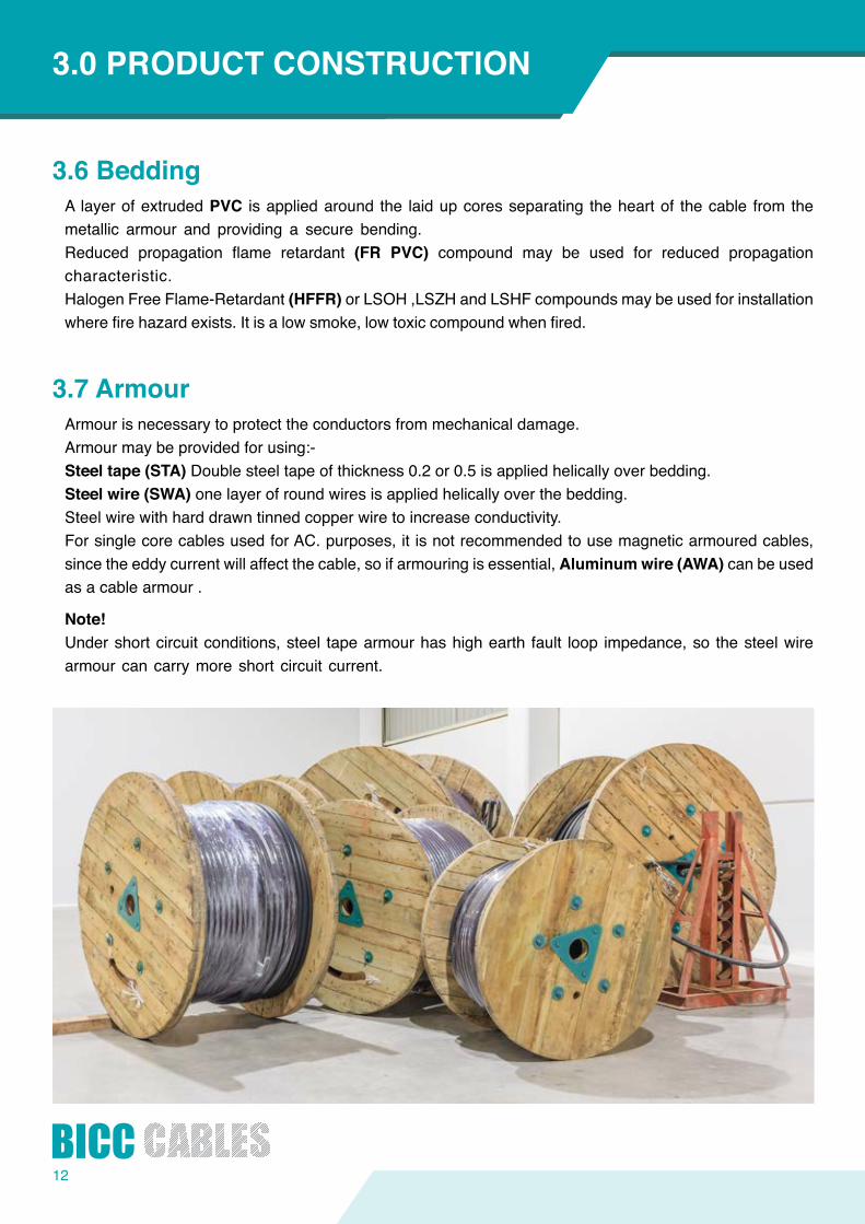
3.6 Bedding A layerofextrudedPVC is applied around the laid up cores separating the heart of the cable from the metallic armour and providing a secure bending. Reduced propagation flame retardant (FR PVC) compound may be used for reduced propagation characteristic. Halogen Free Flame-Retardant (HFFR) or LSOH ,LSZH and LSHF compounds may be used for installation wherefirehazardexists.Itisalowsmoke,lowtoxiccompoundwhenfired.
3.7ArmourArmour is necessary to protect the conductors from mechanical damage.Armour may be provided for using:-Steeltape(STA) Double steel tape of thickness 0.2 or 0.5 is applied helically over bedding. Steelwire(SWA) one layer of round wires is applied helically over the bedding. Steel wire with hard drawn tinned copper wire to increase conductivity. For single core cables used for AC. purposes, it is not recommended to use magnetic armoured cables, since the eddy current will affect the cable, so if armouring is essential, Aluminumwire(AWA) can be used as a cable armour .
Note!Under short circuit conditions, steel tape armour has high earth fault loop impedance, so the steel wire armour can carry more short circuit current.
INTRODUCTION3.0PRODUCTCONSTRUCTION
13
3.8OversheathPVC The standard sheath of all cables is an extruded layer of blackPVC, the external surface ofwhich isembossed with voltage, rating and cable size. Normally the over sheath PVC grade meets the requirements of BS 7655. Other grades can be used dependent upon customer requirements e.g. PVC sheath withanti-termitepropertiescanbeprovidedwhenspecified.
Ordinary PVC is intrinsically flame retardant and all cables described in this publication meet the requirementsofIEC60332part1“Testsonelectriccablesunderfireconditionsonasingleverticalinsulatedwire or cable”.
Forenhancedfireperformance,specialPVCsheathcompoundsareavailable,e.g.Reduced Propagation (FR-PVC) and Reduced Propagation &low Hydrochlochloric acid gas emissions (FRLHCL) PVC compounds can be offered as a sheathing material.
PVC and XLPE insulated armoured cables with FR, FRLHCL bedding and sheath will pass the test requirementsundercategoryCofIEC60332Part3specificationfor“testonelectricalcablesunderfireconditiononbunchedwiresorcables”.ForIEC60332Part3categoriesAandB,meetingthespecificationdepends primarily on the type, size and number of cables in the bunched cable installation that make up the total volume of non metallic components.PleaseseekadvicefromourTechnicalDepartmentforspecificinstallations.
HalogenFreeFlameRetardant(HFFR),LowSmoke&Fume(LSF)andLowSmokeZeroHalogen(LSOH,LSZHorLSHF).BICC Cables is manufacturing a dedicatedcablecalledHFFR,whichisLowSmoke,Lowtoxicemissionand low Fume.
This cable is specially installed wherefireanditsassociatedproblems-theemissionofsmokeandtoxicfumes-offeraseriouspotentialthreat.HFFRcompoundisfreefromhalogen(fluorine,chlorineandbromine).BICC Cables can provide the customer with this type of cables that:
●Are manufactured to BS 6724. ●Haveminimumlimitedoxygenindex(LOI)is32%forbeddingandoversheath(measuredasper BS 2782 / ISO 4589 - A-IV). ●HavelowHCLemission.●Haveacidicgasevolutionoflessthan0.5%(toBS2782).●ComplytoIEC60332-3(CableconstructionanddesignshouldbeagreedbyBICCCables).
PleaserefertoBICCCablestechnicaldepartmentforadviceaboutthesubject.
14
SpecialtypesofoverSheath(Jacketing)If your application requires special protection for the cable, other material for sheathing jacketing may be
considered. BICC Cables technical department will be glad to provide you with the best cable selection that
willfittheapplication.
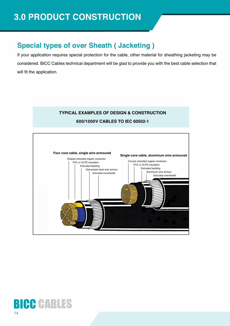
TYPICALEXAMPLESOFDESIGN&CONSTRUCTION
600/1000VCABLESTOIEC60502-1
INTRODUCTION3.0PRODUCTCONSTRUCTION
Shaped stranded copper conductor PVC or XLPE insulation Extrudedbedding Galvanised steel wire armourExtrudedoversheath
Fourcorecable,singlewirearmouredSinglecorecable,aluminiumwirearmoured
Circular stranded copper conductor PVC or XLPE insulationExtrudedbedding Aluminium wire armourExtrudedoversheath
15
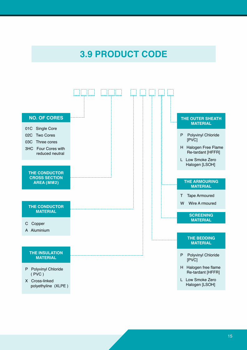
3.9PRODUCTCODE
NO.OFCORES
THECONDUCTORCROSSSECTIONAREA(MM2)
THECONDUCTORMATERIAL
THEOUTERSHEATHMATERIAL
THEARMOURINGMATERIAL
SCREENINGMATERIAL
THEBEDDINGMATERIAL
THEINSULATIONMATERIAL
01C Single Core02C Two Cores 03C Three cores 3HC Four Cores with reduced neutral
P Polyvinyl Chloride [PVC]
H Halogen Free Flame Re-tardant [HFFR]
L Low Smoke Zero Halogen [LSOH]
P Polyvinyl Chloride [PVC]
HHalogenfreeflame Re-tardant [HFFR]
L Low Smoke Zero Halogen [LSOH]
T Tape Armoured
W Wire A rmoured
C Copper A Aluminium
P Polyvinyl Chloride ( PVC )X Cross-linked polyethyline (XLPE )
16
All the cables described in this publication can be used outdoors, but some reservations are necessary concerning cables without a metal sheath for direct burial e.g. ●Unarmouredcablesarenotrecommendedforlayingdirectintheground.●Cables for layingdirectly in thegroundparticularly insustainedwetconditionsshouldhaveextruded bedding. ●Forinstallationwherethereiswaterlogging,orwhereitislikelytooccur,adviceshouldbeobtained from our technical department.
Otherimportantfactorstobetakenintoaccountare:
4.1SheathDamageCare should be taken to ensure that the oversheath is not damaged during installation. This is especially important where aluminium armour is used since ingress of moisture could lead to corrosion and loss of earth continuity.
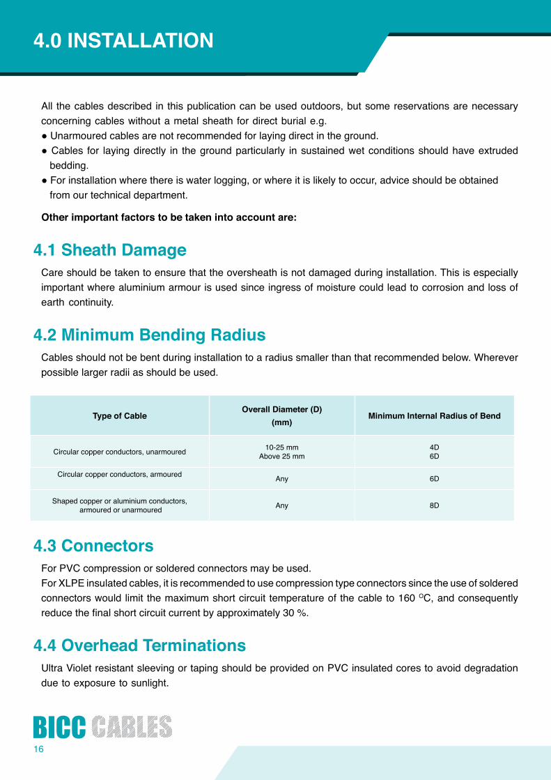
4.2MinimumBendingRadiusCables should not be bent during installation to a radius smaller than that recommended below. Wherever possible larger radii as should be used.
4.3ConnectorsFor PVC compression or soldered connectors may be used. For XLPE insulated cables, it is recommended to use compression type connectors since the use of soldered connectorswouldlimitthemaximumshortcircuittemperatureofthecableto160OC, and consequently reducethefinalshortcircuitcurrentbyapproximately30%.
4.4OverheadTerminationsUltra Violet resistant sleeving or taping should be provided on PVC insulated cores to avoid degradation duetoexposuretosunlight.
INTRODUCTION4.0INSTALLATION
TypeofCableOverallDiameter(D)
(mm)MinimumInternalRadiusofBend
Circular copper conductors, unarmoured 10-25 mmAbove 25 mm
4D6D
Circular copper conductors, armoured Any 6D
Shaped copper or aluminium conductors, armoured or unarmoured Any 8D
17
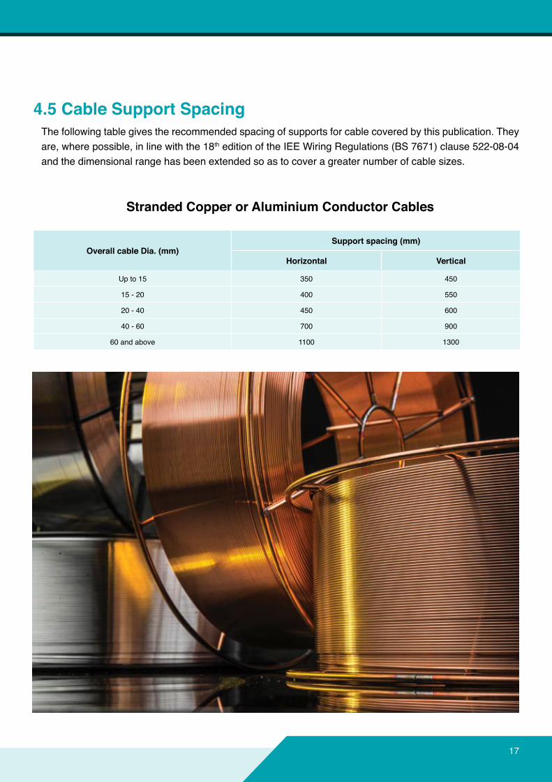
4.5CableSupportSpacingThe following table gives the recommended spacing of supports for cable covered by this publication. They are, where possible, in line with the 18th edition of the IEE Wiring Regulations (BS 7671) clause 522-08-04 andthedimensionalrangehasbeenextendedsoastocoveragreaternumberofcablesizes.
StrandedCopperorAluminiumConductorCables
OverallcableDia.(mm)Supportspacing(mm)
Horizontal Vertical
Up to 15 350 450
15 - 20 400 550
20 - 40 450 600
40 - 60 700 900
60 and above 1100 1300
18
5.1SourceofDataThemaximumsustainedcurrent rating (AC) forcopperandaluminiumconductorcablesgiven forPVCinsulated cables, in this publication are based, where applicable, on ERA report 69-30 Part Ill (Sustained Current Ratings for PVC Insulated cables).
For XLPE insulated cables, the current rating in this publication are derived from the latest issue of ERA report no. 69-30 part 5, which is based upon IEC 287.
All other current ratings have to be calculated by agreed formula and methods in IEC 287 and/or the IEE wiring regulations 18th Edition (BS 7671).Current rating or unrmoured cables are based on IEC Publication 364-5-523 (1983) and IEE WiringRegulations 18th Edition.
In the case of single core cables, ratings for various installation conditions have been given. Where the cables are armoured, these are based on the assumption that the non-magnetic armour will be solidly bonded at both ends of the cable run. It should be noted that Regulation 521-02 of the 18th Edition o the IEE Wiring Regulation prohibits the use of single core cables with steel wire on AC systems.
All the current ratings given in data tables are or single circuits, thermally independent of other circuits or any other heat source and on the basis of the standard conditions of installation given. Forotherambientorgroundtemperatures,depthoflayingandsoilfactorsgivenindatatables.
5.2InstallationEnvironmentThere are three main installation conditions that affect the current rating of a cable and these are: 1. Cables laid directly in the ground. 2. Cables laid in ducts. 3. Cables laid in free air.
Current ratings for PVC and XLPE insulated cables are listed in the relevant tables in data tables and refer to standard conditions of installation, for single circuits, as detailed in ERA report 96.30 part 3 and part 5, for ground and duct installation. For installation in air, values are relevant to IEE wiring regulations(18th Edition).
For other ambient or ground temperatures, change in depth of laying, soil thermal resistivity or number of grouping cables, the current rating must be multiplied by relevant rating factors Listed in data tables.
INTRODUCTION5.0CURRENTRATINGS
19
5.3IEEWiringRegulation18thedition-RequirementforCablesThe IEE wiring regulations for installation and selection of cables cannot be approached in isolation from the other equipment in the installation. In particular the devices providing protection against overload, short circuit and shock by indirect contact and overheating of protective conductors during an earth fault affect the selection of cables. For guidance and assistance, some of the IEE Wiring regulations requirements for cables are giving below:
5.3.1ProtectionagainstOverloadCurrent,lEEWiringRegulation433The two requirements which determine the sustained current rating required are: (i) The current rating of the cable should not be less than the nominal current or current setting of thedevice providing protection against overload current which in turn should not be less than the circuit current.(ii) The overload protection should operate at not more than 1.45 times the current rating of the cable.
The second requirement (ii) is metifthefirst(i)issatisfiedwhentheprotectivedeviceisanyofthestandardfusesormaincircuitbreakers(MCB)mentionedintheregulation,exceptrewirabletypesoffusetoBS 3036. With fuses to BS 3036 the current ratings of the cable should not be less than 1.38 times the fuse rating to satisfy (ii).
5.3.2Protectionagainstshortcircuit,IEEwiringRegulation434The cable has to have adequate short circuit capacity for the current let through by the device providing shortcircuitprotectionforthetimeitwillflow.
The formula in section 434-03-03 is that used cable makers to give the short circuit ratings in their publication.
If the device providing protection against short circuit is the same as that providing protection against overload and, therefore, has a rating not higher than the rating of the cables, the short circuit capacity of the cable will automatically be adequate, there is no need to check.
5.3.3Protectionagainstindirectcontactbyinterruptionofsupply,IEEWiringRegulation413Protectionagainstshockduetocontactwithexposedconductivepartsofequipmentduringafaulttoearthisdeemedtobeprovidedifdisconnectionduetoflowofthefaultcurrentthroughtheprotectivedevicewilloccur, either: Within0.4secondsforfinalcircuitssupplyingsocketoutletsorwithin5secondsforfinalcircuitssupplyingfixedequipment.Regulation 413 gives values of earth fault loop impedance which satisfy these conditions when the standard types of protective device are used. Cablesmakethemajorcontributiontoearthfaultloopimpedance,buttheimpedanceofthesupplyexternalto the installation has to be taken into account.
20
Itisnotpossibletosaywhatmaximumlengthofstandardcablesmaybeusedintheinstallationwithoutexceedingtherequirementsforearthfaultloopimpedanceintheabsenceofinformationontheexternalimpedance for the particular installation.
5.3.4CrosssectionareasofprotectiveconductorsIEEWiringRegulation543 Regulation543explainshowthecrosssectionalareaofthecircuitprotectiveconductorshouldbecalculatedto avoid it overheating during a fault to earth. Again the required depends on the characteristics of the device providing protection against short circuit. The steel wire armour standard cables to IEC 60502 (PVC) or BS 5467 (XLPE) provides the required area, ormore,whentheprotectivedeviceisoneofthestandardfusesorMCB’switharatingnothigherthanthecurrent rating of the cable (assuming disconnection within 5 seconds). For most of the cables the armour is still adequate when the fuse rating is one or two steps, or even more, above the current rating of the cable, the range being greater or the small sizes and 4 core cables than for the larger sizes and two cores cable.
INTRODUCTION5.0CURRENTRATINGS
21
6.0VOLTAGEDROPVoltage drop is normally only of importance for cables of voltage rating 0.6/1 KV or below. If the insulation is to be in compliance with regulation 525 of the 18th Edition of the IEE wiring regulations, it is stipulated thatthevoltagedropwithintheinstallationshouldnotexceedavalueappropriatetothesafefunctioningoftheassociatedequipmentinnormalservice.Therequirementisdeemedtobesatisfiedifthevoltagebetweentheoriginoftheinstallation(usuallysupplyterminals)andthefixedcurrentusingequipmentdoesnotexceed4%ofthenominalvoltageonthesupply,disregardingstartingconditions.(Note Diversity can be taken into account when calculating the voltage drop).
Since the actual power factor of the load is often not known, the most practical approach to the question of voltage drop is to assume the worst conditions, i.e. where the phase angle of the load is equal to that of the cable. The voltage drop values in the tables have been based on this assumption. For conductor sizes up toandincluding120mm2thefiguresprovidedapplythiswithsufficientaccuracywherethepowerfactorliesbetween0.6laggingand1.0andforlargecableswherethepowerfactoroftheloaddoesnotexceed0.8 lagging. Where the phase angles of the loads fall outside this range, the voltage drop deduced from the tablesmaybeundulyconservativeandmoreexactmethodsofcalculationshouldbeemployed.
The valueofvoltagedropfor0.6/1KVrated cablesaregiveninthecurrentratingtablesindatatables.
In those cases where the actual current differs greatly from the tabulated current rating, the results obtained fromthetableareonlyapproximate;foramoreaccurateassessmentallowanceshouldbemadeforthechange in conductor resistance with operating temperature. (FurtherinformationcanbegainedfromtheTechnicalDepartmentofBICCCables).
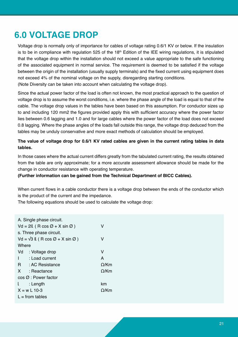
Whencurrentflowsinacableconductorthereisavoltagedropbetween the ends of the conductor which is the product of the current and the impedance. The following equations should be used to calculate the voltage drop:
A. Single phase circuit.Vd = 2ll ( R cos Ø + X sin Ø ) Vs. Three phase circuit.Vd=√3ll ( R cos Ø + X sin Ø ) VWhereVd : Voltage drop VI : Load current AR :ACResistance Ω/KmX :Reactance Ω/Km cos Ø : Power factor l : Length kmX=wL10-3 Ω/KmL = from tables
22
RelationbetweencosØandsinØ
Cos Ø 1.0 0.9 0.8 0.71 0.6 0.5
Sin Ø 0.0 0.44 0.6 0.71 0.8 0.87
INTRODUCTION6.0VOLTAGEDROP
●L.V.cablesystemsshouldbeplannedsoasnottoexceedvoltagedrop3-5%innormal operating condition.●VoltagedropdataforL.V.Cable(Single&MultiCore)aretabulatedintables.
23
7.0ShortCircuitRatings
7.1ShortCircuitRatingsforXLPE&PVCInsulatedCablesCopperConductor
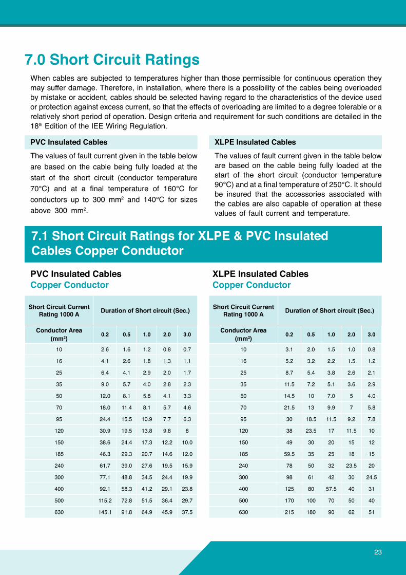
When cables are subjected to temperatures higher than those permissible for continuous operation they may suffer damage. Therefore, in installation, where there is a possibility of the cables being overloaded by mistake or accident, cables should be selected having regard to the characteristics of the device used orprotectionagainstexcesscurrent,sothattheeffectsofoverloadingarelimitedtoadegreetolerableorarelatively short period of operation. Design criteria and requirement for such conditions are detailed in the 18th Edition of the IEE Wiring Regulation.
PVCInsulatedCables
The values of fault current given in the table below are based on the cable being fully loaded at the start of the short circuit (conductor temperature 70°C) and at a final temperature of 160°C forconductors up to 300 mm2 and 140°C for sizes above 300 mm2.
PVCInsulatedCablesCopperConductor
XLPEInsulatedCablesCopperConductor
XLPEInsulatedCables
The values of fault current given in the table below are based on the cable being fully loaded at the start of the short circuit (conductor temperature 90°C)andatafinaltemperatureof250°C.Itshouldbe insured that the accessories associated with the cables are also capable of operation at these values of fault current and temperature.
ShortCircuitCurrentRating1000A DurationofShortcircuit(Sec.)
ConductorArea(mm2) 0.2 0.5 1.0 2.0 3.0
10 2.6 1.6 1.2 0.8 0.7
16 4.1 2.6 1.8 1.3 1.1
25 6.4 4.1 2.9 2.0 1.7
35 9.0 5.7 4.0 2.8 2.3
50 12.0 8.1 5.8 4.1 3.3
70 18.0 11.4 8.1 5.7 4.6
95 24.4 15.5 10.9 7.7 6.3
120 30.9 19.5 13.8 9.8 8
150 38.6 24.4 17.3 12.2 10.0
185 46.3 29.3 20.7 14.6 12.0
240 61.7 39.0 27.6 19.5 15.9
300 77.1 48.8 34.5 24.4 19.9
400 92.1 58.3 41.2 29.1 23.8
500 115.2 72.8 51.5 36.4 29.7
630 145.1 91.8 64.9 45.9 37.5
ShortCircuitCurrentRating1000A DurationofShortcircuit(Sec.)
ConductorArea(mm2) 0.2 0.5 1.0 2.0 3.0
10 3.1 2.0 1.5 1.0 0.8
16 5.2 3.2 2.2 1.5 1.2
25 8.7 5.4 3.8 2.6 2.1
35 11.5 7.2 5.1 3.6 2.9
50 14.5 10 7.0 5 4.0
70 21.5 13 9.9 7 5.8
95 30 18.5 11.5 9.2 7.8
120 38 23.5 17 11.5 10
150 49 30 20 15 12
185 59.5 35 25 18 15
240 78 50 32 23.5 20
300 98 61 42 30 24.5
400 125 80 57.5 40 31
500 170 100 70 50 40
630 215 180 90 62 51
24
INTRODUCTION7.0SHORTCIRCUITRATINGS
PVCInsulatedCablesAluminumConductor
XLPEInsulatedCablesAluminumConductor
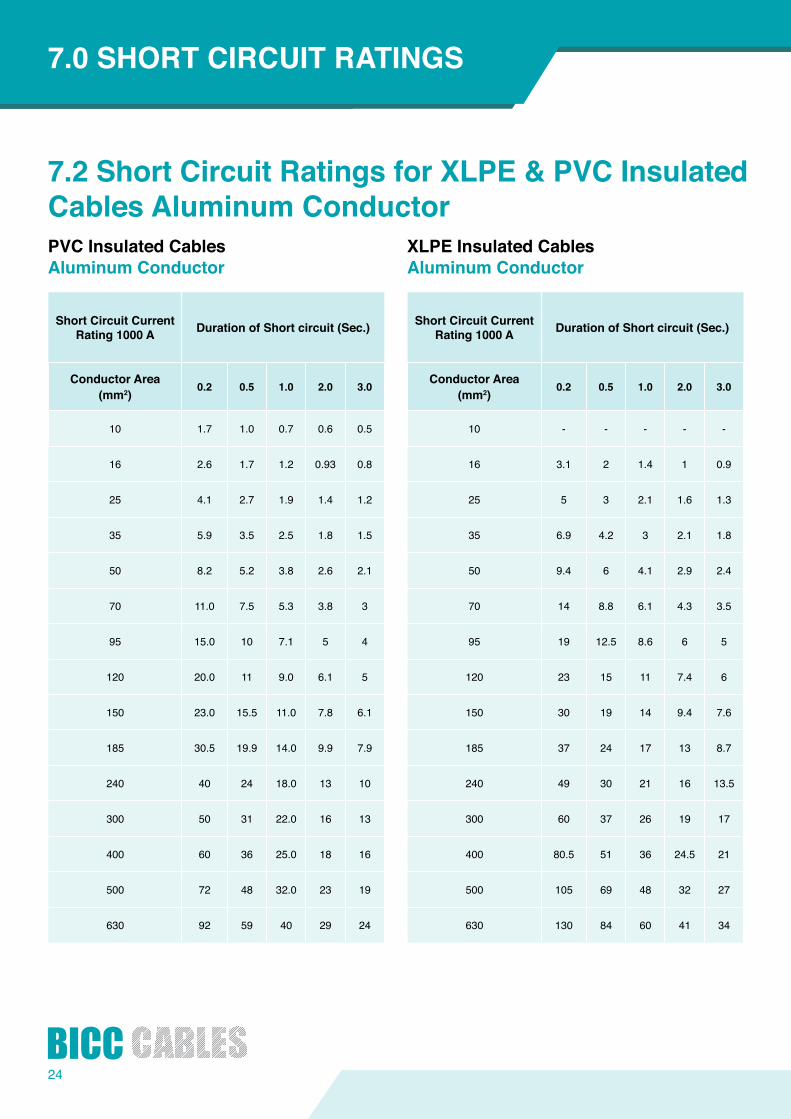
ShortCircuitCurrentRating1000A DurationofShortcircuit(Sec.)
ConductorArea(mm2) 0.2 0.5 1.0 2.0 3.0
10 1.7 1.0 0.7 0.6 0.5
16 2.6 1.7 1.2 0.93 0.8
25 4.1 2.7 1.9 1.4 1.2
35 5.9 3.5 2.5 1.8 1.5
50 8.2 5.2 3.8 2.6 2.1
70 11.0 7.5 5.3 3.8 3
95 15.0 10 7.1 5 4
120 20.0 11 9.0 6.1 5
150 23.0 15.5 11.0 7.8 6.1
185 30.5 19.9 14.0 9.9 7.9
240 40 24 18.0 13 10
300 50 31 22.0 16 13
400 60 36 25.0 18 16
500 72 48 32.0 23 19
630 92 59 40 29 24
ShortCircuitCurrentRating1000A DurationofShortcircuit(Sec.)
ConductorArea(mm2) 0.2 0.5 1.0 2.0 3.0
10 - - - - -
16 3.1 2 1.4 1 0.9
25 5 3 2.1 1.6 1.3
35 6.9 4.2 3 2.1 1.8
50 9.4 6 4.1 2.9 2.4
70 14 8.8 6.1 4.3 3.5
95 19 12.5 8.6 6 5
120 23 15 11 7.4 6
150 30 19 14 9.4 7.6
185 37 24 17 13 8.7
240 49 30 21 16 13.5
300 60 37 26 19 17
400 80.5 51 36 24.5 21
500 105 69 48 32 27
630 130 84 60 41 34
7.2ShortCircuitRatingsforXLPE&PVCInsulatedCablesAluminumConductor
25
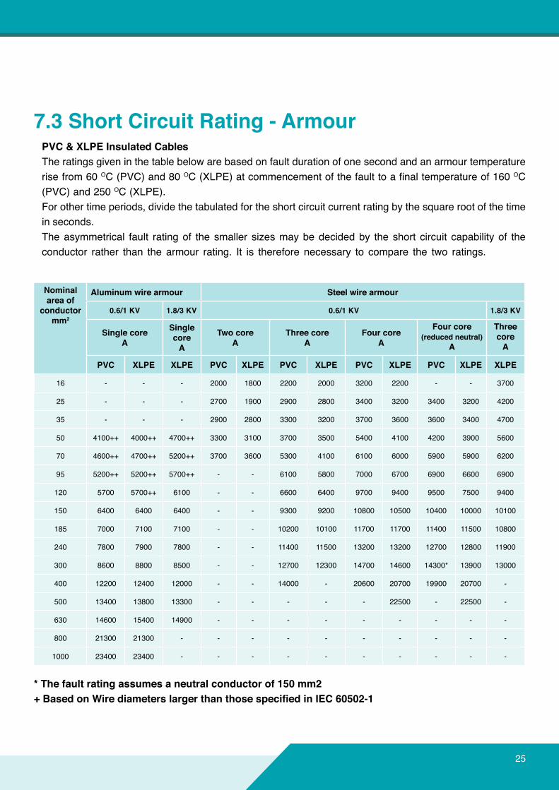
7.3ShortCircuitRating-ArmourPVC&XLPEInsulatedCablesThe ratings given in the table below are based on fault duration of one second and an armour temperature rise from 60 OC (PVC) and 80 OC(XLPE)atcommencementofthefaulttoafinaltemperatureof160OC (PVC) and 250 OC (XLPE).For other time periods, divide the tabulated for the short circuit current rating by the square root of the time in seconds.The asymmetrical fault rating of the smaller sizes may be decided by the short circuit capability of the conductor rather than the armour rating. It is therefore necessary to compare the two ratings.
*Thefaultratingassumesaneutralconductorof150mm2+BasedonWirediameterslargerthanthosespecifiedinIEC60502-1
Nominalareaof
conductormm2
Aluminumwirearmour Steelwirearmour
0.6/1 KV 1.8/3 KV 0.6/1 KV 1.8/3 KV
Single coreA
Single coreA
TwocoreA
Three coreA
FourcoreA
Fourcore(reducedneutral)
A
Three coreA
PVC XLPE XLPE PVC XLPE PVC XLPE PVC XLPE PVC XLPE XLPE
16 - - - 2000 1800 2200 2000 3200 2200 - - 3700
25 - - - 2700 1900 2900 2800 3400 3200 3400 3200 4200
35 - - - 2900 2800 3300 3200 3700 3600 3600 3400 4700
50 4100++ 4000++ 4700++ 3300 3100 3700 3500 5400 4100 4200 3900 5600
70 4600++ 4700++ 5200++ 3700 3600 5300 4100 6100 6000 5900 5900 6200
95 5200++ 5200++ 5700++ - - 6100 5800 7000 6700 6900 6600 6900
120 5700 5700++ 6100 - - 6600 6400 9700 9400 9500 7500 9400
150 6400 6400 6400 - - 9300 9200 10800 10500 10400 10000 10100
185 7000 7100 7100 - - 10200 10100 11700 11700 11400 11500 10800
240 7800 7900 7800 - - 11400 11500 13200 13200 12700 12800 11900
300 8600 8800 8500 - - 12700 12300 14700 14600 14300* 13900 13000
400 12200 12400 12000 - - 14000 - 20600 20700 19900 20700 -
500 13400 13800 13300 - - - - - 22500 - 22500 -
630 14600 15400 14900 - - - - - - - - -
800 21300 21300 - - - - - - - - - -
1000 23400 23400 - - - - - - - - - -
26
8.0CABLERATINGFACTORS
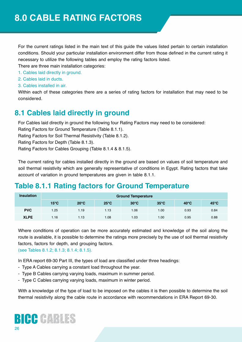
Forthecurrentratingslistedinthemaintextofthisguidethevalueslistedpertaintocertaininstallationconditions.Shouldyourparticularinstallationenvironmentdifferfromthosedefinedinthecurrentratingitnecessary to utilize the following tables and employ the rating factors listed.There are three main installation categories:1. Cables laid directly in ground.2. Cables laid in ducts.3. Cables installed in air.Within each of these categories there are a series of rating factors for installation that may need to be considered.
8.1CableslaiddirectlyingroundFor Cables laid directly in ground the following four Rating Factors may need to be considered:Rating Factors for Ground Temperature (Table 8.1.1).Rating Factors for Soil Thermal Resistivity (Table 8.1.2).Rating Factors for Depth (Table 8.1.3).Rating Factors for Cables Grouping (Table 8.1.4 & 8.1.5).
The current rating for cables installed directly in the ground are based on values of soil temperature and soil thermal resistivity which are generally representative of conditions in Egypt. Rating factors that take account of variation in ground temperatures are given in table 8.1.1.
Table8.1.1RatingfactorsforGroundTemperature
Where conditions of operation can be more accurately estimated and knowledge of the soil along the route is available, it is possible to determine the ratings more precisely by the use of soil thermal resistivity factors, factors for depth, and grouping factors.(seeTables8.1.2;8.1.3;8.1.4;8.1.5).
InERAreport69-30PartIII,thetypesofloadareclassifiedunderthreeheadings:- Type A Cables carrying a constant load throughout the year.-TypeBCablescarryingvaryingloads,maximuminsummerperiod.-TypeCCablescarryingvaryingloads,maximuminwinterperiod.
With a knowledge of the type of load to be imposed on the cables it is then possible to determine the soil thermal resistivity along the cable route in accordance with recommendations in ERA Report 69-30.
Insulation GroundTemperature
15°C 20°C 25°C 30°C 35°C 40°C 45°C
PVC 1.25 1.19 1.13 1.06 1.00 0.93 0.84
XLPE 1.16 1.13 1.08 1.03 1.00 0.95 0.88
27
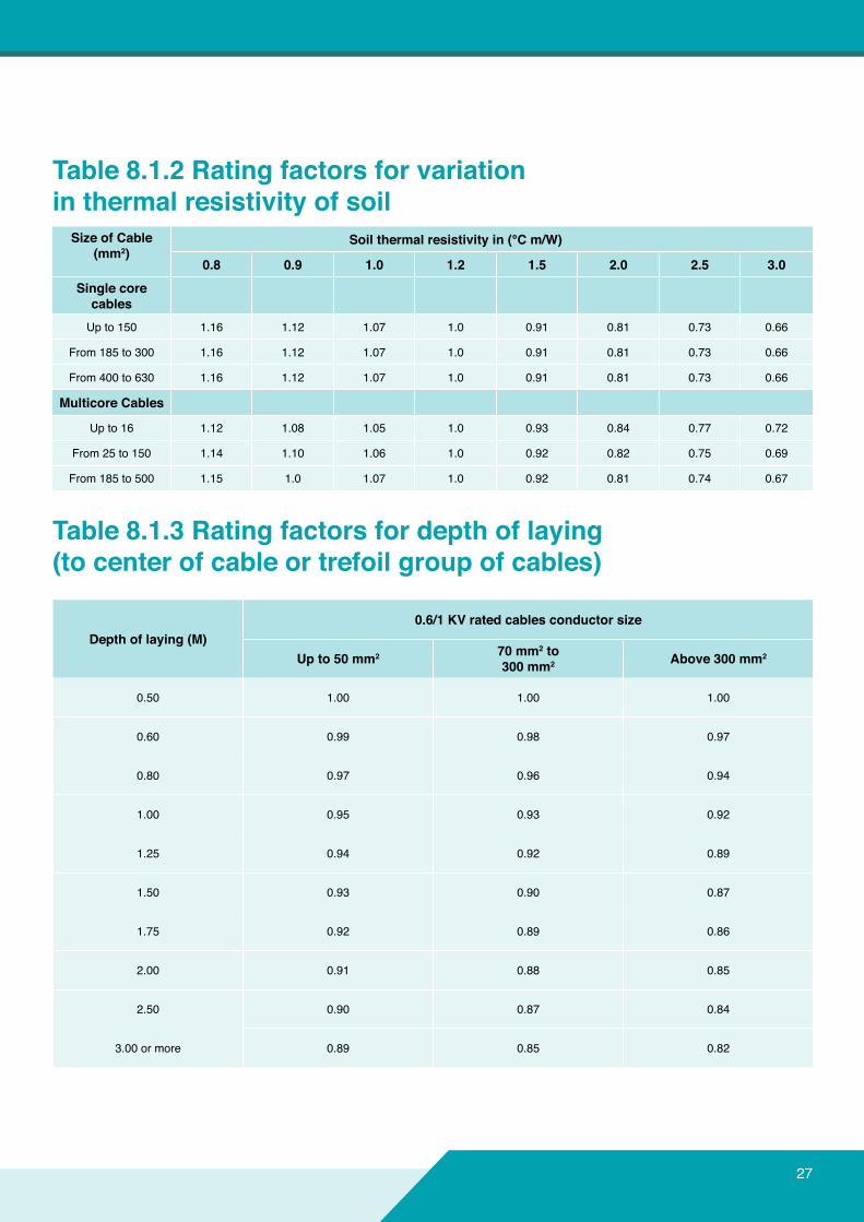
Table8.1.2Ratingfactorsforvariationinthermalresistivityofsoil
Table8.1.3Ratingfactorsfordepthoflaying(tocenterofcableortrefoilgroupofcables)
Depthoflaying(M)0.6/1KVratedcablesconductorsize
Upto50mm2 70mm2to300mm2 Above300mm2
0.50 1.00 1.00 1.00
0.60 0.99 0.98 0.97
0.80 0.97 0.96 0.94
1.00 0.95 0.93 0.92
1.25 0.94 0.92 0.89
1.50 0.93 0.90 0.87
1.75 0.92 0.89 0.86
2.00 0.91 0.88 0.85
2.50 0.90 0.87 0.84
3.00 or more 0.89 0.85 0.82
SizeofCable(mm2)
Soilthermalresistivityin(°Cm/W)
0.8 0.9 1.0 1.2 1.5 2.0 2.5 3.0Single core
cablesUp to 150 1.16 1.12 1.07 1.0 0.91 0.81 0.73 0.66
From 185 to 300 1.16 1.12 1.07 1.0 0.91 0.81 0.73 0.66
From 400 to 630 1.16 1.12 1.07 1.0 0.91 0.81 0.73 0.66
MulticoreCables
Up to 16 1.12 1.08 1.05 1.0 0.93 0.84 0.77 0.72
From 25 to 150 1.14 1.10 1.06 1.0 0.92 0.82 0.75 0.69
From 185 to 500 1.15 1.0 1.07 1.0 0.92 0.81 0.74 0.67
28
8.0CABLERATINGFACTORS
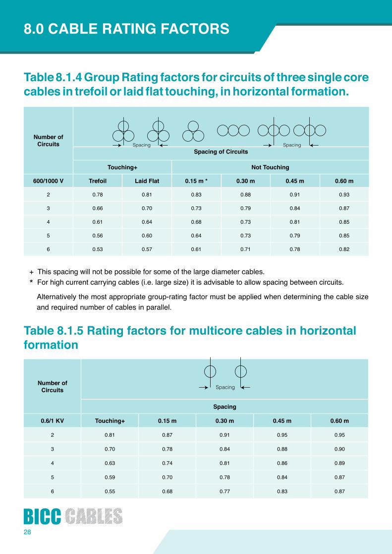
Table8.1.4GroupRatingfactorsforcircuitsofthreesinglecorecablesintrefoilorlaidflattouching,inhorizontalformation.
Table8.1.5Ratingfactorsformulticorecablesinhorizontalformation
+ This spacing will not be possible for some of the large diameter cables.* For high current carrying cables (i.e. large size) it is advisable to allow spacing between circuits.
Alternatively the most appropriate group-rating factor must be applied when determining the cable size and required number of cables in parallel.
NumberofCircuits
SpacingofCircuits
Touching+ NotTouching
600/1000 V Trefoil LaidFlat 0.15m* 0.30m 0.45m 0.60m
2 0.78 0.81 0.83 0.88 0.91 0.93
3 0.66 0.70 0.73 0.79 0.84 0.87
4 0.61 0.64 0.68 0.73 0.81 0.85
5 0.56 0.60 0.64 0.73 0.79 0.85
6 0.53 0.57 0.61 0.71 0.78 0.82
NumberofCircuits
Spacing
0.6/1 KV Touching+ 0.15m 0.30m 0.45m 0.60m
2 0.81 0.87 0.91 0.95 0.95
3 0.70 0.78 0.84 0.88 0.90
4 0.63 0.74 0.81 0.86 0.89
5 0.59 0.70 0.78 0.84 0.87
6 0.55 0.68 0.77 0.83 0.87
29
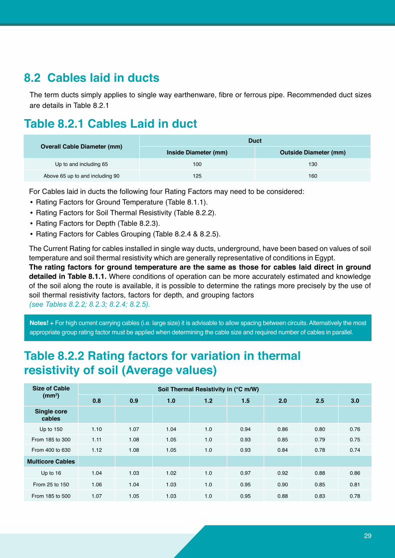
8.2Cableslaidinducts
OverallCableDiameter(mm)Duct
InsideDiameter(mm) OutsideDiameter(mm)
Up to and including 65 100 130
Above 65 up to and including 90 125 160
Thetermductssimplyappliestosinglewayearthenware,fibreorferrouspipe.Recommendedductsizesare details in Table 8.2.1
For Cables laid in ducts the following four Rating Factors may need to be considered:• Rating Factors for Ground Temperature (Table 8.1.1).• Rating Factors for Soil Thermal Resistivity (Table 8.2.2).• Rating Factors for Depth (Table 8.2.3).• Rating Factors for Cables Grouping (Table 8.2.4 & 8.2.5).
The Current Rating for cables installed in single way ducts, underground, have been based on values of soil temperature and soil thermal resistivity which are generally representative of conditions in Egypt.TheratingfactorsforgroundtemperaturearethesameasthoseforcableslaiddirectingrounddetailedinTable8.1.1. Where conditions of operation can be more accurately estimated and knowledge of the soil along the route is available, it is possible to determine the ratings more precisely by the use of soil thermal resistivity factors, factors for depth, and grouping factors(see Tables 8.2.2; 8.2.3; 8.2.4; 8.2.5).
Notes! + For high current carrying cables (i.e. large size) it is advisable to allow spacing between circuits. Alternatively the most appropriate group rating factor must be applied when determining the cable size and required number of cables in parallel.
Table8.2.2Ratingfactorsforvariationinthermalresistivityofsoil(Averagevalues)
Table8.2.1CablesLaidinduct
SizeofCable(mm2)
SoilThermalResistivityin(°Cm/W)
0.8 0.9 1.0 1.2 1.5 2.0 2.5 3.0Single core
cablesUp to 150 1.10 1.07 1.04 1.0 0.94 0.86 0.80 0.76
From 185 to 300 1.11 1.08 1.05 1.0 0.93 0.85 0.79 0.75
From 400 to 630 1.12 1.08 1.05 1.0 0.93 0.84 0.78 0.74
MulticoreCables
Up to 16 1.04 1.03 1.02 1.0 0.97 0.92 0.88 0.86
From 25 to 150 1.06 1.04 1.03 1.0 0.95 0.90 0.85 0.81
From 185 to 500 1.07 1.05 1.03 1.0 0.95 0.88 0.83 0.78
30
8.0CABLERATINGFACTORS
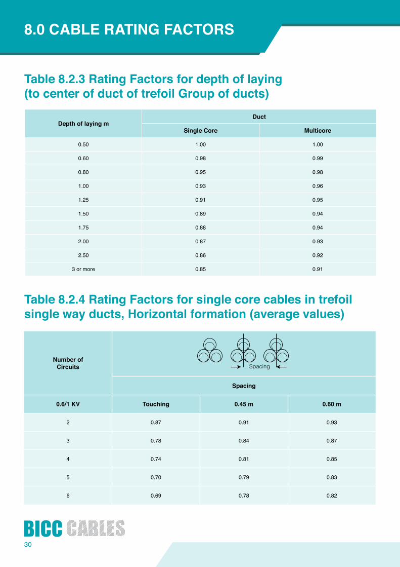
Table8.2.3RatingFactorsfordepthoflaying(tocenterofductoftrefoilGroupofducts)
Table8.2.4RatingFactorsforsinglecorecablesintrefoilsinglewayducts,Horizontalformation(averagevalues)
NumberofCircuits
Spacing
0.6/1 KV Touching 0.45m 0.60m
2 0.87 0.91 0.93
3 0.78 0.84 0.87
4 0.74 0.81 0.85
5 0.70 0.79 0.83
6 0.69 0.78 0.82
DepthoflayingmDuct
Single Core Multicore
0.50 1.00 1.00
0.60 0.98 0.99
0.80 0.95 0.98
1.00 0.93 0.96
1.25 0.91 0.95
1.50 0.89 0.94
1.75 0.88 0.94
2.00 0.87 0.93
2.50 0.86 0.92
3 or more 0.85 0.91
31
Table8.2.5RatingFactorsformulticorecablesinsinglewayducts,Horizontalformation(averagevalues)
Table8.3.1RatingFactorsforsinglecorecablesinair
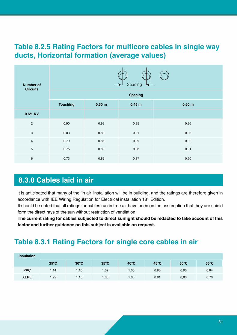
itisanticipatedthatmanyofthe‘inair’installationwillbeinbuilding,andtheratingsarethereforegiveninaccordance with IEE Wiring Regulation for Electrical installation 18th Edition.It should be noted that all ratings for cables run in free air have been on the assumption that they are shield form the direct rays of the sun without restriction of ventilation.Thecurrentratingforcablessubjectedtodirectsunlightshouldberedactedtotakeaccountofthisfactorandfurtherguidanceonthissubjectisavailableonrequest.
8.3.0 Cables laid in air
NumberofCircuits
Spacing
Touching 0.30m 0.45m 0.60m
0.6/1 KV
2 0.90 0.93 0.95 0.96
3 0.83 0.88 0.91 0.93
4 0.79 0.85 0.89 0.92
5 0.75 0.83 0.88 0.91
6 0.73 0.82 0.87 0.90
Insulation
25°C 30°C 35°C 40°C 45°C 50°C 55°C
PVC 1.14 1.10 1.02 1.00 0.96 0.90 0.84
XLPE 1.22 1.15 1.08 1.00 0.91 0,80 0.70
32
8.0CABLERATINGFACTORS
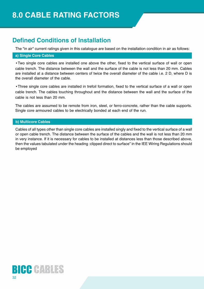
DefinedConditionsofInstallationThe "in air'' current ratings given in this catalogue are based on the installation condition in air as follows:
a)SingleCoreCables
•Twosinglecorecablesare installedoneabove theother,fixed to theverticalsurfaceofwalloropencable trench. The distance between the wall and the surface of the cable is not less than 20 mm. Cables are installed at a distance between centers of twice the overall diameter of the cable i.e. 2 D, where D is the overall diameter of the cable.
•Threesinglecorecablesareinstalledintrefoilformation,fixedtotheverticalsurfaceofawalloropencable trench. The cables touching throughout and the distance between the wall and the surface of the cable is not less than 20 mm.
The cables are assumed to be remote from iron, steel, or ferro-concrete, rather than the cable supports. Single core armoured cables to be electrically bonded at each end of the run.
b)MulticoreCables
Cables of all types otherthansinglecorecablesareinstalledsinglyandfixedtotheverticalsurfaceofawallor open cable trench. The distance between the surface of the cables and the wall is not less than 20 mm in very instance. If it is necessary for cables to be installed at distances less than those described above, then the values tabulated under the heading :clipped direct to surface” in the IEE Wiring Regulations should be employed
33
Ultravioletcablesresistantto heat, moisture, ozone& oil chemicals with highqualitymaterialsandrighttechnologies.
34
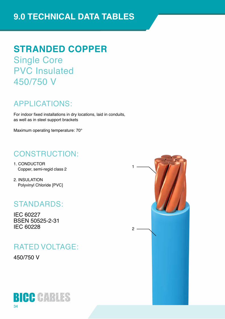
STRANDEDCOPPERSingle Core PVC Insulated 450/750 V
APPLICATIONS:
CONSTRUCTION:
STANDARDS:
RATED VOLTAGE:
INTRODUCTION9.0TECHNICALDATATABLES
Forindoorfixedinstallationsindrylocations,laidinconduits,as well as in steel support brackets
Maximumoperatingtemperature:70°
1
2
1. CONDUCTORCopper, semi-regid class 2
2. INSULATIONPolyvinyl Chloride [PVC]
IEC 60227BSEN 50525-2-31IEC 60228
450/750 V
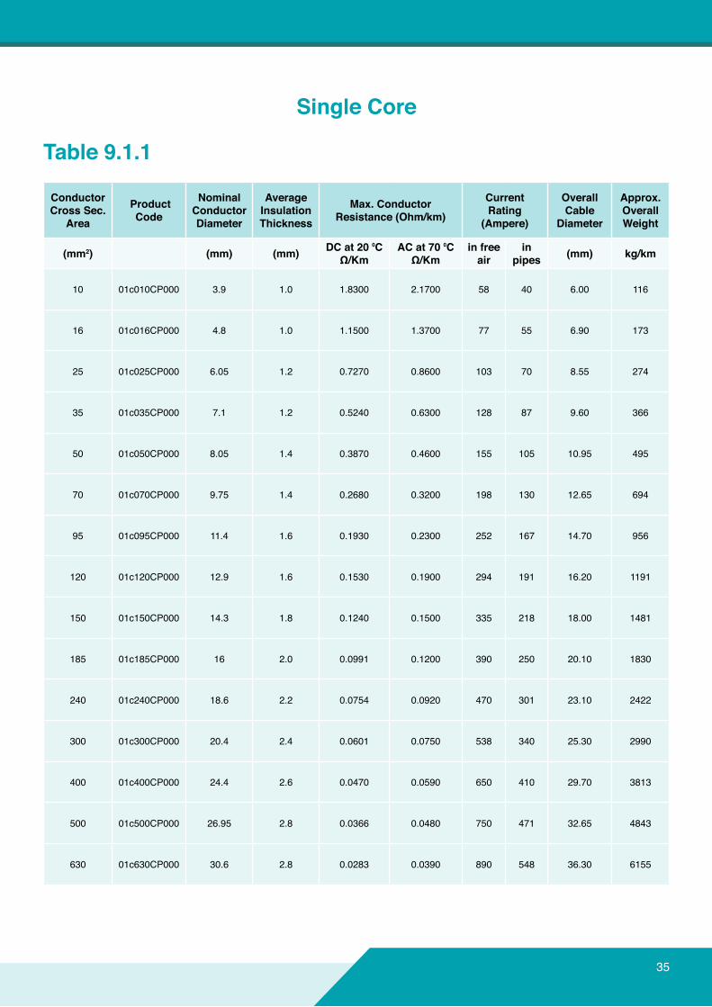
Table 9.1.1
Single Core
ConductorCross Sec.
Area
ProductCode
NominalConductorDiameter
AverageInsulationThickness
Max.ConductorResistance(Ohm/km)
CurrentRating
(Ampere)
Overall Cable
Diameter
Approx.Overall Weight
(mm2) (mm) (mm) DCat20⁰CΩ/Km
ACat70⁰CΩ/Km
infreeair
in pipes (mm) kg/km
10 01c010CP000 3.9 1.0 1.8300 2.1700 58 40 6.00 116
16 01c016CP000 4.8 1.0 1.1500 1.3700 77 55 6.90 173
25 01c025CP000 6.05 1.2 0.7270 0.8600 103 70 8.55 274
35 01c035CP000 7.1 1.2 0.5240 0.6300 128 87 9.60 366
50 01c050CP000 8.05 1.4 0.3870 0.4600 155 105 10.95 495
70 01c070CP000 9.75 1.4 0.2680 0.3200 198 130 12.65 694
95 01c095CP000 11.4 1.6 0.1930 0.2300 252 167 14.70 956
120 01c120CP000 12.9 1.6 0.1530 0.1900 294 191 16.20 1191
150 01c150CP000 14.3 1.8 0.1240 0.1500 335 218 18.00 1481
185 01c185CP000 16 2.0 0.0991 0.1200 390 250 20.10 1830
240 01c240CP000 18.6 2.2 0.0754 0.0920 470 301 23.10 2422
300 01c300CP000 20.4 2.4 0.0601 0.0750 538 340 25.30 2990
400 01c400CP000 24.4 2.6 0.0470 0.0590 650 410 29.70 3813
500 01c500CP000 26.95 2.8 0.0366 0.0480 750 471 32.65 4843
630 01c630CP000 30.6 2.8 0.0283 0.0390 890 548 36.30 6155
35

36
1
2
FLEXIBLECOPPERSingle Core PVC Insulated 450/750 V
APPLICATIONS:
CONSTRUCTION:
STANDARDS:
RATED VOLTAGE:
INTRODUCTION9.0TECHNICALDATATABLES
Forindoorfixedinstallationsindrylocations,whereparticularflexibilityis required. For electrical panels connection or for electrical apparatus. they can be laid in groups around steek sheet
Maximumoperatingtemperature:70°C
1. CONDUCTORCopper,flexibleclass5
2. INSULATIONPolyvinyl Chloride [PVC]
IEC 60227BSEN 50525-2-31IEC 60228
450/750 V
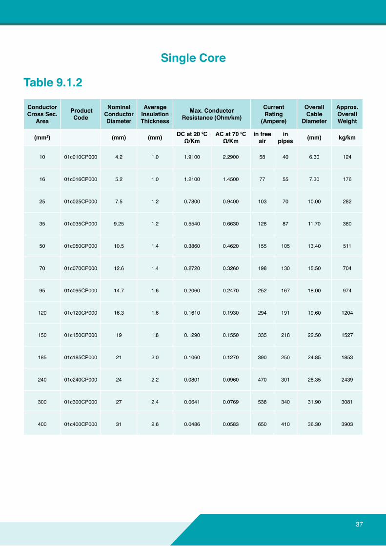
Table 9.1.2
Single Core
37
ConductorCross Sec.
Area
ProductCode
NominalConductorDiameter
AverageInsulationThickness
Max.ConductorResistance(Ohm/km)
CurrentRating
(Ampere)
Overall Cable
Diameter
Approx.Overall Weight
(mm2) (mm) (mm) DCat20⁰CΩ/Km
ACat70⁰CΩ/Km
infreeair
in pipes (mm) kg/km
10 01c010CP000 4.2 1.0 1.9100 2.2900 58 40 6.30 124
16 01c016CP000 5.2 1.0 1.2100 1.4500 77 55 7.30 176
25 01c025CP000 7.5 1.2 0.7800 0.9400 103 70 10.00 282
35 01c035CP000 9.25 1.2 0.5540 0.6630 128 87 11.70 380
50 01c050CP000 10.5 1.4 0.3860 0.4620 155 105 13.40 511
70 01c070CP000 12.6 1.4 0.2720 0.3260 198 130 15.50 704
95 01c095CP000 14.7 1.6 0.2060 0.2470 252 167 18.00 974
120 01c120CP000 16.3 1.6 0.1610 0.1930 294 191 19.60 1204
150 01c150CP000 19 1.8 0.1290 0.1550 335 218 22.50 1527
185 01c185CP000 21 2.0 0.1060 0.1270 390 250 24.85 1853
240 01c240CP000 24 2.2 0.0801 0.0960 470 301 28.35 2439
300 01c300CP000 27 2.4 0.0641 0.0769 538 340 31.90 3081
400 01c400CP000 31 2.6 0.0486 0.0583 650 410 36.30 3903

38
1
2
3
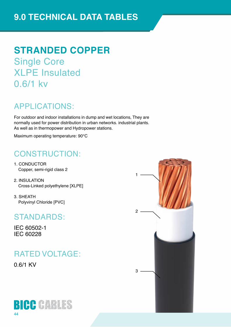
STRANDEDCOPPERSingle Core PVC Insulated 0.6/1 kv
APPLICATIONS:
CONSTRUCTION:
STANDARDS:
RATED VOLTAGE:
INTRODUCTION9.0TECHNICALDATATABLES
For outdoor and indoor installations in dump and wet locations, They are normally used for power distribution in urban networks. industrial plants. As well as in thermopower and hydropower stations
Maximumoperatingtemperature:70°C
1. CONDUCTORCopper, semi-rigid class 2
2. INSULATIONPolyvinyl Chloride [PVC]
3. SHEATH Polyvinyle Chlorid [PVC]
IEC 60502-1IEC 60228
0.6/1 KV
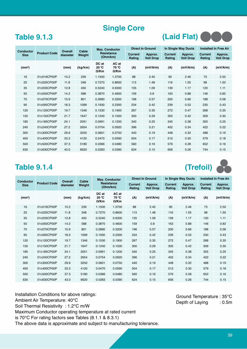
Table 9.1.3
Table 9.1.4
ConductorSize ProductCode Overall
diameterCable Weight
Max.ConductorResistance(Ohm/km)
DirectInGround InSingleWayDucts InstalledInFreeAir
CurrentRating
Approx.VoltDrop
CurrentRating
Approx.VoltDrop
CurrentRating
Approx.VoltDrop
(mm2) (mm) (kg/km)DCat20⁰CΩ/Km
ACat70⁰CΩ/Km
(A) (mV/A/m) (A) (mV/A/m) (A) (mV/A/m)
16 01c016CP00P 10.2 239 1.1500 1.3700 88 2.40 90 2.46 73 2.50
25 01c025CP00P 11.8 348 0.7270 0.8600 113 1.48 116 1.55 98 1.50
35 01c035CP00P 12.8 450 0.5240 0.6300 135 1.09 139 1.17 120 1.11
50 01c050CP00P 14.2 588 0.3870 0.4600 159 0.8 163 0.88 146 0.82
70 01c070CP00P 15.9 801 0.2680 0.3200 196 0.57 200 0.66 188 0.58
95 01c095CP00P 18.3 1099 0.1930 0.2300 234 0.42 239 0.53 230 0.43
120 01c120CP00P 19.7 1346 0.1530 0.1900 267 0.35 272 0.47 268 0.35
150 01c150CP00P 21.7 1647 0.1240 0.1500 300 0.29 305 0.42 309 0.30
185 01c185CP00P 24.1 2051 0.0991 0.1200 340 0.25 345 0.38 355 0.25
240 01c240CP00P 27.2 2654 0.0754 0.0920 396 0.21 402 0.34 422 0.22
300 01c300CP00P 29.6 3250 0.0601 0.0750 440 0.19 448 0.32 488 0.19
400 01c400CP00P 33.3 4120 0.0470 0.0590 504 0.17 512 0.30 579 0.18
500 01c500CP00P 37.3 5180 0.0366 0.0480 560 0.16 576 0.28 652 0.16
630 01c630CP00P 43.0 6620 0.0283 0.0390 624 0.15 656 0.26 744 0.15
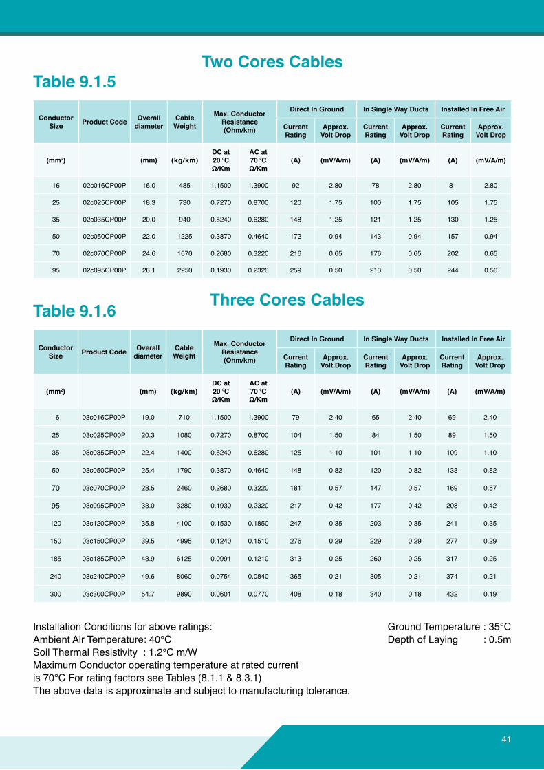
Installation Conditions for above ratings: Ambient Air Temperature: 40°C Soil Thermal Resistivity : 1.2°C m/W MaximumConductoroperatingtemperatureatratedcurrentis 70°C For rating factors see Tables (8.1.1 & 8.3.1)Theabovedataisapproximateandsubjecttomanufacturingtolerance.
Ground Temperature : 35°C Depth of Laying : 0.5m
Single Core(LaidFlat)
(Trefoil)
39
40
1
2
3
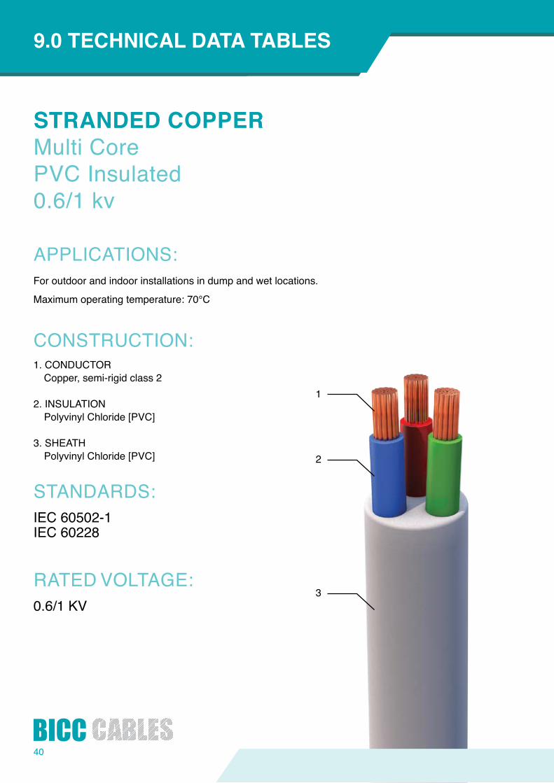
STRANDEDCOPPERMulti Core PVC Insulated 0.6/1 kv
APPLICATIONS:
CONSTRUCTION:
STANDARDS:
RATED VOLTAGE:
INTRODUCTION9.0TECHNICALDATATABLES
For outdoor and indoor installations in dump and wet locations.
Maximumoperatingtemperature:70°C
1. CONDUCTORCopper, semi-rigid class 2
2. INSULATIONPolyvinyl Chloride [PVC]
3. SHEATHPolyvinyl Chloride [PVC]
IEC 60502-1IEC 60228
0.6/1 KV
Installation Conditions for above ratings: Ambient Air Temperature: 40°C Soil Thermal Resistivity : 1.2°C m/W MaximumConductoroperatingtemperatureatratedcurrentis 70°C For rating factors see Tables (8.1.1 & 8.3.1)Theabovedataisapproximateandsubjecttomanufacturingtolerance.
Ground Temperature : 35°C Depth of Laying : 0.5m
Table 9.1.5
Table 9.1.6
ConductorSize ProductCode Overall
diameterCable Weight
Max.ConductorResistance(Ohm/km)
DirectInGround InSingleWayDucts InstalledInFreeAir
CurrentRating
Approx.VoltDrop
CurrentRating
Approx.VoltDrop
CurrentRating
Approx.VoltDrop
(mm2) (mm) (kg/km)DCat20⁰CΩ/Km
ACat70⁰CΩ/Km
(A) (mV/A/m) (A) (mV/A/m) (A) (mV/A/m)
16 02c016CP00P 16.0 485 1.1500 1.3900 92 2.80 78 2.80 81 2.80
25 02c025CP00P 18.3 730 0.7270 0.8700 120 1.75 100 1.75 105 1.75
35 02c035CP00P 20.0 940 0.5240 0.6280 148 1.25 121 1.25 130 1.25
50 02c050CP00P 22.0 1225 0.3870 0.4640 172 0.94 143 0.94 157 0.94
70 02c070CP00P 24.6 1670 0.2680 0.3220 216 0.65 176 0.65 202 0.65
95 02c095CP00P 28.1 2250 0.1930 0.2320 259 0.50 213 0.50 244 0.50
ConductorSize ProductCode Overall
diameterCable Weight
Max.ConductorResistance(Ohm/km)
DirectInGround InSingleWayDucts InstalledInFreeAir
CurrentRating
Approx.VoltDrop
CurrentRating
Approx.VoltDrop
CurrentRating
Approx.VoltDrop
(mm2) (mm) (kg/km)DCat20⁰CΩ/Km
ACat70⁰CΩ/Km
(A) (mV/A/m) (A) (mV/A/m) (A) (mV/A/m)
16 03c016CP00P 19.0 710 1.1500 1.3900 79 2.40 65 2.40 69 2.40
25 03c025CP00P 20.3 1080 0.7270 0.8700 104 1.50 84 1.50 89 1.50
35 03c035CP00P 22.4 1400 0.5240 0.6280 125 1.10 101 1.10 109 1.10
50 03c050CP00P 25.4 1790 0.3870 0.4640 148 0.82 120 0.82 133 0.82
70 03c070CP00P 28.5 2460 0.2680 0.3220 181 0.57 147 0.57 169 0.57
95 03c095CP00P 33.0 3280 0.1930 0.2320 217 0.42 177 0.42 208 0.42
120 03c120CP00P 35.8 4100 0.1530 0.1850 247 0.35 203 0.35 241 0.35
150 03c150CP00P 39.5 4995 0.1240 0.1510 276 0.29 229 0.29 277 0.29
185 03c185CP00P 43.9 6125 0.0991 0.1210 313 0.25 260 0.25 317 0.25
240 03c240CP00P 49.6 8060 0.0754 0.0840 365 0.21 305 0.21 374 0.21
300 03c300CP00P 54.7 9890 0.0601 0.0770 408 0.18 340 0.18 432 0.19
TwoCoresCables
Three Cores Cables
41
42
INTRODUCTION9.0TECHNICALDATATABLES
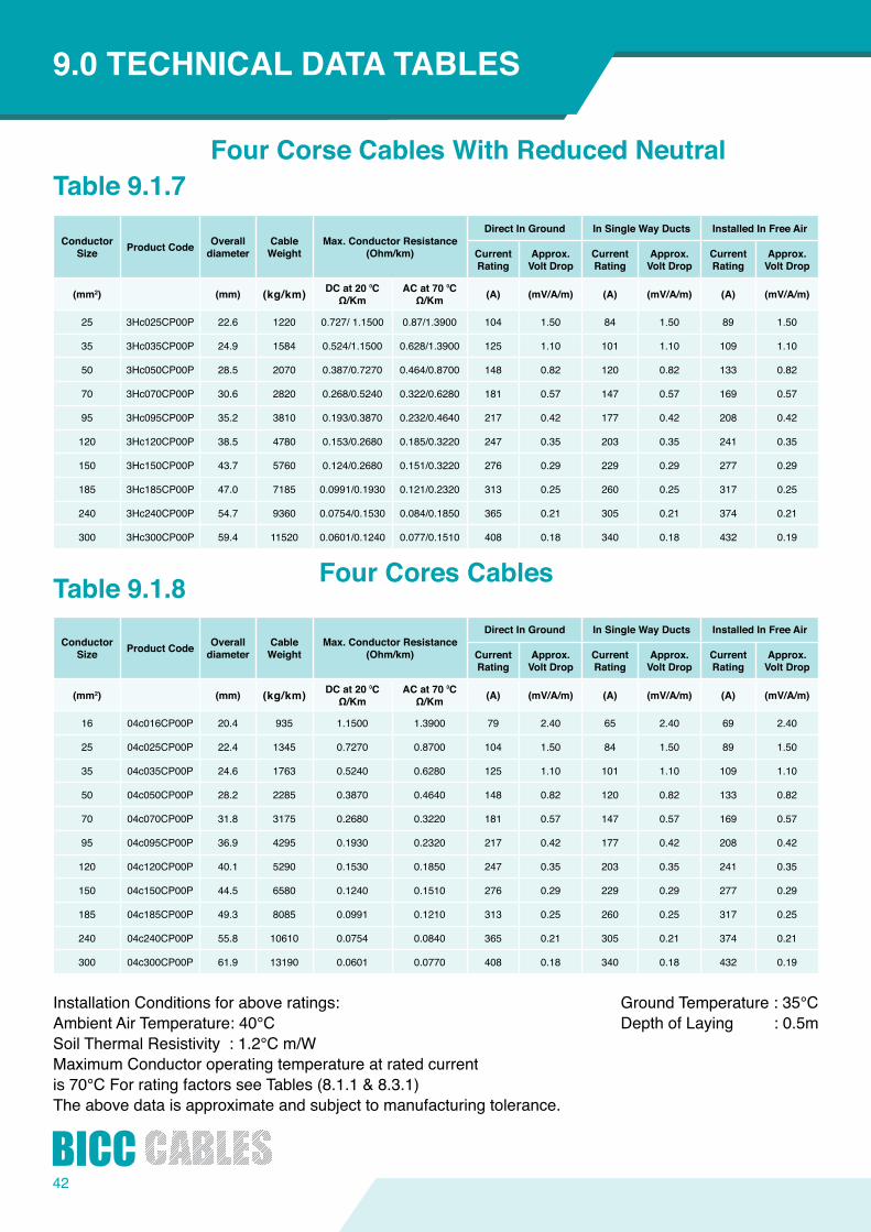
Installation Conditions for above ratings: Ambient Air Temperature: 40°C Soil Thermal Resistivity : 1.2°C m/W MaximumConductoroperatingtemperatureatratedcurrentis 70°C For rating factors see Tables (8.1.1 & 8.3.1)Theabovedataisapproximateandsubjecttomanufacturingtolerance.
Ground Temperature : 35°C Depth of Laying : 0.5m
Table 9.1.7
Table 9.1.8
ConductorSize ProductCode Overall
diameterCable Weight
Max.ConductorResistance(Ohm/km)
DirectInGround InSingleWayDucts InstalledInFreeAir
CurrentRating
Approx.VoltDrop
CurrentRating
Approx.VoltDrop
CurrentRating
Approx.VoltDrop
(mm2) (mm) (kg/km) DCat20⁰CΩ/Km
ACat70⁰CΩ/Km (A) (mV/A/m) (A) (mV/A/m) (A) (mV/A/m)
25 3Hc025CP00P 22.6 1220 0.727/ 1.1500 0.87/1.3900 104 1.50 84 1.50 89 1.50
35 3Hc035CP00P 24.9 1584 0.524/1.1500 0.628/1.3900 125 1.10 101 1.10 109 1.10
50 3Hc050CP00P 28.5 2070 0.387/0.7270 0.464/0.8700 148 0.82 120 0.82 133 0.82
70 3Hc070CP00P 30.6 2820 0.268/0.5240 0.322/0.6280 181 0.57 147 0.57 169 0.57
95 3Hc095CP00P 35.2 3810 0.193/0.3870 0.232/0.4640 217 0.42 177 0.42 208 0.42
120 3Hc120CP00P 38.5 4780 0.153/0.2680 0.185/0.3220 247 0.35 203 0.35 241 0.35
150 3Hc150CP00P 43.7 5760 0.124/0.2680 0.151/0.3220 276 0.29 229 0.29 277 0.29
185 3Hc185CP00P 47.0 7185 0.0991/0.1930 0.121/0.2320 313 0.25 260 0.25 317 0.25
240 3Hc240CP00P 54.7 9360 0.0754/0.1530 0.084/0.1850 365 0.21 305 0.21 374 0.21
300 3Hc300CP00P 59.4 11520 0.0601/0.1240 0.077/0.1510 408 0.18 340 0.18 432 0.19
ConductorSize ProductCode Overall
diameterCable Weight
Max.ConductorResistance(Ohm/km)
DirectInGround InSingleWayDucts InstalledInFreeAir
CurrentRating
Approx.VoltDrop
CurrentRating
Approx.VoltDrop
CurrentRating
Approx.VoltDrop
(mm2) (mm) (kg/km) DCat20⁰CΩ/Km
ACat70⁰CΩ/Km (A) (mV/A/m) (A) (mV/A/m) (A) (mV/A/m)
16 04c016CP00P 20.4 935 1.1500 1.3900 79 2.40 65 2.40 69 2.40
25 04c025CP00P 22.4 1345 0.7270 0.8700 104 1.50 84 1.50 89 1.50
35 04c035CP00P 24.6 1763 0.5240 0.6280 125 1.10 101 1.10 109 1.10
50 04c050CP00P 28.2 2285 0.3870 0.4640 148 0.82 120 0.82 133 0.82
70 04c070CP00P 31.8 3175 0.2680 0.3220 181 0.57 147 0.57 169 0.57
95 04c095CP00P 36.9 4295 0.1930 0.2320 217 0.42 177 0.42 208 0.42
120 04c120CP00P 40.1 5290 0.1530 0.1850 247 0.35 203 0.35 241 0.35
150 04c150CP00P 44.5 6580 0.1240 0.1510 276 0.29 229 0.29 277 0.29
185 04c185CP00P 49.3 8085 0.0991 0.1210 313 0.25 260 0.25 317 0.25
240 04c240CP00P 55.8 10610 0.0754 0.0840 365 0.21 305 0.21 374 0.21
300 04c300CP00P 61.9 13190 0.0601 0.0770 408 0.18 340 0.18 432 0.19
FourCorseCablesWithReducedNeutral
FourCoresCables
43
44
1
2
3
STRANDEDCOPPERSingle Core XLPE Insulated 0.6/1 kv
APPLICATIONS:
CONSTRUCTION:
STANDARDS:
RATED VOLTAGE:
INTRODUCTION9.0TECHNICALDATATABLES
For outdoor and indoor installations in dump and wet locations, They are normally used for power distribution in urban networks. industrial plants. As well as in thermopower and Hydropower stations.
Maximumoperatingtemperature:90°C
1. CONDUCTORCopper, semi-rigid class 2
2. INSULATIONCross-Linked polyethylene [XLPE]
3. SHEATHPolyvinyl Chloride [PVC]
IEC 60502-1IEC 60228
0.6/1 KV

Installation Conditions for above ratings:Ambient Air Temperature: 40°CSoil Thermal Resistivity : 1.2°C m/WMaximumConductoroperatingtemperatureatratedcurrentis 90°C For rating factors see Tables (8.1.1 & 8.1.3)Theabovedataisapproximateandsubjecttomanufacturingtolerance.
Ground Temperature : 35°C Depth of Laying : 0.5m
Table 9.1.9
Table 9.1.10
ConductorSize ProductCode Overall
diameterCable Weight
Max.ConductorResistance(Ohm/km)
DirectInGround InSingleWayDucts InstalledInFreeAir
CurrentRating
Approx.VoltDrop
CurrentRating
Approx.VoltDrop
CurrentRating
Approx.VoltDrop
(mm2) (mm) (kg/km)DCat20⁰CΩ/Km
ACat90⁰CΩ/Km
(A) (mV/A/m) (A) (mV/A/m) (A) (mV/A/m)
16 01c016CX00P 9.6 214 1.1500 1.4700 130 2.80 123 2.40 124 2.40
25 01c025CX00P 11.3 318 0.7270 0.9270 167 1 .76 158 1 .80 167 1.80
35 01c035CX00P 12.3 416 0.5240 0.6690 200 1.27 189 1.32 206 1.32
50 01c050CX00P 13.5 536 0.3870 0.4940 237 0.98 224 1.10 249 1.00
70 01c070CX00P 15.4 739 0.2680 0.3430 292 0.69 275 0.80 319 0.73
95 01c095CX00P 17.2 1009 0.1930 0.2480 344 0.53 323 0.65 388 0.56
120 01c120CX00P 18.9 1265 0.1530 0.1970 396 0.42 374 0.55 450 0.47
150 01c150CXOOP 20.9 1533 0.1240 0.1600 447 0.35 421 0.50 519 0.41
185 01c185CX00P 23.0 1884 0.0991 0.1290 507 0.30 482 0.45 592 0.36
240 01c240CX00P 26.0 2491 0.0754 0.0990 585 0.25 559 0.40 700 0.31
300 01c300CX00P 28.2 3052 0.0601 0.0810 662 0.22 636 0.37 806 0.29
400 01c400CX00P 31.9 3914 0.0470 0.0638 765 0.20 731 0.35 969 0.27
500 01c500CX00P 35.9 4976 0.0366 0.0517 860 0.19 826 0.32 1117 0.26
630 01c630CX00P 41.5 6347 0.0283 0.0425 989 0.17 946 0.30 1295 0.25
ConductorSize ProductCode Overall
diameterCable Weight
Max.ConductorResistance(Ohm/km)
DirectInGround InSingleWayDucts InstalledInFreeAir
CurrentRating
Approx.VoltDrop
CurrentRating
Approx.VoltDrop
CurrentRating
Approx.VoltDrop
(mm2) (mm) (kg/km)DCat20⁰CΩ/Km
ACat90⁰CΩ/Km
(A) (mV/A/m) (A) (mV/A/m) (A) (mV/A/m)
16 01c016CX00P 9.6 214 1.1500 1.4700 110 2.40 112 2.46 94 2.50
25 01c025CX00P 11.3 318 0.7270 0.9270 142 1.48 144 1.55 126 1.50
35 01c035CX00P 12.3 416 0.5240 0.6690 170 1.09 172 1.17 155 1.11
50 01c050CX00P 13.5 536 0.3870 0.4940 198 0.85 206 0.93 190 0.87
70 01c070CX00P 15.4 739 0.2680 0.3430 245 0.61 254 0.70 246 0.61
95 01c095CX00P 17.2 1009 0.1930 0.2480 288 0.45 297 0.56 300 0.45
120 01c120CX00P 18.9 1265 0.1530 0.1970 331 0.36 340 0.48 350 0.37
150 01c150CXOOP 20.9 1533 0.1240 0.1600 374 0.31 383 0.43 405 0.31
185 01c185CX00P 23.0 1884 0.0991 0.1290 421 0.26 430 0.39 465 0.26
240 01c240CX00P 26.0 2491 0.0754 0.0990 490 0.22 499 0.35 551 0.22
300 01c300CX00P 28.2 3052 0.0601 0.0810 559 0.19 559 0.32 638 0.20
400 01c400CX00P 31.9 3914 0.0470 0.0638 636 0.17 645 0.30 746 0.18
500 01c500CX00P 35.9 4976 0.0366 0.0517 722 0.16 731 0.28 852 0.16
630 01c630CX00P 41.5 6347 0.0283 0.0425 826 0.15 826 0.26 973 0.15
Single Core Cables
Single Core Cables
(LaidFlat)
(InTrefoil)
45

46
1
2
3
STRANDEDCOPPERMulti CoreXLPE Insulated0.6/1 kv
APPLICATIONS:
CONSTRUCTION:
STANDARDS:
RATED VOLTAGE:
INTRODUCTION9.0TECHNICALDATATABLES
Simi-rigidforuseinlowvoltagepowerdistributioninfixedindoorandoutdoor installations.
Maximumoperatingtemperature:90°C
1. CONDUCTORCopper, semi-rigid class 2
2. INSULATIONCross-Linked polyethylene [XLPE]
3. SHEATHPolyvinyl Chloride [PVC]
IEC 60502-1IEC 60228
0.6/1 KV
Installation Conditions for above ratings:Ambient Air Temperature: 40°CSoil Thermal Resistivity : 1.2°C m/WMaximumConductoroperatingtemperatureatratedcurrentis 90°C For rating factors see Tables (8.1.1 & 8.3.1)Theabovedataisapproximateandsubjecttomanufacturingtolerance.
Ground Temperature : 35°C Depth of Laying : 0.5m
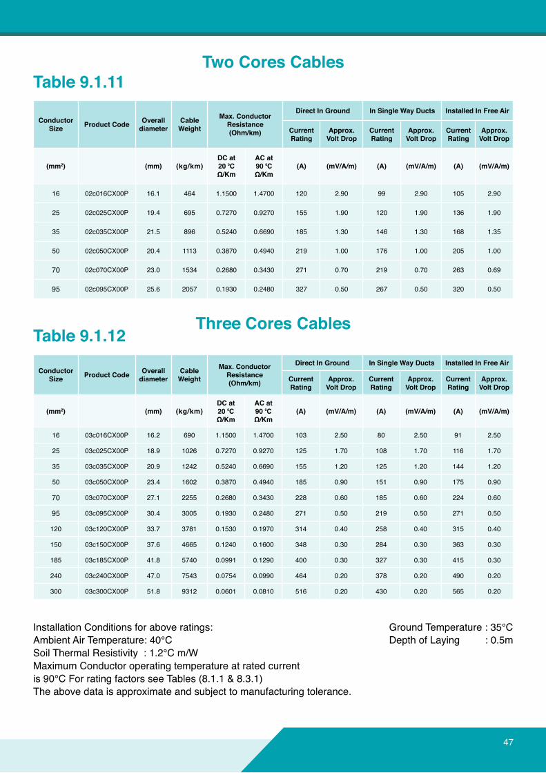
Table 9.1.11
Table 9.1.12
ConductorSize ProductCode Overall
diameterCable Weight
Max.ConductorResistance(Ohm/km)
DirectInGround InSingleWayDucts InstalledInFreeAir
CurrentRating
Approx.VoltDrop
CurrentRating
Approx.VoltDrop
CurrentRating
Approx.VoltDrop
(mm2) (mm) (kg/km)DCat20⁰CΩ/Km
ACat90⁰CΩ/Km
(A) (mV/A/m) (A) (mV/A/m) (A) (mV/A/m)
16 02c016CX00P 16.1 464 1.1500 1.4700 120 2.90 99 2.90 105 2.90
25 02c025CX00P 19.4 695 0.7270 0.9270 155 1.90 120 1.90 136 1.90
35 02c035CX00P 21.5 896 0.5240 0.6690 185 1.30 146 1.30 168 1.35
50 02c050CX00P 20.4 1113 0.3870 0.4940 219 1.00 176 1.00 205 1.00
70 02c070CX00P 23.0 1534 0.2680 0.3430 271 0.70 219 0.70 263 0.69
95 02c095CX00P 25.6 2057 0.1930 0.2480 327 0.50 267 0.50 320 0.50
ConductorSize ProductCode Overall
diameterCable Weight
Max.ConductorResistance(Ohm/km)
DirectInGround InSingleWayDucts InstalledInFreeAir
CurrentRating
Approx.VoltDrop
CurrentRating
Approx.VoltDrop
CurrentRating
Approx.VoltDrop
(mm2) (mm) (kg/km)DCat20⁰CΩ/Km
ACat90⁰CΩ/Km
(A) (mV/A/m) (A) (mV/A/m) (A) (mV/A/m)
16 03c016CX00P 16.2 690 1.1500 1.4700 103 2.50 80 2.50 91 2.50
25 03c025CX00P 18.9 1026 0.7270 0.9270 125 1.70 108 1.70 116 1.70
35 03c035CX00P 20.9 1242 0.5240 0.6690 155 1.20 125 1.20 144 1.20
50 03c050CX00P 23.4 1602 0.3870 0.4940 185 0.90 151 0.90 175 0.90
70 03c070CX00P 27.1 2255 0.2680 0.3430 228 0.60 185 0.60 224 0.60
95 03c095CX00P 30.4 3005 0.1930 0.2480 271 0.50 219 0.50 271 0.50
120 03c120CX00P 33.7 3781 0.1530 0.1970 314 0.40 258 0.40 315 0.40
150 03c150CX00P 37.6 4665 0.1240 0.1600 348 0.30 284 0.30 363 0.30
185 03c185CX00P 41.8 5740 0.0991 0.1290 400 0.30 327 0.30 415 0.30
240 03c240CX00P 47.0 7543 0.0754 0.0990 464 0.20 378 0.20 490 0.20
300 03c300CX00P 51.8 9312 0.0601 0.0810 516 0.20 430 0.20 565 0.20
TwoCoresCables
Three Cores Cables
47
48
INTRODUCTION9.0TECHNICALDATATABLES
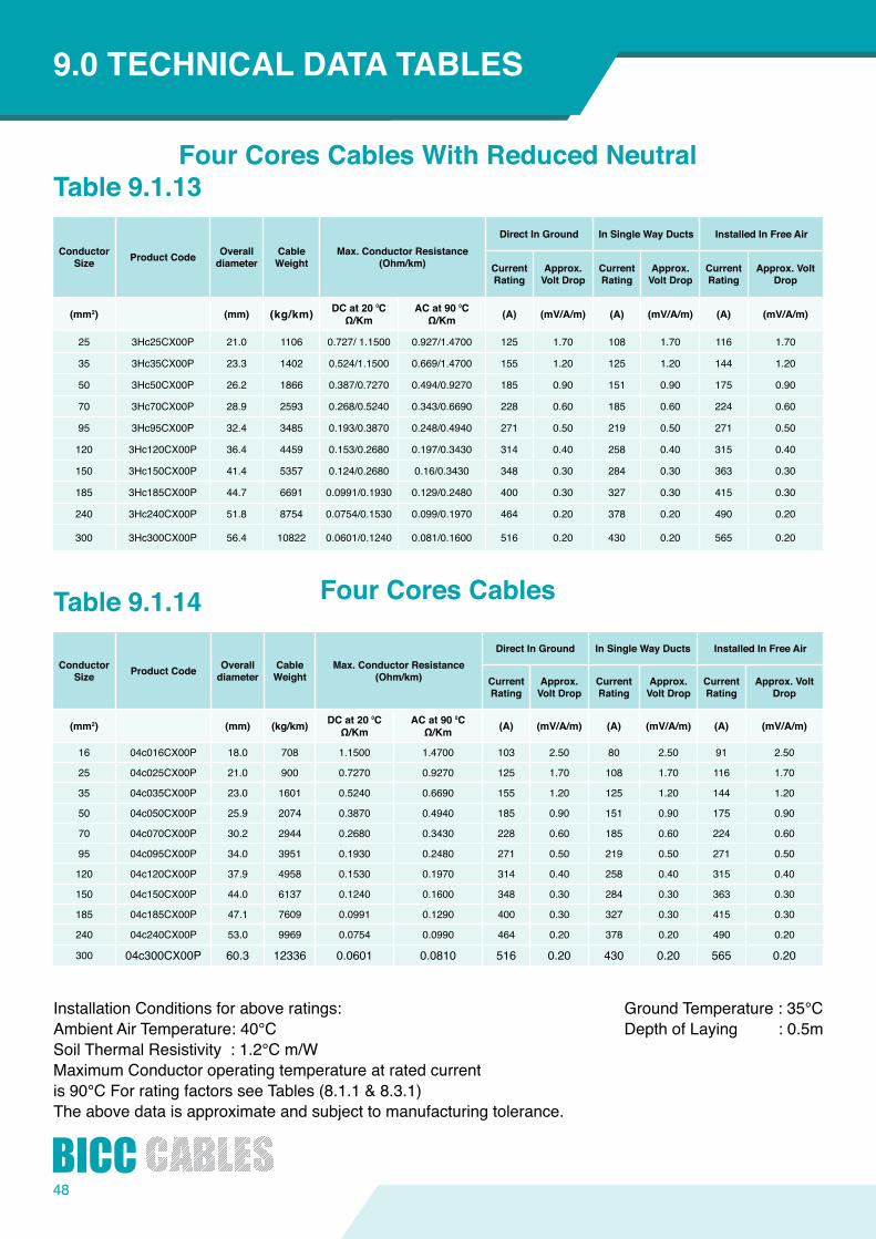
Installation Conditions for above ratings: Ambient Air Temperature: 40°C Soil Thermal Resistivity : 1.2°C m/W MaximumConductoroperatingtemperatureatratedcurrentis 90°C For rating factors see Tables (8.1.1 & 8.3.1)Theabovedataisapproximateandsubjecttomanufacturingtolerance.
Ground Temperature : 35°C Depth of Laying : 0.5m
Table 9.1.13
Table 9.1.14
ConductorSize ProductCode Overall
diameterCable Weight
Max.ConductorResistance(Ohm/km)
DirectInGround InSingleWayDucts InstalledInFreeAir
CurrentRating
Approx.VoltDrop
CurrentRating
Approx.VoltDrop
CurrentRating
Approx.VoltDrop
(mm2) (mm) (kg/km) DCat20⁰CΩ/Km
ACat90⁰CΩ/Km (A) (mV/A/m) (A) (mV/A/m) (A) (mV/A/m)
25 3Hc25CX00P 21.0 1106 0.727/ 1.1500 0.927/1.4700 125 1.70 108 1.70 116 1.70
35 3Hc35CX00P 23.3 1402 0.524/1.1500 0.669/1.4700 155 1.20 125 1.20 144 1.20
50 3Hc50CX00P 26.2 1866 0.387/0.7270 0.494/0.9270 185 0.90 151 0.90 175 0.90
70 3Hc70CX00P 28.9 2593 0.268/0.5240 0.343/0.6690 228 0.60 185 0.60 224 0.60
95 3Hc95CX00P 32.4 3485 0.193/0.3870 0.248/0.4940 271 0.50 219 0.50 271 0.50
120 3Hc120CX00P 36.4 4459 0.153/0.2680 0.197/0.3430 314 0.40 258 0.40 315 0.40
150 3Hc150CX00P 41.4 5357 0.124/0.2680 0.16/0.3430 348 0.30 284 0.30 363 0.30
185 3Hc185CX00P 44.7 6691 0.0991/0.1930 0.129/0.2480 400 0.30 327 0.30 415 0.30
240 3Hc240CX00P 51.8 8754 0.0754/0.1530 0.099/0.1970 464 0.20 378 0.20 490 0.20
300 3Hc300CX00P 56.4 10822 0.0601/0.1240 0.081/0.1600 516 0.20 430 0.20 565 0.20
ConductorSize ProductCode Overall
diameterCable Weight
Max.ConductorResistance(Ohm/km)
DirectInGround InSingleWayDucts InstalledInFreeAir
CurrentRating
Approx.VoltDrop
CurrentRating
Approx.VoltDrop
CurrentRating
Approx.VoltDrop
(mm2) (mm) (kg/km) DCat20⁰CΩ/Km
ACat90⁰CΩ/Km (A) (mV/A/m) (A) (mV/A/m) (A) (mV/A/m)
16 04c016CX00P 18.0 708 1.1500 1.4700 103 2.50 80 2.50 91 2.50
25 04c025CX00P 21.0 900 0.7270 0.9270 125 1.70 108 1.70 116 1.70
35 04c035CX00P 23.0 1601 0.5240 0.6690 155 1.20 125 1.20 144 1.20
50 04c050CX00P 25.9 2074 0.3870 0.4940 185 0.90 151 0.90 175 0.90
70 04c070CX00P 30.2 2944 0.2680 0.3430 228 0.60 185 0.60 224 0.60
95 04c095CX00P 34.0 3951 0.1930 0.2480 271 0.50 219 0.50 271 0.50
120 04c120CX00P 37.9 4958 0.1530 0.1970 314 0.40 258 0.40 315 0.40
150 04c150CX00P 44.0 6137 0.1240 0.1600 348 0.30 284 0.30 363 0.30
185 04c185CX00P 47.1 7609 0.0991 0.1290 400 0.30 327 0.30 415 0.30
240 04c240CX00P 53.0 9969 0.0754 0.0990 464 0.20 378 0.20 490 0.20
300 04c300CX00P 60.3 12336 0.0601 0.0810 516 0.20 430 0.20 565 0.20
FourCoresCablesWithReducedNeutral
FourCoresCables
49
50
1
2
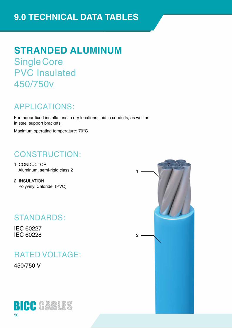
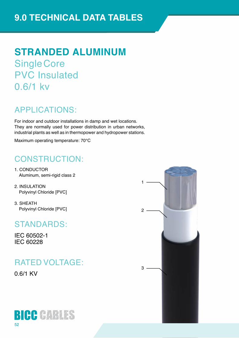
STRANDEDALUMINUMSingle CorePVC Insulated450/750v
APPLICATIONS:
CONSTRUCTION:
STANDARDS:
RATED VOLTAGE:
INTRODUCTION9.0TECHNICALDATATABLES
Forindoorfixedinstallationsindrylocations,laidinconduits,aswellasin steel support brackets.
Maximumoperatingtemperature:70°C
1. CONDUCTORAluminum, semi-rigid class 2
2. INSULATIONPolyvinyl Chloride (PVC)
IEC 60227IEC 60228
450/750 V
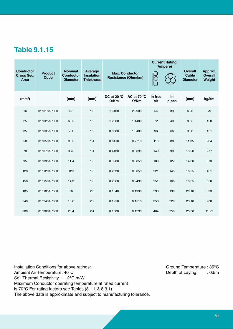
Installation Conditions for above ratings:Ambient Air Temperature: 40°CSoil Thermal Resistivity : 1.2°C m/WMaximumConductoroperatingtemperatureatratedcurrentis 70°C For rating factors see Tables (8.1.1 & 8.3.1)Theabovedataisapproximateandsubjecttomanufacturingtolerance.
Ground Temperature : 35°C Depth of Laying : 0.5m
Table 9.1.15
ConductorCross Sec.
Area
ProductCode
NominalConductorDiameter
AverageInsulationThickness
Max.ConductorResistance(Ohm/km)
CurrentRating(Ampere)
Overall Cable
Diameter
Approx.Overall Weight
(mm2) (mm) (mm) DCat20⁰CΩ/Km
ACat70⁰CΩ/Km
infreeair
inpipes (mm) kg/km
16 01c016AP000 4.8 1.0 1.9100 2.2900 54 39 6.90 79
25 01c025AP000 6.05 1.2 1.2000 1.4400 72 49 8.55 120
35 01c035AP000 7.1 1.2 0.8680 1.0400 96 66 9.60 151
50 01c050AP000 8.05 1.4 0.6410 0.7710 116 80 11.05 204
70 01c070AP000 9.75 1.4 0.4430 0.5330 149 99 13.20 277
95 01c095AP000 11.4 1.6 0.3200 0.3850 189 127 14.80 373
120 01c120AP000 129 1.6 0.2530 0.3050 221 145 16.25 451
150 01c150AP000 14.3 1.8 0.2060 0.2490 251 166 18.05 558
185 01c185AP000 16 2.0 0.1640 0.1990 293 190 20.10 693
240 01c240AP000 18.6 2.2 0.1250 0.1510 353 229 23.10 908
300 01c300AP000 20.4 2.4 0.1000 0.1230 404 258 25.30 11 22
51
52
1
2
3
STRANDEDALUMINUMSingle CorePVC Insulated0.6/1 kv
APPLICATIONS:
CONSTRUCTION:
STANDARDS:
RATED VOLTAGE:
INTRODUCTION9.0TECHNICALDATATABLES
For indoor and outdoor installations in damp and wet locations.They are normally used for power distribution in urban networks, industrial plants as well as in thermopower and hydropower stations.
Maximumoperatingtemperature:70°C
1. CONDUCTORAluminum, semi-rigid class 2
2. INSULATIONPolyvinyl Chloride [PVC]
3. SHEATHPolyvinyl Chloride [PVC]
IEC 60502-1IEC 60228
0.6/1 KV
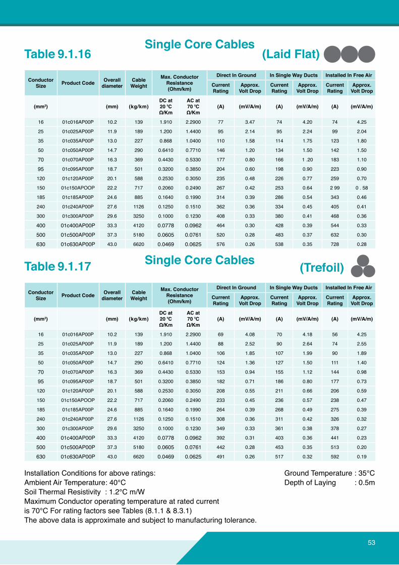
Installation Conditions for above ratings:Ambient Air Temperature: 40°CSoil Thermal Resistivity : 1.2°C m/WMaximumConductoroperatingtemperatureatratedcurrentis 70°C For rating factors see Tables (8.1.1 & 8.3.1)Theabovedataisapproximateandsubjecttomanufacturingtolerance.
Ground Temperature : 35°C Depth of Laying : 0.5m
Table 9.1.16
Table 9.1.17
(LaidFlat)
(Trefoil)
ConductorSize ProductCode Overall
diameterCable Weight
Max.ConductorResistance(Ohm/km)
DirectInGround InSingleWayDucts InstalledInFreeAir
CurrentRating
Approx.VoltDrop
CurrentRating
Approx.VoltDrop
CurrentRating
Approx.VoltDrop
(mm2) (mm) (kg/km)DCat20⁰CΩ/Km
ACat70⁰CΩ/Km
(A) (mV/A/m) (A) (mV/A/m) (A) (mV/A/m)
16 01c016AP00P 10.2 139 1.910 2.2900 77 3.47 74 4.20 74 4.25
25 01c025AP00P 11.9 189 1.200 1.4400 95 2.14 95 2.24 99 2.04
35 01c035AP00P 13.0 227 0.868 1.0400 110 1.58 114 1.75 123 1.80
50 01c050AP00P 14.7 290 0.6410 0.7710 146 1.20 134 1.50 142 1.50
70 01c070AP00P 16.3 369 0.4430 0.5330 177 0.80 166 1 .20 183 1.10
95 01c095AP00P 18.7 501 0.3200 0.3850 204 0.60 198 0.90 223 0.90
120 01c120AP00P 20.1 588 0.2530 0.3050 235 0.48 226 0.77 259 0.70
150 01c150APOOP 22.2 717 0.2060 0.2490 267 0.42 253 0.64 2 99 0 . 58
185 01c185AP00P 24.6 885 0.1640 0.1990 314 0.39 286 0.54 343 0.46
240 01c240AP00P 27.6 1126 0.1250 0.1510 362 0.36 334 0.45 405 0.41
300 01c300AP00P 29.6 3250 0.1000 0.1230 408 0.33 380 0.41 468 0.36
400 01c400AP00P 33.3 4120 0.0778 0.0962 464 0.30 428 0.39 544 0.33
500 01c500AP00P 37.3 5180 0.0605 0.0761 520 0.28 483 0.37 632 0.30
630 01c630AP00P 43.0 6620 0.0469 0.0625 576 0.26 538 0.35 728 0.28
ConductorSize ProductCode Overall
diameterCable Weight
Max.ConductorResistance(Ohm/km)
DirectInGround InSingleWayDucts InstalledInFreeAir
CurrentRating
Approx.VoltDrop
CurrentRating
Approx.VoltDrop
CurrentRating
Approx.VoltDrop
(mm2) (mm) (kg/km)DCat20⁰CΩ/Km
ACat70⁰CΩ/Km
(A) (mV/A/m) (A) (mV/A/m) (A) (mV/A/m)
16 01c016AP00P 10.2 139 1.910 2.2900 69 4.08 70 4.18 56 4.25
25 01c025AP00P 11.9 189 1.200 1.4400 88 2.52 90 2.64 74 2.55
35 01c035AP00P 13.0 227 0.868 1.0400 106 1.85 107 1.99 90 1.89
50 01c050AP00P 14.7 290 0.6410 0.7710 124 1.36 127 1.50 111 1.40
70 01c070AP00P 16.3 369 0.4430 0.5330 153 0.94 155 1.12 144 0.98
95 01c095AP00P 18.7 501 0.3200 0.3850 182 0.71 186 0.80 177 0.73
120 01c120AP00P 20.1 588 0.2530 0.3050 208 0.55 211 0.66 206 0.59
150 01c150APOOP 22.2 717 0.2060 0.2490 233 0.45 236 0.57 238 0.47
185 01c185AP00P 24.6 885 0.1640 0.1990 264 0.39 268 0.49 275 0.39
240 01c240AP00P 27.6 1126 0.1250 0.1510 308 0.36 311 0.42 326 0.32
300 01c300AP00P 29.6 3250 0.1000 0.1230 349 0.33 361 0.38 378 0.27
400 01c400AP00P 33.3 4120 0.0778 0.0962 392 0.31 403 0.36 441 0.23
500 01c500AP00P 37.3 5180 0.0605 0.0761 442 0.28 453 0.35 513 0.20
630 01c630AP00P 43.0 6620 0.0469 0.0625 491 0.26 517 0.32 592 0.19
Single Core Cables
Single Core Cables
53
54
1
2
3
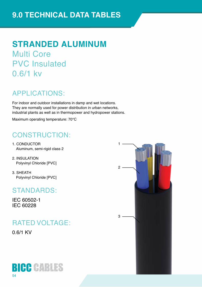
STRANDEDALUMINUMMulti CorePVC Insulated0.6/1 kv
APPLICATIONS:
CONSTRUCTION:
STANDARDS:
RATED VOLTAGE:
INTRODUCTION9.0TECHNICALDATATABLES
For indoor and outdoor installations in damp and wet locations.They are normally used for power distribution in urban networks,industrial plants as well as in thermopower and hydropower stations.
Maximumoperatingtemperature:70°C
1. CONDUCTORAluminum, semi-rigid class 2
2. INSULATIONPolyvinyl Chloride [PVC]
3. SHEATHPolyvinyl Chloride [PVC]
IEC 60502-1IEC 60228
0.6/1 KV
Installation Conditions for above ratings:Ambient Air Temperature: 40°CSoil Thermal Resistivity : 1.2°C m/WMaximumConductoroperatingtemperatureatratedcurrentis 70°C For rating factors see Tables (8.1.1 & 8.3.1)Theabovedataisapproximateandsubjecttomanufacturingtolerance.
Ground Temperature : 35°C Depth of Laying : 0.5m
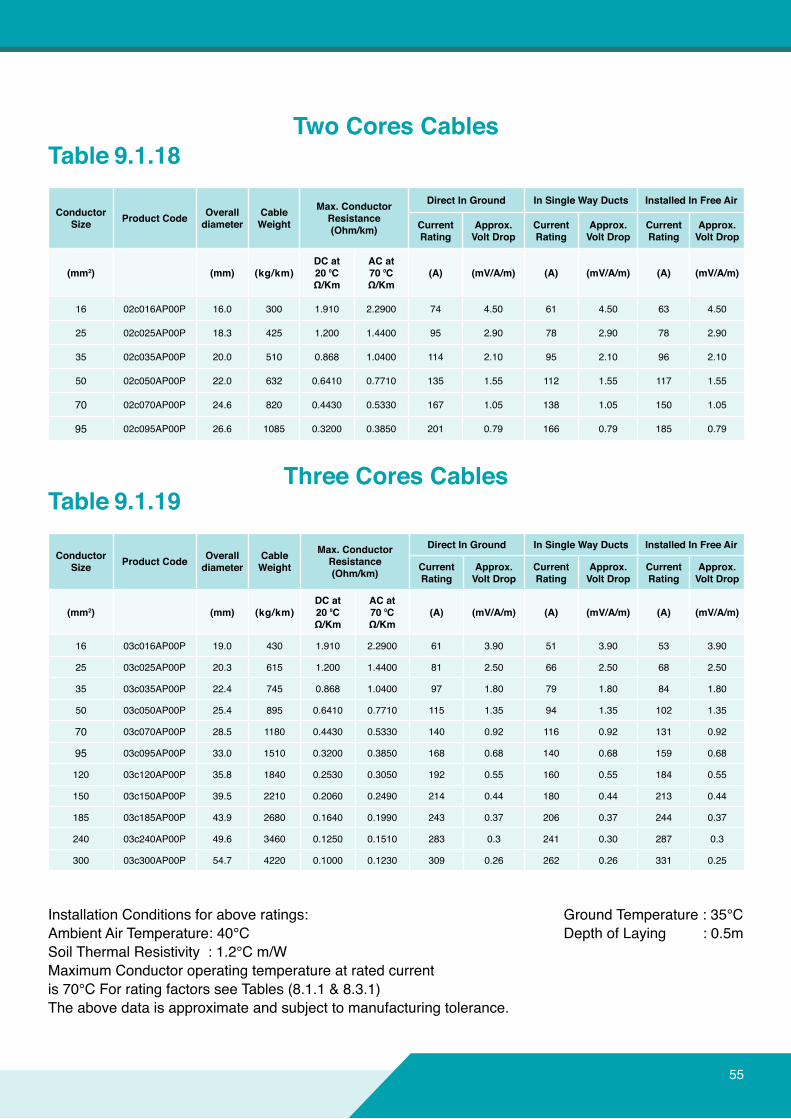
Table 9.1.19
ConductorSize ProductCode Overall
diameterCable Weight
Max.ConductorResistance(Ohm/km)
DirectInGround InSingleWayDucts InstalledInFreeAir
CurrentRating
Approx.VoltDrop
CurrentRating
Approx.VoltDrop
CurrentRating
Approx.VoltDrop
(mm2) (mm) (kg/km)DCat20⁰CΩ/Km
ACat70⁰CΩ/Km
(A) (mV/A/m) (A) (mV/A/m) (A) (mV/A/m)
16 03c016AP00P 19.0 430 1.910 2.2900 61 3.90 51 3.90 53 3.90
25 03c025AP00P 20.3 615 1.200 1.4400 81 2.50 66 2.50 68 2.50
35 03c035AP00P 22.4 745 0.868 1.0400 97 1.80 79 1.80 84 1.80
50 03c050AP00P 25.4 895 0.6410 0.7710 115 1.35 94 1.35 102 1.35
70 03c070AP00P 28.5 1180 0.4430 0.5330 140 0.92 116 0.92 131 0.92
95 03c095AP00P 33.0 1510 0.3200 0.3850 168 0.68 140 0.68 159 0.68
120 03c120AP00P 35.8 1840 0.2530 0.3050 192 0.55 160 0.55 184 0.55
150 03c150AP00P 39.5 2210 0.2060 0.2490 214 0.44 180 0.44 213 0.44
185 03c185AP00P 43.9 2680 0.1640 0.1990 243 0.37 206 0.37 244 0.37
240 03c240AP00P 49.6 3460 0.1250 0.1510 283 0.3 241 0.30 287 0.3
300 03c300AP00P 54.7 4220 0.1000 0.1230 309 0.26 262 0.26 331 0.25
Table 9.1.18
ConductorSize ProductCode Overall
diameterCable Weight
Max.ConductorResistance(Ohm/km)
DirectInGround InSingleWayDucts InstalledInFreeAir
CurrentRating
Approx.VoltDrop
CurrentRating
Approx.VoltDrop
CurrentRating
Approx.VoltDrop
(mm2) (mm) (kg/km)DCat20⁰CΩ/Km
ACat70⁰CΩ/Km
(A) (mV/A/m) (A) (mV/A/m) (A) (mV/A/m)
16 02c016AP00P 16.0 300 1.910 2.2900 74 4.50 61 4.50 63 4.50
25 02c025AP00P 18.3 425 1.200 1.4400 95 2.90 78 2.90 78 2.90
35 02c035AP00P 20.0 510 0.868 1.0400 114 2.10 95 2.10 96 2.10
50 02c050AP00P 22.0 632 0.6410 0.7710 135 1.55 112 1.55 117 1.55
70 02c070AP00P 24.6 820 0.4430 0.5330 167 1.05 138 1.05 150 1.05
95 02c095AP00P 26.6 1085 0.3200 0.3850 201 0.79 166 0.79 185 0.79
TwoCoresCables
Three Cores Cables
55

56
INTRODUCTION9.0TECHNICALDATATABLES
Installation Conditions for above ratings: Ambient Air Temperature: 40°C Soil Thermal Resistivity : 1.2°C m/W MaximumConductoroperatingtemperatureatratedcurrentis 70°C For rating factors see Tables (8.1.1 & 8.3.1)Theabovedataisapproximateandsubjecttomanufacturingtolerance.
Ground Temperature : 35°C Depth of Laying : 0.5m
Table 9.1.20
Table 9.1.20
ConductorSize ProductCode Overall
diameterCable Weight
Max.ConductorResistance(Ohm/km)
DirectInGround InSingleWayDucts InstalledInFreeAir
CurrentRating
Approx.VoltDrop
CurrentRating
Approx.VoltDrop
CurrentRating
Approx.VoltDrop
(mm2) (mm) (kg/km) DCat20⁰CΩ/Km
ACat70⁰CΩ/Km (A) (mV/A/m) (A) (mV/A/m) (A) (mV/A/m)
25 3Hc25AP00P 22.6 666 1.200/1.1910 1.440/2.290 81 2.50 51 2.50 68 2.50
35 3Hc35AP00P 24.9 815 0.868/1.9100 1.0430/2.2900 97 1.80 66 1.80 85 1.80
50 3Hc50AP00P 28.5 1032 0.641/1.2000 0.7710/1.4400 115 1.35 79 1.35 103 1.35
70 3Hc70AP00P 30.6 1320 0.443/0.8680 0.5330/1.0400 140 0.92 94 0.92 131 0.92
95 3Hc95AP00P 35.2 1740 0.32/0.6410 0.3850/0.7710 168 0.68 116 0.68 160 0.68
120 3Hc120AP00P 38.5 2110 0.253/0.4430 0.3050/0.5330 192 0.55 140 0.55 185 0.55
150 3Hc150AP00P 43.7 2550 0.206/0.4430 0.2490/0.5330 214 0.44 160 0.44 214 0.44
185 3Hc185AP00P 47.0 3145 0.164/0.3200 0.1990/0.3850 243 0.37 180 0.37 246 0.37
240 3Hc240AP00P 54.7 4025 0.125/0.2530 0.1510/0.3050 283 0.3 206 0.30 287 0.3
300 3Hc300AP00P 59.4 4920 0.1/0.2060 0.1230/0.2490 309 0.26 262 0.26 331 0.25
ConductorSize ProductCode Overall
diameterCable Weight
Max.ConductorResistance(Ohm/km)
DirectInGround InSingleWayDucts InstalledInFreeAir
CurrentRating
Approx.VoltDrop
CurrentRating
Approx.VoltDrop
CurrentRating
Approx.VoltDrop
(mm2) (mm) (kg/km) DCat20⁰CΩ/Km
ACat70⁰CΩ/Km (A) (mV/A/m) (A) (mV/A/m) (A) (mV/A/m)
16 04c016AP00P 20.4 553 1.910 2.2900 61 3.90 51 3.90 54 3.90
25 04c025AP00P 22.4 713 1.200 1.4400 81 2.50 66 2.50 68 2.50
35 04c035AP00P 24.6 892 0.868 1.0400 97 1.80 79 1.80 85 1.80
50 04c050AP00P 28.2 1100 0.6410 0.7710 115 1.35 94 1.35 103 1.35
70 04c070AP00P 31.8 1470 0.4430 0.5330 140 0.92 116 0.92 131 0.92
95 04c095AP00P 36.9 1939 0.3200 0.3850 168 0.68 140 0.68 160 0.68
120 04c120AP00P 40.1 2300 0.2530 0.3050 192 0.55 160 0.55 185 0.55
150 04c150AP00P 44.5 2858 0.2060 0.2490 214 0.44 180 0.44 214 0.44
185 04c185AP00P 49.3 3491 0.1640 0.1990 243 0.37 206 0.37 246 0.37
240 04c240AP00P 55.8 4489 0.1250 0.1510 283 0.3 241 0.30 287 0.3
300 04c300AP00P 61.9 5622 0.1000 0.1230 309 0.26 262 0.26 331 0.25
FourCoresCablesWithReducedNeutral
FourCoresCables
57
Ourproductsaredesigned&constructedtobehazardfreeundertheprescribedconditionsofuse.
Tolightupasafelife
58
1
2
3
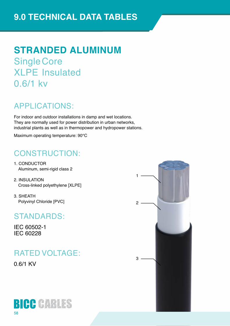
STRANDEDALUMINUMSingle CoreXLPE Insulated0.6/1 kv
APPLICATIONS:
CONSTRUCTION:
STANDARDS:
RATED VOLTAGE:
INTRODUCTION9.0TECHNICALDATATABLES
For indoor and outdoor installations in damp and wet locations.They are normally used for power distribution in urban networks,industrial plants as well as in thermopower and hydropower stations.
Maximumoperatingtemperature:90°C
1. CONDUCTORAluminum, semi-rigid class 2
2. INSULATIONCross-linked polyethylene [XLPE]
3. SHEATHPolyvinyl Chloride [PVC]
IEC 60502-1IEC 60228
0.6/1 KV

Installation Conditions for above ratings:Ambient Air Temperature: 40°CSoil Thermal Resistivity : 1.2°C m/WMaximumConductoroperatingtemperatureatratedcurrentis 90°C For rating factors see Tables (8.1.1 & 8.3.1)Theabovedataisapproximateandsubjecttomanufacturingtolerance.
Ground Temperature : 35°C Depth of Laying : 0.5m
Table 9.1.22
Table 9.1.23
ConductorSize ProductCode Overall
diameterCable Weight
Max.ConductorResistance(Ohm/km)
DirectInGround InSingleWayDucts InstalledInFreeAir
CurrentRating
Approx.VoltDrop
CurrentRating
Approx.VoltDrop
CurrentRating
Approx.VoltDrop
(mm2) (mm) (kg/km)DCat20⁰CΩ/Km
ACat90⁰CΩ/Km
(A) (mV/A/m) (A) (mV/A/m) (A) (mV/A/m)
16 01c016AX00P 9.6 119 1.910 2.4500 95 3.47 93 4.20 101 4.25
25 01c025AX00P 11.3 165 1.200 1.5400 118 2.14 119 2.24 135 2.04
35 01c035AX00P 12.3 201 0.868 1.1130 137 1.65 141 1.80 167 1.85
50 01c050AX00P 13.6 248 0.6410 0.8220 181 1.55 168 1.70 191 1.68
70 01c070AX00P 15.4 328 0.4430 0.5690 219 1.10 206 1.20 247 1.15
95 01c095AX00P 17.3 435 0.3200 0.4110 262 0.82 245 0.91 302 0.94
120 01c120AX00P 19.0 522 0.2530 0.3250 301 0.66 284 0.76 352 0.70
150 01c150AX00P 21.0 640 0.2060 0.2650 335 0.55 314 0.66 408 0.58
185 01c185AX00P 23.0 777 0.1640 0.2120 378 0.45 353 0.57 469 0.49
240 01c240AX00P 26.0 989 0.1250 0.1630 439 0.36 417 0.49 556 0.41
300 01c300AX00P 28.2 1202 0.1000 0.1310 499 0.31 473 0.45 644 0.36
400 01c400AX00P 31.9 1517 0.0778 0.1000 568 0.29 533 0.43 726 0.33
500 01c500AX00P 35.9 1901 0.0605 0.0870 636 0.28 602 0.41 844 0.30
630 01c630AX00P 42.0 2444 0.0469 0.0620 705 0.26 671 0.37 963 0.28
ConductorSize ProductCode Overall
diameterCable Weight
Max.ConductorResistance(Ohm/km)
DirectInGround InSingleWayDucts InstalledInFreeAir
CurrentRating
Approx.VoltDrop
CurrentRating
Approx.VoltDrop
CurrentRating
Approx.VoltDrop
(mm2) (mm) (kg/km)DCat20⁰CΩ/Km
ACat90⁰CΩ/Km
(A) (mV/A/m) (A) (mV/A/m) (A) (mV/A/m)
16 01c016AX00P 9.6 119 1.910 2.4500 83 4.08 85 4.18 73 4.25
25 01c025AX00P 11.3 165 1.200 1.5400 107 2.52 109 2.64 96 2.55
35 01c035AX00P 12.3 201 0.868 1.1130 127 1.85 130 1.99 118 1.89
50 01c050AX00P 13.6 248 0.6410 0.8220 151 1.40 155 1.50 145 1.45
70 01c070AX00P 15.4 328 0.4430 0.5690 185 0.98 189 1.10 187 0.98
95 01c095AX00P 17.3 435 0.3200 0.4110 219 0.71 224 0.79 230 0.73
120 01c120AX00P 19.0 522 0.2530 0.3250 254 0.57 258 0.66 269 0.59
150 01c150AX00P 21.0 640 0.2060 0.2650 280 0.47 288 0.57 312 0.47
185 01c185AX00P 23.0 777 0.1640 0.2120 318 0.39 323 0.49 359 0.39
240 01c240AX00P 26.0 989 0.1250 0.1630 370 0.31 378 0.42 429 0.32
300 01c300AX00P 28.2 1202 0.1000 0.1310 421 0.26 439 0.39 495 0.27
400 01c400AX00P 31.9 1517 0.0778 0.1000 473 0.22 490 0.38 581 0.23
500 01c500AX00P 35.9 1901 0.0605 0.0870 533 0.20 550 0.35 676 0.20
630 01c630AX00P 42.0 2444 0.0469 0.0620 593 0.19 628 0.32 773 0.19
(LaidFlat)
(InTrefoil)
Single Core Cables
Single Core Cables
59
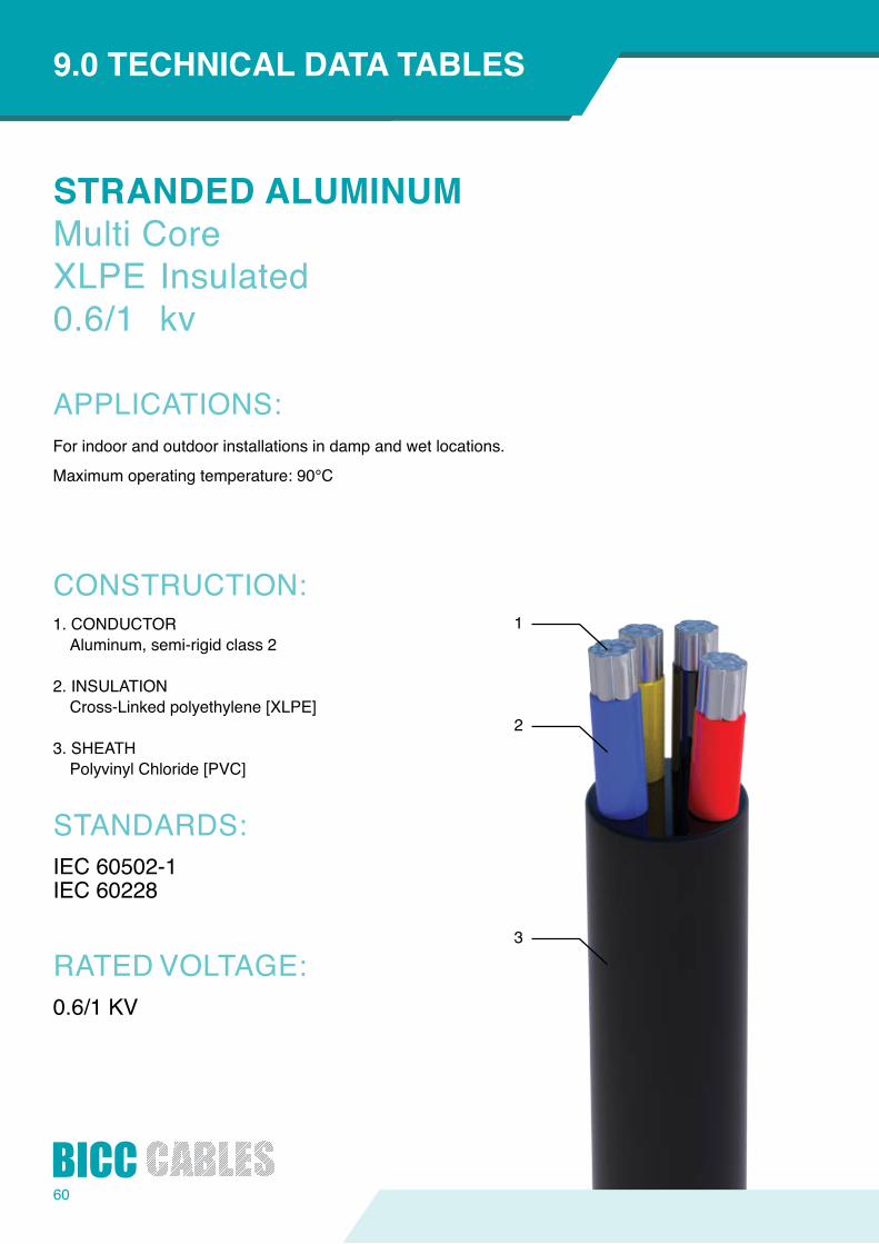
60
1
2
3
STRANDEDALUMINUMMulti CoreXLPE Insulated0.6/1 kv
APPLICATIONS:
CONSTRUCTION:
STANDARDS:
RATED VOLTAGE:
INTRODUCTION9.0TECHNICALDATATABLES
For indoor and outdoor installations in damp and wet locations.
Maximumoperatingtemperature:90°C
1. CONDUCTORAluminum, semi-rigid class 2
2. INSULATIONCross-Linked polyethylene [XLPE]
3. SHEATHPolyvinyl Chloride [PVC]
IEC 60502-1IEC 60228
0.6/1 KV
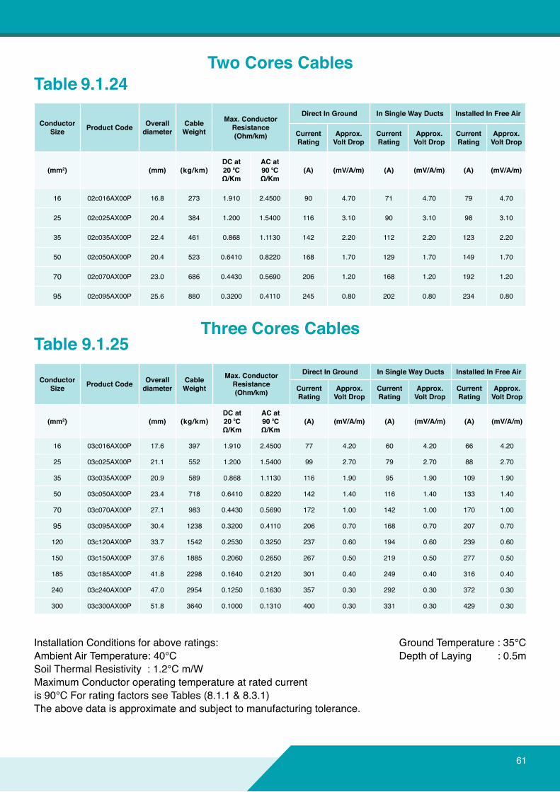
Installation Conditions for above ratings:Ambient Air Temperature: 40°CSoil Thermal Resistivity : 1.2°C m/WMaximumConductoroperatingtemperatureatratedcurrentis 90°C For rating factors see Tables (8.1.1 & 8.3.1)Theabovedataisapproximateandsubjecttomanufacturingtolerance.
Ground Temperature : 35°C Depth of Laying : 0.5m
Table 9.1.24
Table 9.1.25
ConductorSize ProductCode Overall
diameterCable Weight
Max.ConductorResistance(Ohm/km)
DirectInGround InSingleWayDucts InstalledInFreeAir
CurrentRating
Approx.VoltDrop
CurrentRating
Approx.VoltDrop
CurrentRating
Approx.VoltDrop
(mm2) (mm) (kg/km)DCat20⁰CΩ/Km
ACat90⁰CΩ/Km
(A) (mV/A/m) (A) (mV/A/m) (A) (mV/A/m)
16 02c016AX00P 16.8 273 1.910 2.4500 90 4.70 71 4.70 79 4.70
25 02c025AX00P 20.4 384 1.200 1.5400 116 3.10 90 3.10 98 3.10
35 02c035AX00P 22.4 461 0.868 1.1130 142 2.20 112 2.20 123 2.20
50 02c050AX00P 20.4 523 0.6410 0.8220 168 1.70 129 1.70 149 1.70
70 02c070AX00P 23.0 686 0.4430 0.5690 206 1.20 168 1.20 192 1.20
95 02c095AX00P 25.6 880 0.3200 0.4110 245 0.80 202 0.80 234 0.80
ConductorSize ProductCode Overall
diameterCable Weight
Max.ConductorResistance(Ohm/km)
DirectInGround InSingleWayDucts InstalledInFreeAir
CurrentRating
Approx.VoltDrop
CurrentRating
Approx.VoltDrop
CurrentRating
Approx.VoltDrop
(mm2) (mm) (kg/km)DCat20⁰CΩ/Km
ACat90⁰CΩ/Km
(A) (mV/A/m) (A) (mV/A/m) (A) (mV/A/m)
16 03c016AX00P 17.6 397 1.910 2.4500 77 4.20 60 4.20 66 4.20
25 03c025AX00P 21.1 552 1.200 1.5400 99 2.70 79 2.70 88 2.70
35 03c035AX00P 20.9 589 0.868 1.1130 116 1.90 95 1.90 109 1.90
50 03c050AX00P 23.4 718 0.6410 0.8220 142 1.40 116 1.40 133 1.40
70 03c070AX00P 27.1 983 0.4430 0.5690 172 1.00 142 1.00 170 1.00
95 03c095AX00P 30.4 1238 0.3200 0.4110 206 0.70 168 0.70 207 0.70
120 03c120AX00P 33.7 1542 0.2530 0.3250 237 0.60 194 0.60 239 0.60
150 03c150AX00P 37.6 1885 0.2060 0.2650 267 0.50 219 0.50 277 0.50
185 03c185AX00P 41.8 2298 0.1640 0.2120 301 0.40 249 0.40 316 0.40
240 03c240AX00P 47.0 2954 0.1250 0.1630 357 0.30 292 0.30 372 0.30
300 03c300AX00P 51.8 3640 0.1000 0.1310 400 0.30 331 0.30 429 0.30
TwoCoresCables
Three Cores Cables
61
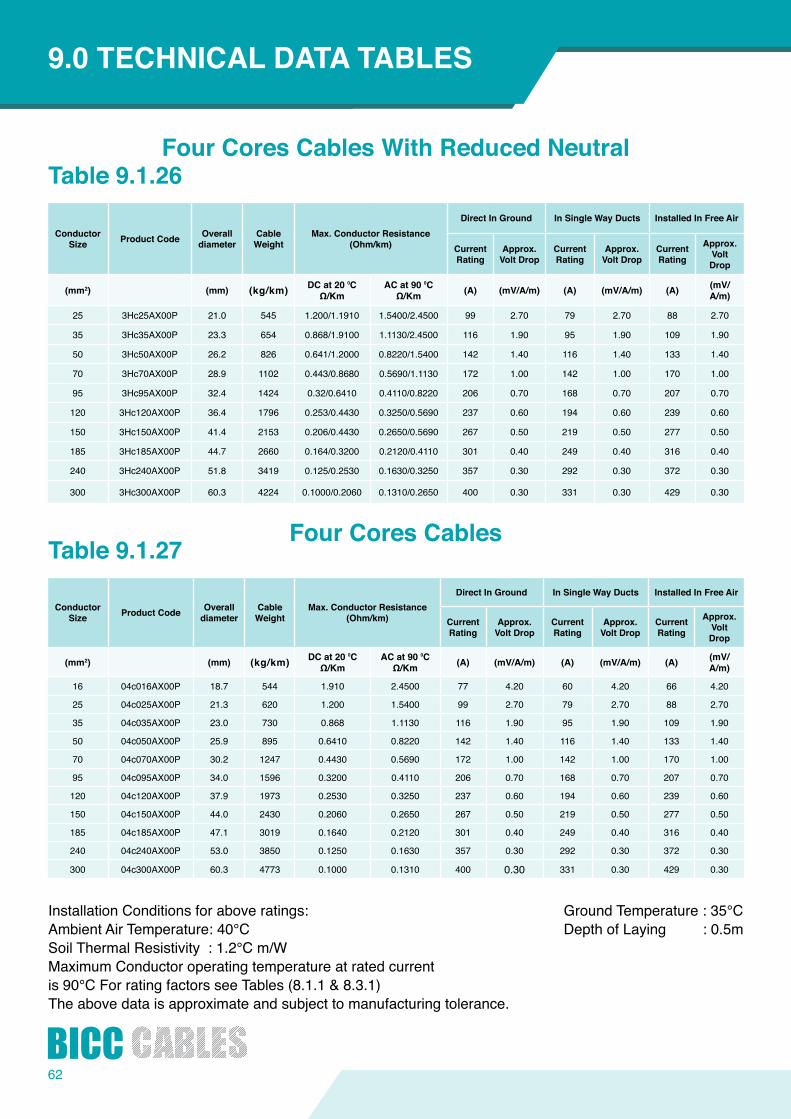
62
INTRODUCTION9.0TECHNICALDATATABLES
Installation Conditions for above ratings: Ambient Air Temperature: 40°C Soil Thermal Resistivity : 1.2°C m/W MaximumConductoroperatingtemperatureatratedcurrentis 90°C For rating factors see Tables (8.1.1 & 8.3.1)Theabovedataisapproximateandsubjecttomanufacturingtolerance.
Ground Temperature : 35°C Depth of Laying : 0.5m
Table 9.1.26
Table 9.1.27
ConductorSize ProductCode Overall
diameterCable Weight
Max.ConductorResistance(Ohm/km)
DirectInGround InSingleWayDucts InstalledInFreeAir
CurrentRating
Approx.VoltDrop
CurrentRating
Approx.VoltDrop
CurrentRating
Approx.VoltDrop
(mm2) (mm) (kg/km) DCat20⁰CΩ/Km
ACat90⁰CΩ/Km (A) (mV/A/m) (A) (mV/A/m) (A) (mV/
A/m)
25 3Hc25AX00P 21.0 545 1.200/1.1910 1.5400/2.4500 99 2.70 79 2.70 88 2.70
35 3Hc35AX00P 23.3 654 0.868/1.9100 1.1130/2.4500 116 1.90 95 1.90 109 1.90
50 3Hc50AX00P 26.2 826 0.641/1.2000 0.8220/1.5400 142 1.40 116 1.40 133 1.40
70 3Hc70AX00P 28.9 1102 0.443/0.8680 0.5690/1.1130 172 1.00 142 1.00 170 1.00
95 3Hc95AX00P 32.4 1424 0.32/0.6410 0.4110/0.8220 206 0.70 168 0.70 207 0.70
120 3Hc120AX00P 36.4 1796 0.253/0.4430 0.3250/0.5690 237 0.60 194 0.60 239 0.60
150 3Hc150AX00P 41.4 2153 0.206/0.4430 0.2650/0.5690 267 0.50 219 0.50 277 0.50
185 3Hc185AX00P 44.7 2660 0.164/0.3200 0.2120/0.4110 301 0.40 249 0.40 316 0.40
240 3Hc240AX00P 51.8 3419 0.125/0.2530 0.1630/0.3250 357 0.30 292 0.30 372 0.30
300 3Hc300AX00P 60.3 4224 0.1000/0.2060 0.1310/0.2650 400 0.30 331 0.30 429 0.30
ConductorSize ProductCode Overall
diameterCable Weight
Max.ConductorResistance(Ohm/km)
DirectInGround InSingleWayDucts InstalledInFreeAir
CurrentRating
Approx.VoltDrop
CurrentRating
Approx.VoltDrop
CurrentRating
Approx.VoltDrop
(mm2) (mm) (kg/km) DCat20⁰CΩ/Km
ACat90⁰CΩ/Km (A) (mV/A/m) (A) (mV/A/m) (A) (mV/
A/m)
16 04c016AX00P 18.7 544 1.910 2.4500 77 4.20 60 4.20 66 4.20
25 04c025AX00P 21.3 620 1.200 1.5400 99 2.70 79 2.70 88 2.70
35 04c035AX00P 23.0 730 0.868 1.1130 116 1.90 95 1.90 109 1.90
50 04c050AX00P 25.9 895 0.6410 0.8220 142 1.40 116 1.40 133 1.40
70 04c070AX00P 30.2 1247 0.4430 0.5690 172 1.00 142 1.00 170 1.00
95 04c095AX00P 34.0 1596 0.3200 0.4110 206 0.70 168 0.70 207 0.70
120 04c120AX00P 37.9 1973 0.2530 0.3250 237 0.60 194 0.60 239 0.60
150 04c150AX00P 44.0 2430 0.2060 0.2650 267 0.50 219 0.50 277 0.50
185 04c185AX00P 47.1 3019 0.1640 0.2120 301 0.40 249 0.40 316 0.40
240 04c240AX00P 53.0 3850 0.1250 0.1630 357 0.30 292 0.30 372 0.30
300 04c300AX00P 60.3 4773 0.1000 0.1310 400 0.30 331 0.30 429 0.30
FourCoresCablesWithReducedNeutral
FourCoresCables
63

64
1
2
3
4
STRANDEDCOPPERMulti CorePVC Insulated0.6/1 kv
APPLICATIONS:
CONSTRUCTION:
STANDARDS:
RATED VOLTAGE:
INTRODUCTION9.0TECHNICALDATATABLES
For indoor and outdoor installations in damp and wet locations.Wheremechanicaldamageisexpectedtooccur.
Maximumoperatingtemperature:70°C
1. CONDUCTORCopper, semi-rigid class 2
2. INSULATIONPolyvinyl Chloride [PVC]
3. ARMOURDouble Steel Tape
4. SHEATHPolyvinyl Chloride [PVC]
IEC 60502-1IEC 60228
0.6/1 KV
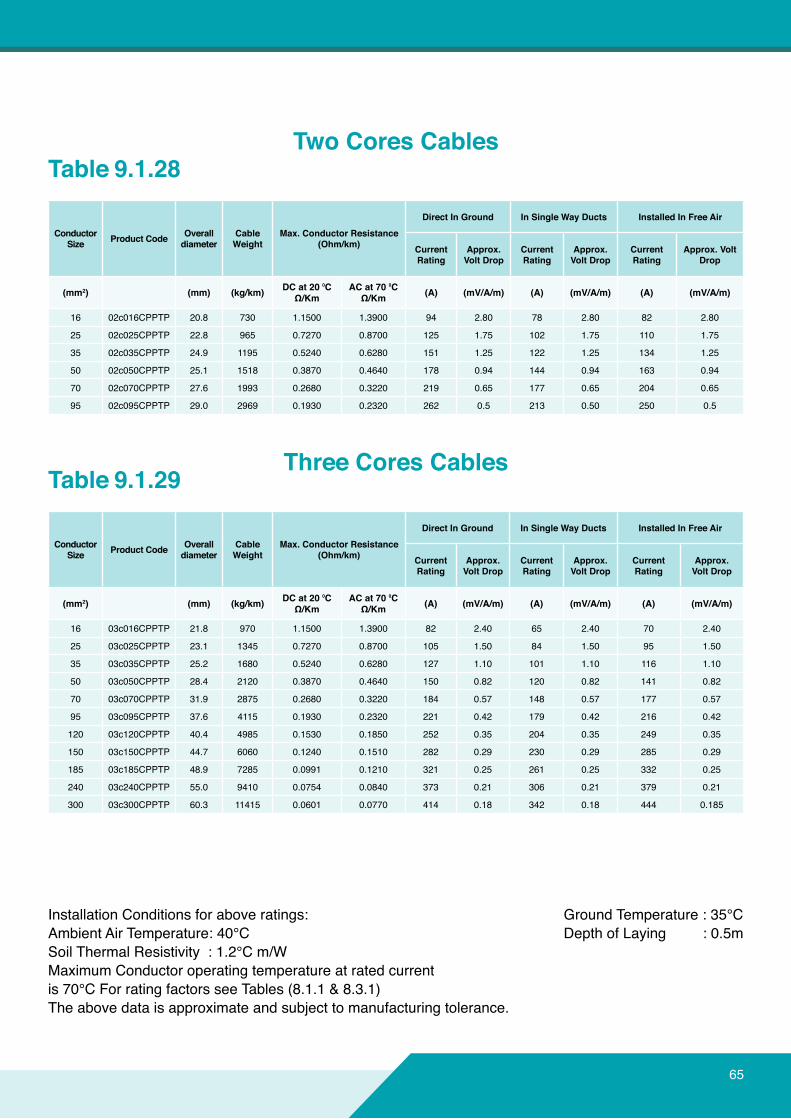
Installation Conditions for above ratings:Ambient Air Temperature: 40°CSoil Thermal Resistivity : 1.2°C m/WMaximumConductoroperatingtemperatureatratedcurrentis 70°C For rating factors see Tables (8.1.1 & 8.3.1)Theabovedataisapproximateandsubjecttomanufacturingtolerance.
Ground Temperature : 35°C Depth of Laying : 0.5m
Table 9.1.28
Table 9.1.29
ConductorSize ProductCode Overall
diameterCable Weight
Max.ConductorResistance(Ohm/km)
DirectInGround InSingleWayDucts InstalledInFreeAir
CurrentRating
Approx.VoltDrop
CurrentRating
Approx.VoltDrop
CurrentRating
Approx.VoltDrop
(mm2) (mm) (kg/km) DCat20⁰CΩ/Km
ACat70⁰CΩ/Km (A) (mV/A/m) (A) (mV/A/m) (A) (mV/A/m)
16 02c016CPPTP 20.8 730 1.1500 1.3900 94 2.80 78 2.80 82 2.80
25 02c025CPPTP 22.8 965 0.7270 0.8700 125 1.75 102 1.75 110 1.75
35 02c035CPPTP 24.9 1195 0.5240 0.6280 151 1.25 122 1.25 134 1.25
50 02c050CPPTP 25.1 1518 0.3870 0.4640 178 0.94 144 0.94 163 0.94
70 02c070CPPTP 27.6 1993 0.2680 0.3220 219 0.65 177 0.65 204 0.65
95 02c095CPPTP 29.0 2969 0.1930 0.2320 262 0.5 213 0.50 250 0.5
ConductorSize ProductCode Overall
diameterCable Weight
Max.ConductorResistance(Ohm/km)
DirectInGround InSingleWayDucts InstalledInFreeAir
CurrentRating
Approx.VoltDrop
CurrentRating
Approx.VoltDrop
CurrentRating
Approx.VoltDrop
(mm2) (mm) (kg/km) DCat20⁰CΩ/Km
ACat70⁰CΩ/Km (A) (mV/A/m) (A) (mV/A/m) (A) (mV/A/m)
16 03c016CPPTP 21.8 970 1.1500 1.3900 82 2.40 65 2.40 70 2.40
25 03c025CPPTP 23.1 1345 0.7270 0.8700 105 1.50 84 1.50 95 1.50
35 03c035CPPTP 25.2 1680 0.5240 0.6280 127 1.10 101 1.10 116 1.10
50 03c050CPPTP 28.4 2120 0.3870 0.4640 150 0.82 120 0.82 141 0.82
70 03c070CPPTP 31.9 2875 0.2680 0.3220 184 0.57 148 0.57 177 0.57
95 03c095CPPTP 37.6 4115 0.1930 0.2320 221 0.42 179 0.42 216 0.42
120 03c120CPPTP 40.4 4985 0.1530 0.1850 252 0.35 204 0.35 249 0.35
150 03c150CPPTP 44.7 6060 0.1240 0.1510 282 0.29 230 0.29 285 0.29
185 03c185CPPTP 48.9 7285 0.0991 0.1210 321 0.25 261 0.25 332 0.25
240 03c240CPPTP 55.0 9410 0.0754 0.0840 373 0.21 306 0.21 379 0.21
300 03c300CPPTP 60.3 11415 0.0601 0.0770 414 0.18 342 0.18 444 0.185
TwoCoresCables
Three Cores Cables
65
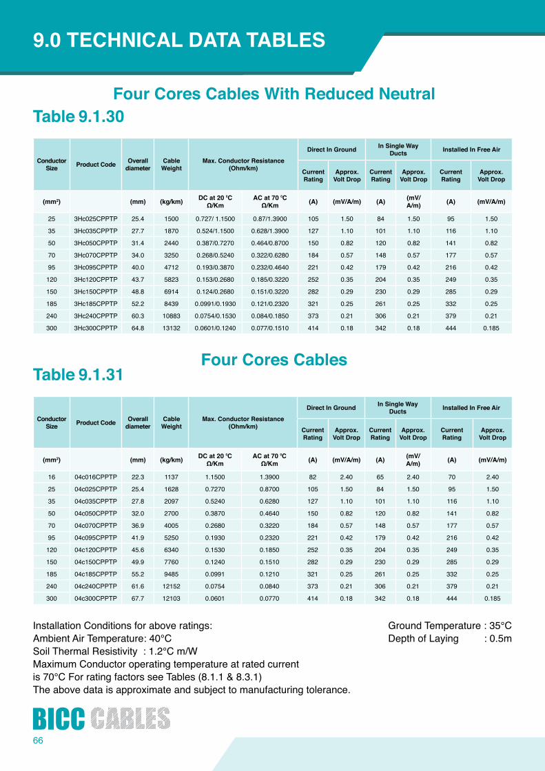
66
ConductorSize ProductCode Overall
diameterCable Weight
Max.ConductorResistance(Ohm/km)
DirectInGround In Single Way Ducts InstalledInFreeAir
CurrentRating
Approx.VoltDrop
CurrentRating
Approx.VoltDrop
CurrentRating
Approx.VoltDrop
(mm2) (mm) (kg/km) DCat20⁰CΩ/Km
ACat70⁰CΩ/Km (A) (mV/A/m) (A) (mV/
A/m) (A) (mV/A/m)
25 3Hc025CPPTP 25.4 1500 0.727/ 1.1500 0.87/1.3900 105 1.50 84 1.50 95 1.50
35 3Hc035CPPTP 27.7 1870 0.524/1.1500 0.628/1.3900 127 1.10 101 1.10 116 1.10
50 3Hc050CPPTP 31.4 2440 0.387/0.7270 0.464/0.8700 150 0.82 120 0.82 141 0.82
70 3Hc070CPPTP 34.0 3250 0.268/0.5240 0.322/0.6280 184 0.57 148 0.57 177 0.57
95 3Hc095CPPTP 40.0 4712 0.193/0.3870 0.232/0.4640 221 0.42 179 0.42 216 0.42
120 3Hc120CPPTP 43.7 5823 0.153/0.2680 0.185/0.3220 252 0.35 204 0.35 249 0.35
150 3Hc150CPPTP 48.8 6914 0.124/0.2680 0.151/0.3220 282 0.29 230 0.29 285 0.29
185 3Hc185CPPTP 52.2 8439 0.0991/0.1930 0.121/0.2320 321 0.25 261 0.25 332 0.25
240 3Hc240CPPTP 60.3 10883 0.0754/0.1530 0.084/0.1850 373 0.21 306 0.21 379 0.21
300 3Hc300CPPTP 64.8 13132 0.0601/0.1240 0.077/0.1510 414 0.18 342 0.18 444 0.185
INTRODUCTION9.0TECHNICALDATATABLES
Installation Conditions for above ratings:Ambient Air Temperature: 40°CSoil Thermal Resistivity : 1.2°C m/WMaximumConductoroperatingtemperatureatratedcurrentis 70°C For rating factors see Tables (8.1.1 & 8.3.1)Theabovedataisapproximateandsubjecttomanufacturingtolerance.
Ground Temperature : 35°C Depth of Laying : 0.5m
Table 9.1.30
Table 9.1.31
ConductorSize ProductCode Overall
diameterCable Weight
Max.ConductorResistance(Ohm/km)
DirectInGround In Single Way Ducts InstalledInFreeAir
CurrentRating
Approx.VoltDrop
CurrentRating
Approx.VoltDrop
CurrentRating
Approx.VoltDrop
(mm2) (mm) (kg/km) DCat20⁰CΩ/Km
ACat70⁰CΩ/Km (A) (mV/A/m) (A) (mV/
A/m) (A) (mV/A/m)
16 04c016CPPTP 22.3 1137 1.1500 1.3900 82 2.40 65 2.40 70 2.40
25 04c025CPPTP 25.4 1628 0.7270 0.8700 105 1.50 84 1.50 95 1.50
35 04c035CPPTP 27.8 2097 0.5240 0.6280 127 1.10 101 1.10 116 1.10
50 04c050CPPTP 32.0 2700 0.3870 0.4640 150 0.82 120 0.82 141 0.82
70 04c070CPPTP 36.9 4005 0.2680 0.3220 184 0.57 148 0.57 177 0.57
95 04c095CPPTP 41.9 5250 0.1930 0.2320 221 0.42 179 0.42 216 0.42
120 04c120CPPTP 45.6 6340 0.1530 0.1850 252 0.35 204 0.35 249 0.35
150 04c150CPPTP 49.9 7760 0.1240 0.1510 282 0.29 230 0.29 285 0.29
185 04c185CPPTP 55.2 9485 0.0991 0.1210 321 0.25 261 0.25 332 0.25
240 04c240CPPTP 61.6 12152 0.0754 0.0840 373 0.21 306 0.21 379 0.21
300 04c300CPPTP 67.7 12103 0.0601 0.0770 414 0.18 342 0.18 444 0.185
FourCoresCablesWithReducedNeutral
FourCoresCables

67
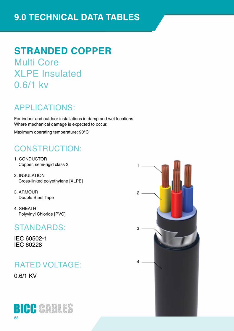
68
1
2
3
4
STRANDEDCOPPERMulti CoreXLPE Insulated0.6/1 kv
APPLICATIONS:
CONSTRUCTION:
STANDARDS:
RATED VOLTAGE:
INTRODUCTION9.0TECHNICALDATATABLES
For indoor and outdoor installations in damp and wet locations.Wheremechanicaldamageisexpectedtooccur.
Maximumoperatingtemperature:90°C
1. CONDUCTORCopper, semi-rigid class 2
2. INSULATIONCross-linked polyethylene [XLPE]
3. ARMOURDouble Steel Tape
4. SHEATHPolyvinyl Chloride [PVC]
IEC 60502-1IEC 60228
0.6/1 KV
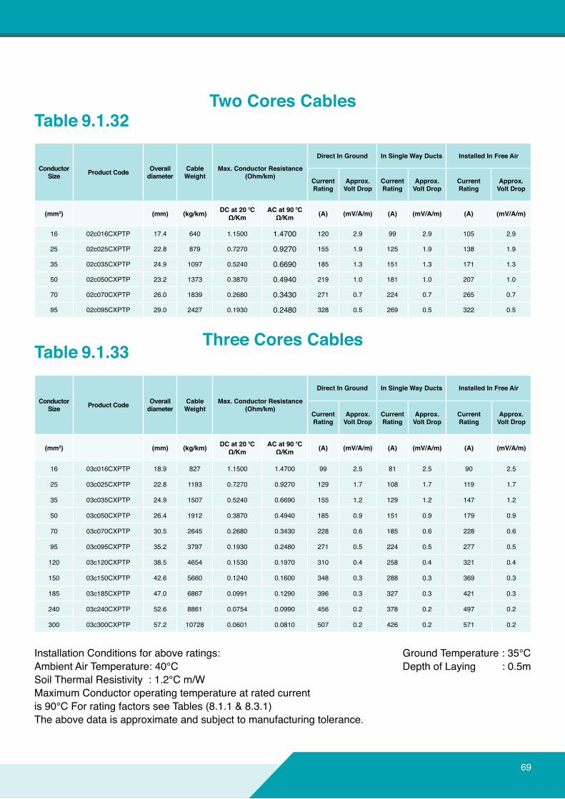
Installation Conditions for above ratings:Ambient Air Temperature: 40°CSoil Thermal Resistivity : 1.2°C m/WMaximumConductoroperatingtemperatureatratedcurrentis 90°C For rating factors see Tables (8.1.1 & 8.3.1)Theabovedataisapproximateandsubjecttomanufacturingtolerance.
Ground Temperature : 35°C Depth of Laying : 0.5m
Table 9.1.32
Table 9.1.33
ConductorSize ProductCode Overall
diameterCable Weight
Max.ConductorResistance(Ohm/km)
DirectInGround InSingleWayDucts InstalledInFreeAir
CurrentRating
Approx.VoltDrop
CurrentRating
Approx.VoltDrop
CurrentRating
Approx.VoltDrop
(mm2) (mm) (kg/km) DCat20⁰CΩ/Km
ACat90⁰CΩ/Km (A) (mV/A/m) (A) (mV/A/m) (A) (mV/A/m)
16 02c016CXPTP 17.4 640 1.1500 1.4700 120 2.9 99 2.9 105 2.9
25 02c025CXPTP 22.8 879 0.7270 0.9270 155 1.9 125 1.9 138 1.9
35 02c035CXPTP 24.9 1097 0.5240 0.6690 185 1.3 151 1.3 171 1.3
50 02c050CXPTP 23.2 1373 0.3870 0.4940 219 1.0 181 1.0 207 1.0
70 02c070CXPTP 26.0 1839 0.2680 0.3430 271 0.7 224 0.7 265 0.7
95 02c095CXPTP 29.0 2427 0.1930 0.2480 328 0.5 269 0.5 322 0.5
ConductorSize ProductCode Overall
diameterCable Weight
Max.ConductorResistance(Ohm/km)
DirectInGround InSingleWayDucts InstalledInFreeAir
CurrentRating
Approx.VoltDrop
CurrentRating
Approx.VoltDrop
CurrentRating
Approx.VoltDrop
(mm2) (mm) (kg/km) DCat20⁰CΩ/Km
ACat90⁰CΩ/Km (A) (mV/A/m) (A) (mV/A/m) (A) (mV/A/m)
16 03c016CXPTP 18.9 827 1.1500 1.4700 99 2.5 81 2.5 90 2.5
25 03c025CXPTP 22.8 1193 0.7270 0.9270 129 1.7 108 1.7 119 1.7
35 03c035CXPTP 24.9 1507 0.5240 0.6690 155 1.2 129 1.2 147 1.2
50 03c050CXPTP 26.4 1912 0.3870 0.4940 185 0.9 151 0.9 179 0.9
70 03c070CXPTP 30.5 2645 0.2680 0.3430 228 0.6 185 0.6 228 0.6
95 03c095CXPTP 35.2 3797 0.1930 0.2480 271 0.5 224 0.5 277 0.5
120 03c120CXPTP 38.5 4654 0.1530 0.1970 310 0.4 258 0.4 321 0.4
150 03c150CXPTP 42.6 5660 0.1240 0.1600 348 0.3 288 0.3 369 0.3
185 03c185CXPTP 47.0 6867 0.0991 0.1290 396 0.3 327 0.3 421 0.3
240 03c240CXPTP 52.6 8861 0.0754 0.0990 456 0.2 378 0.2 497 0.2
300 03c300CXPTP 57.2 10728 0.0601 0.0810 507 0.2 426 0.2 571 0.2
TwoCoresCables
Three Cores Cables
69

70
ConductorSize ProductCode Overall
diameterCable Weight
Max.ConductorResistance(Ohm/km)
DirectInGround In Single Way Ducts InstalledInFreeAir
CurrentRating
Approx.VoltDrop
CurrentRating
Approx.VoltDrop
CurrentRating
Approx.VoltDrop
(mm2) (mm) (kg/km) DCat20⁰CΩ/Km
ACat90⁰CΩ/Km (A) (mV/A/m) (A) (mV/
A/m) (A) (mV/A/m)
25 3Hc025CXPTP 23.8 1352 0.727/ 1.1500 0.927/1.4700 129 1.7 108 1.7 119 1.7
35 3Hc035CXPTP 26.1 1696 0.524/1.1500 0.669/1.4700 155 1.2 129 1.2 147 1.2
50 3Hc050CXPTP 29.2 2210 0.387/0.7270 0.494/0.9270 185 0.9 151 0.9 179 0.9
70 3Hc070CXPTP 32.4 3012 0.268/0.5240 0.343/0.6690 228 0.6 185 0.6 228 0.6
95 3Hc095CXPTP 37.2 4328 0.193/0.3870 0.248/0.4940 271 0.5 224 0.5 277 0.5
120 3Hc120CXPTP 41.1 5385 0.153/0.2680 0.197/0.3430 310 0.4 258 0.4 321 0.4
150 3Hc150CXPTP 46.5 6466 0.124/0.2680 0.16/0.3430 348 0.3 288 0.3 369 0.3
185 3Hc185CXPTP 49.9 7898 0.0991/0.1930 0.129/0.2480 396 0.3 327 0.3 421 0.3
240 3Hc240CXPTP 57.4 10209 0.0754/0.1530 0.099/0.1970 456 0.2 378 0.2 497 0.2
300 3Hc300CXPTP 61.4 12339 0.0601/0.1240 0.081/0.1600 507 0.2 426 0.2 571 0.2
INTRODUCTION9.0TECHNICALDATATABLES
Installation Conditions for above ratings:Ambient Air Temperature: 40°CSoil Thermal Resistivity : 1.2°C m/WMaximumConductoroperatingtemperatureatratedcurrentis 90°C For rating factors see Tables (8.1.1 & 8.3.1)Theabovedataisapproximateandsubjecttomanufacturingtolerance.
Ground Temperature : 35°C Depth of Laying : 0.5m
Table 9.1.34
Table 9.1.35
ConductorSize ProductCode Overall
diameterCable Weight
Max.ConductorResistance(Ohm/km)
DirectInGround In Single Way Ducts InstalledInFreeAir
CurrentRating
Approx.VoltDrop
CurrentRating
Approx.VoltDrop
CurrentRating
Approx.VoltDrop
(mm2) (mm) (kg/km) DCat20⁰CΩ/Km
ACat90⁰CΩ/Km (A) (mV/A/m) (A) (mV/
A/m) (A) (mV/A/m)
16 04c016CXPTP 20.6 1055 1.1500 1.4700 99 2.5 81 2.5 90 2.5
25 04c025CXPTP 23.8 1466 0.7270 0.9270 129 1.7 108 1.7 119 1.7
35 04c035CXPTP 26.1 1901 0.5240 0.6690 155 1.2 129 1.2 147 1.2
50 04c050CXPTP 29.3 2430 0.3870 0.4940 185 0.9 151 0.9 179 0.9
70 04c070CXPTP 35.2 3731 0.2680 0.3430 228 0.6 185 0.6 228 0.6
95 04c095CXPTP 39.0 4838 0.1930 0.2480 271 0.5 224 0.5 277 0.5
120 04c120CXPTP 43.2 5979 0.1530 0.1970 310 0.4 258 0.4 321 0.4
150 04c150CXPTP 47.5 7277 0.1240 0.1600 348 0.3 288 0.3 369 0.3
185 04c185CXPTP 52.5 8866 0.0991 0.1290 396 0.3 327 0.3 421 0.3
240 04c240CXPTP 58.8 11446 0.0754 0.0990 456 0.2 378 0.2 497 0.2
300 04c300CXPTP 62.2 13954 0.0601 0.0810 507 0.2 426 0.2 571 0.2
FourCoresCablesWithReducedNeutral
FourCoresCables
Wearethebestinoverheadtransmissionanddistributionbareconductors.
71

72
1
2
3
4
STRANDEDALUMINUMMulti CorePVC Insulated0.6/1 kv
APPLICATIONS:
CONSTRUCTION:
STANDARDS:
RATED VOLTAGE:
INTRODUCTION9.0TECHNICALDATATABLES
For indoor and outdoor installations in damp and wet locations.Wheremechanicaldamageisexpectedtooccur.
Maximumoperatingtemperature:70°C
1. CONDUCTORAluminum, semi-rigid class 2
2. INSULATIONPolyvinyl Chloride [PVC]
3. ARMOURDouble Steel Tape
4. SHEATHPolyvinyl Chloride [PVC]
IEC 60502-1IEC 60228
0.6/1 KV

Installation Conditions for above ratings:Ambient Air Temperature: 40°CSoil Thermal Resistivity : 1.2°C m/WMaximumConductoroperatingtemperatureatratedcurrentis 70°C For rating factors see Tables (8.1.1 & 8.3.1)Theabovedataisapproximateandsubjecttomanufacturingtolerance.
Ground Temperature : 35°C Depth of Laying : 0.5m
Table 9.1.36
Table 9.1.37
ConductorSize ProductCode Overall
diameterCable Weight
Max.ConductorResistance(Ohm/km)
DirectInGround InSingleWayDucts InstalledInFreeAir
CurrentRating
Approx.VoltDrop
CurrentRating
Approx.VoltDrop
CurrentRating
Approx.VoltDrop
(mm2) (mm) (kg/km) DCat20⁰CΩ/Km
ACat70⁰CΩ/Km (A) (mV/A/m) (A) (mV/A/m) (A) (mV/A/m)
16 02c016APPTP 20.8 540 1.910 2.2900 73 4.50 60 4.50 61 4.50
25 02c025APPTP 22.8 655 1.200 1.4400 94 2.90 78 2.90 81 2.90
35 02c035APPTP 24.9 760 0.868 1.0400 112 2.10 94 2.10 99 2.10
50 02c050APPTP 25.1 935 0.6410 0.7710 132 1.55 111 1.55 119 1.55
70 02c070APPTP 27.6 1148 0.4430 0.5330 166 1.05 137 1.05 150 1.05
95 02c095APPTP 29.0 1793 0.3200 0.3850 199 0.79 164 0.79 182 0.79
ConductorSize ProductCode Overall
diameterCable Weight
Max.ConductorResistance(Ohm/km)
DirectInGround InSingleWayDucts InstalledInFreeAir
CurrentRating
Approx.VoltDrop
CurrentRating
Approx.VoltDrop
CurrentRating
Approx.VoltDrop
(mm2) (mm) (kg/km) DCat20⁰CΩ/Km
ACat70⁰CΩ/Km (A) (mV/A/m) (A) (mV/A/m) (A) (mV/A/m)
16 03c016APPTP 21.8 670 1.910 2.2900 62 3.90 51 3.90 53 3.90
25 03c025APPTP 23.1 870 1.200 1.4400 81 2.50 65 2.50 68 2.50
35 03c035APPTP 25.2 1030 0.868 1.0400 97 1.80 79 1.80 84 1.80
50 03c050APPTP 28.4 1235 0.6410 0.7710 115 1.35 93 1.35 102 1.35
70 03c070APPTP 31.9 1595 0.4430 0.5330 141 0.92 115 0.92 129 0.92
95 03c095APPTP 37.6 2350 0.3200 0.3850 169 0.68 139 0.68 158 0.68
120 03c120APPTP 40.4 2745 0.2530 0.3050 193 0.55 158 0.55 182 0.55
150 03c150APPTP 44.7 3285 0.2060 0.2490 216 0.44 178 0.44 212 0.44
185 03c185APPTP 48.9 3835 0.1640 0.1990 246 0.37 203 0.37 244 0.37
240 03c240APPTP 55.0 4825 0.1250 0.1510 286 0.3 237 0.30 290 0.3
300 03c300APPTP 60.3 5745 0.1000 0.1230 305 0.26 262 0.26 340 0.26
TwoCoresCables
Three Cores Cables
73

74
ConductorSize ProductCode Overall
diameterCable Weight
Max.ConductorResistance(Ohm/km)
DirectInGround InSingleWayDucts InstalledInFreeAir
CurrentRating
Approx.VoltDrop
CurrentRating
Approx.VoltDrop
CurrentRating
Approx.VoltDrop
(mm2) (mm) (kg/km) DCat20⁰CΩ/Km
ACat70⁰CΩ/Km (A) (mV/A/m) (A) (mV/A/m) (A) (mV/
A/m)
25 3Hc025APPTP 25.4 942 1.200/1.1910 1.440/2.290 81 2.50 65 2.50 68 2.50
35 3Hc035APPTP 27.7 1123 0.868/1.9100 1.0430/2.2900 97 1.80 79 1.80 84 1.80
50 3Hc050APPTP 31.4 1399 0.641/1.2000 0.7710/1.4400 115 1.35 93 1.35 102 1.35
70 3Hc070APPTP 34.0 1762 0.443/0.8680 0.5330/1.0400 141 0.92 115 0.92 129 0.92
95 3Hc095APPTP 40.0 2655 0.32/0.6410 0.3850/0.7710 169 0.68 139 0.68 158 0.68
120 3Hc120APPTP 43.7 3162 0.253/0.4430 0.3050/0.5330 193 0.55 158 0.55 182 0.55
150 3Hc150APPTP 48.8 3710 0.206/0.4430 0.2490/0.5330 216 0.44 178 0.44 212 0.44
185 3Hc185APPTP 52.2 4409 0.164/0.3200 0.1990/0.3850 246 0.37 203 0.37 244 0.37
240 3Hc240APPTP 60.3 5551 0.125/0.2530 0.1510/0.3050 286 0.30 237 0.30 290 0.30
300 3Hc300APPTP 64.8 6530 0.1/0.2060 0.1230/0.2490 305 0.26 262 0.26 340 0.26
INTRODUCTION9.0TECHNICALDATATABLES
Installation Conditions for above ratings:Ambient Air Temperature: 40°CSoil Thermal Resistivity : 1.2°C m/WMaximumConductoroperatingtemperatureatratedcurrentis 70°C For rating factors see Tables (8.1.1 & 8.3.1)Theabovedataisapproximateandsubjecttomanufacturingtolerance.
Ground Temperature : 35°C Depth of Laying : 0.5m
Table 9.1.38
Table 9.1.39
ConductorSize ProductCode Overall
diameterCable Weight
Max.ConductorResistance(Ohm/km)
DirectInGround InSingleWayDucts InstalledInFreeAir
CurrentRating
Approx.VoltDrop
CurrentRating
Approx.VoltDrop
CurrentRating
Approx.VoltDrop
(mm2) (mm) (kg/km) DCat20⁰CΩ/Km
ACat70⁰CΩ/Km (A) (mV/A/m) (A) (mV/A/m) (A) (mV/
A/m)
16 04c016APPTP 22.3 756 1.910 2.2900 62 3.90 51 3.90 53 3.90
25 04c025APPTP 25.4 1002 1.200 1.4400 81 2.50 65 2.50 68 2.50
35 04c035APPTP 27.8 1219 0.868 1.0400 97 1.80 79 1.80 84 1.80
50 04c050APPTP 32.0 1520 0.6410 0.7710 115 1.35 93 1.35 102 1.35
70 04c070APPTP 36.9 2307 0.4430 0.5330 141 0.92 115 0.92 129 0.92
95 04c095APPTP 41.9 2888 0.3200 0.3850 169 0.68 139 0.68 158 0.68
120 04c120APPTP 45.6 3390 0.2530 0.3050 193 0.55 158 0.55 182 0.55
150 04c150APPTP 49.9 4049 0.2060 0.2490 216 0.44 178 0.44 212 0.44
185 04c185APPTP 55.2 4889 0.1640 0.1990 246 0.37 203 0.37 244 0.37
240 04c240APPTP 61.6 6031 0.1250 0.1510 286 0.3 237 0.30 290 0.3
300 04c300APPTP 67.7 7326 0.1000 0.1230 305 0.26 262 0.26 340 0.26-
FourCoresCablesWithReducedNeutral
FourCoresCables
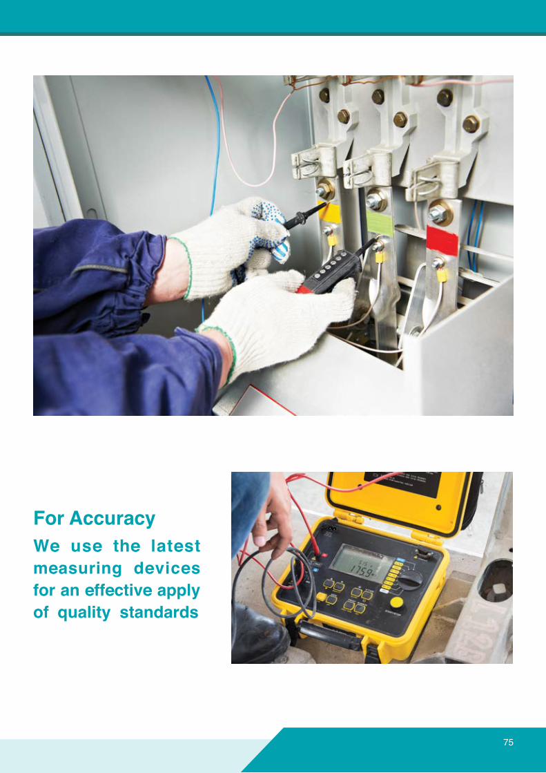
We use the latestmeasuring devicesforaneffectiveapplyof quality standards
ForAccuracy
75
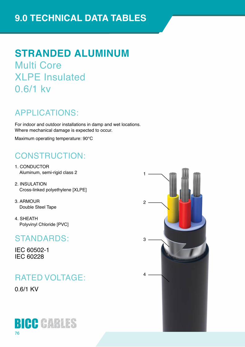
76
1
2
3
4
STRANDEDALUMINUMMulti CoreXLPE Insulated0.6/1 kv
APPLICATIONS:
CONSTRUCTION:
STANDARDS:
RATED VOLTAGE:
INTRODUCTION9.0TECHNICALDATATABLES
For indoor and outdoor installations in damp and wet locations.Wheremechanicaldamageisexpectedtooccur.
Maximumoperatingtemperature:90°C
1. CONDUCTORAluminum, semi-rigid class 2
2. INSULATIONCross-linked polyethylene [XLPE]
3. ARMOURDouble Steel Tape
4. SHEATHPolyvinyl Chloride [PVC]
IEC 60502-1IEC 60228
0.6/1 KV

Installation Conditions for above ratings:Ambient Air Temperature: 40°CSoil Thermal Resistivity : 1.2°C m/WMaximumConductoroperatingtemperatureatratedcurrentis 90°C For rating factors see Tables (8.1.1 & 8.3.1)Theabovedataisapproximateandsubjecttomanufacturingtolerance.
Ground Temperature : 35°C Depth of Laying : 0.5m
Table 9.1.40
Table 9.1.41
ConductorSize ProductCode Overall
diameterCable Weight
Max.ConductorResistance(Ohm/km)
DirectInGround InSingleWayDucts InstalledInFreeAir
CurrentRating
Approx.VoltDrop
CurrentRating
Approx.VoltDrop
CurrentRating
Approx.VoltDrop
(mm2) (mm) (kg/km) DCat20⁰CΩ/Km
ACat90⁰CΩ/Km (A) (mV/A/m) (A) (mV/A/m) (A) (mV/
A/m)
16 02c016AXPTP 17.4 450 1.910 2.4500 90 4.7 73 4.7 82 4.7
25 02c025AXPTP 21.6 568 1.200 1.5400 116 3.1 95 3.1 102 3.1
35 02c035AXPTP 23.7 662 0.868 1.1130 142 2.2 112 2.2 126 2.2
50 02c050AXPTP 22.0 783 0.6410 0.8220 168 1.7 133 1.7 151 1.7
70 02c070AXPTP 26.0 991 0.4430 0.5690 206 1.1 168 1.1 192 1.1
95 02c095AXPTP 29.0 1249 0.3200 0.4110 248 0.8 204 0.8 231 0.8
ConductorSize ProductCode Overall
diameterCable Weight
Max.ConductorResistance(Ohm/km)
DirectInGround InSingleWayDucts InstalledInFreeAir
CurrentRating
Approx.VoltDrop
CurrentRating
Approx.VoltDrop
CurrentRating
Approx.VoltDrop
(mm2) (mm) (kg/km) DCat20⁰CΩ/Km
ACat90⁰CΩ/Km (A) (mV/A/m) (A) (mV/A/m) (A) (mV/
A/m)
16 03c016AXPTP 18.9 541 1.910 2.4500 77 4.2 62 4.2 67 4.2
25 03c025AXPTP 21.7 726 1.200 1.5400 99 2.7 81 2.7 89 2.7
35 03c035AXPTP 23.7 854 0.868 1.1130 116 1.9 95 1.9 109 1.9
50 03c050AXPTP 26.4 1028 0.6410 0.8220 142 1.4 116 1.4 132 1.4
70 03c070AXPTP 30.5 1372 0.4430 0.5690 172 1.0 142 1.0 168 1.0
95 03c095AXPTP 35.2 2030 0.3200 0.4110 206 0.7 172 0.7 204 0.7
120 03c120AXPTP 38.5 2416 0.2530 0.3250 237 0.6 198 0.6 240 0.6
150 03c150AXPTP 42.6 2880 0.2060 0.2650 267 0.5 219 0.5 278 0.5
185 03c185AXPTP 47.0 3425 0.1640 0.2120 301 0.4 254 0.4 319 0.4
240 03c240AXPTP 52.6 4273 0.1250 0.1630 353 0.3 292 0.3 380 0.3
300 03c300AXPTP 57.2 5056 0.1000 0.1310 396 0.3 331 0.3 444 0.3
TwoCoresCables
Three Cores Cables
77

78
ConductorSize ProductCode Overall
diameterCable Weight
Max.ConductorResistance(Ohm/km)
DirectInGround InSingleWayDucts InstalledInFreeAir
CurrentRating
Approx.VoltDrop
CurrentRating
Approx.VoltDrop
CurrentRating
Approx.VoltDrop
(mm2) (mm) (kg/km) DCat20⁰CΩ/Km
ACat90⁰CΩ/Km (A) (mV/A/m) (A) (mV/A/m) (A) (mV/
A/m)
25 3Hc025AXPTP 23.8 790 1.200/1.1910 1.5400/2.4500 99 2.7 81 2.7 89 2.7
35 3Hc035AXPTP 24.8 948 0.868/1.9100 1.1130/2.4500 116 1.9 95 1.9 109 1.9
50 3Hc050AXPTP 29.2 1170 0.641/1.2000 0.8220/1.5400 142 1.4 116 1.4 132 1.4
70 3Hc070AXPTP 32.4 1552 0.443/0.8680 0.5690/1.1130 172 1.0 142 1.0 168 1.0
95 3Hc095AXPTP 37.2 2267 0.32/0.6410 0.4110/0.8220 206 0.7 172 0.7 204 0.7
120 3Hc120AXPTP 41.1 2722 0.253/0.4430 0.3250/0.5690 237 0.6 198 0.6 240 0.6
150 3Hc150AXPTP 46.5 3262 0.206/0.4430 0.2650/0.5690 267 0.5 219 0.5 278 0.5
185 3Hc185AXPTP 49.9 3867 0.164/0.3200 0.2120/0.4110 301 0.4 254 0.4 319 0.4
240 3Hc240AXPTP 57.4 4875 0.125/0.2530 0.1630/0.3250 353 0.3 292 0.3 380 0.3
300 3Hc300AXPTP 61.4 5740 0.1000/0.2060 0.1310/0.2650 396 0.3 331 0.3 444 0.3
INTRODUCTION9.0TECHNICALDATATABLES
Installation Conditions for above ratings:Ambient Air Temperature: 40°CSoil Thermal Resistivity : 1.2°C m/WMaximumConductoroperatingtemperatureatratedcurrentis 90°C For rating factors see Tables (8.1.1 & 8.3.1)Theabovedataisapproximateandsubjecttomanufacturingtolerance.
Ground Temperature : 35°C Depth of Laying : 0.5m
Table 9.1.42
Table 9.1.43
ConductorSize ProductCode Overall
diameterCable Weight
Max.ConductorResistance(Ohm/km)
DirectInGround InSingleWayDucts InstalledInFreeAir
CurrentRating
Approx.VoltDrop
CurrentRating
Approx.VoltDrop
CurrentRating
Approx.VoltDrop
(mm2) (mm) (kg/km) DCat20⁰CΩ/Km
ACat90⁰CΩ/Km (A) (mV/A/m) (A) (mV/A/m) (A) (mV/
A/m)
16 04c016AXPTP 20.6 674 1.910 2.4500 77 4.2 62 4.2 67 4.2
25 04c025AXPTP 23.8 844 1.200 1.5400 99 2.7 81 2.7 89 2.7
35 04c035AXPTP 26.1 1030 0.868 1.1130 116 1.9 95 1.9 109 1.9
50 04c050AXPTP 29.3 1251 0.6410 0.8220 142 1.4 116 1.4 132 1.4
70 04c070AXPTP 35.2 2034 0.4430 0.5690 172 1.0 142 1.0 168 1.0
95 04c095AXPTP 39.0 2483 0.3200 0.4110 206 0.7 172 0.7 204 0.7
120 04c120AXPTP 43.2 2994 0.2530 0.3250 237 0.6 198 0.6 240 0.6
150 04c150AXPTP 47.5 3570 0.2060 0.2650 267 0.5 219 0.5 278 0.5
185 04c185AXPTP 52.5 4276 0.1640 0.2120 301 0.4 254 0.4 319 0.4
240 04c240AXPTP 58.8 5327 0.1250 0.1630 353 0.3 292 0.3 380 0.3
300 04c300AXPTP 64.3 6391 0.1000 0.1310 396 0.3 331 0.3 444 0.3
FourCoresCablesWithReducedNeutral
FourCoresCables
79
HighqualityproductsThatConformandapplytodomestic
andinternationalstandards
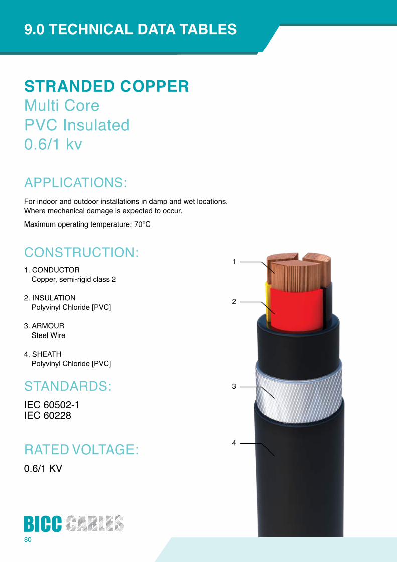
80
1
2
3
4
STRANDEDCOPPERMulti CorePVC Insulated0.6/1 kv
APPLICATIONS:
CONSTRUCTION:
STANDARDS:
RATED VOLTAGE:
INTRODUCTION9.0TECHNICALDATATABLES
For indoor and outdoor installations in damp and wet locations.Wheremechanicaldamageisexpectedtooccur.
Maximumoperatingtemperature:70°C
1. CONDUCTORCopper, semi-rigid class 2
2. INSULATIONPolyvinyl Chloride [PVC]
3. ARMOURSteel Wire
4. SHEATHPolyvinyl Chloride [PVC]
IEC 60502-1IEC 60228
0.6/1 KV

81
Installation Conditions for above ratings:Ambient Air Temperature: 40°CSoil Thermal Resistivity : 1.2°C m/WMaximumConductoroperatingtemperatureatratedcurrentis 70°C For rating factors see Tables (8.1.1 & 8.3.1)Theabovedataisapproximateandsubjecttomanufacturingtolerance.
Ground Temperature : 35°C Depth of Laying : 0.5m
Table 9.1.44
Table 9.1.45
ConductorSize ProductCode Overall
diameterCable Weight
Max.ConductorResistance(Ohm/km)
DirectInGround In Single Way Ducts InstalledInFreeAir
CurrentRating
Approx.VoltDrop
CurrentRating
Approx.VoltDrop
CurrentRating
Approx.VoltDrop
(mm2) (mm) (kg/km) DCat20⁰CΩ/Km
ACat70⁰CΩ/Km (A) (mV/A/m) (A) (mV/A/m) (A) (mV/A/m)
16 02c016CPPWP 22.2 1011 1.1500 1.3900 96 2.80 79 2.80 84 2.80
25 02c025CPPWP 26.1 1377 0.7270 0.8700 127 1.75 103 1.75 112 1.75
35 02c035CPPWP 28.4 1641 0.5240 0.6280 153 1.25 123 1.25 136 1.25
50 02c050CPPWP 27.2 2015 0.3870 0.4640 180 0.94 146 0.94 165 0.94
70 02c070CPPWP 30.7 2753 0.2680 0.3220 222 0.65 180 0.65 209 0.65
95 02c095CPPWP 34.6 3525 0.1930 0.2320 265 0.5 216 0.50 254 0.5
ConductorSize ProductCode Overall
diameterCable Weight
Max.ConductorResistance(Ohm/km)
DirectInGround In Single Way Ducts InstalledInFreeAir
CurrentRating
Approx.VoltDrop
CurrentRating
Approx.VoltDrop
CurrentRating
Approx.VoltDrop
(mm2) (mm) (kg/km) DCat20⁰CΩ/Km
ACat70⁰CΩ/Km (A) (mV/A/m) (A) (mV/A/m) (A) (mV/A/m)
16 03c016CPPWP 23.9 1390 1.1500 1.3900 82 2.40 67 2.40 71 2.40
25 03c025CPPWP 25.2 1798 0.7270 0.8700 106 1.50 86 1.50 96 1.50
35 03c035CPPWP 27.5 2198 0.5240 0.6280 127 1.10 103 1.10 117 1.10
50 03c050CPPWP 31.5 2906 0.3870 0.4640 151 0.82 123 0.82 142 0.82
70 03c070CPPWP 35.0 3750 0.2680 0.3220 185 0.57 151 0.57 178 0.57
95 03c095CPPWP 39.5 4751 0.1930 0.2320 222 0.42 182 0.42 218 0.42
120 03c120CPPWP 43.3 6024 0.1530 0.1850 253 0.35 208 0.35 253 0.35
150 03c150CPPWP 47.6 7231 0.1240 0.1510 283 0.29 234 0.29 289 0.29
185 03c185CPPWP 51.8 8556 0.0991 0.1210 322 0.25 266 0.25 336 0.25
240 03c240CPPWP 57.9 10848 0.0754 0.0840 374 0.21 307 0.21 388 0.21
300 03c300CPPWP 63.2 12984 0.0601 0.0770 414 0.18 342 0.18 444 0.185
TwoCoresCables
Three Cores Cables

82
INTRODUCTION9.0TECHNICALDATATABLES
Installation Conditions for above ratings:Ambient Air Temperature: 40°CSoil Thermal Resistivity : 1.2°C m/WMaximumConductoroperatingtemperatureatratedcurrentis 70°C For rating factors see Tables (8.1.1 & 8.3.1)Theabovedataisapproximateandsubjecttomanufacturingtolerance.
Ground Temperature : 35°C Depth of Laying : 0.5m
Table 9.1.46
Table 9.1.47
ConductorSize ProductCode Overall
diameterCable Weight
Max.ConductorResistance(Ohm/km)
DirectInGround In Single Way Ducts InstalledInFreeAir
CurrentRating
Approx.VoltDrop
CurrentRating
Approx.VoltDrop
CurrentRating
Approx.VoltDrop
(mm2) (mm) (kg/km) DCat20⁰CΩ/Km
ACat70⁰CΩ/Km (A) (mV/A/m) (A) (mV/A/m) (A) (mV/A/m)
16 04c016CPPWP 24.4 1614 1.1500 1.3900 82 2.40 67 2.40 71 2.40
25 04c025CPPWP 27.7 2147 0.7270 0.8700 106 1.50 86 1.50 96 1.50
35 04c045CPPWP 30.2 2671 0.5240 0.6280 127 1.10 103 1.10 117 1.10
50 04c050CPPWP 35.0 3589 0.3870 0.4640 151 0.82 123 0.82 142 0.82
70 04c070CPPWP 38.8 4666 0.2680 0.3220 185 0.57 151 0.57 178 0.57
95 04c095CPPWP 44.9 6398 0.1930 0.2320 222 0.42 182 0.42 218 0.42
120 04c120CPPWP 48.5 7630 0.1530 0.1850 253 0.35 208 0.35 253 0.35
150 04c150CPPWP 52.7 9072 0.1240 0.1510 283 0.29 234 0.29 289 0.29
185 04c185CPPWP 58.1 11000 0.0991 0.1210 322 0.25 266 0.25 336 0.25
240 04c240CPPWP 64.4 13762 0.0754 0.0840 305 0.26 362 0.26 340 0.26
300 04c300CPPWP 70.7 16683 0.0601 0.0770 374 0.21 307 0.21 388 0.21
ConductorSize ProductCode Overall
diameterCable Weight
Max.ConductorResistance(Ohm/km)
DirectInGround In Single Way Ducts InstalledInFreeAir
CurrentRating
Approx.VoltDrop
CurrentRating
Approx.VoltDrop
CurrentRating
Approx.VoltDrop
(mm2) (mm) (kg/km) DCat20⁰CΩ/Km
ACat70⁰CΩ/Km (A) (mV/A/m) (A) (mV/A/m) (A) (mV/A/m)
25 3Hc025CPPWP 27.5 2010 0.727/ 1.1500 0.87/1.3900 106 1.50 86 1.50 96 1.50
35 3Hc035CPPWP 30.0 2458 0.524/1.1500 0.628/1.3900 127 1.10 103 1.10 117 1.10
50 3Hc050CPPWP 34.6 3350 0.387/0.7270 0.464/0.8700 151 0.82 123 0.82 142 0.82
70 3Hc070CPPWP 37.1 4225 0.268/0.5240 0.322/0.6280 185 0.57 151 0.57 178 0.57
95 3Hc095CPPWP 41.9 5428 0.193/0.3870 0.232/0.4640 222 0.42 182 0.42 218 0.42
120 3Hc120CPPWP 46.6 7018 0.153/0.2680 0.185/0.3220 253 0.35 208 0.35 253 0.35
150 3Hc150CPPWP 51.6 8237 0.124/0.2680 0.151/0.3220 283 0.29 234 0.29 289 0.29
185 3Hc185CPPWP 55.1 9860 0.0991/0.1930 0.121/0.2320 322 0.25 266 0.25 336 0.25
240 3Hc240CPPWP 63.2 12526 0.0754/0.1530 0.084/0.1850 374 0.21 306 0.21 388 0.21
300 3Hc300CPPWP 67.7 14895 0.0601/0.1240 0.077/0.1510 414 0.18 342 0.18 444 0.185
FourCoresCablesWithReducedNeutral
FourCoresCables

83
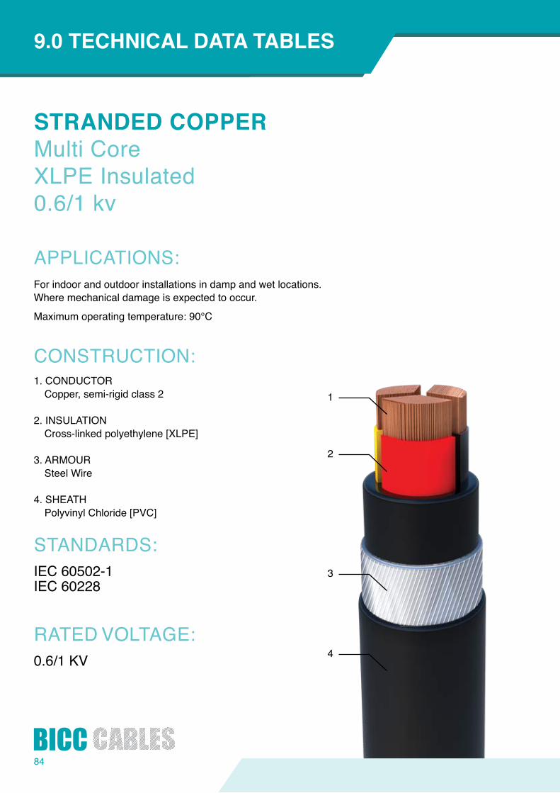
84
1
2
3
4
STRANDEDCOPPERMulti CoreXLPE Insulated0.6/1 kv
APPLICATIONS:
CONSTRUCTION:
STANDARDS:
RATED VOLTAGE:
INTRODUCTION9.0TECHNICALDATATABLES
For indoor and outdoor installations in damp and wet locations.Wheremechanicaldamageisexpectedtooccur.
Maximumoperatingtemperature:90°C
1. CONDUCTORCopper, semi-rigid class 2
2. INSULATIONCross-linked polyethylene [XLPE]
3. ARMOURSteel Wire
4. SHEATHPolyvinyl Chloride [PVC]
IEC 60502-1IEC 60228
0.6/1 KV

Installation Conditions for above ratings:Ambient Air Temperature: 40°CSoil Thermal Resistivity : 1.2°C m/WMaximumConductoroperatingtemperatureatratedcurrentis 90°C For rating factors see Tables (8.1.1 & 8.3.1)Theabovedataisapproximateandsubjecttomanufacturingtolerance.
Ground Temperature : 35°C Depth of Laying : 0.5m
Table 9.1.48
Table 9.1.49
ConductorSize ProductCode Overall
diameterCable Weight
Max.ConductorResistance(Ohm/km)
DirectInGround InSingleWayDucts InstalledInFreeAir
CurrentRating
Approx.VoltDrop
CurrentRating
Approx.VoltDrop
CurrentRating
Approx.VoltDrop
(mm2) (mm) (kg/km) DCat20⁰CΩ/Km
ACat90⁰CΩ/Km (A) (mV/A/m) (A) (mV/A/m) (A) (mV/
A/m)
16 02c016CXPWP 18.8 870 1.1500 1.4700 120 2.9 99 2.9 105 2.9
25 02c025CXPWP 24.9 1265 0.7270 0.9270 155 1.9 125 1.9 138 1.9
35 02c035CXPWP 27.0 1518 0.5240 0.6690 185 1.3 151 1.3 171 1.3
50 02c050CXPWP 25.5 1845 0.3870 0.4940 219 1.0 181 1.0 207 1.0
70 02c070CXPWP 29.1 2561 0.2680 0.3430 271 0.7 224 0.7 265 0.7
95 02c095CXPWP 32.1 3234 0.1930 0.2480 328 0.5 269 0.5 322 0.5
ConductorSize ProductCode Overall
diameterCable Weight
Max.ConductorResistance(Ohm/km)
DirectInGround InSingleWayDucts InstalledInFreeAir
CurrentRating
Approx.VoltDrop
CurrentRating
Approx.VoltDrop
CurrentRating
Approx.VoltDrop
(mm2) (mm) (kg/km) DCat20⁰CΩ/Km
ACat90⁰CΩ/Km (A) (mV/A/m) (A) (mV/A/m) (A) (mV/
A/m)
16 03c016CXPWP 20.3 1085 1.1500 1.4700 99 2.5 81 2.5 90 2.5
25 03c025CXPWP 23.8 1624 0.7270 0.9270 129 1.7 108 1.7 119 1.7
35 03c035CXPWP 25.8 1982 0.5240 0.6690 155 1.2 129 1.2 147 1.2
50 03c050CXPWP 28.5 2442 0.3870 0.4940 185 0.9 151 0.9 179 0.9
70 03c070CXPWP 33.6 3494 0.2680 0.3430 228 0.6 185 0.6 228 0.6
95 03c095CXPWP 36.9 4380 0.1930 0.2480 271 0.5 224 0.5 277 0.5
120 03c120CXPWP 40.2 5292 0.1530 0.1970 310 0.4 258 0.4 321 0.4
150 03c150CXPWP 45.5 6784 0.1240 0.1600 348 0.3 288 0.3 369 0.3
185 03c185CXPWP 49.9 8100 0.0991 0.1290 396 0.3 327 0.3 421 0.3
240 03c240CXPWP 55.5 10238 0.0754 0.0990 456 0.2 378 0.2 497 0.2
300 03c300CXPWP 60.1 12224 0.0601 0.0810 507 0.2 426 0.2 571 0.2
TwoCoresCables
Three Cores Cables
85
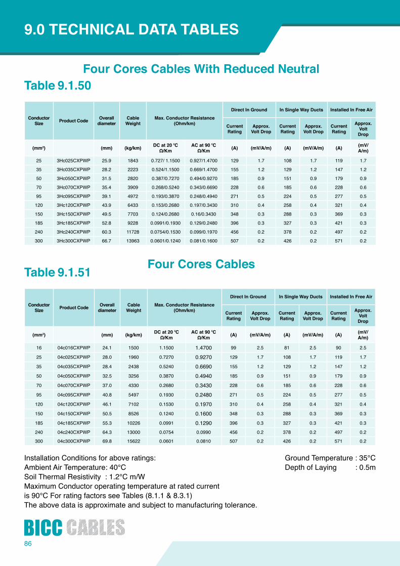
86
ConductorSize ProductCode Overall
diameterCable Weight
Max.ConductorResistance(Ohm/km)
DirectInGround InSingleWayDucts InstalledInFreeAir
CurrentRating
Approx.VoltDrop
CurrentRating
Approx.VoltDrop
CurrentRating
Approx.VoltDrop
(mm2) (mm) (kg/km) DCat20⁰CΩ/Km
ACat90⁰CΩ/Km (A) (mV/A/m) (A) (mV/A/m) (A) (mV/
A/m)
25 3Hc025CXPWP 25.9 1843 0.727/ 1.1500 0.927/1.4700 129 1.7 108 1.7 119 1.7
35 3Hc035CXPWP 28.2 2223 0.524/1.1500 0.669/1.4700 155 1.2 129 1.2 147 1.2
50 3Hc050CXPWP 31.5 2820 0.387/0.7270 0.494/0.9270 185 0.9 151 0.9 179 0.9
70 3Hc070CXPWP 35.4 3909 0.268/0.5240 0.343/0.6690 228 0.6 185 0.6 228 0.6
95 3Hc095CXPWP 39.1 4972 0.193/0.3870 0.248/0.4940 271 0.5 224 0.5 277 0.5
120 3Hc120CXPWP 43.9 6433 0.153/0.2680 0.197/0.3430 310 0.4 258 0.4 321 0.4
150 3Hc150CXPWP 49.5 7703 0.124/0.2680 0.16/0.3430 348 0.3 288 0.3 369 0.3
185 3Hc185CXPWP 52.8 9228 0.0991/0.1930 0.129/0.2480 396 0.3 327 0.3 421 0.3
240 3Hc240CXPWP 60.3 11728 0.0754/0.1530 0.099/0.1970 456 0.2 378 0.2 497 0.2
300 3Hc300CXPWP 66.7 13963 0.0601/0.1240 0.081/0.1600 507 0.2 426 0.2 571 0.2
INTRODUCTION9.0TECHNICALDATATABLES
Installation Conditions for above ratings:Ambient Air Temperature: 40°CSoil Thermal Resistivity : 1.2°C m/WMaximumConductoroperatingtemperatureatratedcurrentis 90°C For rating factors see Tables (8.1.1 & 8.3.1)Theabovedataisapproximateandsubjecttomanufacturingtolerance.
Ground Temperature : 35°C Depth of Laying : 0.5m
Table 9.1.50
Table 9.1.51
ConductorSize ProductCode Overall
diameterCable Weight
Max.ConductorResistance(Ohm/km)
DirectInGround InSingleWayDucts InstalledInFreeAir
CurrentRating
Approx.VoltDrop
CurrentRating
Approx.VoltDrop
CurrentRating
Approx.VoltDrop
(mm2) (mm) (kg/km) DCat20⁰CΩ/Km
ACat90⁰CΩ/Km (A) (mV/A/m) (A) (mV/A/m) (A) (mV/
A/m)
16 04c016CXPWP 24.1 1500 1.1500 1.4700 99 2.5 81 2.5 90 2.5
25 04c025CXPWP 28.0 1960 0.7270 0.9270 129 1.7 108 1.7 119 1.7
35 04c035CXPWP 28.4 2438 0.5240 0.6690 155 1.2 129 1.2 147 1.2
50 04c050CXPWP 32.5 3256 0.3870 0.4940 185 0.9 151 0.9 179 0.9
70 04c070CXPWP 37.0 4330 0.2680 0.3430 228 0.6 185 0.6 228 0.6
95 04c095CXPWP 40.8 5497 0.1930 0.2480 271 0.5 224 0.5 277 0.5
120 04c120CXPWP 46.1 7102 0.1530 0.1970 310 0.4 258 0.4 321 0.4
150 04c150CXPWP 50.5 8526 0.1240 0.1600 348 0.3 288 0.3 369 0.3
185 04c185CXPWP 55.3 10226 0.0991 0.1290 396 0.3 327 0.3 421 0.3
240 04c240CXPWP 64.3 13000 0.0754 0.0990 456 0.2 378 0.2 497 0.2
300 04c300CXPWP 69.8 15622 0.0601 0.0810 507 0.2 426 0.2 571 0.2
FourCoresCablesWithReducedNeutral
FourCoresCables
87
BICC Cables and theirsuppliers are linkedtogetherinco-destinytoensure thatwemeet orexceedtheexpectationsof our customers.
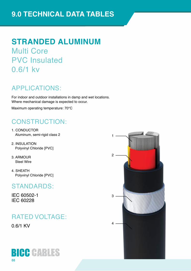
88
1
2
3
4
STRANDEDALUMINUMMulti CorePVC Insulated0.6/1 kv
APPLICATIONS:
CONSTRUCTION:
STANDARDS:
RATED VOLTAGE:
INTRODUCTION9.0TECHNICALDATATABLES
For indoor and outdoor installations in damp and wet locations.Wheremechanicaldamageisexpectedtooccur.
Maximumoperatingtemperature:70°C
1. CONDUCTORAluminum, semi-rigid class 2
2. INSULATIONPolyvinyl Chloride [PVC]
3. ARMOURSteel Wire
4. SHEATHPolyvinyl Chloride [PVC]
IEC 60502-1IEC 60228
0.6/1 KV

Installation Conditions for above ratings:Ambient Air Temperature: 40°CSoil Thermal Resistivity : 1.2°C m/WMaximumConductoroperatingtemperatureatratedcurrentis 70°C For rating factors see Tables (8.1.1 & 8.3.1)Theabovedataisapproximateandsubjecttomanufacturingtolerance.
Ground Temperature : 35°C Depth of Laying : 0.5m
Table 9.1.52
Table 9.1.53
ConductorSize ProductCode Overall
diameterCable Weight
Max.ConductorResistance(Ohm/km)
DirectInGround InSingleWayDucts InstalledInFreeAir
CurrentRating
Approx.VoltDrop
CurrentRating
Approx.VoltDrop
CurrentRating
Approx.VoltDrop
(mm2) (mm) (kg/km) DCat20⁰CΩ/Km
ACat70⁰CΩ/Km (A) (mV/A/m) (A) (mV/A/m) (A) (mV/
A/m)
16 02c016APPWP 22.2 820 1.910 2.2900 74 4.50 61 4.50 62 4.50
25 02c025APPWP 26.1 1066 1.200 1.4400 95 2.90 80 2.90 82 2.90
35 02c035APPWP 28.4 1205 0.868 1.0400 114 2.10 96 2.10 100 2.10
50 02c050APPWP 27.2 1425 0.6410 0.7710 134 1.55 113 1.55 121 1.55
70 02c070APPWP 30.7 1904 0.4430 0.5330 167 1.05 139 1.05 153 1.05
95 02c095APPWP 34.6 2347 0.3200 0.3850 200 0.79 167 0.79 185 0.79
ConductorSize ProductCode Overall
diameterCable Weight
Max.ConductorResistance(Ohm/km)
DirectInGround InSingleWayDucts InstalledInFreeAir
CurrentRating
Approx.VoltDrop
CurrentRating
Approx.VoltDrop
CurrentRating
Approx.VoltDrop
(mm2) (mm) (kg/km) DCat20⁰CΩ/Km
ACat70⁰CΩ/Km (A) (mV/A/m) (A) (mV/A/m) (A) (mV/
A/m)
16 03c016APPWP 23.9 1104 1.910 2.2900 62 3.90 52 3.90 54 3.90
25 03c025APPWP 25.2 1331 1.200 1.4400 81 2.50 67 2.50 70 2.50
35 03c035APPWP 27.5 1545 0.868 1.0400 98 1.80 80 1.80 85 1.80
50 03c050APPWP 31.5 2022 0.6410 0.7710 116 1.35 95 1.35 104 1.35
70 03c070APPWP 35.0 2477 0.4430 0.5330 142 0.92 117 0.92 131 0.92
95 03c095APPWP 39.5 2990 0.3200 0.3850 170 0.68 141 0.68 161 0.68
120 03c120APPWP 43.3 3790 0.2530 0.3050 195 0.55 162 0.55 187 0.55
150 03c150APPWP 47.6 4450 0.2060 0.2490 218 0.44 181 0.44 217 0.44
185 03c185APPWP 51.8 5115 0.1640 0.1990 248 0.37 206 0.37 249 0.37
240 03c240APPWP 57.9 6260 0.1250 0.1510 288 0.3 238 0.30 296 0.3
300 03c300APPWP 63.2 7320 0.1000 0.1230 305 0.26 262 0.26 340 0.26
TwoCoresCables
Three Cores Cables
89
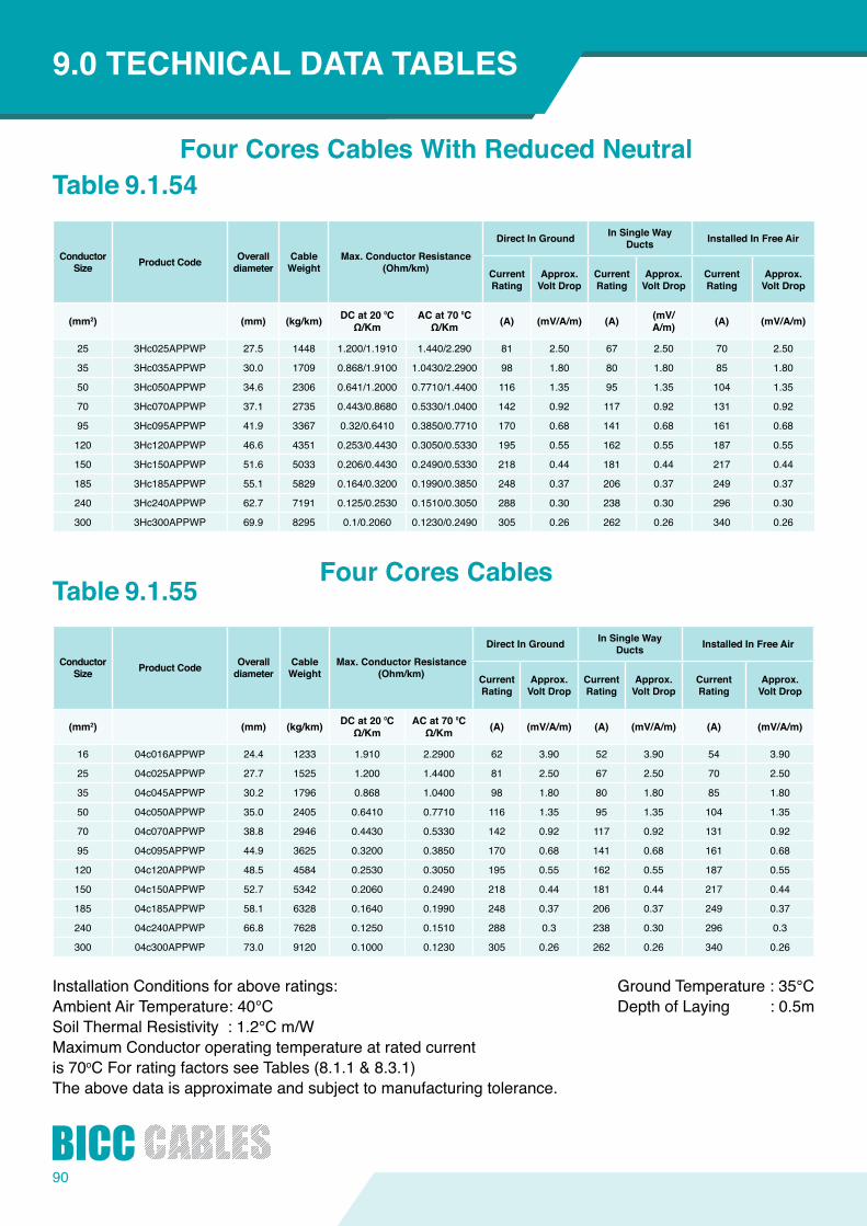
90
INTRODUCTION9.0TECHNICALDATATABLES
Installation Conditions for above ratings:Ambient Air Temperature: 40°CSoil Thermal Resistivity : 1.2°C m/WMaximumConductoroperatingtemperatureatratedcurrentis 70oC For rating factors see Tables (8.1.1 & 8.3.1)Theabovedataisapproximateandsubjecttomanufacturingtolerance.
Ground Temperature : 35°C Depth of Laying : 0.5m
Table 9.1.54
Table 9.1.55
ConductorSize ProductCode Overall
diameterCable Weight
Max.ConductorResistance(Ohm/km)
DirectInGround In Single Way Ducts InstalledInFreeAir
CurrentRating
Approx.VoltDrop
CurrentRating
Approx.VoltDrop
CurrentRating
Approx.VoltDrop
(mm2) (mm) (kg/km) DCat20⁰CΩ/Km
ACat70⁰CΩ/Km (A) (mV/A/m) (A) (mV/A/m) (A) (mV/A/m)
16 04c016APPWP 24.4 1233 1.910 2.2900 62 3.90 52 3.90 54 3.90
25 04c025APPWP 27.7 1525 1.200 1.4400 81 2.50 67 2.50 70 2.50
35 04c045APPWP 30.2 1796 0.868 1.0400 98 1.80 80 1.80 85 1.80
50 04c050APPWP 35.0 2405 0.6410 0.7710 116 1.35 95 1.35 104 1.35
70 04c070APPWP 38.8 2946 0.4430 0.5330 142 0.92 117 0.92 131 0.92
95 04c095APPWP 44.9 3625 0.3200 0.3850 170 0.68 141 0.68 161 0.68
120 04c120APPWP 48.5 4584 0.2530 0.3050 195 0.55 162 0.55 187 0.55
150 04c150APPWP 52.7 5342 0.2060 0.2490 218 0.44 181 0.44 217 0.44
185 04c185APPWP 58.1 6328 0.1640 0.1990 248 0.37 206 0.37 249 0.37
240 04c240APPWP 66.8 7628 0.1250 0.1510 288 0.3 238 0.30 296 0.3
300 04c300APPWP 73.0 9120 0.1000 0.1230 305 0.26 262 0.26 340 0.26
ConductorSize ProductCode Overall
diameterCable Weight
Max.ConductorResistance(Ohm/km)
DirectInGround In Single Way Ducts InstalledInFreeAir
CurrentRating
Approx.VoltDrop
CurrentRating
Approx.VoltDrop
CurrentRating
Approx.VoltDrop
(mm2) (mm) (kg/km) DCat20⁰CΩ/Km
ACat70⁰CΩ/Km (A) (mV/A/m) (A) (mV/
A/m) (A) (mV/A/m)
25 3Hc025APPWP 27.5 1448 1.200/1.1910 1.440/2.290 81 2.50 67 2.50 70 2.50
35 3Hc035APPWP 30.0 1709 0.868/1.9100 1.0430/2.2900 98 1.80 80 1.80 85 1.80
50 3Hc050APPWP 34.6 2306 0.641/1.2000 0.7710/1.4400 116 1.35 95 1.35 104 1.35
70 3Hc070APPWP 37.1 2735 0.443/0.8680 0.5330/1.0400 142 0.92 117 0.92 131 0.92
95 3Hc095APPWP 41.9 3367 0.32/0.6410 0.3850/0.7710 170 0.68 141 0.68 161 0.68
120 3Hc120APPWP 46.6 4351 0.253/0.4430 0.3050/0.5330 195 0.55 162 0.55 187 0.55
150 3Hc150APPWP 51.6 5033 0.206/0.4430 0.2490/0.5330 218 0.44 181 0.44 217 0.44
185 3Hc185APPWP 55.1 5829 0.164/0.3200 0.1990/0.3850 248 0.37 206 0.37 249 0.37
240 3Hc240APPWP 62.7 7191 0.125/0.2530 0.1510/0.3050 288 0.30 238 0.30 296 0.30
300 3Hc300APPWP 69.9 8295 0.1/0.2060 0.1230/0.2490 305 0.26 262 0.26 340 0.26
FourCoresCablesWithReducedNeutral
FourCoresCables
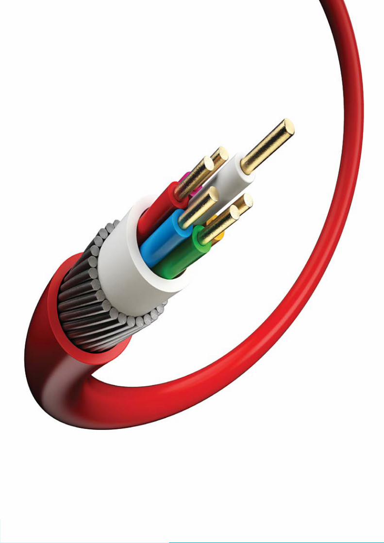
91
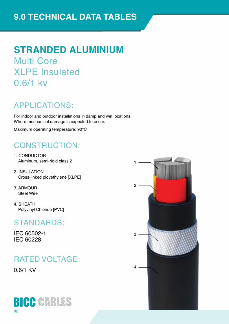
92
1
2
3
4
STRANDEDALUMINIUMMulti CoreXLPE Insulated0.6/1 kv
APPLICATIONS:
CONSTRUCTION:
STANDARDS:
RATED VOLTAGE:
INTRODUCTION9.0TECHNICALDATATABLES
For indoor and outdoor installations in damp and wet locations.Wheremechanicaldamageisexpectedtooccur.
Maximumoperatingtemperature:90°C
1. CONDUCTORAluminum, semi-rigid class 2
2. INSULATIONCross-linked ployethylene [XLPE]
3. ARMOURSteel Wire
4. SHEATHPolyvinyl Chloride [PVC]
IEC 60502-1IEC 60228
0.6/1 KV
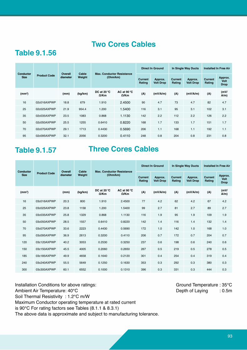
Installation Conditions for above ratings:Ambient Air Temperature: 40°CSoil Thermal Resistivity : 1.2°C m/WMaximumConductoroperatingtemperatureatratedcurrentis 90°C For rating factors see Tables (8.1.1 & 8.3.1)Theabovedataisapproximateandsubjecttomanufacturingtolerance.
Ground Temperature : 35°C Depth of Laying : 0.5m
Table 9.1.56
Table 9.1.57
ConductorSize ProductCode Overall
diameterCable Weight
Max.ConductorResistance(Ohm/km)
DirectInGround InSingleWayDucts InstalledInFreeAir
CurrentRating
Approx.VoltDrop
CurrentRating
Approx.VoltDrop
CurrentRating
Approx.VoltDrop
(mm2) (mm) (kg/km) DCat20⁰CΩ/Km
ACat90⁰CΩ/Km (A) (mV/A/m) (A) (mV/A/m) (A) (mV/
A/m)
16 02c016AXPWP 18.8 679 1.910 2.4500 90 4.7 73 4.7 82 4.7
25 02c025AXPWP 21.9 954.4 1.200 1.5400 116 3.1 95 3.1 102 3.1
35 02c035AXPWP 23.5 1083 0.868 1.1130 142 2.2 112 2.2 126 2.2
50 02c050AXPWP 25.5 1255 0.6410 0.8220 168 1.7 133 1.7 151 1.7
70 02c070AXPWP 29.1 1713 0.4430 0.5690 206 1.1 168 1.1 192 1.1
95 02c095AXPWP 32.1 2056 0.3200 0.4110 248 0.8 204 0.8 231 0.8
ConductorSize ProductCode Overall
diameterCable Weight
Max.ConductorResistance(Ohm/km)
DirectInGround InSingleWayDucts InstalledInFreeAir
CurrentRating
Approx.VoltDrop
CurrentRating
Approx.VoltDrop
CurrentRating
Approx.VoltDrop
(mm2) (mm) (kg/km) DCat20⁰CΩ/Km
ACat90⁰CΩ/Km (A) (mV/A/m) (A) (mV/A/m) (A) (mV/
A/m)
16 03c016AXPWP 20.3 800 1.910 2.4500 77 4.2 62 4.2 67 4.2
25 03c025AXPWP 23.8 1158 1.200 1.5400 99 2.7 81 2.7 89 2.7
35 03c035AXPWP 25.8 1329 0.868 1.1130 116 1.9 95 1.9 109 1.9
50 03c050AXPWP 28.5 1557 0.6410 0.8220 142 1.4 116 1.4 132 1.4
70 03c070AXPWP 33.6 2223 0.4430 0.5690 172 1.0 142 1.0 168 1.0
95 03c095AXPWP 36.9 2613 0.3200 0.4110 206 0.7 172 0.7 204 0.7
120 03c120AXPWP 40.2 3053 0.2530 0.3250 237 0.6 198 0.6 240 0.6
150 03c150AXPWP 45.5 4005 0.2060 0.2650 267 0.5 219 0.5 278 0.5
185 03c185AXPWP 49.9 4658 0.1640 0.2120 301 0.4 254 0.4 319 0.4
240 03c240AXPWP 55.5 5649 0.1250 0.1630 353 0.3 292 0.3 380 0.3
300 03c300AXPWP 60.1 6552 0.1000 0.1310 396 0.3 331 0.3 444 0.3
TwoCoresCables
Three Cores Cables
93

94
ConductorSize ProductCode Overall
diameterCable Weight
Max.ConductorResistance(Ohm/km)
DirectInGround InSingleWayDucts InstalledInFreeAir
CurrentRating
Approx.VoltDrop
CurrentRating
Approx.VoltDrop
CurrentRating
Approx.VoltDrop
(mm2) (mm) (kg/km) DCat20⁰CΩ/Km
ACat90⁰CΩ/Km (A) (mV/A/m) (A) (mV/A/m) (A) (mV/
A/m)
25 3Hc025AXPWP 25.9 1283 1.200/1.1910 1.5400/2.4500 99 2.7 81 2.7 89 2.7
35 3Hc035AXPWP 28.2 1476 0.868/1.9100 1.1130/2.4500 116 1.9 95 1.9 109 1.9
50 3Hc050AXPWP 31.5 1780 0.641/1.2000 0.8220/1.5400 142 1.4 116 1.4 132 1.4
70 3Hc070AXPWP 35.4 2418 0.443/0.8680 0.5690/1.1130 172 1.0 142 1.0 168 1.0
95 3Hc095AXPWP 39.1 2911 0.32/0.6410 0.4110/0.8220 206 0.7 172 0.7 204 0.7
120 3Hc120AXPWP 43.9 3770 0.253/0.4430 0.3250/0.5690 237 0.6 198 0.6 240 0.6
150 3Hc150AXPWP 49.5 4498 0.206/0.4430 0.2650/0.5690 267 0.5 219 0.5 278 0.5
185 3Hc185AXPWP 52.8 5197 0.164/0.3200 0.2120/0.4110 301 0.4 254 0.4 319 0.4
240 3Hc240AXPWP 60.3 6393 0.125/0.2530 0.1630/0.3250 353 0.3 292 0.3 380 0.3
300 3Hc300AXPWP 64.3 7364 0.1000/0.2060 0.1310/0.2650 396 0.3 331 0.3 444 0.3
INTRODUCTION9.0TECHNICALDATATABLES
Installation Conditions for above ratings:Ambient Air Temperature: 40°CSoil Thermal Resistivity : 1.2°C m/WMaximumConductoroperatingtemperatureatratedcurrentis 90°C For rating factors see Tables (8.1.1 & 8.3.1)Theabovedataisapproximateandsubjecttomanufacturingtolerance.
Ground Temperature : 35°C Depth of Laying : 0.5m
Table 9.1.58
Table 9.1.59
ConductorSize ProductCode Overall
diameterCable Weight
Max.ConductorResistance(Ohm/km)
DirectInGround InSingleWayDucts InstalledInFreeAir
CurrentRating
Approx.VoltDrop
CurrentRating
Approx.VoltDrop
CurrentRating
Approx.VoltDrop
(mm2) (mm) (kg/km) DCat20⁰CΩ/Km
ACat90⁰CΩ/Km (A) (mV/A/m) (A) (mV/A/m) (A) (mV/
A/m)
16 04c016AXPWP 24.1 1137 1.910 2.4500 77 4.2 62 4.2 67 4.2
25 04c025AXPWP 28.0 1410 1.200 1.5400 99 2.7 81 2.7 89 2.7
35 04c035AXPWP 28.4 1567 0.868 1.1130 116 1.9 95 1.9 109 1.9
50 04c050AXPWP 34.1 2077 0.6410 0.8220 142 1.4 116 1.4 132 1.4
70 04c070AXPWP 37.0 2633 0.4430 0.5690 172 1.0 142 1.0 168 1.0
95 04c095AXPWP 40.8 3142 0.3200 0.4110 206 0.7 172 0.7 204 0.7
120 04c120AXPWP 46.1 4117 0.2530 0.3250 237 0.6 198 0.6 240 0.6
150 04c150AXPWP 50.5 4819 0.2060 0.2650 267 0.5 219 0.5 278 0.5
185 04c185AXPWP 55.3 5636 0.1640 0.2120 301 0.4 254 0.4 319 0.4
240 04c240AXPWP 64.3 6881 0.1250 0.1630 353 0.3 292 0.3 380 0.3
300 04c300AXPWP 69.8 8060 0.1000 0.1310 396 0.3 331 0.3 444 0.3
FourCoresCablesWithReducedNeutral
FourCoresCables
95
96
All Aluminium Conductors (AAC)
Aluminium Conductor Steel Reinforced Bare (ACSR)
Copper conductors (BC)
Arial Bundel Cables (ABC)
INDEX
INTRODUCTION10.0 OVERHEADCONDUCTORS
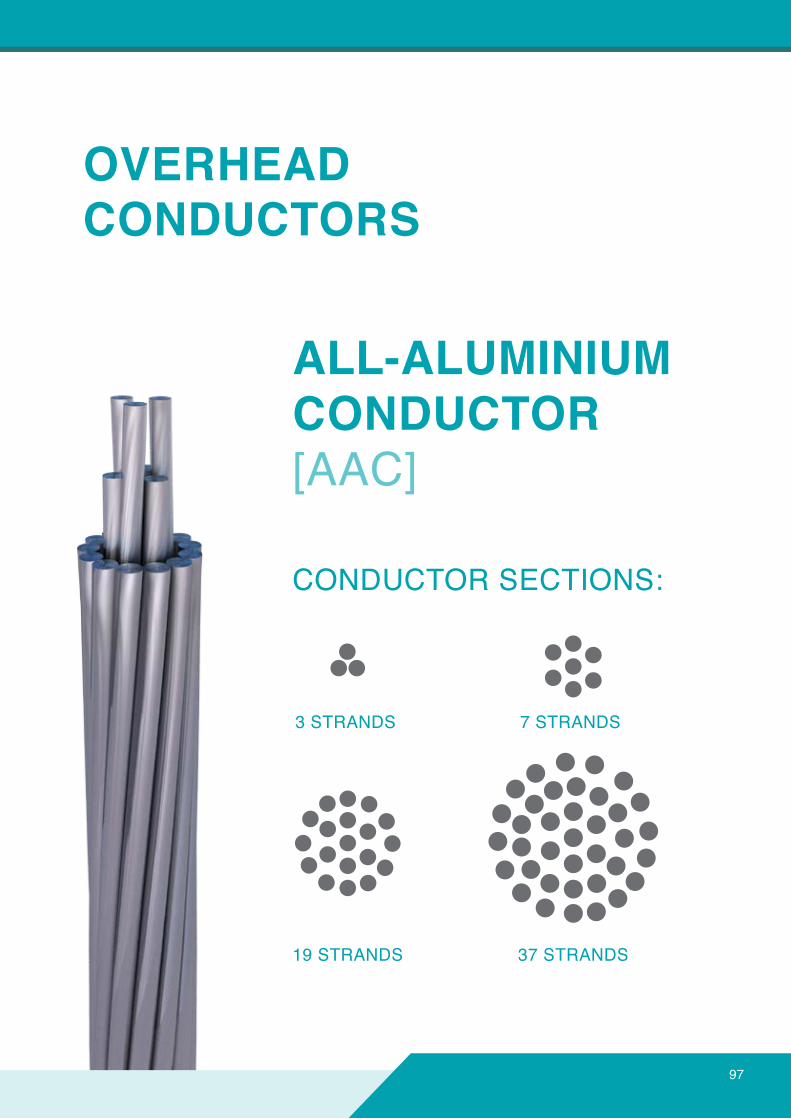
OVERHEADCONDUCTORS
ALL-ALUMINIUMCONDUCTOR[AAC]
CONDUCTOR SECTIONS:
3 STRANDS 7 STRANDS
19 STRANDS 37 STRANDS
97
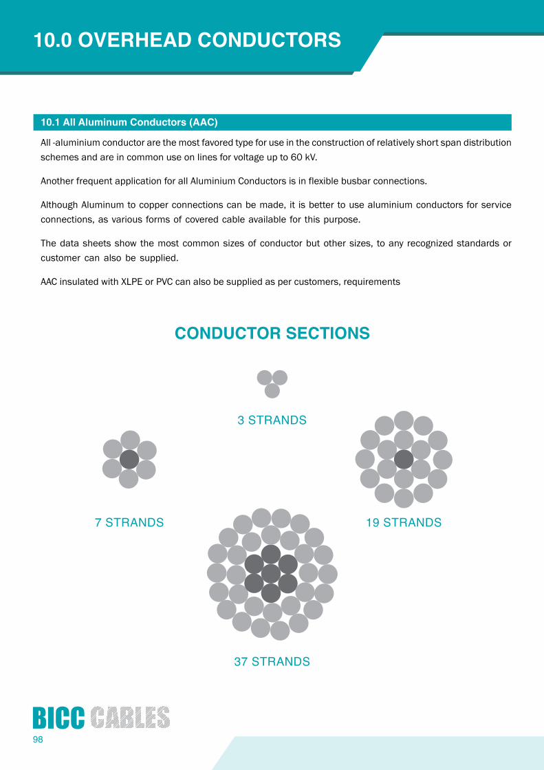
98
10.0 OVERHEADCONDUCTORS
10.1AllAluminumConductors(AAC)
All -aluminium conductor are the most favored type for use in the construction of relatively short span distribution schemes and are in common use on lines for voltage up to 60 kV.
Another frequent application for all Aluminium Conductors is in flexible busbar connections.
Although Aluminum to copper connections can be made, it is better to use aluminium conductors for service connections, as various forms of covered cable available for this purpose.
The data sheets show the most common sizes of conductor but other sizes, to any recognized standards or customer can also be supplied.
AAC insulated with XLPE or PVC can also be supplied as per customers, requirements
CONDUCTORSECTIONS
3 STRANDS
7 STRANDS 19 STRANDS
37 STRANDS
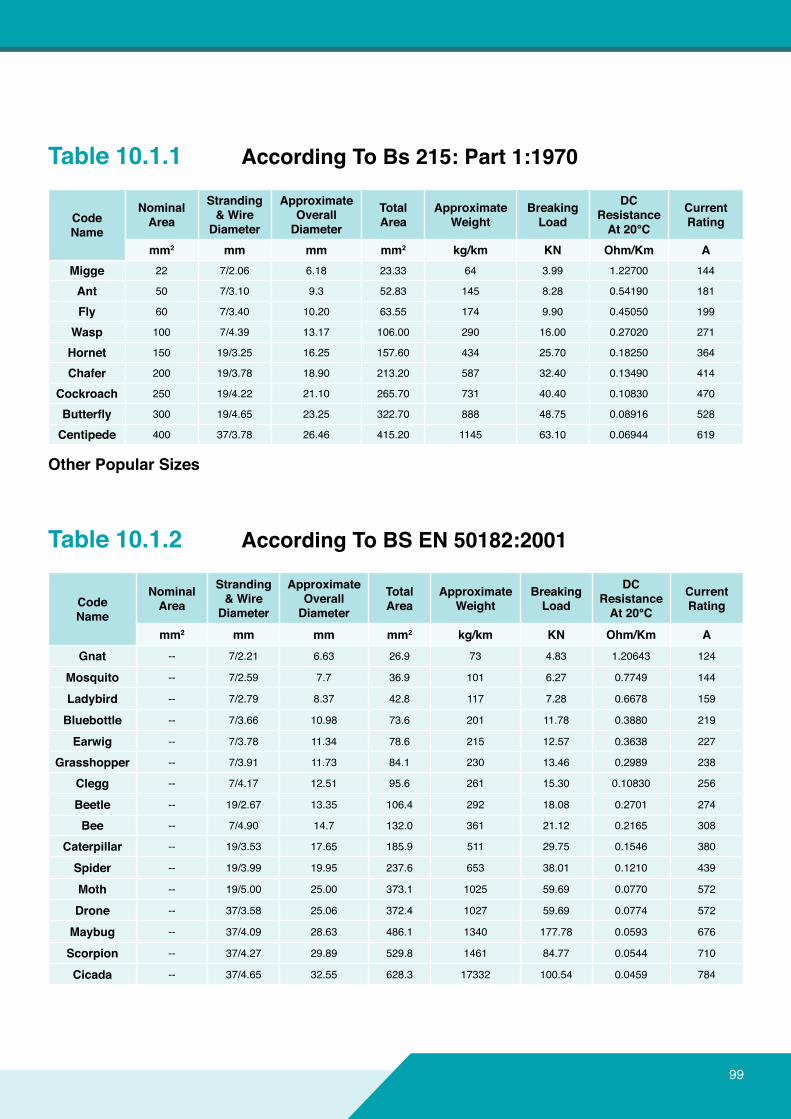
99
Table 10.1.1
Table 10.1.2
AccordingToBs215:Part1:1970
AccordingToBSEN50182:2001
OtherPopularSizes
CodeName
NominalArea
Stranding&WireDiameter
ApproximateOverall Diameter
TotalArea
ApproximateWeight
Breaking Load
DCResistanceAt20°C
CurrentRating
mm2 mm mm mm2 kg/km KN Ohm/Km AMigge 22 7/2.06 6.18 23.33 64 3.99 1.22700 144
Ant 50 7/3.10 9.3 52.83 145 8.28 0.54190 181
Fly 60 7/3.40 10.20 63.55 174 9.90 0.45050 199
Wasp 100 7/4.39 13.17 106.00 290 16.00 0.27020 271
Hornet 150 19/3.25 16.25 157.60 434 25.70 0.18250 364
Chafer 200 19/3.78 18.90 213.20 587 32.40 0.13490 414
Cockroach 250 19/4.22 21.10 265.70 731 40.40 0.10830 470
Butterfly 300 19/4.65 23.25 322.70 888 48.75 0.08916 528
Centipede 400 37/3.78 26.46 415.20 1145 63.10 0.06944 619
CodeName
NominalArea
Stranding&WireDiameter
ApproximateOverall Diameter
TotalArea
ApproximateWeight
Breaking Load
DCResistanceAt20°C
CurrentRating
mm2 mm mm mm2 kg/km KN Ohm/Km AGnat -- 7/2.21 6.63 26.9 73 4.83 1.20643 124
Mosquito -- 7/2.59 7.7 36.9 101 6.27 0.7749 144
Ladybird -- 7/2.79 8.37 42.8 117 7.28 0.6678 159
Bluebottle -- 7/3.66 10.98 73.6 201 11.78 0.3880 219
Earwig -- 7/3.78 11.34 78.6 215 12.57 0.3638 227
Grasshopper -- 7/3.91 11.73 84.1 230 13.46 0.2989 238
Clegg -- 7/4.17 12.51 95.6 261 15.30 0.10830 256
Beetle -- 19/2.67 13.35 106.4 292 18.08 0.2701 274
Bee -- 7/4.90 14.7 132.0 361 21.12 0.2165 308
Caterpillar -- 19/3.53 17.65 185.9 511 29.75 0.1546 380
Spider -- 19/3.99 19.95 237.6 653 38.01 0.1210 439
Moth -- 19/5.00 25.00 373.1 1025 59.69 0.0770 572
Drone -- 37/3.58 25.06 372.4 1027 59.69 0.0774 572
Maybug -- 37/4.09 28.63 486.1 1340 177.78 0.0593 676
Scorpion -- 37/4.27 29.89 529.8 1461 84.77 0.0544 710
Cicada -- 37/4.65 32.55 628.3 17332 100.54 0.0459 784
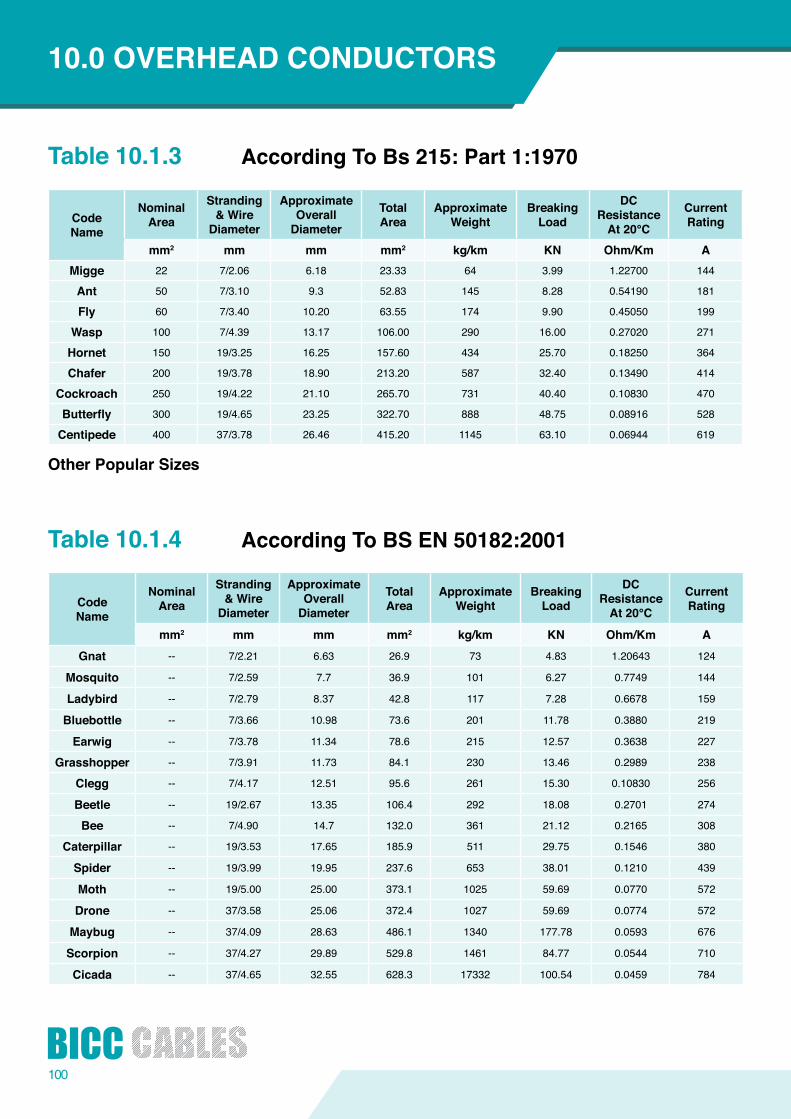
100
Table 10.1.3
Table 10.1.4
AccordingToBs215:Part1:1970
AccordingToBSEN50182:2001
OtherPopularSizes
CodeName
NominalArea
Stranding&WireDiameter
ApproximateOverall Diameter
TotalArea
ApproximateWeight
Breaking Load
DCResistanceAt20°C
CurrentRating
mm2 mm mm mm2 kg/km KN Ohm/Km AMigge 22 7/2.06 6.18 23.33 64 3.99 1.22700 144
Ant 50 7/3.10 9.3 52.83 145 8.28 0.54190 181
Fly 60 7/3.40 10.20 63.55 174 9.90 0.45050 199
Wasp 100 7/4.39 13.17 106.00 290 16.00 0.27020 271
Hornet 150 19/3.25 16.25 157.60 434 25.70 0.18250 364
Chafer 200 19/3.78 18.90 213.20 587 32.40 0.13490 414
Cockroach 250 19/4.22 21.10 265.70 731 40.40 0.10830 470
Butterfly 300 19/4.65 23.25 322.70 888 48.75 0.08916 528
Centipede 400 37/3.78 26.46 415.20 1145 63.10 0.06944 619
CodeName
NominalArea
Stranding&WireDiameter
ApproximateOverall Diameter
TotalArea
ApproximateWeight
Breaking Load
DCResistanceAt20°C
CurrentRating
mm2 mm mm mm2 kg/km KN Ohm/Km AGnat -- 7/2.21 6.63 26.9 73 4.83 1.20643 124
Mosquito -- 7/2.59 7.7 36.9 101 6.27 0.7749 144
Ladybird -- 7/2.79 8.37 42.8 117 7.28 0.6678 159
Bluebottle -- 7/3.66 10.98 73.6 201 11.78 0.3880 219
Earwig -- 7/3.78 11.34 78.6 215 12.57 0.3638 227
Grasshopper -- 7/3.91 11.73 84.1 230 13.46 0.2989 238
Clegg -- 7/4.17 12.51 95.6 261 15.30 0.10830 256
Beetle -- 19/2.67 13.35 106.4 292 18.08 0.2701 274
Bee -- 7/4.90 14.7 132.0 361 21.12 0.2165 308
Caterpillar -- 19/3.53 17.65 185.9 511 29.75 0.1546 380
Spider -- 19/3.99 19.95 237.6 653 38.01 0.1210 439
Moth -- 19/5.00 25.00 373.1 1025 59.69 0.0770 572
Drone -- 37/3.58 25.06 372.4 1027 59.69 0.0774 572
Maybug -- 37/4.09 28.63 486.1 1340 177.78 0.0593 676
Scorpion -- 37/4.27 29.89 529.8 1461 84.77 0.0544 710
Cicada -- 37/4.65 32.55 628.3 17332 100.54 0.0459 784
10.0 OVERHEADCONDUCTORS
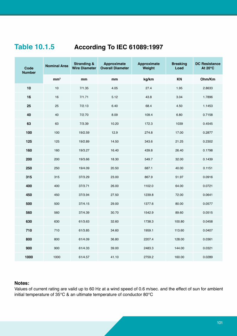
101
Table 10.1.5 AccordingToIEC61089:1997
CodeNumber
NominalArea Stranding&WireDiameter
ApproximateOverallDiameter
ApproximateWeight
Breaking Load
DCResistanceAt20°C
mm2 mm mm kg/km KN Ohm/Km
10 10 7/1.35 4.05 27.4 1.95 2.8633
16 16 7/1.71 5.12 43.8 3.04 1.7896
25 25 7/2.13 6.40 68.4 4.50 1.1453
40 40 7/2.70 8.09 109.4 6.80 0.7158
63 63 7/3.39 10.20 172.3 1039 0.4545
100 100 19/2.59 12.9 274.8 17.00 0.2877
125 125 19/2.89 14.50 343.6 21.25 0.2302
160 160 19/3.27 16.40 439.8 26.40 0.1798
200 200 19/3.66 18.30 549.7 32.00 0.1439
250 250 19/4.09 20.50 687.1 40.00 0.1151
315 315 37/3.29 23.00 867.9 51.97 0.0916
400 400 37/3.71 26.00 1102.0 64.00 0.0721
450 450 37/3.94 27.50 1239.8 72.00 0.0641
500 500 37/4.15 29.00 1377.6 80.00 0.0577
560 560 37/4.39 30.70 1542.9 89.60 0.0515
630 630 61/3.63 32.60 1738.3 100.80 0.0458
710 710 61/3.85 34.60 1959.1 113.60 0.0407
800 800 61/4.09 36.80 2207.4 128.00 0.0361
900 900 61/4.33 39.00 2483.3 144.00 0.0321
1000 1000 61/4.57 41.10 2759.2 160.00 0.0289
Notes:Values of current rating are valid up to 60 Hz at a wind speed of 0.6 m/sec. and the effect of sun for ambient initial temperature of 35°C & an ultimate temperature of conductor 80°C
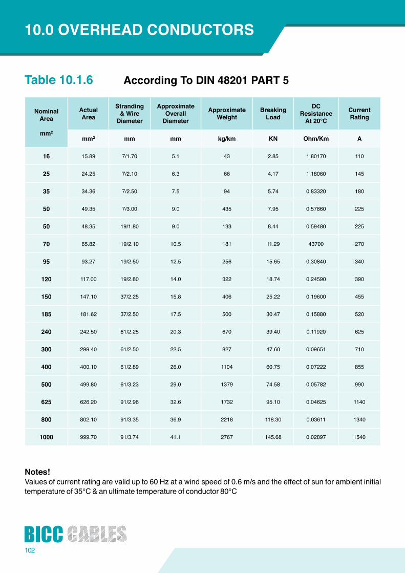
102
Table 10.1.6 AccordingToDIN48201PART5
NominalArea
mm2
ActualArea
Stranding&WireDiameter
ApproximateOverall Diameter
ApproximateWeight
Breaking Load
DCResistanceAt20°C
CurrentRating
mm2 mm mm kg/km KN Ohm/Km A
16 15.89 7/1.70 5.1 43 2.85 1.80170 110
25 24.25 7/2.10 6.3 66 4.17 1.18060 145
35 34.36 7/2.50 7.5 94 5.74 0.83320 180
50 49.35 7/3.00 9.0 435 7.95 0.57860 225
50 48.35 19/1.80 9.0 133 8.44 0.59480 225
70 65.82 19/2.10 10.5 181 11.29 43700 270
95 93.27 19/2.50 12.5 256 15.65 0.30840 340
120 117.00 19/2.80 14.0 322 18.74 0.24590 390
150 147.10 37/2.25 15.8 406 25.22 0.19600 455
185 181.62 37/2.50 17.5 500 30.47 0.15880 520
240 242.50 61/2.25 20.3 670 39.40 0.11920 625
300 299.40 61/2.50 22.5 827 47.60 0.09651 710
400 400.10 61/2.89 26.0 1104 60.75 0.07222 855
500 499.80 61/3.23 29.0 1379 74.58 0.05782 990
625 626.20 91/2.96 32.6 1732 95.10 0.04625 1140
800 802.10 91/3.35 36.9 2218 118.30 0.03611 1340
1000 999.70 91/3.74 41.1 2767 145.68 0.02897 1540
Notes!Values of current rating are valid up to 60 Hz at a wind speed of 0.6 m/s and the effect of sun for ambient initial temperature of 35°C & an ultimate temperature of conductor 80°C
10.0 OVERHEADCONDUCTORS
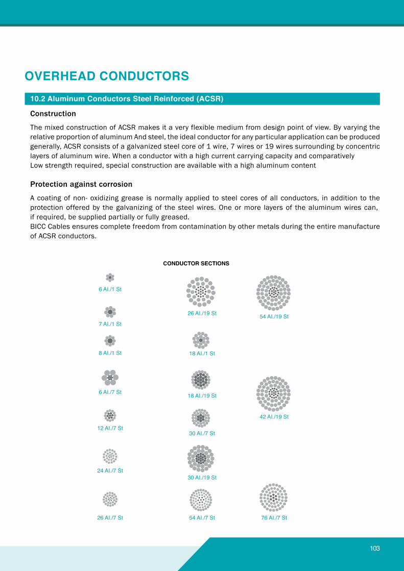
103
10.2AluminumConductorsSteelReinforced(ACSR)
Construction
The mixed construction of ACSR makes it a very flexible medium from design point of view. By varying the relative proportion of aluminum And steel, the ideal conductor for any particular application can be produced generally, ACSR consists of a galvanized steel core of 1 wire, 7 wires or 19 wires surrounding by concentric layers of aluminum wire. When a conductor with a high current carrying capacity and comparativelyLow strength required, special construction are available with a high aluminum content
Protection against corrosion
A coating of non- oxidizing grease is normally applied to steel cores of all conductors, in addition to the protection offered by the galvanizing of the steel wires. One or more layers of the aluminum wires can,if required, be supplied partially or fully greased.BICC Cables ensures complete freedom from contamination by other metals during the entire manufacture of ACSR conductors.
6 AI./1 St
26 AI./19 St
18 AI./1 St
18 AI./19 St
30 AI./7 St
30 AI./19 St
54 AI./7 St 76 AI./7 St
42 AI./19 St
54 AI./19 St
CONDUCTORSECTIONS
7 AI./1 St
8 AI./1 St
6 AI./7 St
12 AI./7 St
24 AI./7 St
26 AI./7 St
OVERHEADCONDUCTORS
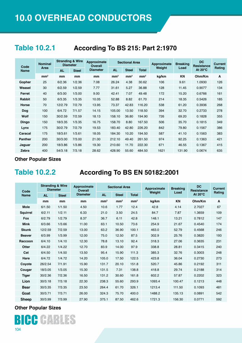
104
Table 10.2.1
Table 10.2.2
AccordingToBS215:Part2:1970
AccordingToBSEN50182:2001
OtherPopularSizes
OtherPopularSizes
CodeName
NominalArea
Stranding&WireDiameter
ApproximateOverall Diameter
SectionalArea ApproximateWeight
Breaking Load
DCResistanceAt20°C
CurrentRatingAL Steel TotalAL Steel
mm2 mm mm mm mm2 mm2 mm2 kg/km KN Ohm/Km AGopher 25 6/2.36 1/2.36 7.08 26.24 4.38 30.62 106 9.61 1.0930 126Weasel 30 6/2.59 1/2.59 7.77 31.61 5.27 36.88 128 11.45 0.9077 134Ferret 40 6/3.00 1/3.00 9.00 42.41 7.07 49.48 172 15.20 0.6766 161Rabbit 50 6/3.35 1/3.35 10.05 52.88 8.82 61.70 214 18.35 0.5426 185Horse 70 12/2.79 7/2.79 13.95 73.37 42.83 116.20 538 61.20 0.3936 268Dog 100 6/4.72 7/1.57 14.15 105.00 13.50 118.50 394 32.70 0.2733 278Wolf 150 30/2.59 7/2.59 18.13 158.10 36.80 194.90 726 69.20 0.1828 355Dingo 150 18/3.35 1/3.35 16.75 158.70 8.80 167.50 506 35.70 0.1815 349Lynx 175 30/2.79 7/2.79 19.53 183.40 42.80 226.20 842 79.80 0.1567 386
Caracal 175 18/3.61 1/3.61 18.05 184.30 10.20 194.50 587 41.10 0.1563 383Panther 200 30/3.00 7/3.00 21.00 212.10 49.40 261.50 974 92.25 0.1363 421Jaguar 200 18/3.86 1/3.86 19.30 210.60 11.70 222.30 671 46.55 0.1367 415Zebra 400 54/3.18 7/3.18 28.62 428.90 55.60 484.50 1621 131.90 0.0674 635
CodeName
Stranding&WireDiameter
ApproximateOverall Diameter
SectionalArea ApproximateWeight
Breaking Load
DCResistanceAt20°C
CurrentRating
AL Steel TotalAL Steelmm mm mm mm2 mm2 mm2 kg/km KN Ohm/Km A
Mole 6/1.50 1/1.50 4.50 10.6 1.77 12.4 42.8 4.14 2.7027 67Squirrel 6/2.11 1/2.11 6.33 21.0 3.50 24.5 84.7 7.87 1.3659 109Fox 6/2.79 1/2.79 8.37 36.7 6.11 42.8 148.1 13.21 0.7812 147Mink 6/3.66 1/3.66 11.00 63.1 10.50 73.6 254.9 21.67 0.4540 174
Skunk 12/2.59 7/2.59 13.00 63.2 36.90 100.1 463.0 52.79 0.4568 246Beaver 6/3.99 1/3.99 12.00 75.0 12.50 87.5 302.9 25.76 0.3820 193Raccoon 6/4.10 1/4.10 12.30 78.8 13.10 92.4 318.3 27.06 0.3635 231Otter 6/4.22 1/4.22 12.70 83.9 14.00 97.9 338.8 28.81 0.3415 240Cat 6/4.50 1/4.50 13.50 95.4 15.90 111.3 385.3 32.76 0.3003 248Hare 6/4.72 1/4.72 14.20 105.0 17.50 122.5 423.8 36.04 0.2730 273Coyote 26/2.54 7/1.91 15.90 131.7 20.10 151.8 520.7 45.86 0.2192 311Cougar 18/3.05 1/3.05 15.30 131.5 7.31 138.8 418.8 29.74 0.2188 314Tiger 30/2.36 7/2.36 16.50 131.2 30.60 161.8 602.2 57.87 0.2202 323
Lion 30/3.18 7/3.18 22.30 238.3 55.60 293.9 1093.4 100.47 0.1213 448
Bear 30/3.35 7/3.35 23.50 264.4 61.70 326.1 1213.4 111.50 0.1093 481
Goat 30/3.71 7/3.71 26.00 324.3 75.70 400.0 1488.2 135.13 0.0891 542
Sheep 30/3.99 7/3.99 27.90 375.1 87.50 462.6 1721.3 156.30 0.0771 592
10.0 OVERHEADCONDUCTORS
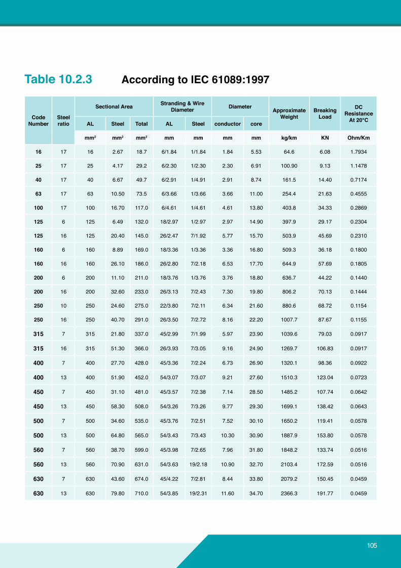
105
Table 10.2.3 AccordingtoIEC61089:1997
CodeNumber
Steelratio
SectionalArea Stranding&WireDiameter Diameter Approximate
WeightBreaking Load
DCResistanceAt20°CAL Steel Total AL Steel conductor core
mm2 mm2 mm2 mm mm mm mm kg/km KN Ohm/Km
16 17 16 2.67 18.7 6/1.84 1/1.84 1.84 5.53 64.6 6.08 1.7934
25 17 25 4.17 29.2 6/2.30 1/2.30 2.30 6.91 100.90 9.13 1.1478
40 17 40 6.67 49.7 6/2.91 1/4.91 2.91 8.74 161.5 14.40 0.7174
63 17 63 10.50 73.5 6/3.66 1/3.66 3.66 11.00 254.4 21.63 0.4555
100 17 100 16.70 117.0 6/4.61 1/4.61 4.61 13.80 403.8 34.33 0.2869
125 6 125 6.49 132.0 18/2.97 1/2.97 2.97 14.90 397.9 29.17 0.2304
125 16 125 20.40 145.0 26/2.47 7/1.92 5.77 15.70 503.9 45.69 0.2310
160 6 160 8.89 169.0 18/3.36 1/3.36 3.36 16.80 509.3 36.18 0.1800
160 16 160 26.10 186.0 26/2.80 7/2.18 6.53 17.70 644.9 57.69 0.1805
200 6 200 11.10 211.0 18/3.76 1/3.76 3.76 18.80 636.7 44.22 0.1440
200 16 200 32.60 233.0 26/3.13 7/2.43 7.30 19.80 806.2 70.13 0.1444
250 10 250 24.60 275.0 22/3.80 7/2.11 6.34 21.60 880.6 68.72 0.1154
250 16 250 40.70 291.0 26/3.50 7/2.72 8.16 22.20 1007.7 87.67 0.1155
315 7 315 21.80 337.0 45/2.99 7/1.99 5.97 23.90 1039.6 79.03 0.0917
315 16 315 51.30 366.0 26/3.93 7/3.05 9.16 24.90 1269.7 106.83 0.0917
400 7 400 27.70 428.0 45/3.36 7/2.24 6.73 26.90 1320.1 98.36 0.0922
400 13 400 51.90 452.0 54/3.07 7/3.07 9.21 27.60 1510.3 123.04 0.0723
450 7 450 31.10 481.0 45/3.57 7/2.38 7.14 28.50 1485.2 107.74 0.0642
450 13 450 58.30 508.0 54/3.26 7/3.26 9.77 29.30 1699.1 138.42 0.0643
500 7 500 34.60 535.0 45/3.76 7/2.51 7.52 30.10 1650.2 119.41 0.0578
500 13 500 64.80 565.0 54/3.43 7/3.43 10.30 30.90 1887.9 153.80 0.0578
560 7 560 38.70 599.0 45/3.98 7/2.65 7.96 31.80 1848.2 133.74 0.0516
560 13 560 70.90 631.0 54/3.63 19/2.18 10.90 32.70 2103.4 172.59 0.0516
630 7 630 43.60 674.0 45/4.22 7/2.81 8.44 33.80 2079.2 150.45 0.0459
630 13 630 79.80 710.0 54/3.85 19/2.31 11.60 34.70 2366.3 191.77 0.0459
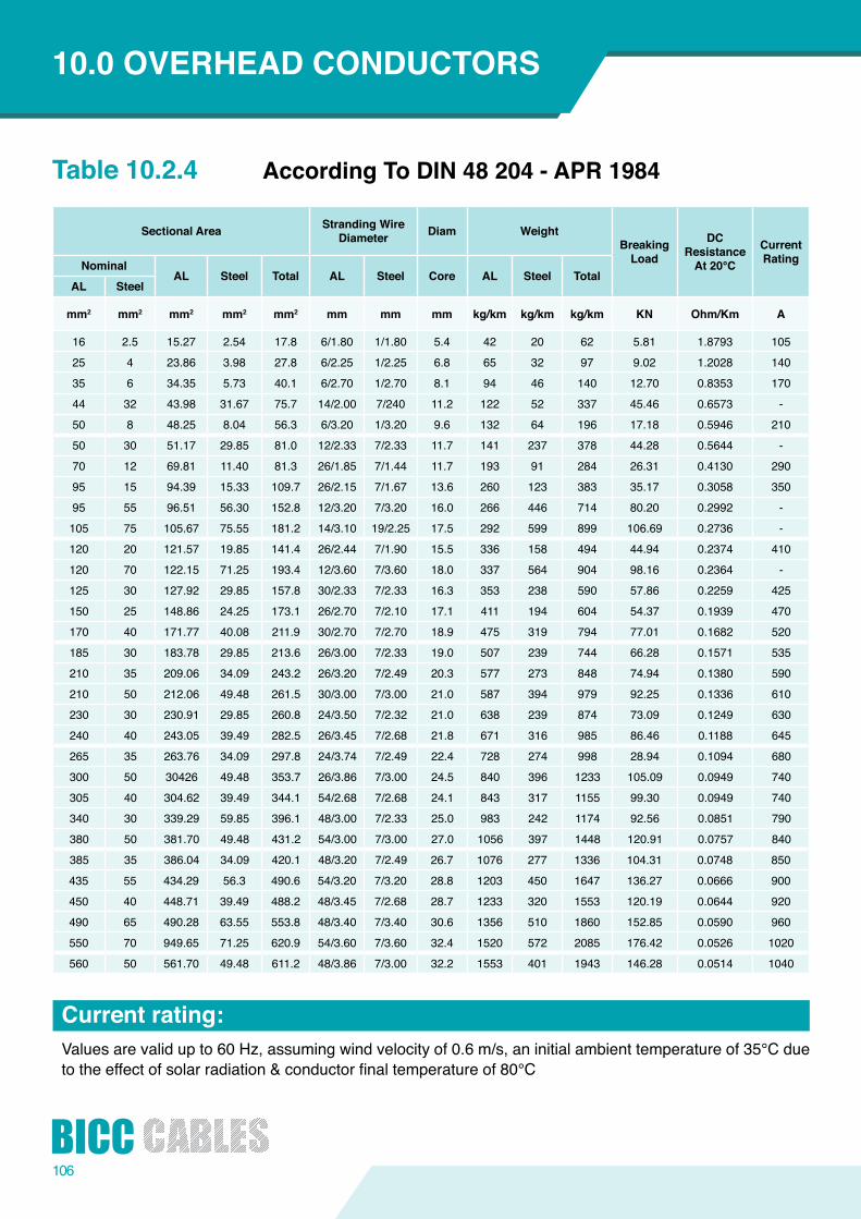
106
Table 10.2.4 AccordingToDIN48204-APR1984
SectionalArea StrandingWireDiameter Diam Weight
Breaking Load
DCResistanceAt20°C
CurrentRatingNominal
AL Steel Total AL Steel Core AL Steel TotalAL Steel
mm2 mm2 mm2 mm2 mm2 mm mm mm kg/km kg/km kg/km KN Ohm/Km A
16 2.5 15.27 2.54 17.8 6/1.80 1/1.80 5.4 42 20 62 5.81 1.8793 10525 4 23.86 3.98 27.8 6/2.25 1/2.25 6.8 65 32 97 9.02 1.2028 14035 6 34.35 5.73 40.1 6/2.70 1/2.70 8.1 94 46 140 12.70 0.8353 17044 32 43.98 31.67 75.7 14/2.00 7/240 11.2 122 52 337 45.46 0.6573 -50 8 48.25 8.04 56.3 6/3.20 1/3.20 9.6 132 64 196 17.18 0.5946 21050 30 51.17 29.85 81.0 12/2.33 7/2.33 11.7 141 237 378 44.28 0.5644 -70 12 69.81 11.40 81.3 26/1.85 7/1.44 11.7 193 91 284 26.31 0.4130 29095 15 94.39 15.33 109.7 26/2.15 7/1.67 13.6 260 123 383 35.17 0.3058 35095 55 96.51 56.30 152.8 12/3.20 7/3.20 16.0 266 446 714 80.20 0.2992 -105 75 105.67 75.55 181.2 14/3.10 19/2.25 17.5 292 599 899 106.69 0.2736 -120 20 121.57 19.85 141.4 26/2.44 7/1.90 15.5 336 158 494 44.94 0.2374 410120 70 122.15 71.25 193.4 12/3.60 7/3.60 18.0 337 564 904 98.16 0.2364 -125 30 127.92 29.85 157.8 30/2.33 7/2.33 16.3 353 238 590 57.86 0.2259 425150 25 148.86 24.25 173.1 26/2.70 7/2.10 17.1 411 194 604 54.37 0.1939 470170 40 171.77 40.08 211.9 30/2.70 7/2.70 18.9 475 319 794 77.01 0.1682 520185 30 183.78 29.85 213.6 26/3.00 7/2.33 19.0 507 239 744 66.28 0.1571 535210 35 209.06 34.09 243.2 26/3.20 7/2.49 20.3 577 273 848 74.94 0.1380 590210 50 212.06 49.48 261.5 30/3.00 7/3.00 21.0 587 394 979 92.25 0.1336 610230 30 230.91 29.85 260.8 24/3.50 7/2.32 21.0 638 239 874 73.09 0.1249 630240 40 243.05 39.49 282.5 26/3.45 7/2.68 21.8 671 316 985 86.46 0.1188 645265 35 263.76 34.09 297.8 24/3.74 7/2.49 22.4 728 274 998 28.94 0.1094 680300 50 30426 49.48 353.7 26/3.86 7/3.00 24.5 840 396 1233 105.09 0.0949 740305 40 304.62 39.49 344.1 54/2.68 7/2.68 24.1 843 317 1155 99.30 0.0949 740340 30 339.29 59.85 396.1 48/3.00 7/2.33 25.0 983 242 1174 92.56 0.0851 790380 50 381.70 49.48 431.2 54/3.00 7/3.00 27.0 1056 397 1448 120.91 0.0757 840385 35 386.04 34.09 420.1 48/3.20 7/2.49 26.7 1076 277 1336 104.31 0.0748 850435 55 434.29 56.3 490.6 54/3.20 7/3.20 28.8 1203 450 1647 136.27 0.0666 900450 40 448.71 39.49 488.2 48/3.45 7/2.68 28.7 1233 320 1553 120.19 0.0644 920490 65 490.28 63.55 553.8 48/3.40 7/3.40 30.6 1356 510 1860 152.85 0.0590 960550 70 949.65 71.25 620.9 54/3.60 7/3.60 32.4 1520 572 2085 176.42 0.0526 1020560 50 561.70 49.48 611.2 48/3.86 7/3.00 32.2 1553 401 1943 146.28 0.0514 1040
Currentrating:Values are valid up to 60 Hz, assuming wind velocity of 0.6 m/s, an initial ambient temperature of 35°C due to the effectofsolarradiation&conductorfinaltemperatureof80°C
10.0 OVERHEADCONDUCTORS
107
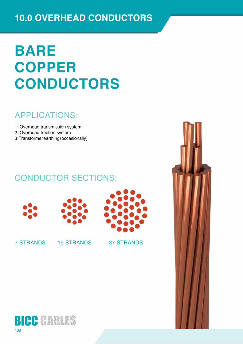
108
CONDUCTOR SECTIONS:
7 STRANDS 19 STRANDS 37 STRANDS
BARECOPPERCONDUCTORS
APPLICATIONS: 1: Overhead transmission system2: Overhead traction system3: Transformer earthing (occasionally)
10.0 OVERHEADCONDUCTORS
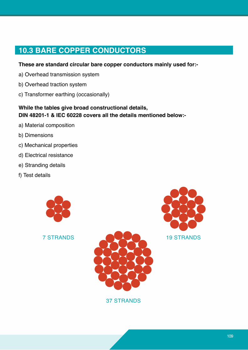
10.3BARECOPPERCONDUCTORSThesearestandardcircularbarecopperconductorsmainlyusedfor:-
a) Overhead transmission system
b) Overhead traction system
c) Transformer earthing (occasionally)
Whilethetablesgivebroadconstructionaldetails,DIN48201-1&IEC60228coversallthedetailsmentionedbelow:-
a) Material composition
b) Dimensions
c) Mechanical properties
d) Electrical resistance
e) Stranding details
f) Test details
7 STRANDS 19 STRANDS
37 STRANDS
109
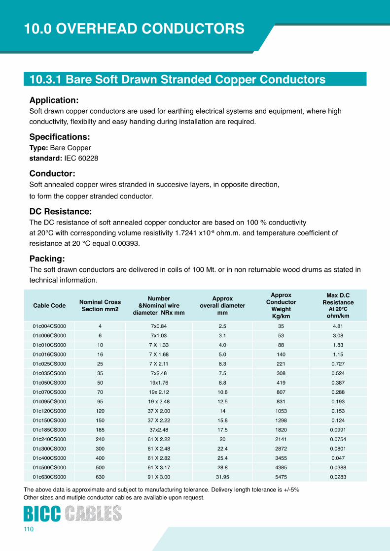
110
10.3.1BareSoftDrawnStrandedCopperConductorsApplication:Soft drawn copper conductors are used for earthing electrical systems and equipment, where high conductivity,flexibiltyandeasyhandingduringinstallationarerequired.
Specifications:Type: Bare Copperstandard: IEC 60228
Conductor:Soft annealed copper wires stranded in succesive layers, in opposite direction,to form the copper stranded conductor.
DCResistance:TheDCresistanceofsoftannealedcopperconductorarebasedon100%conductivityat20°Cwithcorrespondingvolumeresistivity1.7241x10-8ohm.m.andtemperaturecoefficientofresistance at 20 °C equal 0.00393.
Packing:The soft drawn conductors are delivered in coils of 100 Mt. or in non returnable wood drums as stated in technical information.
Cable Code NominalCrossSectionmm2
Number&Nominalwire
diameterNRxmm
Approxoveralldiameter
mm
ApproxConductorWeightKg/km
MaxD.CResistance
At20°Cohm/km
01c004CS000 4 7x0.84 2.5 35 4.81
01c006CS000 6 7x1.03 3.1 53 3.08
01c010CS000 10 7 X 1.33 4.0 88 1.83
01c016CS000 16 7 X 1.68 5.0 140 1.15
01c025CS000 25 7 X 2.11 8.3 221 0.727
01c035CS000 35 7x2.48 7.5 308 0.524
01c050CS000 50 19x1.76 8.8 419 0.387
01c070CS000 70 19x2.12 10.8 807 0.288
01c095CS000 95 19x2.48 12.5 831 0.193
01c120CS000 120 37 X 2.00 14 1053 0.153
01c150CS000 150 37 X 2.22 15.8 1298 0.124
01c185CS000 185 37x2.48 17.5 1820 0.0991
01c240CS000 240 61 X 2.22 20 2141 0.0754
01c300CS000 300 61 X 2.48 22.4 2872 0.0801
01c400CS000 400 61 X 2.82 25.4 3455 0.047
01c500CS000 500 61 X 3.17 28.8 4385 0.0388
01c630CS000 630 91 X 3.00 31.95 5475 0.0283
Theabovedataisapproximateandsubjecttomanufacturingtolerance.Deliverylengthtoleranceis+/-5%Other sizes and mutiple conductor cables are available upon request.
10.0 OVERHEADCONDUCTORS
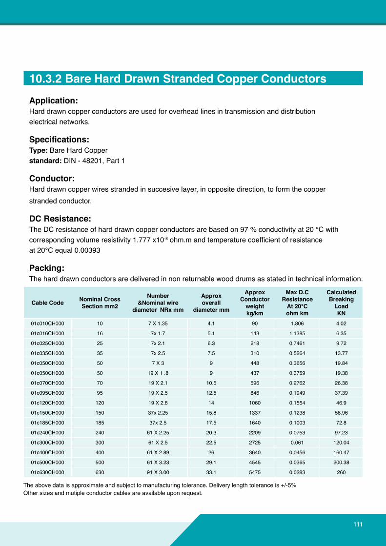
111
10.3.2BareHardDrawnStrandedCopperConductorsApplication:Hard drawn copper conductors are used for overhead lines in transmission and distributionelectrical networks.
Specifications:Type: Bare Hard Copperstandard: DIN - 48201, Part 1
Conductor:Hard drawn copper wires stranded in succesive layer, in opposite direction, to form the copperstranded conductor.
DCResistance:TheDCresistanceofharddrawncopperconductorsarebasedon97%conductivityat20°Cwithcorrespondingvolumeresistivity1.777x10-8ohm.mandtemperaturecoefficientofresistanceat 20°C equal 0.00393
Packing:The hard drawn conductors are delivered in non returnable wood drums as stated in technical information.
Cable Code NominalCrossSectionmm2
Number&Nominalwire
diameterNRxmm
Approxoverall
diametermm
ApproxConductorweightkg/km
MaxD.CResistanceAt20°Cohmkm
CalculatedBreaking LoadKN
01c010CH000 10 7 X 1.35 4.1 90 1.806 4.02
01c016CH000 16 7x1.7 5.1 143 1.1385 6.35
01c025CH000 25 7x2.1 6.3 218 0.7461 9.72
01c035CH000 35 7x2.5 7.5 310 0.5264 13.77
01c050CH000 50 7 X 3 9 448 0.3656 19.84
01c050CH000 50 19 X 1 .8 9 437 0.3759 19.38
01c070CH000 70 19 X 2.1 10.5 596 0.2762 26.38
01c095CH000 95 19 X 2.5 12.5 846 0.1949 37.39
01c120CH000 120 19 X 2.8 14 1060 0.1554 46.9
01c150CH000 150 37x2.25 15.8 1337 0.1238 58.96
01c185CH000 185 37x2.5 17.5 1640 0.1003 72.8
01c240CH000 240 61 X 2.25 20.3 2209 0.0753 97.23
01c300CH000 300 61 X 2.5 22.5 2725 0.061 120.04
01c400CH000 400 61 X 2.89 26 3640 0.0456 160.47
01c500CH000 500 61 X 3.23 29.1 4545 0.0365 200.38
01c630CH000 630 91 X 3.00 33.1 5475 0.0283 260
Theabovedataisapproximateandsubjecttomanufacturingtolerance.Deliverylengthtoleranceis+/-5%Other sizes and mutiple conductor cables are available upon request.
112
11.0GLOSSARY
AAbrasionResistance:Ability of a material or cable to resist surface wear.A.C.ResistanceThe total resistance offered by a device to alternating current circuit due to inductive and capacitive effects,as well as the direct current resistance.ActivecurrentIn an alternating current, a component in phase with the voltage. The working component as distinguished from the idle or wattles component.AerialcableA cable suspended in the air on poles or otheroverhead structure.Alternatingcurrent(A.C.)An electric current that continually reverses its direction giving a repetitiveplusandminuswaveformatfixedintervals.AlternatingvoltageThe voltage developed across a resistance or impedance throughwhichalternatingcurrentisflowing.AmbienttemperatureThe romal temperature within a given area.AmericanwiregaugeA standard used in the determination of the physical size of a conductordeterminedbyitscircularmilarea.Usuallyexpressedas AWG. Also referred to as Brown and Sharpe (B&S) wire gauge.AmpacityThemaximumcurrentaninsulatedwireorcablecansafely\carrywithoutexceedingeithertheinsulationorjacketmateriallimitations (Same as current carrying capacity).AmpereTheunitcurrent.Oneampereisthecurrentflowingthroughoneohm of resistance at one volt potential.AnnealTosubjectto high heat wit subsequent cooling. When annealing copper, the act of softening the metal by means of heat to render it less brittle expressedinHertz.AreaofconductorThe size of conductor cross-section measured in circular mils, square inches, etc.ArmorA braid or wrapping of metal, usually steel, used for mechanical protection.ArmoredcableA cable having a metallic covering for protection against mechanical injury.ASAMThe American Society for Testing and MaterialsAWGAbbreviation for American Wire Gauge.
BBareconductorA conductor having no covering.A conductor with no coatingor cladding on the copper.BeddingA layer of material applied to a cable immediatelybelow the armoring.BinderA spirally served tape or thread used for holding assembled cable components in place awaiting subsequent manufacturing operations.BraidAfibrousormetallicgroupoffilaments interwovenincylindricalform to form a covering over one or more wires.BreakdownofinsulationFailureofaninsulatedconductorresultingaflowofcurrentthrough the insulation. It may be caused by the application of excessvoltageorbydefectsordecay.BreakdownvoltageThe voltage at which the insulation between two conductors breaks down.BunchedStrandAny number of conductor strands twisted together in one direction with the same lay length.Buried CableA cable installed directly in the ground without use of under ground conduit. Also called "direct burial cable".
CCableA group of individually insulated conductors in twisted or parallel configuration,withorwithoutanoverallcovering.CablingThe act of twisting together two or more insulated components by machine to form a cable.CapacitanceStorage of electrically separated charges between two plates having different potentials.The value depends on the surface area of the plates and the distance and material between them.The quantity of electricity held statically in a capacitor or an insulated conductor.Colour CodeAcoloursystemforcircuitidentificationbyuseofsolidcolours,tracers, braids, surface printing, etc.CompositecableA cable consisting of two or more different types or sizes of wires.
113
ConcentricityIn a wire or cable, the measurement of the location of the center of the conductor with respect to the geometric center of the circular insulation.ConcentricStrandingA group of wires twisted so as to contain a center core with one or more distinct layers of spirally wrapped, wires laid overall.ConductanceThe ability of a conductor to carry electric current.It is the reciprocal of resistance and is measured in Mhos.ConductivityA term used in describing the capability of a material to carry an electricalcharge.Usuallyexpressedasapercentageofcopperconductivitycopperbeingonehundred(100%)percent.ConductorAny material capable of transferring electrical charge easily.CoreIn cables, a term used to denote a component or assembly of components, over which other materials are applied, such as additional components, shield, sheath, or armor.Cross-SectionalAreaThe area of the cut surface of an object cut at right angles to the length of the object.CurrentTherateofflowofelectricityinacircuit,measuredinamperes.CurrentCarryingCapacityThe maximum current an insulated conductor or cable cancontinuously carry without exceeding its temperature rating.It is also called ampacity.Current,Direct(D.C.)Electricalcurrentwhoseelectronsflowinonedirectiononly;it may be constant or pulsating as long as their movementis in the same direction.CycleThe complete sequence of alternation or reversal of alternation orreversaloftheflowofanalternatingelectriccurrent.(See Hertz)
DielectrictestA test in which a higher than the rated voltage is applied for a specifiedtimetodeterminetheadequacyoftheinsulationundernormal conditions.DirectcapacitanceThe capacitance measured directly from conductor to conductor through a single insulation layer.DirectionofLayThe direction, either clockwise or counterclockwise,ofaconductororgroupofconductorswhenlookingaxiallydown a cable length.Drawingin The manufacturing of wire , pulling the metal through a die or seriesdiesforreductionofdiametertoaspecifiedsize.
DD.C.Abbreviation for "Direct Current".DielectricConstant(K)The ratio of the capacitance of a capacitor (or consoles) with dielectric between the electrodes to the capacitance with air is between the electrodes.Also called permittivity and specificinductive capacity.DielectricStrengthThe voltage which an insulation can withstand before breakdown occurs.Usuallyexpressedasavoltagegradient(such as volts per mil).
EEccentricityLike concentricity, a measure of the center of a conductor's locationwithrespecttothecircularcross-sectionoftheinsulation;expressedasapercentageofcenterdisplacementofonecirclewithin the other.EmbossingAmeansofidentificationorletteringusingheatandorpressureto leave raised lettering on the sheath material of the cable.ExtrusionThe process of continuously forcing a plastic or elastomer and a conductor core through a die, thereby applying a continuous coating of insulation or jacket to the core or conductor.
FFaradA unit of electrical capacity.Filler(1)Amaterialusedinthecabletofilllargeintersticesbetween
electricalcomponents;(2) A substance, often inert, added to a compound to improve
propertied and / or decrease cost.FlameResistanceAbilityofthematerialtoextinguishflameoncethesourceofheatis removed.FlexibleCableA cable containing one or more cores, each formed of a group of wires, the diameters of the wires, the diameters of the wires beingsufficientlysmall toaffordflexibility.FlexibilityThe ease with which a cable may be bent.FrequencyNumber of times an alternating current reverses itself in one second.ExpressedinHertz(Hz),whichisonecyclepersecond.
114
11.0GLOSSARY
JJacketA material covering over a wire insulation or an assembly of components.Anoverall jacketonacomplexcablegrouping isalso often referred to as a sheath
KKilohertz1.000 Hertz (cycles per second}.KilovoltA term denoting 1000 volts.KilowattA term denoting 1000 watts.
HHarnessAn arrangement of wires and cables, usually with many breakouts, which have been tied together or pulled into a rubber or plastic sheath, used to interconnect electric circuit.HeatResistanceAbility of a substance to maintain physical chemical and electrical integrityunderspecifiedtemperatureconditions.HenryUnit of inductance such that the induced voltage in volts is numerically equal to the rate of change of current inamperes per second.Hertz(Hz)A term replacing cycles-per seconds as a unit of frequency.HighTemperaturewireandcableThose electrical wires and cable having thermal operating characteristics of 125°C and higher.HzAbbreviation for Hertz.
IICEA
AInsulated Cable Engineers Association (formerly IPCEA)IECInternational Electro technical Commission, Similar to the ISO in structure and scope.IEEEInstitute of Electrical and Electronic Engineers.impedanceThetotaloppositionthatacircuitofferstotheflowofalternatingcurrent or any other varying current ata particular frequency. It is a combination of resistance R and reactance X,measured in ohms.impulse(Orpulse}A surge of unidirectional polarity.inducedCurrentAn electric current set up in a circuit by interacting electrical fieldsacurrentcausedbyelectromagneticinduction.inductanceThe property of a circuit element that opposes a change in currentflow,thuscausingcurrentchangetolagbehindvoltagechanges. It is measured in Henrys.inductionThe phenomenon of a voltage, magnetic field or electrostaticcharge being produced in an object by lines of force from the
GGaugeA term used to denote physical size.
LLayDirectionThe direction in which the strands of a conductor run over the top of the conductor as they recede from and observer looking along theaxisoftheconductor.LeakageCurrentTheundesirableflowofcurrent throughorover thesurfaceofinsulation.
MMegaohmOne million ohms.MhoThe unit of conductivity. The reciprocal of an ohm.MhzMegahertz (one million cycles per second).
source of such fields.InductivecouplingCrosstalkresultingfromtheactionoftheelectromagneticfieldofone conductor on the other.insulationA non-conductive material usually surrounding or separating two conductive materials. Often called the dielectric in a radio frequency cable.insulationResistanceThat property of an insulating material which resists electrical current flow through the insulating material when a potentialdifference is applied.InsulationThicknessThe wall thickness of the applied insulation.InterferenceAny undesired electrical signal induced into a conductor by electrical or electromagnetic means (Noise).ISOInternational Standards Organization.
115
OOhmUnit of resistance such that a constant current of one Ampere produces a force of one volt.OverallDiameterFinished diameter over wire or cable.OverCurrentTheCurrentwhichcausesandexcessivetemperaturerisein a conductor.OverloadCapacityThemaximumlevelofcurrent,voltage,orpowerwhichadevicecan withstand before it is damaged.
RRatedTemperatureThe maximum temperature at which an electric componentcanoperate for extendedperiodswithout lossof its operatingproperties.RatedVoltageThe maximum voltage at which an electric component canoperateforextendedperiodswithoutdegradationofperformanceor safety hazard.ReactanceTheoppositionoffered to theflowofalternatingcurrentby theinductance or capacitance of a component or circuit.ResistanceIn D.C. circuits, the opposition a material offers to current, measured in ohms. In A.C. Circuits, resistance is the real component of impedance, and may be higher than the value measured at D.C.RoundConductorA conductor whose cross-section is substantially circular.
NNextNear end crosstalk
QQuadA four- wire unit of insulated conductors.
PPolyesterPolyethylene terephthalate which is used extensively in theproduction of a high strength moisture resistant film used ascable core wrapping material.PolyethyleneA family of insulating materials derived from polymerization of ethylene gas. They are basically pure hydrocarbon resins, with excellent dielectric properties.Polyvinlychloride(PVC).A thermoplastic material composed of polymers of vinyl chloride which may be rigid or elastomeric, depending on specificformulation.PowerFactorThe ratio of resistance to impedance. The ratio of the actual power of an alternating current to apparent power. Mathematically, the cosine of the angle between the voltage applied and the current resulting.PropagationtimeTime required for an electrical wave to travel between two points ona transmission line.
MoistureResistanceThe ability of a material to resist absorbing moisture from the air or when immersed in water.Multi-ConductorMore than one conductor within a single cable.MutualinductanceThe ratio of voltage induced in one conductor to the time rate of current change in the se arate conductor causing this induction.MylarDuPonttrademarkforpolyethyleneterephthalate(polyester)filmused in the form of a tape.
PulseA current or voltage which changes abruptly from one value to anotherandbacktotheoriginalvalueinafinitelengthoftime.Pulse CableA type of coaxial cable constructed to transmit repeated highvoltage pulses without degradation.
SSheathThematerial,usuallyanextrudedplasticorelastomer,appliedoutermost to a wire or cable. Very often referred to asa jacket.ShieldA metallic layer around an insulated conductor or group of conductors to prevent electrostatic or electromagnetic interference between the enclosed wires and external fields.This shield can be braided or served wires, foil wrap, foil backed tape, a metallic tube , or conductors, the shielding effectiveness isinproportiontotheamountofcoverage,usuallyexpressedinpercentage.Shield CoverageThe physical area of a cable that is actually covered by the shielding material and is expressed in percentage.SignalCurrent used to convey information, either digital, analogue, audio or video.
116
11.0GLOSSARY
VVelocityofPropagationThe speed of an electric signal down a length of cable compared to speed in free space expressed as a percentage. It is thereciprocal of the square root of the dielectric constant of the cable insulation.
TTemperatureRatingThemaximumtemperatureatwhichinsulatingmaterialmaybeused in continuous operation without loss of its basic properties.TensilestrengthA term denoting the greatest longitudinal tensile stress
a substance can bear without mechanical failure.Thermal
RatingThemaximumand/orminimumtemperatureatwhichamaterialwill perform its functions without undue degration .ThermalShockA test to determine the ability of a material to withstand heat and cold by subjecting it to rapid and wide change in temperature.TinnedCopperTin coating over copper to aid in soldering and inhibit corrosion.TinnedwireCopper wire that has been coated with a layer of tin or solder to simplify soldering.
WWattA unit of electrical power. One watt is equivalent to the power generated by one ampere of current under a pressure of one volt in a D.C. circuit.
Single cableA cable designed to carry current of usually less than one ampere per conductor.SolidConductorA conductor consisting of a single wire.SparkTestA test designed to locate imperfections (usually pin- holes) in a wire insulation by application of an electrical potential across the material for a short period of time while the wire is drawn through anelectrodefieldwithoneendofthewiregrounded.StrandedconductorA conductor composed of individual groups of wires twisted together to form an entire unit.StrandLaylengthA distance of advance of on strand of a spirally stranded conductor,inoneturn,measuredaxially.
Volt(potentialdifference}A unit of electrical pressure. One volt is the amount of pressure that will cause one ampere of current in one ohm of resistance.VoltageThe term most often used in place of electromotive force, potential, potential difference, or voltage drop, to designate electricpressurethatexistsbetweentwopointsandiscapableofproducingaflowofcurrentwhenacircuitisconnectedbetweenthe two points.VoltageDropThe amount of voltage loss between two power in a circuit.VoltageRatingThe highest voltage that may be continuously applied to a wire or cordinconformancewithstandardsorspecifications.VolumeReceptivityThe electrical resistance between opposite face of a 1 cm cube ofinsulatingmaterialcommonlyexpressedinohms/centimeter.

117117
Weofferbestservicestartingfromcustomer'sinquirytilltheendofthedelivery.

ConnectingTheFuture