Embed Size (px)
Citation preview
10 Heat Switches
K. Lankford*
Introduction
Heat switches, known also as thermal switches, are devices that switch as needed between roles as good thermal conductors and good thermal insulators. When one is installed in the heat-conduction path between a warm, heat-producing compo- nent and a heat sink, the change in thermal conductance it affords can control the temperature of the component. Heat switches can passively control the tempera- ture of warm electronics or instrumentation without the use of thermostats and heaters, thereby reducing power requirements as well as the need for heater con- trol circuitry and software.
Cryogenic applications use heat switches to minimize heat loads on cooling sys- tems by disconnecting components when cooling is not required or disconnecting redundant refrigerators that are not providing cooling because they have failed or have been tumed off. In general, cryogenic systems include different types of heat switches than the ones found in applications closer to room temperature.
Heat switches differ from thermostats; the latter control heaters by opening or closing electrical circuits at a given temperature, while heat switches open, close, or vary heat-conduction paths. Heat switches thus function similarly to diode or variable-conductance heat pipes; however, they achieve temperature control by modulating a conduction path rather than a two-phase flow process.
Most heat switches that operate in normal spacecraft temperature ranges are passive devices that automatically self-regulate their conductance rather than react to signals received from a controller. The control they exercise is characterized by a variable adjustment of conductance between "on" and "off' values. The time constant of heat switches is usually short enough to handle rapid fluctuations in power, yet well enough damped by thermal capacitance and mechanical character- istics to avoid overshooting desired temperatures. The name "heat switch" is therefore somewhat misleading because these devices afford a more complex con- trol than the simple on/off function provided by a switch.
This chapter provides an overview of several types of heat switch, including par- affin heat switches and cryogenic heat switches. Other heat-switch designs have been proposed and/or prototyped, including designs for magnetostrictive, electro- lytic, and electrostatic switches, as well as mechanical switches actuated by elec- tric motor or liquid-to-gas phase change.
Although the concept of heat switches was first devised in the early 1960s for use on the Mariner mission to the moon, their practical development is still rela- tively new. Switches based on more recent paraffin-based technology will fly on the Propulsive Small Expendable Deployer System (ProSEDS) tether experiment mission in late 2002, and some additional heat switches are currently in the base- line design for the Jet Propulsion Laboratory (JPL) Mars '03 Rovers. Recent
*Starsys Research Corporation, Boulder, Colorado.
353
354 Heat Switches
development efforts have focused on reducing mass and increasing reliability to make switches more attractive to spacecraft programs. As heritage and experience are gained, heat switches may find increased use. Until a larger experience base is established, however, analysts must consider the risks associated with such a new technology.
Heat-Switch Applications
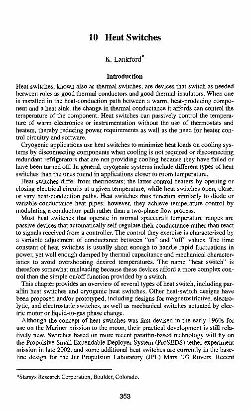
Thermal Control of Individual Components A typical application of a heat switch to control the temperature of an individual component is shown in Fig. 10.1. Here, a heat switch is mounted between an instru- ment or electronics box and a cold sink, such as a spacecraft structural panel or radi- ator. The heat switch controls the temperature to a set point selected when the switch is manufactured. When the temperatta'e of the electronics box rises above the set- point temperature, the switch conductance increases, allowing the excess heat to be transferred through the switch to the radiator and out to space. As the box cools, its temperature drops below the set-point temperature, causing the switch conductance to decrease. At the lower conductance level, the instrument is kept warm by its own heat or a low level of heater power. A heat switch can thus maintain the temperature of electronics or instrumentation within a comfortable range despite fluctuations in component heat load or variations in cold-sink temperature.
System Applications Heat switches could serve as the basis for an entire spacecraft thermal-control sys- tem, but such an application would require a shift in philosophy beginning in the early stages of the design process. In many cases, compelling reasons might jus- tify this shift, but designers could find the lack of an extensive flight history a dif- ficult barrier to overcome in making the transition to this new technology.
Examination of a typical conventional thermal design reveals why heat switches could be desirable as the basis for a spacecraft thermal-control system. As shown in the design examples of Chapter 3, the industry standard for spacecraft thermal control involves connecting internal heat-producing components to external radia- tor surfaces through either heat pipes or spacecraft structure. Radiators are then sized so that, in the worst-case hot mission environment and worst-case heat dissi- pation of the components, they still run cold enough to keep all components below
Fig. 10.1. Heat-switch application.
Heat-Switch Integration 355
their upper temperature limits. Heaters keep the hardware above lower tempera- ture limits when the system is in a low-power state or when it experiences worst- case cold mission environments.
The biggest advantage of the conventional approach to spacecraft thermal design is that it efficiently tailors the thermal-control system to specific hardware characteristics and mission environments of a particular spacecraft. However, this advantage also highlights a weakness, because the conventional approach is not very robust and entails a great deal of analysis, one-of-a-kind manufacturing, and testing. Thermal switches, on the other hand (along with other emerging technolo- gies, such as electrochromic surface finishes and capillary pumped loops), open the possibility of a new approach that could dramatically reduce the amount of analysis and testing required to produce a thermal-control system for a particular satellite. Such an approach would use the tremendous control range of heat switches, capillary pumped loops, and electrochromics to produce a generic ther- mal control system capable of maintaining acceptable temperatures for a wide range of equipment complements in a wide range of thermal environments.
As an example, standard north and south heat-pipe panels for geosynchronous communication satellites could be sized to reject 3000 W of heat at a maximum temperature of 30°C. Payload and bus electronics boxes could be mounted to this standard heat sink with thermal switches that couple the boxes to the radiator only when box temperature exceeds a particular value, such as 40°C. The boxes them- selves would have a low-emittance finish and low-emittance cable wraps so that the only significant heat-transfer path would be the connection between the ther- mal switch and the radiator panel. Even if the payload were turned off entirely, only a small amount of heater power would be required to keep each of the elec- tronics boxes warm, since the switches would decouple the boxes from the radia- tor when the former were cold. For each new satellite, bus and payload electronics boxes could be mounted to the panel according to simple design rules that specify parameters such as maximum allowable box power per square centimeter, maxi- mum total power per panel, and maximum power per heat switch. In cases where the thermal switch or radiator system provides enough "dynamic range," detailed thermal analyses and some thermal balance testing might be eliminated.
Heat-Switch Integration
In general, heat switches can control spacecraft component temperatures either from a location between an insulated spacecraft structure and an external radiator or from between the components themselves and the structure of the spacecraft. These two options lead to somewhat different switch operating modes.
Heat Switches Mounted between Structure and Radiator
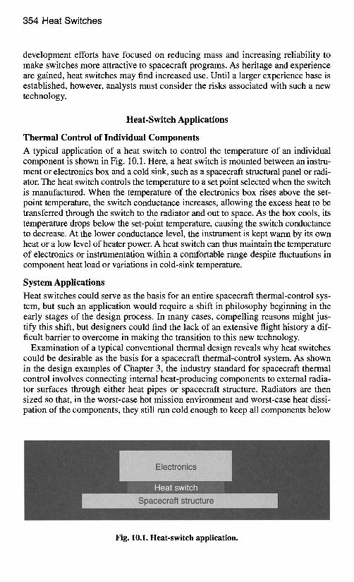
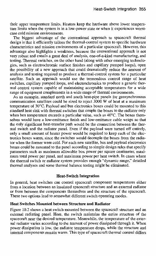
Figure 10.2 shows a heat switch mounted between the spacecraft structure and an external radiating panel. Here, the switch maintains the entire structure of the spacecraft near the desired temperature. Meanwhile, the temperature of the exter- nal radiator varies according to the amount of power dissipated through it. When power dissipation is low, the radiator temperature drops, while the structure and internal components remain warm. This type of spacecraft thermal control differs
356 Heat Switches
Fig. 10.2. Heat switch between spacecraft structure and radiator.
substantially from the more traditional type, where radiator temperatures follow the bulk temperature of the spacecraft structure. The heat switch passively controls the temperature of the structure and therefore the internal components (electron- ics, batteries, and instrument packages) by self-regulating the thermal conduc- tance through the switch. When a large amount of heat is produced, the switch adjusts itself to a high conductance. When little or no heat is produced, the switch adjusts itself to a lower conductance. Similarly, when the spacecraft goes into eclipse or changes its orientation, the heat switch adjusts itself to maintain the level of conductance needed to keep the structure at the desired temperature.
One important advantage to this approach over conventional thermal control is that radiator area can be oversized without affecting the spacecraft temperature. Excess radiator area reduces the temperature of the radiator itself but has no effect on the temperature of internal components. Radiators can be designed quickly and easily with robust margins to cover degradation of surface coatings, eclipses, changes in orientation, varying distances to the sun, changing view factors as a result of deployment of nearby solar panels or antennas, and other considerations.
Heat Switches Mounted between Components and Structure
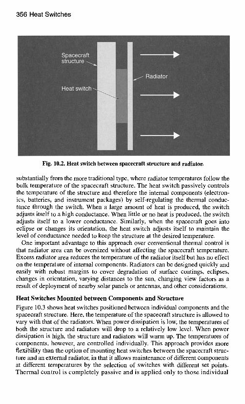
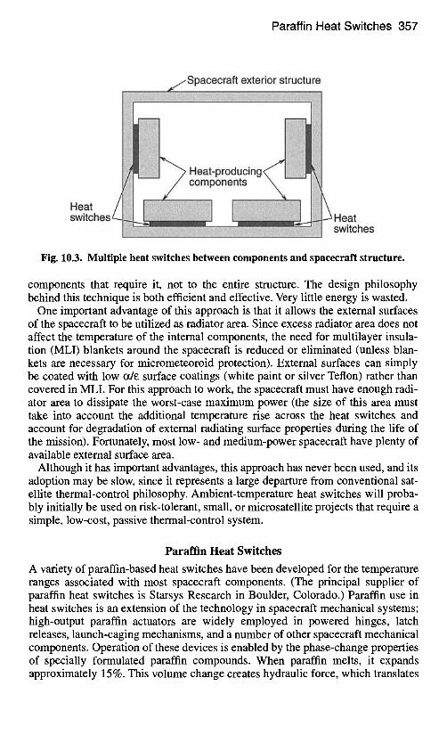
Figure 10.3 shows heat switches positioned between individual components and the spacecraft structure. Here, the temperature of the spacecraft structure is allowed to vary with that of the radiators. When power dissipation is low, the temperatures of both the structure and radiators will drop to a relatively low level. When power dissipation is high, the structure and radiators will warm up. The temperatures of components, however, are controlled individually. This approach provides more flexibility than the option of mounting heat switches between the spacecraft struc- ture and an external radiator, in that it allows maintenance of different components at different temperatures by the selection of switches with different set points. Thermal control is completely passive and is applied only to those individual
Paraffin Heat Switches 357
Spacecraft exterior structure
Heat'producin! components
Heat Heat switches
Fig. 10.3. Multiple heat switches between components and spacecraft structure.
components that require it, not to the entire structure. The design philosophy behind this technique is both efficient and effective. Very little energy is wasted.
One important advantage of this approach is that it allows the external surfaces of the spacecraft to be utilized as radiator area. Since excess radiator area does not affect the temperature of the internal components, the need for multilayer insula- tion (MLI) blankets around the spacecraft is reduced or eliminated (unless blan- kets are necessary for micrometeoroid protection). External surfaces can simply be coated with low ~/e surface coatings (white paint or silver Teflon) rather than covered in MLI. For this approach to work, the spacecraft must have enough radi- ator area to dissipate the worst-case maximum power (the size of this area must take into account the additional temperature rise across the heat switches and account for degradation of external radiating surface properties during the life of the mission). Fortunately, most low- and medium-power spacecraft have plenty of available external surface area.
Although it has important advantages, this approach has never been used, and its adoption may be slow, since it represents a large departure from conventional sat- ellite thermal-control philosophy. Ambient-temperature heat switches will proba- bly initially be used on risk-tolerant, small, or microsatellite projects that require a simple, low-cost, passive thermal-control system.
Paraffin Heat Switches
A variety of paraffin-based heat switches have been developed for the temperature ranges associated with most spacecraft components. (The principal supplier of paraffin heat switches is Starsys Research in Boulder, Colorado.) Paraffin use in heat switches is an extension of the technology in spacecraft mechanical systems; high-output paraffin actuators are widely employed in powered hinges, latch releases, launch-caging mechanisms, and a number of other spacecraft mechanical components. Operation of these devices is enabled by the phase-change properties of specially formulated paraffin compounds. When paraffin melts, it expands approximately 15%. This volume change creates hydraulic force, which translates
358 Heat Switches
into movement. In a paraffin heat switch, this movement brings two thermally conductive surfaces in contact, creating a path through which heat readily flows.
A significant amount of heat is associated with the phase change of paraffin from solid to liquid. This property gives paraffin heat switches a thermal capaci- tance that enhances their thermal-control capabilities. Typically, when the switch is controlling the temperature near its set point, the paraffin is partially frozen and partially melted. In this state, a large spike in energy is required to move the tem- perature away from the paraffin melting point because a sharp rise in heat output is first absorbed in the melting of the paraffin (see Chapter 11, "Phase-Change Mate- rials"). This behavior has the effect of damping the response, allowing the switch to respond in a smooth, controlled fashion, with no cycling in response to a change in heat load because the system is overdamped. The resulting control is therefore gentle and robust. Paraffin heat switches typically respond to a step change in power on the order of a minute.
The paraffin must be refined and synthesized to meet specific requirements. Dif- ferent types melt at different temperatures, depending on the number of carbon atoms in the paraffin chain (see the items n-undecane through n-octacosane listed in Table 1 of Chapter 11). This variety of melting points allows the analyst to tai- lor the switch set-point temperature to the application. The range of available tem- peratures is -95 to +86°C with increments approximately every 10°C.
Pedestal Heat Switch
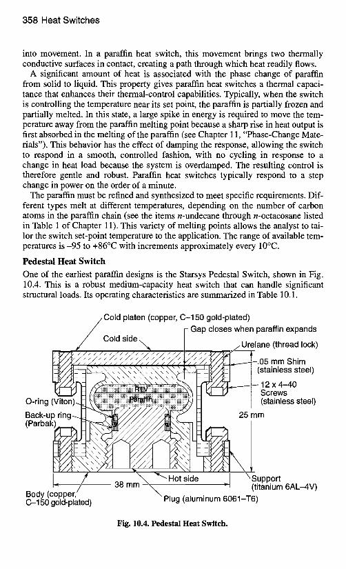
One of the earliest paraffin designs is the Starsys Pedestal Switch, shown in Fig. 10.4. This is a robust medium-capacity heat switch that can handle significant structural loads. Its operating characteristics are summarized in Table 10.1.
/ C o l d platen (copper, C-150 gold-plated) / I- Gap closes when paraffin expands
Cold side / " ~ / /Urelane (thread lock) !~ ~/~/~S ./~. S ./~.~ S ./~. S ~/~ S ~/~ S ~/~.~ ~ S / ~ / ' ~ ~L.05 mm Shim ~'[I--~-t3~'~'~ ~'~" ~"~ \ \ \ \ \ \ \ \ \ \~~iJF~-~il~h -IF/Jl--I I (stainless steel) -v--//~ ~ . . < ~ ~ ~ ~'~ ~,,-v-//~ L 12 x a_An ~" "l/J ~ ~~iiiii~ili~!!!!!!i!!!~!~!!!!!!~!!! !!!!!! !!!!!!!!!!!!!!!!! H ~" " ~ Screwss T M
• • i!iliIi~iiiiilliiilii~ ............... :"~iiiiiiiiiiililiiillilliiiiiiiiiil!lii!itli!iiii!i inl
Back-up ring-.~" ~ ~ ~ 25 mm ( P a r b a k ~
f " /X ". i" ~" Hot~ide ~ '~//~1 "~Su""ort !: / / --I (tit~'ium6AL-4V)
Body (copper, \ . , Plug taluminum 6061 T6) C-150 gold-plated)
Fig. 10.4. Pedestal Heat Switch.
Paraffin Heat Switches 359
Table 10.1. Starsys Pedestal Switch Characteristics
Characteristic Value
• Conductance ratio 100:1
Maximum conductance 0.73 W/°C
Minimum conductance 0.0075 W/°C
Mass 100 g
Diameter 38.1 mm
Height 25.4 mm
In the Pedestal switch, a central bellows chamber contains paraffin. When the switch is "open," a small gap (nominally 0.05 mm) separates the central bellows chamber and a cold platen above it. In space, a high vacuum is present in the gap; when the paraffin is cool and the gap is open, the only path for a heat-conduction leak is one that goes through the switch's outer support structure, which is made from an effective insulating material. Radiation also "leaks" heat across the gap, but this effect is small compared to conduction through the support. When the hot side of the switch is heated (by heat dissipation from the electronics), the paraffin melts and expands the bellows, closing the gap between the cold platen and the bellows chamber. This action creates a good conduction path through the copper bellows and across the contact interface.
The switch provides self-regulating variable conductance. Higher temperatures lead to a larger percentage of melted paraffin and higher pressure at the interface. Contact conductance at the interface is dependent on the pressure applied. Thus when the heat load increases, the contact conductance increases, which tends to bring the temperature back down.
Diaphragm Thin Plate Heat Switch
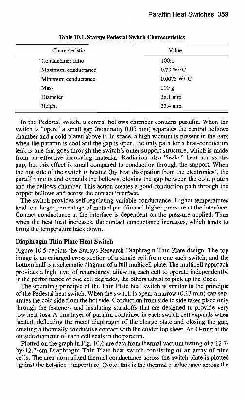
Figure 10.5 depicts the Starsys Research Diaphragm Thin Plate design. The top image is an enlarged cross section of a single cell from one such switch, and the bottom half is a schematic diagram of a full multicell plate. The multicell approach provides a high level of redundancy, allowing each cell to operate independently. If the performance of one cell degrades, the others adjust to pick up the slack.
The operating principle of the Thin Plate heat switch is similar to the principle of the Pedestal heat switch. When the switch is open, a narrow (0.13 mm) gap sep- arates the cold side from the hot side. Conduction from side to side takes place only through the fasteners and insulating standoffs that are designed to provide very low heat loss. A thin layer of paraffin contained in each switch cell expands when heated, deflecting the metal diaphragm of the charge plate and closing the gap, creating a thermally conductive contact with the colder top sheet. An O-ring at the outside diameter of each cell seals in the paraffin.
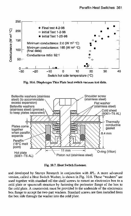
Plotted on the graph in Fig. 10.6 are data from thermal vacuum testing of a 12.7- by-12.7-cm Diaphragm Thin Plate heat switch consisting of an array of nine cells. The area-normalized thermal conductance across the switch plate is plotted against the hot-side temperature. (Note: this is the thermal conductance across the
360 Heat Switches
Cross section of a single cell
/ Screws (SST) / Plug / Paraffin /O-r ing (Viton)
, l / / l~~~ l /~ /~"~~ '~ '~ .u '~ "h"~ / \ \~4 . . ` k ' ~ / l ~ , , , ~ , . ~ ultem
a \ k { I / Cold sheet
Gap between plates (.13 mm nominal) (alum)
Multiple cell assembly (9 cells)
Instrument/electronics
Paraffin cells,
Plug to routing socket
• ~ Reject heat V
Fig. 10.5. Starsys Diaphragm Thin Plate heat switch.
switch plate itself and does not include the thermal resistance at the mounting interfaces to adjacent components or spacecraft structure.
Heat-Switch Fasteners
The Starsys Research High Performance Heat Switch Fastener is shown in Fig. 10.7. The concept for this switch was proposed by the Naval Research Laboratory
Paraffin Heat Switches 361
250
200 - o
E ~ 150 - tO t-- t~ 100 - tO
" o c -
O 5 0 -
0 -30
i I I I I I e Final test 4-2-98
Initial Test 1-2-98 • Initial Test 1-25-98 •
O
Minimum conductance: 2.0 (W m 2 °C) • O
Minimum conductance: 185 (W m 2 °C) • (final data) Conductance ratio: 92:1 0
I <>~= I 1 ,,~!£ I t -20 -10 0 10 20 30
Switch hot side temperature (°C)
Fig. 10.6. Diaphragm Thin Plate heat switch vacuum test data.
40
Belleville washers (stainless steel) (to accommodate k / / excess expansion) ~ I A
Belleville washers ~ I/ " (stainless steel) (preload \ \ ~ to keep plates separated) ~,_
Plates come $ ~ ~ ~ ~ together }~ \ \ l ~ ' [ I when p a r a f f i ~ i ~ expands ) ~ ~ ~ ~ ~ l
Paraffin f ( ~ ~ ~ 1 ~ (18°C melt $ ~ ~ ~ ] /~ . point) X \ \ ~j "~
Hot plate (8081-T6 AL)
.. Shoulder screw /11 I ~ (stainless steel)
I / I Flat washer / 7 I . ~ ' (stainless steel)
/ ~ ~ J / / C o l d sheet / ~-,, '~l,,e~// ~./ (8061-T8 AL)
/ 1 ~ " ~ ~ ~ / / ~ / / ~ - - ~ - Thermally ~ / ~ r / = ~ . ~ . conductive
ii iii!iJ~ k t ~ ~ ~ ~ ~ g a s e
/ / / ~ j ~ . ~ ~ ~ ~ ~ 8.4 mm
/ I ~ - ~ 11mm -' O-ring (Viton) Piston nut (stainless steel)
Fig. 10.7. Heat Switch Fastener.
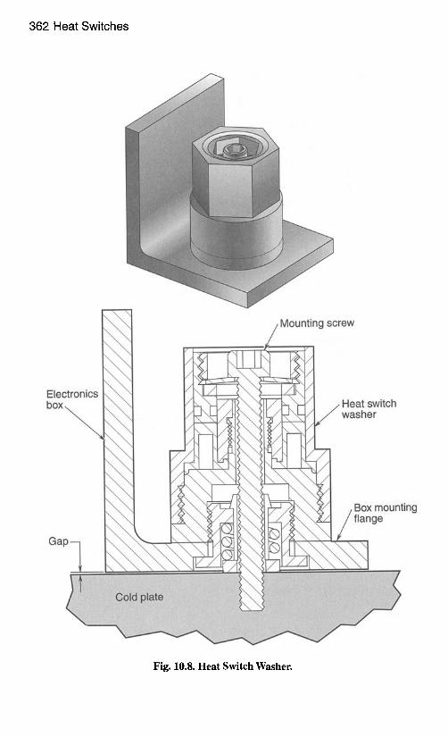
and developed by Starsys Research in conjunction with JPL. A more advanced version, called a Heat Switch Washer, is shown in Fig. 10.8. These "washers" are used together with standard off-the-shelf screws to mount an electronics box to a cold plate or spacecraft structure by fastening the perimeter flange of the box to the cold plate. A countersink must be provided in the underside of the electronics box flange to accept the two-part washers. Standard screws are then installed from the box side through the washer into the cold plate.
362 Heat Switches
Mounting screw
Electronics box Heat switch
washer
Gap- Box mounting flange
Fig. 10.8. Heat Switch Washer.
Paraffin Heat Switches 363
Each washer is a miniature actuator. When the electronics get too warm, the washers actuate to physically bring the electronics box in contact with the cold sink. When the electronics are too cool, the spring-loaded washers push the box away from the cold plate, creating a small gap. The gap creates good thermal iso- lation, which keeps the electronics from becoming too cold. The maximum rela- tive movement is small, on the order of 0.2 mm. The concept is different from the principle behind the Pedestal Heat Switch and the Diaphragm Thin Plate Heat Switch, where there is no relative movement between the heat source and heat sink. The Heat Switch Washer approach has an advantage in that it can provide better maximum conductance with less mass and is very easy to integrate with a typical electronics box.
As in other designs, the paraffin can modulate the amount of force it generates to pull the box onto the cold plate. With this ability to adjust contact pressure, the washer serves as a variable-conductance device that self-adjusts the level of con- ductance to maintain the warm-side temperature of the box near the set-point tem- perature of the switch. This modulation of contact pressure also means that no "on/off cycling" is required to maintain temperatures. Instead, the box is always in contact with the cold plate, and the switch continuously makes very minute adjust- ments to regulate the contact pressure. Actually, if the switch is ever in full open mode with a true gap between surfaces, it is operating outside its intended range, and the electronics are likely too cold.
The total contact surface area can be tailored to achieve desired results. For example, with high-power electronics, the box can be designed for full face con- tact to achieve better conductance rather than contact only around the perimeter flange. The spacing of fasteners also has an effect on conductance. Close spacing results in better closed-switch conductance but poorer open-switch isolation. More generous spacing results in better open-switch isolation but poorer closed- switch conductance.
The mass penalty associated with Heat Switch Washers is relatively small. Each will typically add 3-5 g over a standard fastener. However, the number of fasten- ers required and stiffness of the mounting surfaces play an important role in the thermal performance of the design. Many applications will need a larger number of fasteners and a stiffer mounting flange than would otherwise be necessary for purely structural support. Applications must be evaluated on a case-by-case basis.
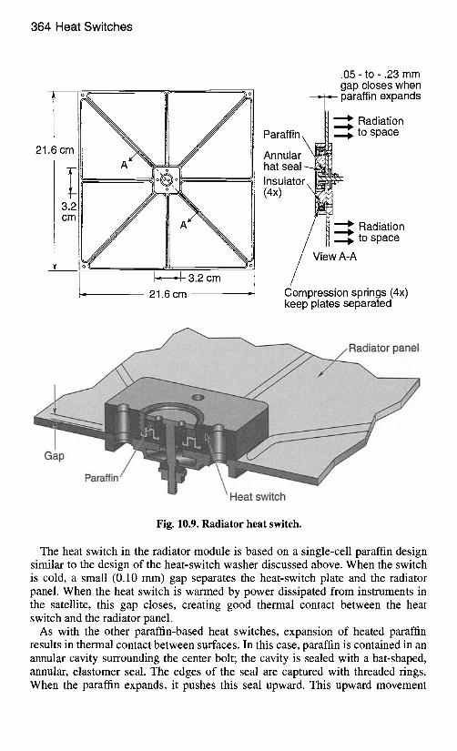
Radiator Module with Integral Heat Switch A radiator panel module that mounts to a spacecraft exterior via a heat switch is shown in Fig. 10.9. The top portion of the figure shows a front view of the 21.6- by-21.6-cm radiator and a cross section of the 3.2-by-3.2-cm heat switch. The lower part of the figure shows a three-dimensional cross section of the heat switch. In the latter image, the radiating surface points downward and the uppermost sur- face of the switch itself is the heat-transfer interface with the spacecraft. (This mounting interface is also the warm side of the switch during normal operation.) The capacity of this particular module is about 10 W, which would be suitable for thermal control of a microsat or small instrument. Using a large number of such modules to reject the waste heat from a larger satellite would provide massive redundancy and high system reliability.
364 Heat Switches
l o c
21.6 cm
3.2 c m
I '
-~ 21.6 cm ~,
.05 - to - .23 mm gap closes when
~ paraffin expands
Radiation Paraffin\ N to space
Annular kl~ , hat seal - - ~ Insulator, Ii~ (4x) " ~
Radiation to space
iew A-A
Compression springs (4x) keep plates separated
panel
Gap
Paraffin
Heat switch
Fig. 10.9. Radiator heat switch.
The heat switch in the radiator module is based on a single-cell paraffin design similar to the design of the heat-switch washer discussed above. When the switch is cold, a small (0.10 mm) gap separates the heat-switch plate and the radiator panel. When the heat switch is warmed by power dissipated from instruments in the satellite, this gap closes, creating good thermal contact between the heat switch and the radiator panel.
As with the other paraffin-based heat switches, expansion of heated paraffin results in thermal contact between surfaces. In this case, paraffin is contained in an annular cavity surrounding the center bolt; the cavity is sealed with a hat-shaped, annular, elastomer seal. The edges of the seal are captured with threaded rings. When the paraffin expands, it pushes this seal upward. This upward movement
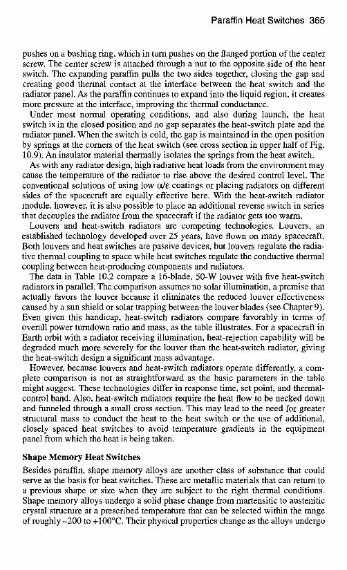
Paraffin Heat Switches 365
pushes on a bushing ring, which in turn pushes on the flanged portion of the center screw. The center screw is attached through a nut to the opposite side of the heat switch. The expanding paraffin pulls the two sides together, closing the gap and creating good thermal contact at the interface between the heat switch and the radiator panel. As the paraffin continues to expand into the liquid region, it creates more pressure at the interface, improving the thermal conductance.
Under most normal operating conditions, and also during launch, the heat switch is in the closed position and no gap separates the heat-switch plate and the radiator panel. When the switch is cold, the gap is maintained in the open position by springs at the corners of the heat switch (see cross section in upper half of Fig. 10.9). An insulator material thermally isolates the springs from the heat switch.
As with any radiator design, high radiative heat loads from the environment may cause the temperature of the radiator to rise above the desired control level. The conventional solutions of using low oCe coatings or placing radiators on different sides of the spacecraft are equally effective here. With the heat-switch radiator module, however, it is also possible to place an additional reverse switch in series that decouples the radiator from the spacecraft if the radiator gets too warm.
Louvers and heat-switch radiators are competing technologies. Louvers, an established technology developed over 25 years, have flown on many spacecraft. Both louvers and heat switches are passive devices, but louvers regulate the radia- tive thermal coupling to space while heat switches regulate the conductive thermal coupling between heat-producing components and radiators.
The data in Table 10.2 compare a 16-blade, 50-W louver with five heat-switch radiators in parallel. The comparison assumes no solar illumination, a premise that actually favors the louver because it eliminates the reduced louver effectiveness caused by a sun shield or solar trapping between the louver blades (see Chapter 9). Even given this handicap, heat-switch radiators compare favorably in terms of overall power turndown ratio and mass, as the table illustrates. For a spacecraft in Earth orbit with a radiator receiving illumination, heat-rejection capability will be degraded much more severely for the louver than the heat-switch radiator, giving the heat-switch design a significant mass advantage.
However, because louvers and heat-switch radiators operate differently, a com- plete comparison is not as straightforward as the basic parameters in the table might suggest. These technologies differ in response time, set point, and thermal- control band. Also, heat-switch radiators require the heat flow to be necked down and funneled through a small cross section. This may lead to the need for greater structural mass to conduct the heat to the heat switch or the use of additional, closely spaced heat switches to avoid temperature gradients in the equipment panel from which the heat is being taken.
Shape Memory Heat Switches Besides paraffin, shape memory alloys are another class of substance that could serve as the basis for heat switches. These are metallic materials that can return to a previous shape or size when they are subject to the right thermal conditions. Shape memory alloys undergo a solid phase change from martensitic to austenitic crystal structure at a prescribed temperature that can be selected within the range of roughly -200 to + 100°C. Their physical properties change as the alloys undergo
366 Heat Switches
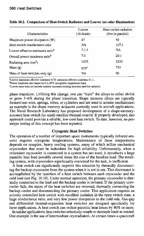
Table 10.2. Comparison of Heat-Switch Radiators and Louver (no solar illumination)
Louver Heat-switch radiators Characteristics (16-blade) (five in parallel)
Maximum power dissipation (W) Heat-switch conductance ratio
Louver effective emittance ratio a
Overall power turndown ratio b
Radiating area (cm 2)
Mass (g)
Mass of heat switches only (g)
47 50 NA 107:1 7.1:1 NA
7:1 20:1
1425 2330
875 c 733
NA 90
aLouver maximum effective emittance 0.78, minimum effective emittance 0.11. bpower turndown ratio based on 0 to 20°C acceptable temperature band. CLouver mass does not include radiator (assumes existing structure used for radiator).
phase transition. Utilizing this change, one can "train" the alloys to either shrink or grow 3-6% during the phase transition. Shape memory alloys are typically formed into wire, springs, tubes, or cylinders and are used to actuate mechanisms; an example is the shape memory actuators currently used in aircraft applications. The Naval Research Laboratory has proposed development of a shape-memory- actuated heat switch for small-satellite thermal control. If properly developed, this approach could provide a reliable, low-cost heat switch. To date, however, no pro- totype testing of this concept has been reported.
Cryogenic Heat Switches The operation of a number of important space instruments (typically infrared sen- sors) requires cryogenic temperatures. Maintenance of these temperatures depends on complex, heavy cooling systems, many of which utilize mechanical cryocoolers that must be redundant for high reliability. Unfortunately, when a redundant cryocooler is connected to a system but not used, it introduces a large parasitic heat load possibly several times the size of the baseline load. The result- ing system, with cryocoolers significantly oversized for the task, is inefficient.
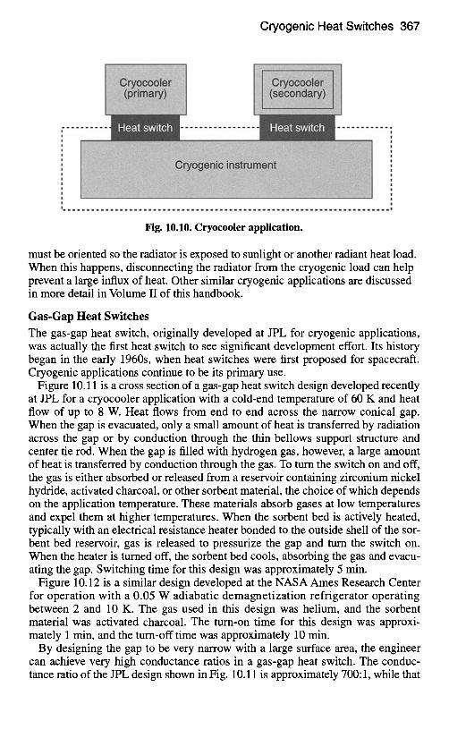
A heat switch can significantly improve this situation by thermally disconnect- ing the backup cryocooler from the system when it is not in use. This disconnect is accomplished by the insertion of a heat switch between each cryocooler and the cold load (see Fig. 10.10). Under normal operation, the primary cryocooler is ther- mally connected to the load and the backup cooler is isolated. If the primary cryo- cooler fails, the states of the heat switches are reversed, thermally connecting the backup cooler and disconnecting the primary cooler. This application requires an actively controlled heat switch with excellent isolation in the open switch state, a large conductance ratio, and very low power dissipation to the cold side. Gas-gap and differential thermal-expansion heat switches are designed specifically for these applications. A heat switch can reduce parasitic heat losses by 80% or more.
In similar applications, heat switches selectively couple or decouple loads as needed. One example is the use of intermediate cryoradiators. At certain times a spacecraft
Cryogenic Heat Switches 367
- - - !
m |
! m
| m
m m m u !
m m
m m
m m m |
m m
m m
! !
m
Fig. 10.10. Cryocooler application.
must be oriented so the radiator is exposed to sunlight or another radiant heat load. When this happens, disconnecting the radiator from the cryogenic load can help prevent a large influx of heat. Other similar cryogenic applications are discussed in more detail in Volume II of this handbook.
Gas-Gap Heat Switches The gas-gap heat switch, originally developed at JPL for cryogenic applications, was actually the first heat switch to see significant development effort. Its history began in the early 1960s, when heat switches were first proposed for spacecraft. Cryogenic applications continue to be its primary use.
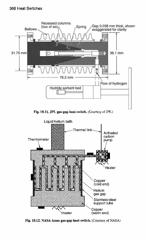
Figure 10.11 is a cross section of a gas-gap heat switch design developed recently at JPL for a cryocooler application with a cold-end temperature of 60 K and heat flow of up to 8 W. Heat flows from end to end across the narrow conical gap. When the gap is evacuated, only a small amount of heat is transferred by radiation across the gap or by conduction through the thin bellows support structure and center tie rod. When the gap is filled with hydrogen gas, however, a large amount of heat is transferred by conduction through the gas. To turn the switch on and off, the gas is either absorbed or released from a reservoir containing zirconium nickel hydride, activated charcoal, or other sorbent material, the choice of which depends on the application temperature. These materials absorb gases at low temperatures and expel them at higher temperatures. When the sorbent bed is actively heated, typically with an electrical resistance heater bonded to the outside shell of the sor- bent bed reservoir, gas is released to pressurize the gap and turn the switch on. When theheater is turned off, the sorbent bed cools, absorbing the gas and evacu- ating the gap. Switching time for this design was approximately 5 min.
Figure 10.12 is a similar design developed at the NASA Ames Research Center for operation with a 0.05 W adiabatic demagnetization refrigerator operating between 2 and 10 K. The gas used in this design was helium, and the sorbent material was activated charcoal. The turn-on time for this design was approxi- mately 1 min, and the turn-off time was approximately 10 min.
By designing the gap to be very narrow with a large surface area, the engineer can achieve very high conductance ratios in a gas-gap heat switch. The conduc- tance ratio of the JPL design shown in Fig. 10.11 is approximately 700:1, while that
368 Heat Switches
31.75 mm
Recessed columns . . . . . mm thick, shown
.=d for clarity
38.1 mm
I Hydride sorbent bed D
I I Flow of hydrogen
Fig. 10.11. JPL gas-gap heat switch. (Courtesy of JPL)
Liquid helium bath
Thermometer
Activated carbon pump
Heater
Heater
" Copper (cold end)
\ Helium gas gap
\ Stainless-steel support tube
Copper (warm end)
Fig. 10.12. NASA Ames gas-gap heat switch. (Courtesy of NASA)
Cryogenic Heat Switches 369
of the Ames design (Fig. 10.12) is 1300:1. Ratios of up to 2500:1 have been reported for more elaborate designs that utilize greater surface area. A variation of this design, also developed at Ames, used liquid helium (He II) in the gap instead of gas. This design showed a conductance ratio of 6900:1 with the cold-end tem- perature near 2 K.
Disadvantages of the gas-gap approach include slow switching times (5 min to 1 h), high cost, reliability concerns, and high mass requirements. Some concerns are related to manufacturing: obtaining the very narrow gaps needed for high performance requires very fight machining tolerances, and the hermetic seal requires a weld of high integrity. These factors lead to a high construction cost and reliability concerns. Another concern is the life of the sorbent materials and the ability to reuse them.
Differential Thermal Expansion Heat Switches
Differential thermal expansion heat switches utilize the difference in coefficient of thermal expansion (CTE) of two different materials to make or break physical contact at an interface. One part essentially shrinks more than the other as a result of a change in temperature. This is a simple, straightforward approach that can produce a very reliable and robust design.
One difficulty with this approach is that CTE of most materials is very small, typically measured in millionths of a unit length per degree. Consequently, either the temperature difference creating the actuation or the physical size of the parts must be large in order to achieve actuation distances that are significantly greater than the machining and assembly tolerances encountered in manufacturing the switch. Fortunately, cryogenically cooled components typically use a switch to decouple themselves from much warmer components on the spacecraft. Because of the large temperature differences encountered, the use of differential CTE heat switches in cryogenic applications makes good sense.
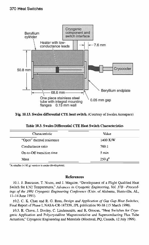
Figure 10.13 shows a relatively unique design from Swales Aerospace. This device will passively switch between "on" and "off" operating modes. With the addition of the heater to the center tube, the switch may be actively turned off, which greatly reduces the transition time from on to off (without the heater, the cryogenic component is warmed to open the gap and turn the switch off). Applica- tion of power to the heater results in the development of a large temperature gradi- ent in the center tube. The tube expands as it heats up, creating a gap between the beryllium cylinder and beryllium endplate. In a vacuum, conduction across this gap is virtually eliminated, and the switch provides excellent thermal isolation (i.e., the "off" mode). Once the beryllium endplate reaches a predetermined tem- perature (one that is between the spacecraft and the cryogenic component operat- ing temperatures and is adjustable based on the gap dimensions at assembly), the center tube is expanded sufficiently so that the switch will remain in the off condi- tion with no added heater power. To transition the switch from off to on, the beryllium endplate is cooled with the cryocooler (heater off). This causes the center tube to contract more than the beryllium endplate and cylinder, bringing the cylinder and endplate into contact, closing the gap, and putting the switch into the "on" (i.e., thermally conducting) mode. This design has a good conductance ratio, a high open switch resistance, and a fairly short transition time from the on state to the off state, as shown in Table 10.3.
370 Heat Switches
Beryllium cylinder
i 50.8 mm
Heater with low- conductance leads --~ ~-- 7.6 mm
68.6 mm One piece stainless steel tube with integral mounting flanges 0.13 mm wall
Beryllium endplate
0.05 mm gap
Fig. 10.13. Swales differential CTE heat switch. (Courtesy of Swales Aerospace)
Table 10.3. Swales Differential CTE Heat Switch Characteristics
Characteristic Value
"Open" thermal resistance 1400 K/W
Conductance ratio 700:1
On-to-Off transition time 5 min
Mass 250 ga
aA smaller (< 60 g) version is under development.
References
10.1. J. Bascunan, T. Nixon, and J. Maguire, "Development of a Flight Qualified Heat Switch for LN2 Temperatures," Advances in Cryogenic Engineering, Vol. 37BmProceed- ings of the 1991 Cryogenic Engineering Conference (Univ. of Alabama, Huntsville, AL, 11-14 June 1991).
10.2. C. K. Chan and R. G. Ross, Design and Application of Gas Gap Heat Switches, Final Report of Phase I, NASA-CR-187339, JPL publication 90-38 (15 March 1990).
10.3. R. Chave, J. Dooley, C. Lindensmith, and R. Ottocan, "Heat Switches for Cryo- genic Application and Polycrystalline Magnetostrictive and Superconducting Flux Tube Actuation," Cryogenic Engineering and Materials (Montreal, PQ, Canada, 12 July 1999).
References 371
10.4. D. J. Frank and T. C. Nast, "Getter-Activated Cryogenic Thermal Switch," Advances in Cryogenic Engineering, Vol. 31mProceedings of the 1991 Cryogenic Engi- neering Conference (Cambridge, MA, 12-16 August 1985)(A87-50751 22-31). New York, Plenum Press, 1986, pp. 933-940.
10.5. D. S. Glaister, D. G. T. Curran, V. N. Mahagen, and M. Steyanof, "Application of Cryogenic Thermal Switch Technology to Dual Focal Plane Concept for Brilliant Eyes Sensor Payload," Aerospace Applications Conference (Aspen, CO, 3-10 February 1996).
10.6. N. L. Hyman, "An Alternative to Deployed Thermal Radiators: Deployed Equip- ment Modules with Individual Package Temperature Control," 11th AIAA/USU Conference on Small Satellites, SSC97-II-1 (Logan, UT, 1997).
10.7. D. L. Johnson and J. J. Wu, "Feasibility Demonstration of a Thermal Switch for Dual Temperature IR Focal Plane Cooling," (Waterville, NH, 25-26 June 1996).
10.8. A. Kashani, B. P. M. Helvensteijn, F. J. McCormack, and A. L. Spivak, "Helium Liquid and Gas-Gap Heat Switches for Applications at 2 K" Proc. of 1993 CEC, 39:1657 (1994).
10.9. K. Lankford, "Thin Plate Heat SwitchesmDevelopment Performance and Applica- tions," 10th Spacecraft Thermal Control Technology Workshop (March 1999).
10.10. T. Nast, G. Bell, and C. Barnes, "Development of Gas Gap Cryogenic Thermal Switch" Advances in Cryogenic Engineering, Vol. 27--Proceedings of the 1991 Cryogenic Engineering Conference (San Diego, CA, August 11-14, 1981) (A83-43220 20-31). New York, Plenum Press, 1982, pp. 1117-1124.
10.11. P. R. Roach, "A (He-3)-Gap Heat Switch for Use below 2 K in Zero G," Advances in Cryogenic Engineering, Vol. 37, pt. B, pp. 923-930 (1 January 1992).
10.12. M. T. G. Van Der Laan, R. Tax, H. H. J. Ten Kate, and L. J. M. Van De Klundert, "A Mechanically Driven Switch for Decoupling Cryocoolers," Advances in Cryogenic Engineering, Vol. 35B, Proceedings of the 1989 Cryogenic Engineering Conference (Los Angeles, CA, 24-28 July 1989). New York, Plenum Press, 1990, pp. 1457-1463.
10.13. L. D. Wing, Automatic Thermal Control Switches, AIAA paper 82-1764 (1 Janu- ary 1982).
10.14. H. Ziad, T. Slater, E vanGerwen, E. Masure, E Preudhomme, and K. Baert, Ther- mal Switch for Satellite Temperature Control, NASA Technical Report Doc ID 19960054141 N (96N36387)(1 January 1995).