Embed Size (px)
Citation preview

2-47
DIS
TRIB
UTO
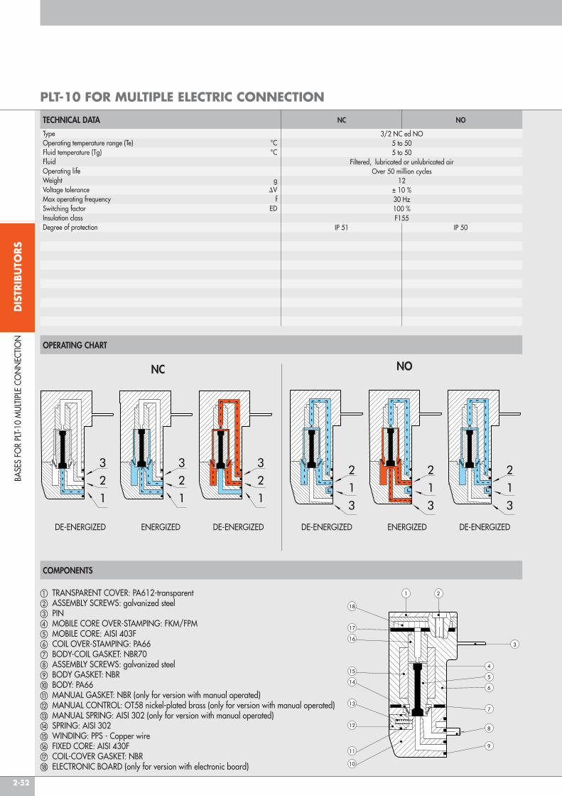
RS
PLT-10 solenoid valves are the latest development in modern pneumatic design, where the main trends focus on miniaturisation, enhanced performance, reduced power and reliability. Numerous versions are available, all with an ISO 15218 pneumatic interface. The power required to operate the PLT-10 has been greatly reduced, ranging from 0.3 to 0.8 Watts.It is available with a LED indicating when it is active. monostable manual control is also possible. None of the versions will get damaged if the polarity is accidentally inverted.
TECHNICAL DATA
COMPONENTS
TypeOperating temperature range (Te) °CFluid temperature (Tg) °CFluidOperating lifeWeight gVoltage tolerance DVmax operating frequency fSwitching factor EDInsulation classIndex of protectionPower connection
3/2 NC5 to 505 to 50
Filtered, lubricated or unlubricated air Over 50 million cycles
12± 10 %30 Hz100 %F155IP51
PLUG IN
a TrANSPArENT COVEr: PA612-transparentb ASSEmBLy SCrEWS: galvanized steelc COVEr: PA66d PINe mOBILE COrE OVEr-STAmPING: FKm/FPmf mOBILE COrE: AISI 403Fg COIL OVEr-STAmPING: PA66h BODy-COIL GASKET: NBr70i ASSEmBLy SCrEWS: galvanized steelj BODy GASKET: NBrk BODy: PA66l mANUAL GASKET: NBr (only for version with manual operated)m mANUAL CONTrOL: OT58 nickel-plated brass (only for version with manual operated)
n mANUAL SPrING: AISI 302 (only for version with manual operated)o SPrING: AISI 302p WINDING: PPS - Copper wireq FIXED COrE: AISI 430Fr COIL-COVEr GASKET: NBrs ELECTrONIC BOArD (only for version with electronic board)
10-m
m S
OLE
NO
ID V
ALV
ES S
ErIE
S PL
T-10
10-mm SOLENOID VALVES SERIES PLT-10
OPERATING CHART
DE-ENErGIZED ENErGIZED DE-ENErGIZED

2-48
DIS
TRIB
UTO
RS
PLT-10 WITH BASE AND CONNECTION ON THE SAME SIDE
PLT-10 WITH BASE AND CONNECTION ON OPPOSITE SIDES
10-m
m S
OLE
NO
ID V
ALV
ES S
ErIE
S PL
T-10
WITHOUT mANUAL
WITH mANUAL
WITHOUTmANUAL
WITHmANUAL
Version (3/2 NC) Code Manual Voltage Power Through Operating Flow rate at 6 Tmax coil a 24VDC Weight[Volt] [Watt] Ø [mm] press. [bar] ∆P=1 bar [Nl/min] Te 20°C a ED100% [°C] [g]
Without LED 722113330000 without 12 VDC 0.7 0.6 3 ÷ 7 9 93 12722113330100 with 12 VDC 0.7 0.6 3 ÷ 7 9 93 12722113340000 without 24 VDC 0.7 0.6 3 ÷ 7 9 93 12722113340100 with 24 VDC 0.7 0.6 3 ÷ 7 9 93 12
With LED 722113531000 without 12 VDC 0.8 0.6 3 ÷ 7 9 93 12722113531100 with 12 VDC 0.8 0.6 3 ÷ 7 9 93 12722113541000 without 24 VDC 0.8 0.6 3 ÷ 7 9 93 12722113541100 with 24 VDC 0.8 0.6 3 ÷ 7 9 93 12
SPEED-UP 722116841000 without 24 VDC 3/0.3 1.2 2 ÷ 7 16 51 12e LED 722116841100 with 24 VDC 3/0.3 1.2 2 ÷ 7 16 51 12
722116941000 without 24 VDC 4.2/0.7 1.2 2 ÷ 7 30 51 12722116941100 with 24 VDC 4.2/0.7 1.2 2 ÷ 7 30 51 12
Version (3/2 NC) Code Manuale Voltage Power Through Operating Flow rate at 6 Tmax coil a 24VDC Weight[Volt] [Watt] Ø [mm] press. [bar] ∆P=1 bar [Nl/min] Te 20°C a ED100% [°C] [g]
Without LED 722213330000 without 12 VDC 0.7 0.6 3 ÷ 7 9 93 12722213330100 with 12 VDC 0.7 0.6 3 ÷ 7 9 93 12722213340000 without 24 VDC 0.7 0.6 3 ÷ 7 9 93 12722213340100 with 24 VDC 0.7 0.6 3 ÷ 7 9 93 12
With LED 722213531000 without 12 VDC 0.8 0.6 3 ÷ 7 9 93 12722213531100 with 12 VDC 0.8 0.6 3 ÷ 7 9 93 12722213541000 without 24 VDC 0.8 0.6 3 ÷ 7 9 93 12722213541100 with 24 VDC 0.8 0.6 3 ÷ 7 9 93 12
SPEED-UP 722216841000 without 24 VDC 3/0.3 1.2 2 ÷ 7 16 51 12e LED 722216841100 with 24 VDC 3/0.3 1.2 2 ÷ 7 16 51 12
722216941000 without 24 VDC 4.2/0.7 1.2 2 ÷ 7 30 51 12722216941100 with 24 VDC 4.2/0.7 1.2 2 ÷ 7 30 51 12

2-49
DIS
TRIB
UTO
RS
KEY TO CODES
DIMENSIONS OF BASES FOR PLT-10
PLUG-IN CONNECTOR
10-m
m S
OLE
NO
ID V
ALV
ES S
ErIE
S PL
T-10
1 POSN. + POSN.
ACCESSORIES
Code Description0226009701 PLT-10 GASKET
N.B. 50 for pack
INTERFACE GASKET
Code DescriptionW0400100101 Base 1 posn. for PLT-10W0400100102 Base 2 posn. for PLT-10W0400100103 Base 3 posn. for PLT-10W0400100104 Base 4 posn. for PLT-10W0400100105 Base 5 posn. for PLT-10W0400100106 Base 6 posn. for PLT-10W0400100107 Base 7 posn. for PLT-10W0400100108 Base 8 posn. for PLT-10W0400100109 Base 9 posn. for PLT-10W0400100110 Base 10 posn. for PLT-10
Code DescriptionW0970512000 mACH 11 PLUG-IN
connector L = 300
Code Description0226009702 PLT-10 screw for aluminium
N.B. 100 for pack
Code Description Weight [g]W0400100200 Acc. cap 10 mm 6
Code Description0226009703 Screw PLT-10 for technopol.
N.B. 100 for pack
CAP FOR UNUSED POSITION STANDARD SECURING SCREW (FOR ALUMINIUM)
SECURING SCREWS FOR TECHNOPOLYMER
SPARE PARTS
When mounting on technopolymer bodies, use these screws instead of the ones supplied with the PLT-10.ATTENTION: approximative dimensions for not added glass plastic materials It’s always advisable to effect assembling tests.
7 2 2 1 1 3 3 4 0 1 00FAMILY POSITIONING POWER
CONNECTIONØ THROUGH POWER VOLTAGE LED MANUAL
CONTROLVERSION
Solenoid valvesseries “PLT-10”
1 Base and connection on same side2 Base and connection opposite sides
1 Plug-in 3 0.6 mm6 1.2 mm
3 0.7 W5 0.8 W8 3/0.3 W9 4.2/0.7 W
3 12 VDC4 24 VDC
0 -1 LED
0 -1 manual monostable
00 Standard

2-50
DIS
TRIB
UTO
RS
Series PLT-10 solenoid valves can be mounted on bases complete with electrical and pneumatic connections, from 4 to 24 positions. The electric contacts of each valve are linked to a single multiple connector via a printed circuit board. The connector has 9 pins or 25 pins, depending on the model and the number of valves that can be mounted. Versions with 25-pin connectors can interface with standard field buses by means of Profibus-DP, Can-Open and Device-Net modules for multimach. (see page 2-190).The compressed-air supply is common to all the valves and can be provided on either side of the base by means of a 1/8” fitting.Connection to the utilities is via automatic integrated cartridges for Ø 4 pipe. The solenoid valve outlet is free, in a slot in the base. The bases can be secured from above using m3 screws, or on a DIN bar using a bracket (see accessories).The bases can mount various types of PLT-10 solenoid valves: 3/2 NC, 3/2 NO, with or without a manual actuator.With this modular system, you can select the desired sequence of valves (NC, NO, blind) and change it at any time.
COMPONENTS
a Anodized aluminium baseb multi-pin electrical connectorc Automatic integrated cartridges for Ø 4 piped Electrical connectors for PLT-10 solenoid valves mounted on printed circuit boarde Securing screwf Technopolymer cover
25 PIN 9 PINPosition Nr° PLT Position Nr° PLTof electrical contact of electrical contact1 PLT1 1 PLT12 PLT2 2 PLT23 PLT3 3 PLT34 PLT4 4 PLT45 PLT5 5 PLT56 PLT6 6 PLT67 PLT7 7 PLT78 PLT8 8 PLT89 PLT9 9 COmmON (-)10 PLT1011 PLT1112 PLT1213 PLT1314 PLT1415 PLT1516 PLT1617 PLT1718 PLT1819 PLT1920 PLT2021 PLT2122 PLT2223 PLT2324 PLT2425 COmmON (-)
CONNECTION DIAGRAM
Pilot numbering from left to right, starting from the position closest to the connection.
BASE
S FO
r PL
T-10
mUL
TIPLE
CO
NN
ECTIO
N
BASES FOR PLT-10 MULTIPLE CONNECTION
TECHNICAL DATASupply voltagemax input W
Valve actuation indicatorOperating temperature range °CProtection degree (with valves and connectors mounted) maximum number of mountable PLT-10sNumber of contacts
12 VDC or 24 VDC0.7 per position for PLT-10 STD without LED
0.9 per position for PLT-10 STD with LED3/0.3 per position for PLT-10 NC with Speed-up3/0.7 per position for PLT-10 NO with Speed-up
4.2/0.7 per position for PLT-10 NC with Speed-up high flowLed mounted on the PLT-10 (on versions of solenoid valve where envisaged)
5 to 50IP 4024
9, of which 1 common, for versions with 4 and 8 positions25, of which 1 common, for versions with 4, 8, 12, 16, 20, 24 positions

2-51
DIS
TRIB
UTO
RS
ASSEMBLY OF SOLENOID VALVES AND ACCESSORIES
CODES AND DIMENSIONS FOR BASES 9 AND 25 PINS
HOW TO SECURE THE BASE
A From above using m3 screwsB On a DIN bar, using the bracket and screws provided The bases come with the rear holes plugged by provided dowels.
Code Description N° of PINS N° of positions L1 L2 L3 L4 L5 Weight [g]0210040004 4-posn. base PLT 10 9-PIN mult conn. 9 4 81.9 10.6 18 41 19.6 1600210040008 8-posn. base PLT 10 9-PIN mult conn. 9 8 122.5 10.6 18 41 19.6 235
0210240004 4-posn. base PLT 10 25-PIN mult conn. 25 4 104.8 15.5 30 63.9 30.5 2100210240008 8-posn. base PLT 10 25-PIN mult conn. 25 8 145.4 15.5 30 63.9 30.5 2800210240012 12-posn. base PLT 10 25-PIN mult conn. 25 12 186 15.5 30 63.9 30.5 3550210240016 16-posn. base PLT 10 25-PIN mult conn. 25 16 226.6 15.5 30 63.9 30.5 4300210240020 20-posn. base PLT 10 25-PIN mult conn. 25 20 267.2 15.5 30 63.9 30.5 5000210240024 24-posn. base PLT 10 25-PIN mult conn. 25 24 307.8 15.5 30 63.9 30.5 575
A B
BASE
S FO
r PL
T-10
mUL
TIPLE
CO
NN
ECTIO
N
a Solenoid valveb Pneumatic circuit cap for blind positionc Electric circuit cap for blind position (use two identification labels)d Identification labele Electrical connector
2-52
DIS
TRIB
UTO
RS
OPERATING CHART
COMPONENTS
BASE
S FO
r PL
T-10
mUL
TIPLE
CO
NN
ECTIO
N
PLT-10 FOR MULTIPLE ELECTRIC CONNECTION
TECHNICAL DATATypeOperating temperature range (Te) °CFluid temperature (Tg) °CFluidOperating lifeWeight gVoltage tolerance DVmax operating frequency fSwitching factor EDInsulation classDegree of protection
NC NO
3/2 NC ed NO5 to 505 to 50
Filtered, lubricated or unlubricated air Over 50 million cycles
12± 10 %30 Hz100 %F155
IP 51 IP 50
a TrANSPArENT COVEr: PA612-transparentb ASSEmBLy SCrEWS: galvanized steelc PINd mOBILE COrE OVEr-STAmPING: FKm/FPme mOBILE COrE: AISI 403Ff COIL OVEr-STAmPING: PA66g BODy-COIL GASKET: NBr70h ASSEmBLy SCrEWS: galvanized steeli BODy GASKET: NBrj BODy: PA66k mANUAL GASKET: NBr (only for version with manual operated)l mANUAL CONTrOL: OT58 nickel-plated brass (only for version with manual operated)m mANUAL SPrING: AISI 302 (only for version with manual operated)n SPrING: AISI 302o WINDING: PPS - Copper wirep FIXED COrE: AISI 430Fq COIL-COVEr GASKET: NBrr ELECTrONIC BOArD (only for version with electronic board)
DE-ENErGIZED ENErGIZED DE-ENErGIZED DE-ENErGIZED ENErGIZED DE-ENErGIZED
NC NO

2-53
DIS
TRIB
UTO
RS
PLT-10 NC-NO FOR MULTIPLE ELECTRIC CONNECTION
BASE
S FO
R PL
T-10
MUL
TIPLE
CO
NN
ECTIO
N
WIThOUTMANUAL
WIThMANUAL
Version (3/2 NC) Code Manual Voltage Power Ø Through Operating Flow rate at 6 T Max coil T at 24VDC Weight[Volt] [Watt] [mm] pressure [bar] ∆P=1 bar [Nl/min] Te 20°C a ED100% [°C] [g]
Without LED 722123330000 without 12 VDC 0.7 0.6 3 to 7 9 93 12722123330100 with 12 VDC 0.7 0.6 3 to 7 9 93 12722123340000 without 24 VDC 0.7 0.6 3 to 7 9 93 12722123340100 with 24 VDC 0.7 0.6 3 to 7 9 93 12
With LED 722123531000 without 12 VDC 0.8 0.6 3 to 7 9 93 12722123531100 with 12 VDC 0.8 0.6 3 to 7 9 93 12722123541000 without 24 VDC 0.8 0.6 3 to 7 9 93 12722123541100 with 24 VDC 0.8 0.6 3 to 7 9 93 12
SPEED-UP 722126841000 without 24 VDC 3/0.3 1.2 2 to 7 16 51 12and LED 722126841100 with 24 VDC 3/0.3 1.2 2 to 7 16 51 12
722126941000 without 24 VDC 4.2/0.7 1.2 2 to 7 30 51 12722126941100 with 24 VDC 4.2/0.7 1.2 2 to 7 30 51 12
Version (3/2 NO) Code Manual Voltage Power Ø Through Operating Flow rate at 6 T Max coil T at 24VDC Weight[Volt] [Watt] [mm] pressure [bar] ∆P=1 bar [Nl/min] Te 20°C a ED100% [°C] [g]
SPEED-UP 722126841010 without 24 VDC 3/0.7 1.0 2 to 7 14 51 12and LED 722126841110 with 24 VDC 3/0.7 1.0 2 to 7 14 51 12
KEY TO CODES
7 2 2 1 2 3 3 4 0 1 0 0
FAMILY POSITIONINGPOWER Ø
POWER VOLTAGE LEDMANUAL
VERSIONCONNECTION ThROUGh CONTROL
Solenoid valvesseries “PLT-10”
1 Base and connection on same side
2 for multiple base
3 0.6 mm6 1.2 mm
3 0.7 W5 0.8 W8 3/0.3 W for NC 3/0.7 W for NO9 4.2/0.7 W
3 12 VDC4 24 VDC
0 -1 LED
0 -1 manual monostable
0 NC1 NO
0 Standard

2-54
DIS
TRIB
UTO
RS
CONNECTION BRACKETS ON BAR OMEGA (DIN EN 50022)
CAP FOR UNUSED POSITION
STRAIGHT AND 90° CONNECTOR KIT, 9 WIRES
STRAIGHT AND 90° CONNECTOR KIT, 25 WIRES
CABLES
ACCESSORIES
Code Description Weight [g]0227301610 Connection brackets on din BAr for bases PLT-10 30
Supplied complete with one m3x20 screws and one m6 grub screwIndividually packed
Code Description Weight [g]W0400100200 Cap 10 mm 6
Code Description Weight [g]0226180102 Straight and 90° connector kit, 9 wires 31
Code Description Weight [g]0226180101 Straight and 90° connector kit, 25 wires 48
Code Description Weight [g]0226107201 10-wire cable 860226107101 19-wire cable 1220226107102 25-wire cable 130
Specify the number of metres desired
ACC
ESSO
rIES
FO
r BA
SES
FOr
PLT-
10 m
ULTIP
LE C
ON
NEC
TION

2-55
DIS
TRIB
UTO
RS
STRAIGHT PRE-WIRED CONNECTOR KIT
PRE-WIRED 90° CONNECTOR
WIRING DIAGRAM FOR PRE-WIRED PLUG CONNECTORS
IDENTIFICATION PLATE KIT
R17 - PIPE RELEASE SPANNER
Code Description Weight [g]0226900100 Connector + 9-wire axial cable L = 1 m 900226900250 Connector + 9-wire axial cable L = 2.5 m 2200226900500 Connector + 9-wire axial cable L = 5 m 434
0226920100 Connector + 25-wire axial cable L = 1 m 1320226920250 Connector + 25-wire axial cable L = 2.5 m 3200226920500 Connector + 25-wire axial cable L = 5 m 636
Code Description Weight [g]0226910100 Connector + 9-wire 90° cable L = 1 m 900226910250 Connector + 9-wire 90° cable L = 2.5 m 2200226910500 Connector + 9-wire 90° cable L = 5 m 434
0226930100 Connector + 25-wire 90° cable L = 1 m 1320226930250 Connector + 25-wire 90° cable L = 2.5 m 3200226930500 Connector + 25-wire 90° cable L = 5 m 636
Code Description Ø Tube2L17001 rL17 from Ø 3 to Ø 10
Code Description Weight [g]0226107000 Identification plate kit 30
Comes in 10-pc. packs
ACC
ESSO
rIES
FO
r BA
SES
FOr
PLT-
10 m
ULTIP
LE C
ON
NEC
TION
25 PIN 9 PINPosition of Colour of the Position of Colour of the Position of Colour of the Position of Colour of theelectrical contact corresponding wire electrical contact corresponding wire electrical contact corresponding wire electrical contact corresponding wire1 blue/black 10 brown/white 19 yellow/black 1 green/black2 red/brown 11 red/orange 20 white 2 white3 white/black 12 light blue 21 blue/white 3 blue/black4 red/blue 13 yellow/white 22 brown 4 blue5 black/orange 14 yellow 23 green/white 5 yellow/black6 yellow/red 15 red/green 24 red 6 yellow7 black/brown 16 orange 25 green/black 7 red/black8 white/red 17 orange/white 8 green9 red/black 18 green 9 white/black
Lenght = 140 mm