Embed Size (px)
Citation preview

10 - Network Layer

Network layer transport segment from sending to receiving
host on sending side encapsulates segments into
datagrams on rcving side, delivers segments to transport
layer network layer protocols in every host, router Router examines header fields in all IP
datagrams passing through it
networkdata linkphysical
networkdata linkphysical
networkdata linkphysical
networkdata linkphysical
networkdata linkphysical
networkdata linkphysical
networkdata linkphysical
networkdata linkphysical
application
transportnetworkdata linkphysical
application
transportnetworkdata linkphysical
Key Network-Layer Functions
forwarding: move packets from router’s input to appropriate router output
routing: determine route taken by packets from source to dest.
Routing algorithms
analogy:
routing: process of planning trip from source to dest
forwarding: process of getting through single interchange

1
23
0111
value in arrivingpacket’s header
routing algorithm
local forwarding tableheader value output link
0100010101111001
3221
Interplay between routing and forwarding

Connection setup
3rd important function in some network architectures: ATM, frame relay, X.25
Before datagrams flow, two hosts and intervening routers establish virtual connection Routers get involved
Network and transport layer cnctn service: Network: between two hosts Transport: between two processes
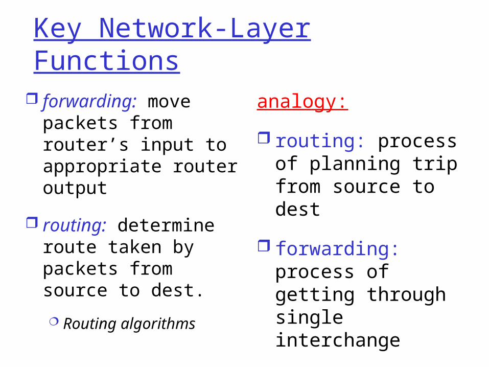
Network service model
Q: What service model for “channel” transporting datagrams from sender to receiver?
Example services for individual datagrams:
guaranteed delivery Guaranteed delivery
with less than 40 msec delay i.e. bounded delay
Example services for a flow of datagrams:
In-order datagram delivery
Guaranteed minimum bandwidth to flow
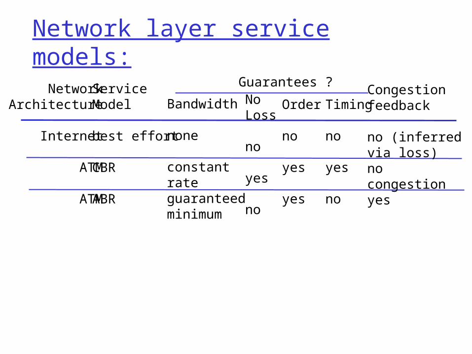
Network layer service models:
NetworkArchitecture
Internet
ATM
ATM
ServiceModel
best effort
CBR
ABR
Bandwidth
none
constantrateguaranteed minimum
NoLoss
no
yes
no
Order
no
yes
yes
Timing
no
yes
no
Congestionfeedback
no (inferredvia loss)nocongestionyes
Guarantees ?

Network Layer 4-8
Network layer connection and connection-less service
Datagram network provides network-layer connectionless service
VC network provides network-layer connection service
Analogous to the transport-layer services, but: Service: host-to-host No choice: network provides one or the
other Implementation: in the core

Network Layer 4-9
Virtual circuits
call setup, teardown for each call before data can flow each packet carries VC identifier (not destination host
address) every router on source-dest path maintains “state” for
each passing connection link, router resources (bandwidth, buffers) may be
allocated to VC
“source-to-dest path behaves much like telephone circuit” performance-wise network actions along source-to-dest path

Network Layer 4-10
VC implementation
A VC consists of:1. Path from source to destination2. VC numbers, one number for each link along
path3. Entries in forwarding tables in routers along
path Packet belonging to VC carries a VC
number. VC number must be changed on each
link. New VC number comes from forwarding table

Network Layer 4-11
Forwarding table
12 22 32
1 32
VC number
interfacenumber
Incoming interface Incoming VC # Outgoing interface Outgoing VC #
1 12 2 222 63 1 18 3 7 2 171 97 3 87
… … … …
Forwarding table innorthwest router:
Routers maintain connection state information!
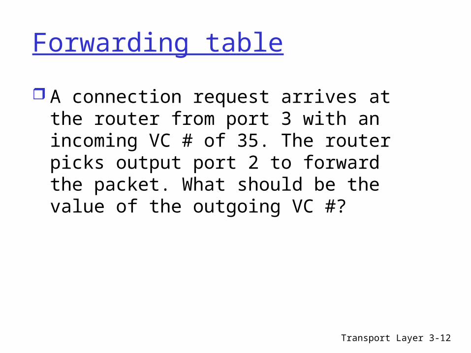
Forwarding table
A connection request arrives at the router from port 3 with an incoming VC # of 35. The router picks output port 2 to forward the packet. What should be the value of the outgoing VC #?
Transport Layer 3-12

Network Layer 4-13
Virtual circuits: signaling protocols
used to setup, maintain teardown VC used in ATM, frame-relay, X.25 not used in today’s Internet
application
transportnetworkdata linkphysical
application
transportnetworkdata linkphysical
1. Initiate call 2. incoming call
3. Accept call4. Call connected
5. Data flow begins 6. Receive data

Network Layer 4-14
Datagram networks no call setup at network layer routers: no state about end-to-end connections
no network-level concept of “connection”
packets forwarded using destination host address packets between same source-dest pair may take
different paths
application
transportnetworkdata linkphysical
application
transportnetworkdata linkphysical
1. Send data 2. Receive data

Network Layer 4-15
Forwarding table
Destination Address Range Link Interface
11001000 00010111 00010000 00000000 through 0 11001000 00010111 00010111 11111111
11001000 00010111 00011000 00000000 through 1 11001000 00010111 00011000 11111111
11001000 00010111 00011001 00000000 through 2 11001000 00010111 00011111 11111111
otherwise 3
4 billion possible entries

Network Layer 4-16
Longest prefix matching
Prefix Match Link Interface 11001000 00010111 00010 0 11001000 00010111 00011 1 11001000 00010111 00011000 2 otherwise 3
DA: 11001000 00010111 00011000 10101010
Examples
DA: 11001000 00010111 00010110 10100001 Which interface?
Which interface?

Network Layer 4-17
Datagram or VC network: why?
Internet data exchange among
computers “elastic” service, no
strict timing req. “smart” end systems
(computers) can adapt, perform
control, error recovery simple inside network,
complexity at “edge” many link types
different characteristics uniform service difficult
ATM evolved from telephony human conversation:
strict timing, reliability requirements
need for guaranteed service
“dumb” end systems telephones complexity inside
network

Network Layer 4-18
Chapter 4: Network Layer
4. 1 Introduction 4.2 Virtual circuit and datagram networks 4.3 What’s inside a router 4.4 IP: Internet Protocol
Network Layer 4-19
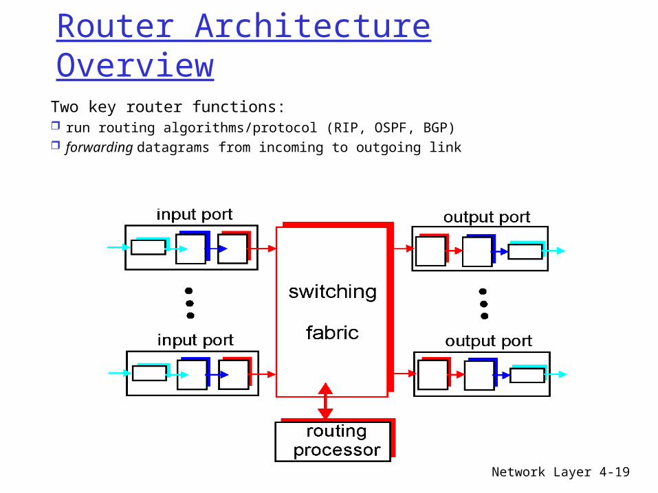
Router Architecture Overview
Two key router functions: run routing algorithms/protocol (RIP, OSPF, BGP) forwarding datagrams from incoming to outgoing link

Network Layer 4-20
Input Port Functions
Decentralized switching: given datagram dest., lookup output
port using forwarding table in input port memory
goal: complete input port processing at ‘line speed’
queuing: if datagrams arrive faster than forwarding rate into switch fabric
Physical layer:bit-level reception
Data link layer:e.g., Ethernetsee chapter 5
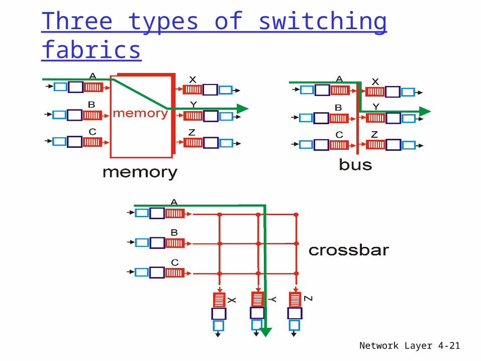
Network Layer 4-21
Three types of switching fabrics

Network Layer 4-22
Switching Via MemoryFirst generation routers: traditional computers with switching under direct control of CPUpacket copied to system’s memory speed limited by memory bandwidth (2 bus crossings per datagram)
InputPort
OutputPort
Memory
System Bus
Network Layer 4-23
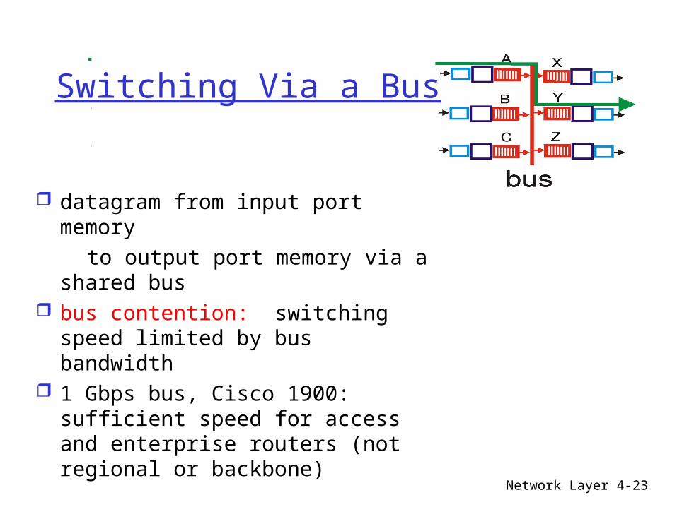
Switching Via a Bus
datagram from input port memory
to output port memory via a shared bus
bus contention: switching speed limited by bus bandwidth
1 Gbps bus, Cisco 1900: sufficient speed for access and enterprise routers (not regional or backbone)
Network Layer 4-24
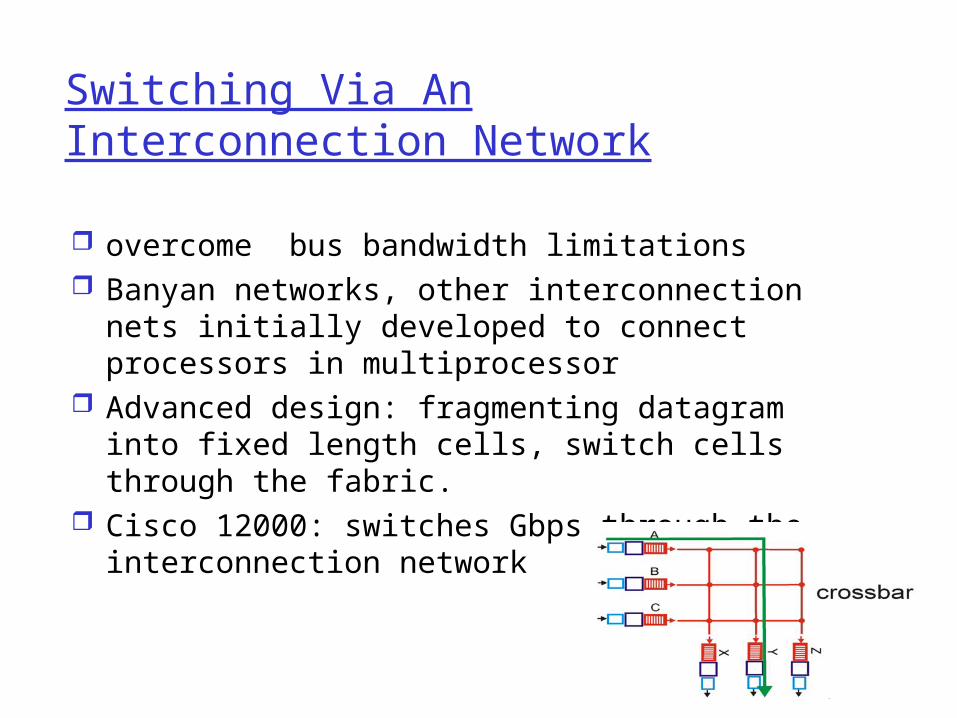
Switching Via An Interconnection Network
overcome bus bandwidth limitations Banyan networks, other interconnection nets
initially developed to connect processors in multiprocessor
Advanced design: fragmenting datagram into fixed length cells, switch cells through the fabric.
Cisco 12000: switches Gbps through the interconnection network

Network Layer 4-25
Output Ports
Buffering required when datagrams arrive from fabric faster than the transmission rate
Scheduling discipline chooses among queued datagrams for transmission

Network Layer 4-26
Output port queueing
buffering when arrival rate via switch exceeds output line speed
queueing (delay) and loss due to output port buffer overflow!

Network Layer 4-27
Input Port Queuing
Fabric slower than input ports combined -> queueing may occur at input queues
Head-of-the-Line (HOL) blocking: queued datagram at front of queue prevents others in queue from moving forward
queueing delay and loss due to input buffer overflow!