Embed Size (px)
Citation preview
8/10/2019 10-Overview of CDMA 2000 1x EVDO
http://slidepdf.com/reader/full/10-overview-of-cdma-2000-1x-evdo 1/13
E1-E2 UPGRADATION COURSE –CONSUMER
MOBILITY
Overview of CDMA 2000 1X & EVDO
8/10/2019 10-Overview of CDMA 2000 1x EVDO
http://slidepdf.com/reader/full/10-overview-of-cdma-2000-1x-evdo 2/13
E1-E2 Consumer Mobility Rev date:17-03-11
Page No:2For Internal Circulation Only
CHAPTER-IX
CDMA Network Architecture
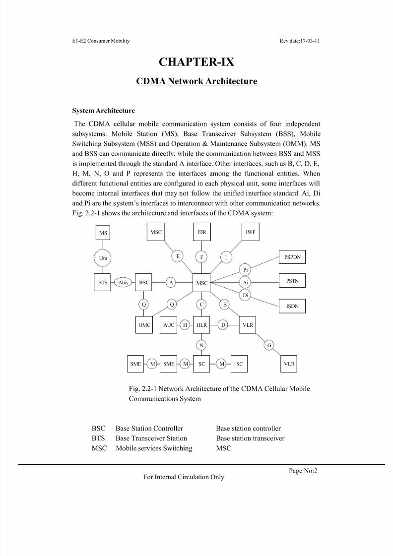
System Architecture
The CDMA cellular mobile communication system consists of four independentsubsystems: Mobile Station (MS), Base Transceiver Subsystem (BSS), MobileSwitching Subsystem (MSS) and Operation & Maintenance Subsystem (OMM). MSand BSS can communicate directly, while the communication between BSS and MSSis implemented through the standard A interface. Other interfaces, such as B, C, D, E,H, M, N, O and P represents the interfaces among the functional entities. Whendifferent functional entities are configured in each physical unit, some interfaces will
become internal interfaces that may not follow the unified interface standard. Ai, Diand Pi are the system’s interfaces to interconnect with other communication networks.Fig. 2.2-1 shows the architecture and interfaces of the CDMA system:
MSCA AiBSCBTS Abis
MS
OMC HLR
C
Um
AUC H
Q Q
D VLR
B
VLR
G
SC
N
SCSMESME M M M
PSTN
PSPDN
ISDN
Pi
Di
EIR IWFMSC
F LE
Fig. 2.2-1 Network Architecture of the CDMA Cellular MobileCommunications System
BSC Base Station Controller Base station controllerBTS Base Transceiver Station Base station transceiverMSC Mobile services Switching MSC
8/10/2019 10-Overview of CDMA 2000 1x EVDO
http://slidepdf.com/reader/full/10-overview-of-cdma-2000-1x-evdo 3/13
E1-E2 Consumer Mobility Rev date:17-03-11
Page No:3For Internal Circulation Only
Center
OMCOperation and Maintenance
Center
Operations & maintenance
center
AUC Authentication Center Authentication Center
EIREquipment Identification
Register
Equipment Identification
Register
HLR Home Location Register HLR
VLR: Visitor Location Register VLR
MS Mobile Station Mobile station
ISDNIntegrated Services Digital
Network
Integrated service digital
network
PST
N
Public Switched Telephone
Network
Public Switching Telephone
Network
PSPD
N
Public Switched Public Data
Network
Public Switched Public Data
Network
PLM
NPublic Land Mobile Network Public land mobile network
SC Short Message Center Short message center
An Introduction to Network Entities
BTS Subsystem
The BTS Subsystem (BSS) is the assembly of radio equipment and radio channelcontrol equipment, serving one or more cellular cells. In certain radio coverage, it iscontrolled by the Mobile Switching Center (MSC) to implement channel assignment,user access and paging, and information transfer. Normally, the BSS consists of one ormore BSCs and BTSs. The BTS is responsible for radio transmission and BSC forcontrol and management.
Base Transceiver
The Base Transceiver (BTS) belongs to the radio part of a basestation system.Controlled by BSC, it serves the radio transceiving equipment of a certain cell,implements the conversion between BSC and radio channels, radio transmissionthrough air interface between BTS and MS and related control, and communicateswith BSC through the Abis interface.
8/10/2019 10-Overview of CDMA 2000 1x EVDO
http://slidepdf.com/reader/full/10-overview-of-cdma-2000-1x-evdo 4/13
E1-E2 Consumer Mobility Rev date:17-03-11
Page No:4For Internal Circulation Only
Base Station Controller
One end of the Base Station Controller (BSC) can be connected with one or moreBTSs, while its other end can be connected with MSC and OMC. Oriented to radionetwork, BSC implements radio network management, radio resource management
and radio BTS monitoring and management. It also controls the establishment,connection and disconnection of radio connection between MS and BTS, controls the positioning, handoff and paging of MS, provides voice coding and rate adjustmentand carries out operation and maintenance of the BSS.
Mobile Switching Subsystem
The Mobile Switching Subsystem (MSS) implements the main switching functions ofthe CDMA network. Meanwhile it manages the database for user data and mobility.
Mobile Switching CenterMSC is the core of the CDMA network. It controls and implements voice channelconnection for MSs within its coverage, namely serving as an interface betweenCDMA and other networks. The functions MSC carries out include call connection,charging, BSS-MSC handoff, assist radio resource management and mobilitymanagement. Besides, each MSC also implements the GMSC function for call routeestablishment to the MS, namely, to query the location information of each MS. MSCgets all data required for call request processing from three databases, VLR, HLR andAUC.
Visitor Location Register
The Visitor Location Register (VLR) is a dynamic user database, storing the relateduser data of all MSs (visitors) within the MSC’s management range, including userID, MS’s location area information, user status and services available for the user.VLR gets and stores all necessary data from the HLR of a mobile subscriber. Once themobile subscriber leaves the control area of the VLR, it will be registered in anotherVLR, and the previous VLR will delete its data log.
Home Location Register
The Home Location Register (HLR) is a static database, storing the data for mobilesubscriber management. Each mobile subscriber should be registered in its HLR. Itstores two kinds of information: parameters related with the mobile subscriber,including the subscriber’s ID, access capability, user type and supplementary service;current location information of the subscriber for call route establishment. Forexample: the address of MSC or VLR. No matter where the mobile subscriber roams,
8/10/2019 10-Overview of CDMA 2000 1x EVDO
http://slidepdf.com/reader/full/10-overview-of-cdma-2000-1x-evdo 5/13
E1-E2 Consumer Mobility Rev date:17-03-11
Page No:5For Internal Circulation Only
its HLR should provide all related parameters and input the latest location into thedatabase.
Authentication Center
The Authentication Center (AUC), a functional entity managing the authenticationinformation related with mobile stations (MSs). It implements MS authentication,stores the MS authentication parameters, generates and sends the correspondingauthentication parameters according to the requests of MSC or VLR, including A-KEY, SSD, ESN, MIN and AAV, and then calculates all random numbers to get theauthentication result.
Short Message Center
The Short Message Center (SC) is responsible for receiving, storing and forwardingshort messages between the CDMA mobile subscribers and fixed line users or
between mobile subscribers. It serves as a postal office, receiving mails from every place, sorts them out and then distribute them to the corresponding users. ThroughSC, the messages can be sent to destination more reliably.The short message servicesinclude point-to-point server and cell broadcast service.
Operation and Maintenance Management Subsystem (OMM)
The Operation & Maintenance Center (OMC) provides equipment operators withnetwork operation and maintenance services, manages subscriber information, makesnetwork planning and improves the efficiency and service quality of the whole
system. OMC includes OMC-S and OMC-R, depending on the part for maintenance.OMC-S is responsible for the maintenance on the MSS side while OMC-R isresponsible for the maintenance on the BSS side. Its specific functions include:maintenance test, obstacle check and handling, system status monitoring, realtimesystem control, office data modification, performance management, subscribertracking, alarm and traffic measurement.
Interfaces and Protocols
According to the Open System Interconnection (OSI) model, we can analyze theCDMA network on the aspects of interface, protocol and interface functions in detail.
Interfaces
As shown in Fig. 2.2-1, various interfaces exist in the CDMA system. They candivided into the following categories according to different subsystems: Air interface
8/10/2019 10-Overview of CDMA 2000 1x EVDO
http://slidepdf.com/reader/full/10-overview-of-cdma-2000-1x-evdo 6/13
E1-E2 Consumer Mobility Rev date:17-03-11
Page No:6For Internal Circulation Only
Um between mobile terminals and the BSS, A interface between BSS and MSS, andother interfaces between internal entities of the network.
Air interface
The Um interface is defined as the communication interface between MS and BTS. Itis the key distinguishing the CDMA network from the GSM network and the mostimportant interface of the CDMA network.This interface grants compatibility to MSs from different suppliers and networks ofdifferent operators, enables MSs to roam, ensures the frequency efficiency of thecellular system, and adopts a series of anti-interference technologies and interference
preventing measures. Obviously, the Um interface implements the physicalconnection from MS to the fixed part of the CDMA system, i.e. the wirelessconnection. Besides, it transfers information for radio resource management, mobilitymanagement and connection management.
Interface between BSS and MSS – A interface
The A interface is located between MSC and BSC. Its physical link is implementedthrough standard PCM digital transmission link of 2.048Mbit/s. It transfersinformation for MS management, BTS management, mobility management andconnection management.
BSS internal interface (Abis)
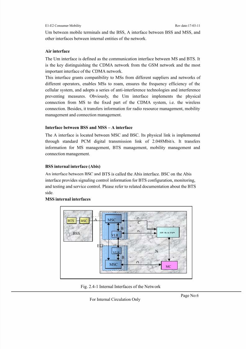
An interface between BSC and BTS is called the Abis interface. BSC on the Abisinterface provides signaling control information for BTS configuration, monitoring,and testing and service control. Please refer to related documentation about the BTSside.MSS internal interfaces
Fig. 2.4-1 Internal Interfaces of the Network
MSC
B
B
BSS
CBSC
VLR
VLR
MSC MC
E N
BTS A
8/10/2019 10-Overview of CDMA 2000 1x EVDO
http://slidepdf.com/reader/full/10-overview-of-cdma-2000-1x-evdo 7/13
E1-E2 Consumer Mobility Rev date:17-03-11
Page No:7For Internal Circulation Only
In Fig. 2.4-1, the MSS part contains the names of interfaces between equipmententities. They will be described one by one in the coming part.
B interface
As an internal interface between VLR and MSC, the B interface is used by the MSCto request the current location information of the MS from VLR or notify the VLR toupdate the location information of the MS.
C interface
As an interface between HLR and MSC, the C interface transfers information forroute selection and management. Once a call is required to a MS, the Gateway MSC(GMSC) will request the roaming number of the called MS from the HLR of thecalled side. The physical link of the C interface is 2.048Mbit/s standard PCM digitaltransmission cable.
D interface
As an interface between HLR and VLR, the D interface exchanges informationrelated with MS location and user management. It ensures that the MS can establishand receives calls within the entire service area. Its physical link is 2.048Mbit/sstandard digital link.
E interface
It is the interface controlling different MSCs of adjacent areas. When the MS moves,
during a call, from the control area of one MSC to that of another MSC, this interfacecan be used to exchange related handoff information to activate and complete handoff,and thus to complete the cross-cell channel handoff process without interrupting thecommunication. Its physical link is implemented through 2.048Mbit/s standard digitallink between MSCs.
N interface
This interface is used to transfer route information related with the called subscriber between MC and HLR. Its physical link is implemented through 2.048Mbit/s standarddigital link.
Q interface
It is an interface between MS and MSC transferring short messages.match the OSIreference model. The purpose of this structure is to allow the isolation of differentsignaling protocols, describing protocols according to continuous independenthierarchy. Each layer of protocol provides specified service at the agreed serviceaccess point for its upper layer protocol.
8/10/2019 10-Overview of CDMA 2000 1x EVDO
http://slidepdf.com/reader/full/10-overview-of-cdma-2000-1x-evdo 8/13
E1-E2 Consumer Mobility Rev date:17-03-11
Page No:8For Internal Circulation Only
CDMA 2000 1x air interface:-
Forward channels:
Forward links (from base station to mobile station) provide the communication from base station to mobile station.
Channel Types and FunctionsThe forward links comprise the following logic channels:
• Forward pilot channel (F_PICH)
It functions the same as the IS-95A forward pilot channel. The base station usesthis channel to transmit the pilot signals that identify it and guide the mobilestations to access the network.
• Forward sync channel (F-SYNCH)
It functions the same as IS-95A forward sync channel. The base station sends thesystem time and frame synchronization information to the mobile stations via thischannel to keep timing and synchronize with the system.
• Forward paging channel (F-PCH)
It functions the same as IS-95 forward paging channel. The base station transmits paging, command, and traffic channel allocation information to the mobilestations via this channel.
• Forward quick paging channel (F-QPCH)
It is used by the base station to quickly instruct the mobile station from whichtime slot to receive the control message on F-PCH or F-CCCH. The mobile station
does not need to monitor F-PCH or F-CCCH time slot all the time, so it savesmuch battery.
• Forward broadcast control channel (F-BCCH)
It is used by the base station to deliver system messages to the mobile station.• Common assignment channel (F-CACH)
The F-CACH is always used together with the F-CPCCH, R-EACH and R-CCCH.When the base station demodulates an R-EACH header, it instructs the mobilestation, via F-CACH, which R-CCCH to use to send the access message, and fromwhich F-CPCH sub channel to receive the power control bit.
• Forward common power control channel (F-CPCCH)
When the mobile station sends data in R-CCCH, the base station transmits reverse power control bit to the mobile station via this channel.
• Forward common control channel (F-CCCH)
8/10/2019 10-Overview of CDMA 2000 1x EVDO
http://slidepdf.com/reader/full/10-overview-of-cdma-2000-1x-evdo 9/13
E1-E2 Consumer Mobility Rev date:17-03-11
Page No:9For Internal Circulation Only
It is used by the base station and the mobile station to exchange control messagesand short impulsive data when the mobile station has not set up a traffic channelyet.
• Forward dedicated control channel (F-DCCH)
When the mobile station is in traffic channel state, it is used by the base station totransmit messages or low-rate packet and circuit data services to the mobilestation..
• Forward fundamental traffic channel (F-FCH)
This channel is used to carry signaling, voice, low-rate packet service, circuit dataservices or auxiliary service when the mobile station enters traffic channel state.
• Forward supplemental channel (F-SCH)
This channel is used to carry high-rate packet data service on the forward linkwhen the mobile station enters traffic channel state.
• Forward supplemental code channel (F-SCCH)
This channel is used for data transfer.
• Forward power control sub-channel (F-PCSCH)
This channel transmits persistently on the forward traffic channel. It is used forreverse power control.
Reverse links (from mobile station to base station) provide the communication frommobile station to base station.
Reverse Channels:The reverse channels include:
• Reverse pilot channel (R_PICH)
It is used to assist the base station to detect the data transmitted by mobilestations.
• Reverse access channel (R-ACH)
Its functions are the same as the IS-95A reverse access channel.• Reverse common control channel (R-CCCH)
It is used by the base station and the mobile station to exchange control messages
and short impulsive data when the mobile station has not set up a traffic channelyet.
• Reverse enhanced access channel (R-EACH)
The mobile station sends control messages on this channel to the base stationwhen it has not yet set up a traffic channel, thus improving mobile stationaccessibility.
8/10/2019 10-Overview of CDMA 2000 1x EVDO
http://slidepdf.com/reader/full/10-overview-of-cdma-2000-1x-evdo 10/13
E1-E2 Consumer Mobility Rev date:17-03-11
Page No:10For Internal Circulation Only
• Reverse dedicated control channel (R-DCCH)
When the mobile station is in traffic channel state, it uses this channel to transmitmessages or low-rate packet and circuit data services to the base stations.
• Reverse fundamental channel (R-FCH)
It is used to carry signaling, voice, low-rate packet and circuit data services, orauxiliary services on the reverse link when the mobile station enters trafficchannel state.
• Reverse supplemental channel (R-SCH)
It is used to carry high-rate packet data service on the reverse link when themobile station enters traffic channel state.
• Reverse supplemental code channel (R-SCCH)
It is used to send user information to the base station during a call.
• Reverse power control sub-channel (R-PCSCH)This channel is the sub-channel of reverse pilot channel. It includes reverse main
power control sub-channel and reverse auxiliary power control sub-channel. Thechannel is used for forward power control.
CDMA2000 1x EV-DO
.
System Overview
EV-DO in CDMA2000 1x EV-DO is an acronym for Evolution Data Optimized orEvolution Data Only. High-speed data transmission necessitated the evolution fromCDMA2000 1x to CDMA2000 1x EV-DO Qualcomm and Lucent jointly developedthe 1x EV-DO specification IS-856.1x EV-DO system structure involves a new radionetwork part overlaying the 1x system. 1x system provides voice services andlow/medium-speed data services. 1x EV-DO system provides high-speed packet dataservices1x EV-DO and 1x systems use different carriers to transfer data. Optimizingvoice and high-speed packet data services helps achieve optimum performance. At the
same narrowband CDMA frequency bandwidth, 1x EV-DO provides the highest datatransmission up to 3.1 Mb/s. Since 1x EV-DO evolved from 1x systems, it inherits the1x system radio features. It is equivalent to the new frequencies of 1x system. 1x EV-DO system RF equipment is compatible with 1x system.
Network Model
1x EV-DO network model has two developing routines; interoperability specification
8/10/2019 10-Overview of CDMA 2000 1x EVDO
http://slidepdf.com/reader/full/10-overview-of-cdma-2000-1x-evdo 11/13
E1-E2 Consumer Mobility Rev date:17-03-11
Page No:11For Internal Circulation Only
for High Rate Packet Data Access (HRPDA) Network Interface Revision 0 andRevision A. Difference between the two models is the presence or absence of SC/MM(Spread Carrier/Mobility Management) function in PCF.
System Features .
Forward ChannelsForward links from AN to AT provide communication between ATs in the AN.Forward links have the following features:
• Data rates range from 38.4 Kb/s ~ 3.1 Mb/s.
• Forward channels transmit full power without any power control.
• According to the forward channel C/I measurement, AT selects the best servicesector and applies for the highest data rate that the current forward channel cansupport.
• All users belonging to the same service sector share unique data servicechannel in the TDMA mode.
As an independent system, 1x EV-DO system follows a completely new channelstructure.
.
Reverse Channels
Forward links (from AT to AN) provide the communication between ATs and the AN.Following are the Reverse channel features:
• Data rate can reach at most 307.2 Kb/s.
• Reverse channels follow soft handoff.
• Reverse channels follow Dynamic power control.
• Use of Rate control enables reverse link load adjustment.
Key 1x EV-DO Technologies .
Reverse Link Power Control
Power control maximizes system capacity. In 1x EV-DO system, there is no forwardlink power control because forward link power is constant. Reverse link follows
power control. Reverse link power control aims to control output power of ATs while
minimizing interference, maintaining high reverse data link quality. When reverse linksignal-to-noise ratio (SNR) per user is lowest for acceptable performance, capacity ishighest.
Reverse Link Rate Control
In 1x EV-DO standard, AT can adjust reverse rate ranging from 9.6 Kb/s to 307.2Kb/s. The system must control the load on reverse links to avoid too many users in the
8/10/2019 10-Overview of CDMA 2000 1x EVDO
http://slidepdf.com/reader/full/10-overview-of-cdma-2000-1x-evdo 12/13
E1-E2 Consumer Mobility Rev date:17-03-11
Page No:12For Internal Circulation Only
same sector transmitting data to AN at a high rate. This leads to all ATs becomingunavailable. AN follows the two mechanisms described to control the AT transmitrate: Reverse rate limit (RRL): AN restricts the maximum reverse rate of ATto alevel below 307.2 Kb/s using Broadcast Reverse Rate Limit or Unicast Reverse RateLimit.
Forward Link TDM
Different from 1x TDM, 1x EV-DO forward links follow Time Division Multiplexing(TDM) to serve all ATs. Within the same sector, one timeslot can serve one user only.Same as IS-95/1x, 1x EV-DO forward pilot channel helps AT complete channelestimation in system capture and demodulation. In 1x EV-DO systems, AT determinesthe serving sector and maximum sector rate. Measuring forward pilot and radiochannel quality of ATs determine its implementation standards. Since all BTSs send
pilot at the same time, and the pilot transmits at full power, AT can calculate accurate
pilot strength and reflect BTS signals and interference rapidly.
Forward Link Scheduling Strategy
To ensure maximum service rate provision to users, AT requests for the best data rateaccording to C/I measured in the AN. According to the AT request, AN determines theservice provided to different users through scheduling algorithm. Purpose ofscheduling algorithm is to maximize system throughput and ensure service
provisioning to all users. Due to radio environment complexity, AT informs thesystem of the highest acceptable data rate through the DRC channel. In the process ofreaching maximum throughput, the system sends data to the AT that reports maximum
DRC Value. However, other users are unable to use system services. The schedulingalgorithm aims to equalize throughput.
Forward Link Virtual Soft Handoff
Besides supporting various soft/softer handoffs like 1x system, 1x EV-DO introducesa new handoff — forward virtual handoff.Forward virtual handoff enables only one sector to send data throughforward channel to the terminal at any time in the active set throughforward channel. According to received pilot signals quality, the terminal uses DRCcover of DRC channel to designate the sector expected to send data. All sectors in theactive set monitor reverse channel of the terminal. Upon receiving DRC channel, thenetwork determines serving sector of the terminal. During forward virtual handoff, theterminal does not exchange any signaling with the network. Entire handoff flow isvery fast. In addition, handoff requires use of only forward air resources of one sector.It increases utilization of forward channels.
8/10/2019 10-Overview of CDMA 2000 1x EVDO
http://slidepdf.com/reader/full/10-overview-of-cdma-2000-1x-evdo 13/13


![Characterization by Measurement of a CDMA 1x EVDO Network Presenter: Mingzhe Li [lmz@cs.wpi.edu] Wireless Internet Conference (WICON’06) Boston, Massachusetts,](https://img.pdfslide.net/doc/110x75/56649d4b5503460f94a2873a/characterization-by-measurement-of-a-cdma-1x-evdo-network-presenter-mingzhe.jpg)