Embed Size (px)
Citation preview

10-Source Transformations Text: 4.4 – 4.6
ECEGR 210
Electric Circuits I

Overview
• Introduction
• Source Transformation
• Thevenin’s Theorem
• Norton’s Theorem
Dr. Louie 2

Introduction
• Consider the two circuits (A and B) shown below
• Compute the voltage across the 2W resistor in each circuit
Dr. Louie 3
+ -
4V
2W 0.5W 1A
+ -
4V
2W
0.5W
0.5V +
-
Circuit A Circuit B

Introduction
• Circuit A (superposition):
VR1 = 2IR1 = 2 x 1(0.5/2.5)= 0.4V (current source)
VR2 = 4(2/2.5) = 3.2V (voltage source)
VR = VR1 + VR2 = 0.4 + 3.2 = 3.6V
• Circuit B: VR = 4.5(2/2.5)=3.6V (voltage divider)
Dr. Louie 4
+ -
4V
2W 0.5W 1A
+ -
4V
2W
0.5W
0.5V +
-
Circuit A Circuit B

Introduction
• Solving Circuit B was much easier
• Same voltage across (current through) the resistor
• Circuits are equivalent looking into the terminals
Dr. Louie 5
+ -
4V
2W 0.5W 1A
+ -
4V
2W
0.5W
0.5V +
-
Circuit A Circuit B

Introduction
• Clearly there can be advantageous of transforming sources
• Source transformations and equivalence are the focus of this lecture
Dr. Louie 6
+
- Vs
R
Is R
a
b
a
b
source source

Introduction
• Two ways of modeling real (non-ideal) voltage and current sources are shown
Rs: small value, prevents infinite current from flowing if terminals (a,b) are shorted
R||: large value, prevents infinite voltage at the terminals (a,b) under open circuit conditions
• Generically: can be any voltage source in series with resistance, or any current source in parallel with resistance
Dr. Louie 7
+
- Vs
Rs
Is R||
a
b
a
b

Source Transformation
• Not possible to transform current (voltage) sources to voltage (current) sources directly
• But we can transform sources with series or parallel resistances as seen by terminals
Dr. Louie 8
+
- Vs Is
+
- Vs
Rs
Is R||
a
b
a
b
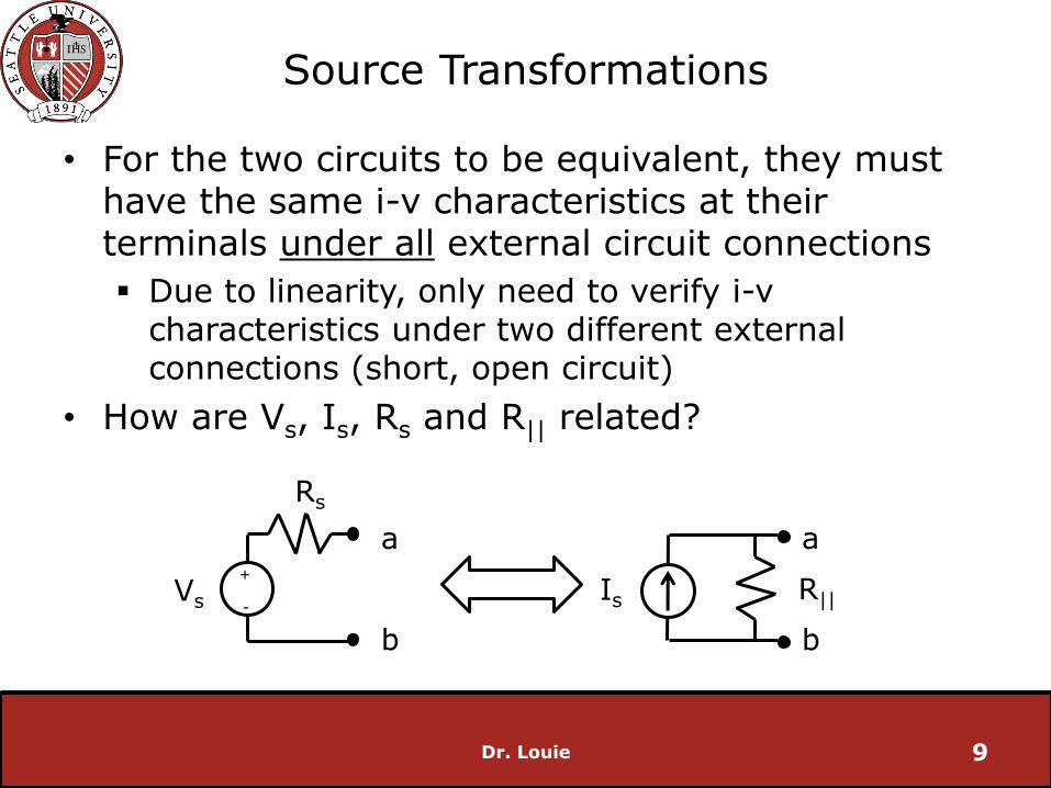
Source Transformations
• For the two circuits to be equivalent, they must have the same i-v characteristics at their terminals under all external circuit connections
Due to linearity, only need to verify i-v characteristics under two different external connections (short, open circuit)
• How are Vs, Is, Rs and R|| related?
Dr. Louie 9
+
- Vs
Rs
Is R||
a
b
a
b

Source Transformation
• Consider when the external circuit is a short
• Both circuits must have same short current out of their terminals
• Isc = Vs/Rs
• Isc = Is
• Therefore: Is = Vs/Rs
Dr. Louie 10
+
- Vs
Rs
Is R||
a
b
a
b
I I

Source Transformations
• Consider an open circuit
• Both circuits must same open circuit voltage Voc
• Voc = Vs
• Voc =R||Is
• Therefore: Is = Vs/R||
Dr. Louie 11
+
- Vs
Rs
Is R||
a
b
a
Voc
+
- Voc
+
- b

Source Transformations
• Relationships:
Is = Vs/R||
Is = Vs/Rs
• Therefore
• Rs = R|| = R
• Is = Vs/R
• Vs = IsR
Dr. Louie 12
+
- Vs
R
Is R
a
b
a
b
Source transformation equations

Source Transformations
• Verify the results hold for Circuit A and Circuit B
Dr. Louie 13
+ -
4V
2W 0.5W 1A
+ -
4V
2W
0.5W
0.5V +
-
Circuit A Circuit B

Example
• Use source transformations to find V0
Consider the current source first. Which resistor can we associate it with?
• 4W (they are in parallel)
Should we transform them?
• Yes, the resistor will be in series with the 2W resistor, and we can combine the two
Dr. Louie 14
+
-
2W 3W
8W 4W 12V 3A V0
+
-

Example
• Transform the source:
R = 4W
Vs = IsR = 3 x 4 = 12V
• Pay careful attention to the polarity
Dr. Louie 15
+
-
2W 3W
8W 12V 12V V0
+
-
+
-
4W
+
-
2W 3W
8W 4W 12V 3A V0
+
-

Example
• Transform the 12V source (on the right), if it is beneficial
Dr. Louie 16
+
-
3W
8W 12V 12V V0
+
-
+
-
6W
After combining series resistance
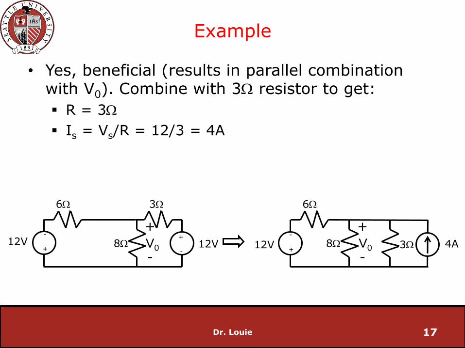
Example
• Yes, beneficial (results in parallel combination with V0). Combine with 3W resistor to get:
R = 3W
Is = Vs/R = 12/3 = 4A
Dr. Louie 17
+
-
3W
8W 12V 12V V0
+
-
+
-
6W
3W 8W 4A V0
+
-
6W
12V +
-

Example
• Now transform voltage source with 6W resistor
Dr. Louie 18
3W 8W 4A V0
+
-
6W
12V +
-

Example
• Result:
R = 6W
Is = Vs/R = 12/6 = 2A
Dr. Louie 19
3W 8W 4A V0
+
-
6W 3W 8W 4A V0
+
-
6W
12V +
-
2A
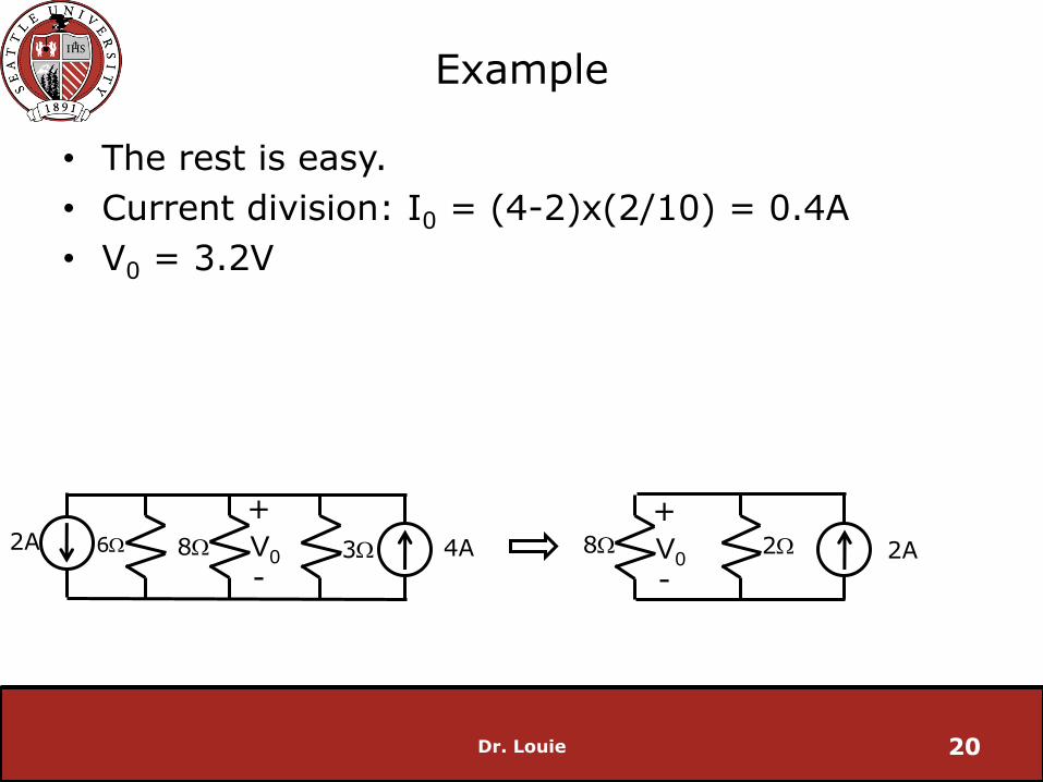
Example
• The rest is easy.
• Current division: I0 = (4-2)x(2/10) = 0.4A
• V0 = 3.2V
Dr. Louie 20
3W 8W 4A V0
+
-
6W 2A 2W V0
+
-
8W 2A

Source Transformations
• Dependent sources are handled using the same procedure
• Be careful
Dr. Louie 21

Thevenin’s Theorem
• Often, most elements of a circuit are fixed and only one element (the load) changes
• Do not want to re-solve the entire circuit every time the load changes
• Better approach: represent unchanging part of circuit with voltage source with series resistance
Dr. Louie 22
Vab
+
-
a
b
+ -
(Variable Resistor)
+
- VTH
RTH a
b

Thevenin’s Theorem
• Thevenin’s Theorem: a linear two-terminal circuit can be replaced by an equivalent circuit consisting of a voltage source in series with a resistor
• RTH: Thevenin Resistance
• VTH: Thevenin Voltage
Dr. Louie 23
+
- VTH
RTH
a
b
Linear Two-
Terminal Circuit
a
b
=

Thevenin’s Theorem
• How do we find VTH and RTH?
• One way: keep applying resistance and source transformations until there is a voltage source in series with a resistance between the terminals
Dr. Louie 24
a
b
+ -
+
- VTH
RTH a
b

Thevenin’s Theorem
• Better way: recognize that
VTH = VOC and
RTH = input resistance (looking into terminals a, and b), or RTH =VOC/ISC
Dr. Louie 25
a
b
+ -
+
- VTH
RTH a
b
VOC
+
-
Finding Thevenin Resistance
• No Dependent Sources:
short all voltage sources
open all current source
then find equivalent resistance RTH = Req
• Dependent Sources:
short all voltage sources
open all current source
Apply test voltage V0, compute current I0
RTH = V0/I0
Dr. Louie 26

Example
• Find the current through the load resistor if RL is 6, 16 and 36W
• Perfect situation for Thevenin Equivalent
Find Thevenin Equivalent, then solve equivalent circuit for various values of RL
Dr. Louie 27
a
b
+
- 32V 2A
4W 1W
12W RL
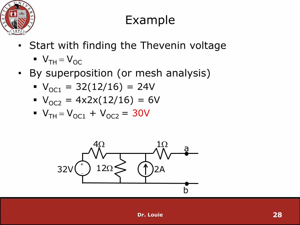
Example
• Start with finding the Thevenin voltage
VTH = VOC
• By superposition (or mesh analysis)
VOC1 = 32(12/16) = 24V
VOC2 = 4x2x(12/16) = 6V
VTH = VOC1 + VOC2 = 30V
Dr. Louie 28
a
b
+
- 32V 2A
4W 1W
12W

Example
• Now find the Thevenin resistance
RTH = Req
deactivate all sources
Req = 1 + (4x12)/16 = 4W
Dr. Louie 29
a
b
4W 1W
12W Req
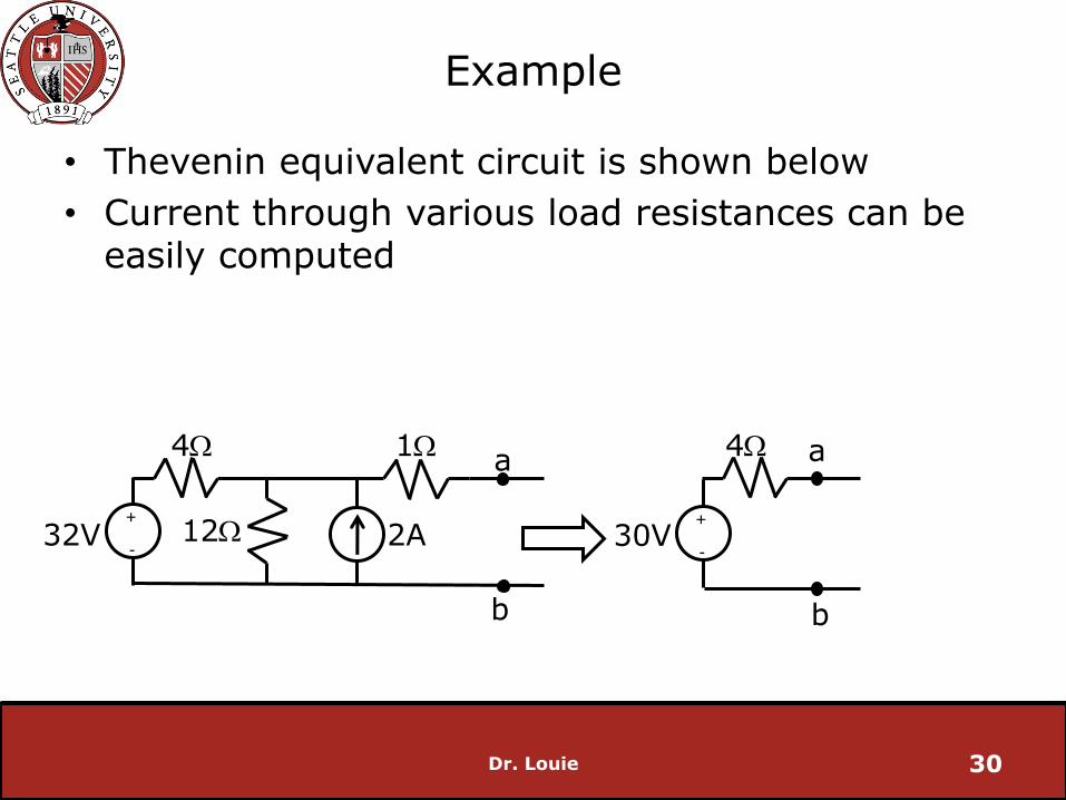
Example
• Thevenin equivalent circuit is shown below
• Current through various load resistances can be easily computed
Dr. Louie 30
+
- 30V
a
b
a
b
+
- 32V 2A
4W 1W
12W
4W

Example
• Find the Thevenin Equivalent of the circuit between the terminals a, b
Dr. Louie 31
a
b
+
- 30V 2A
60W
30W

Example
• Via superposition
VOC1 = 30x(30/90) = 10V
VOC2 = 30x2(60/90) = 40V
• VTH = VOC1 + VOC2 = 50V
Dr. Louie 32
a
b
+
- 30V 2A
60W
30W
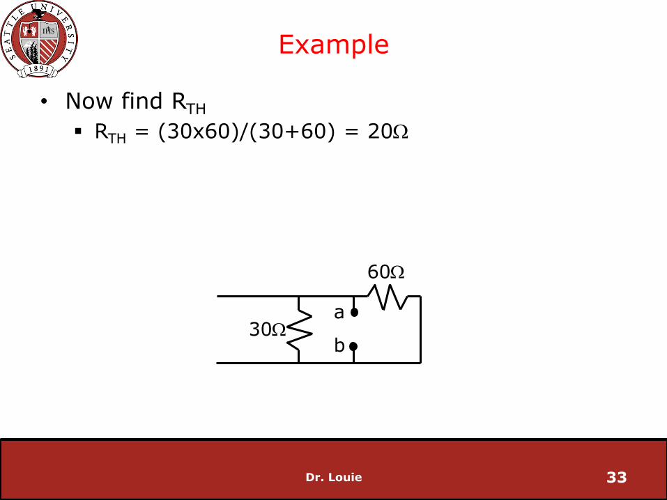
Example
• Now find RTH
RTH = (30x60)/(30+60) = 20W
Dr. Louie 33
a
b
60W
30W
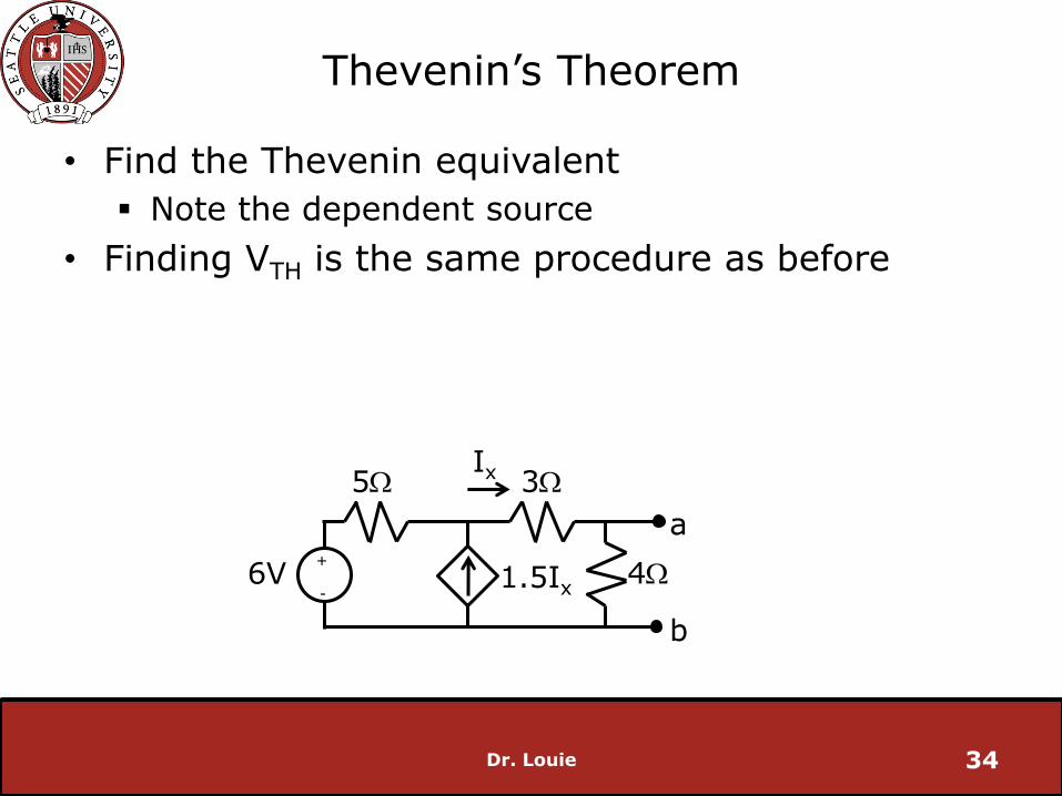
Thevenin’s Theorem
• Find the Thevenin equivalent
Note the dependent source
• Finding VTH is the same procedure as before
Dr. Louie 34
a
b
+
- 6V
3W
4W
5W
1.5Ix
Ix

Thevenin’s Theorem
• Mesh Analysis
6 = 5I1 + 7Ix (Supermesh)
1.5Ix + I1 = Ix (current source constraint equation)
Solving…
Ix = 1.33A
Therefore
VOC = 1.33x4 = 5.33V = VTH
Dr. Louie 35
a
b
+
- 6V
3W
4W
5W
Ix I1
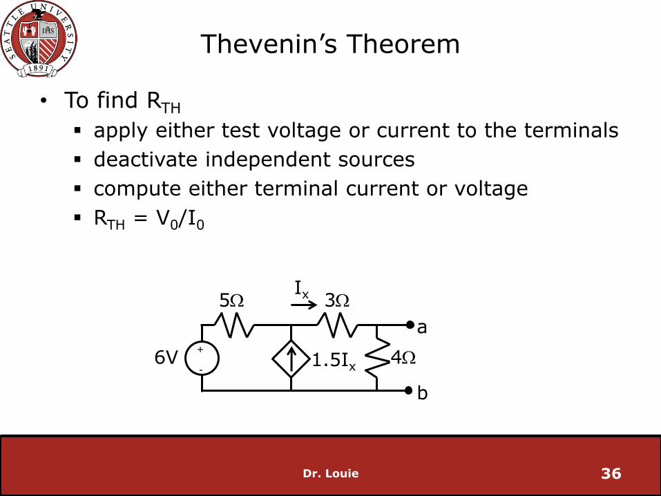
Thevenin’s Theorem
• To find RTH
apply either test voltage or current to the terminals
deactivate independent sources
compute either terminal current or voltage
RTH = V0/I0
Dr. Louie 36
a
b
+
- 6V
3W
4W
5W
1.5Ix
Ix

Thevenin’s Theorem
• Apply a test voltage V0
• Let V0 = 1V
• Now find I0 (note polarity if I0)
Dr. Louie 37
a
b
3W
4W
5W
1.5Ix
Ix
+
-
I0
V0

Thevenin’s Theorem
• I1 + 1.5Ix = Ix (Nodal Analysis)
I1 + 0.5Ix = 0
-0.2V1 + 0.5(V1 - 1)/3=0
-0.0333V1 – 0.16667 =0
V1=-5V
Ix = -2A (Ohm’s Law)
I2 = 0.25A (Ohm’s Law)
I0 = 2.25A (KCL)
Dr. Louie 38
a
b
3W
4W
5W
1.5Ix
Ix
+
- V0
I1
I2
I0

Thevenin’s Theorem
• Therefore RTH = V0/I0 = 1/2.25 = 0.444W
Dr. Louie 39
+
- 5.33V
0.444W a
b
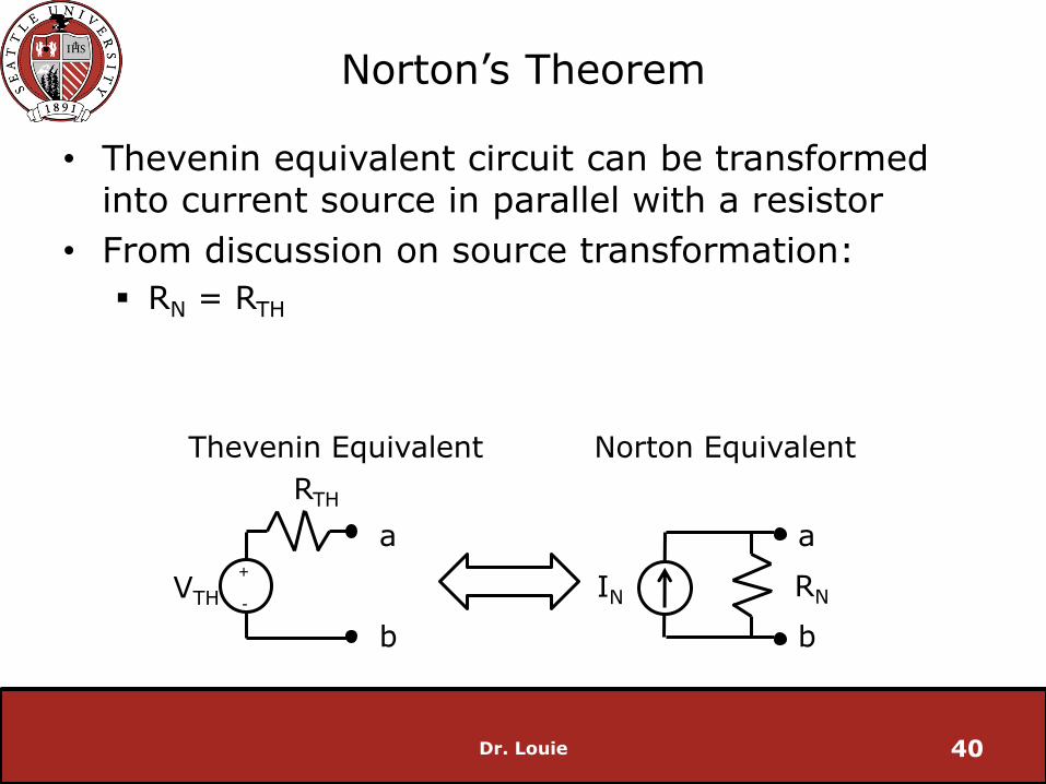
Norton’s Theorem
• Thevenin equivalent circuit can be transformed into current source in parallel with a resistor
• From discussion on source transformation:
RN = RTH
Dr. Louie 40
+
- VTH
RTH
IN RN
a
b
a
b
Norton Equivalent Thevenin Equivalent

Norton’s Theorem
• IN is found by shorting the terminals of the circuit
IN = ISC
Dr. Louie 41
IN ISC
a
b
Linear Two-
Terminal Circuit
a
b
IN
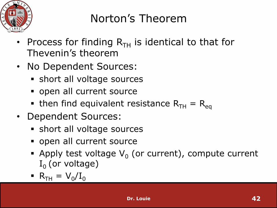
Norton’s Theorem
• Process for finding RTH is identical to that for Thevenin’s theorem
• No Dependent Sources:
short all voltage sources
open all current source
then find equivalent resistance RTH = Req
• Dependent Sources:
short all voltage sources
open all current source
Apply test voltage V0 (or current), compute current I0 (or voltage)
RTH = V0/I0
Dr. Louie 42

0 2 4 6 8 100
2
4
6
8
10
12
14
VL (
V)
RL (W)
Practical Sources
Dr. Louie 43
+
- 12V
RS
VL
+
-
Ideal source
Rs = 1W
Rs = 0.25W
0 20 40 60 80 1000
1
2
3
4
5
6
I L (
A)
RL (W)
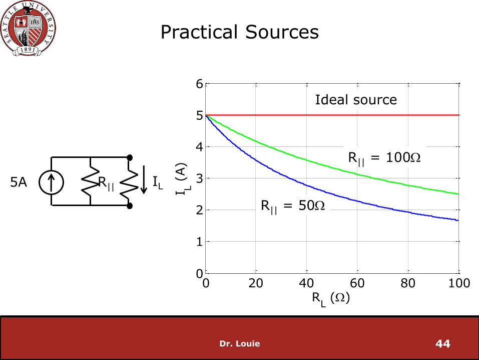
Practical Sources
Dr. Louie 44
IL
Ideal source
R|| = 100W
5A R||
R|| = 50W


![Combining Source-to-Source Transformations and Processor ...homepages.inf.ed.ac.uk/npt/pubs/lctes-07.pdf · Earlier efforts [13] to combine code transformation and ISE have been targeted](https://img.pdfslide.net/doc/110x75/5f57c19f95d167585809ae42/combining-source-to-source-transformations-and-processor-earlier-efforts-13.jpg)