Embed Size (px)
Citation preview
Design Guidelines & Procedures Version 22.1 ©
September 2021 Page 1 of 230
1.00 TableofContents
Modifications ..................................................................................................................................... 12 1.00 .. Interpretation and Definitions 13
Purpose of this document ......................................................................................................... 13 Use of this document ................................................................................................................ 13 Abbreviations ............................................................................................................................ 13 Australian Standards ................................................................................................................ 14 Mandatory requirement ............................................................................................................. 14 Guideline requirement .............................................................................................................. 14 Departures from the requirements of this document ................................................................ 14 Contractor ................................................................................................................................. 14 Consultant ................................................................................................................................. 14 Equal & Approved ..................................................................................................................... 14 Legislation ................................................................................................................................. 15
2.00 .. Planning & Design Controls 16 Site Planning Controls .............................................................................................................. 16 Whole of Life Considerations .................................................................................................... 16 Crime Prevention Through Environmental Design (CPTED) ................................................... 16 Design for Bushfire-prone Areas .............................................................................................. 17 Design for People with Disabilities ........................................................................................... 17 Building Height .......................................................................................................................... 18 Wind around Buildings .............................................................................................................. 18 Fire Engineering Design Brief ................................................................................................... 18 Daylighting ................................................................................................................................ 18 Space Guidelines ...................................................................................................................... 18 Plant Rooms ............................................................................................................................. 20 Cleaner’s Store ......................................................................................................................... 20 Facilities Store .......................................................................................................................... 20 Valve Room .............................................................................................................................. 20 Electrical Riser Cupboard ......................................................................................................... 20 Telecommunications Equipment Rooms .................................................................................. 20 Waste Collection and Gas Bottle Storage ................................................................................ 21 Corridors ................................................................................................................................... 21 Links to Adjacent Buildings ....................................................................................................... 21 Vending Machines .................................................................................................................... 21 End of Trip Facilities ................................................................................................................. 21 Toilets ....................................................................................................................................... 21 Shower & Baby Change Facilities ............................................................................................ 22 Parenting Room ........................................................................................................................ 22 Collaborative Learning & Study Centres .................................................................................. 22 Lecture Theatres, Auditoria & Other Teaching Spaces ............................................................ 23 Video Conferencing Rooms ...................................................................................................... 23 Laboratories .............................................................................................................................. 23 Building Areas & Definitions ..................................................................................................... 24 Building Efficiency ..................................................................................................................... 25 Acoustic Requirements for Internal Spaces ............................................................................. 25 Asbestos & PCBs ..................................................................................................................... 28 Design for Safety in Maintenance & Use .................................................................................. 28
3.00 .. Designing for Sustainability 30 General ..................................................................................................................................... 30 Sustainability Principles ............................................................................................................ 30 Energy Simulation (mandatory requirement) ............................................................................ 32 Building Management System .................................................................................................. 32 Sustainable Design Compliance Matrix .................................................................................... 32
4.00 .. Section deleted refer to RFT documents 33
Design Guidelines & Procedures Version 22.1 ©
September 2021 Page 2 of 230
5.00 .. Building Structure 34 Generally................................................................................................................................... 34 Floor to Floor Heights ............................................................................................................... 34 Location of Columns ................................................................................................................. 34 Slabs 34 Structural Walls ......................................................................................................................... 35 Tanking ..................................................................................................................................... 35 Termite Control ......................................................................................................................... 35
6.00 .. Staircases & Ramps 36 Generally................................................................................................................................... 36 Internal Stairs ............................................................................................................................ 36 External Stairs and Ramps ....................................................................................................... 36 Handrails ................................................................................................................................... 36 Finishes..................................................................................................................................... 36 Tactile Ground Surface Indicators (TGSIs) .............................................................................. 37
7.00 .. Roofs 39 Roofs Generally ........................................................................................................................ 39 Roof Deck Materials ................................................................................................................. 39 Flashings and Cappings ........................................................................................................... 39 Roof Insulation .......................................................................................................................... 40 Gutters ...................................................................................................................................... 40 Downpipes ................................................................................................................................ 40 Roof Access & Walkways ......................................................................................................... 41 Roof Safety System .................................................................................................................. 41
8.00 .. External Walls 42 Generally................................................................................................................................... 42 Construction .............................................................................................................................. 42 In-situ Finishes .......................................................................................................................... 42 Applied Finishes ....................................................................................................................... 42 Colours ...................................................................................................................................... 43 Sun Shading & Screening......................................................................................................... 43 Provision for Building Signage .................................................................................................. 43 Sealants .................................................................................................................................... 43 External Protection ................................................................................................................... 43
9.00 .. Windows 44 Generally................................................................................................................................... 44 Design Criteria .......................................................................................................................... 44 Window Styles .......................................................................................................................... 44 Window Framing ....................................................................................................................... 44 Glazing ...................................................................................................................................... 44 Window Locks ........................................................................................................................... 45 Window Cleaning ...................................................................................................................... 45 Window Curtains & Blinds ........................................................................................................ 45 Teaching Spaces ...................................................................................................................... 45
10.00 Internal Walls & Partitions 46 Generally ................................................................................................................................ 46 Masonry Walls ........................................................................................................................ 46 Framed Partitions & Linings ................................................................................................... 46 Linings to Masonry Walls ....................................................................................................... 47 Wall Protection ....................................................................................................................... 47 Acoustics ................................................................................................................................ 47 Projection Walls ..................................................................................................................... 47 Operable Walls ....................................................................................................................... 48 Glazed Partitions & View Panels............................................................................................ 48 Toilet Cubicle Partitions ......................................................................................................... 48 Sealing Penetrations .............................................................................................................. 48
11.00 Doors & Hardware 50 Aluminium Framed & Glazed Doors ...................................................................................... 50
Design Guidelines & Procedures Version 22.1 ©
September 2021 Page 3 of 230
External Doors ....................................................................................................................... 50 Internal Doors ......................................................................................................................... 50 Fire Doors ............................................................................................................................... 51 Frames ................................................................................................................................... 51 Hinges .................................................................................................................................... 51 Locks ...................................................................................................................................... 51 Door Furniture ........................................................................................................................ 52 Door Closers .......................................................................................................................... 52 Electro Magnetic Hold-Open Devices .................................................................................... 53 Kick Plates .............................................................................................................................. 53 Door Stops ............................................................................................................................. 53 Cabin Hooks ........................................................................................................................... 53 Security Door Viewer ............................................................................................................. 53 Acoustic Seals ........................................................................................................................ 53 Automatic & Special Door Operating Systems ...................................................................... 53 Keying System & Keys ........................................................................................................... 54
12.00 Wall Finishes 55 Generally ................................................................................................................................ 55 Paint Finishes, Materials ........................................................................................................ 55 Paint Finishes, Workmanship ................................................................................................. 55 Paint Systems ........................................................................................................................ 56 Paint Colours .......................................................................................................................... 56 Ceramic Wall Tiles ................................................................................................................. 56 Sealants ................................................................................................................................. 56 Decorative Wall Finishes ........................................................................................................ 57 Acoustic Wall Finishes ........................................................................................................... 57 Chair Rails .............................................................................................................................. 57 Built-in Artwork ....................................................................................................................... 57
13.00 Floor Finishes 58 Colours ................................................................................................................................... 58 Carpet Finishes ...................................................................................................................... 58 Vinyl Finishes ......................................................................................................................... 59 Vinyl Skirtings ......................................................................................................................... 59 Ceramic Tile Finishes ............................................................................................................. 59 Nosings, Junctions & Trims .................................................................................................... 60 Door Mats ............................................................................................................................... 60 Plant Room............................................................................................................................. 60 Thresholds .............................................................................................................................. 61 Access Floors ......................................................................................................................... 61 Alternative Finishes ................................................................................................................ 61 Tactile Indicators .................................................................................................................... 61
14.00 Ceilings 62 Generally ................................................................................................................................ 62 Mineral Fibre Tile Suspended Ceiling Systems ..................................................................... 62 Vinyl Faced Fibre Cement Tile Suspended Ceilings ............................................................. 62 Flush Plasterboard Ceilings ................................................................................................... 62 Ceiling Mounted Fixtures ....................................................................................................... 63 External Soffit Linings ............................................................................................................ 63 Plant Room Ceilings ............................................................................................................... 63 Equipment and Servicing Access .......................................................................................... 63 Pelmets .................................................................................................................................. 63 Timber Feature Ceilings ......................................................................................................... 63
15.00 Fitments 65 Generally ................................................................................................................................ 65 Whiteboards & Pinboards ...................................................................................................... 65 Bookshelves ........................................................................................................................... 66 Notice Boards ......................................................................................................................... 66 Projection Screens ................................................................................................................. 66
Design Guidelines & Procedures Version 22.1 ©
September 2021 Page 4 of 230
Built-in Joinery Generally ....................................................................................................... 66 Lecture Theatres .................................................................................................................... 67 Seminar & Computer Teaching Rooms ................................................................................. 67 Video Conferencing Rooms ................................................................................................... 67 Collaborative Learning & Study Centres ................................................................................ 67 Kitchenettes & Tea Preparation Stations ............................................................................... 68 Laboratories ........................................................................................................................... 68 Monitor Brackets .................................................................................................................... 69 Compactus Units .................................................................................................................... 69 Toilets ..................................................................................................................................... 69 Hand Wash Stations .............................................................................................................. 70 Coat Hooks............................................................................................................................. 70 Mail Boxes, Assignment Boxes, Enquiry Counters ................................................................ 71 Bag Racks or Hooks .............................................................................................................. 71 Waste & Recycle Bin Enclosures ........................................................................................... 71 Drinking Fountains ................................................................................................................. 71 Works of Art............................................................................................................................ 71
16.00 Audio Visual Services 72 General ................................................................................................................................... 72 Systems Design ..................................................................................................................... 72
.... General Principles 72 .... Audiovisual System Design Documentation 73
Systems Installation ............................................................................................................... 73 .... Program 73 .... Acceptable Specialist AV Subcontractors 73 .... Installation of Cables 73 .... Equipment Installation Practices 74
Control System ....................................................................................................................... 74 .... General Requirements 74 .... System Programs 74 .... User Instruction Panel 75
Master Antennae Television (MATV) and Cable Television distribution ................................ 75 .... General Requirements 75 .... Testing and proof of performance 75
Audio Visual Cabling .............................................................................................................. 75 .... Cabling Locations 75 .... Conduits for AV Cabling 75 .... Cable Types 76 .... Connectors & Terminals 76 .... Services Required in Teaching/Meeting spaces 76 .... Telephones in teaching/meeting spaces 76
Video/Data Projection ............................................................................................................ 77 Linkable Rooms ..................................................................................................................... 77 Audio Systems ....................................................................................................................... 77 Hearing Augmentation ........................................................................................................... 77 Video Conferencing ................................................................................................................ 78 Registration of AV Assets ...................................................................................................... 78
17.00 Hydraulic Services 79 General Requirements ........................................................................................................... 79
.... Scope of Hydraulic Services 79 .... Underground Pipework & Valves 79 .... Reticulation Pipework & Valves 79 .... Pipework Support 80 .... Floor Penetrations 80 .... Service Ducts 80 .... Laboratory Services 80 .... Identification of Pipework 80
Sewer Drainage ..................................................................................................................... 81
Design Guidelines & Procedures Version 22.1 ©
September 2021 Page 5 of 230
.... Materials 81 .... Pipe Sizing 81 .... Inspection Chambers 81 .... Inspection Openings & Floor Wastes 81 .... Trade Waste 81 .... Greywater Systems 81
Stormwater Drainage ............................................................................................................. 81 .... Materials 81 .... Pipe Sizing 82 .... Discharge 82 .... Inspection pits 82 .... Grated Drains 82
Sanitary Fixtures .................................................................................................................... 82 .... Standard Fixtures 82 .... Laboratory Sinks 83
Taps ....................................................................................................................................... 83 .... Standard Taps 83 .... Laboratory Safety Showers 84
Soil, Waste & Vent Plumbing ................................................................................................. 84 .... Materials 84 .... Pipework Installation 84 .... Access 84 .... Condensate Waste Pipework 85 .... Installation of Waterless Urinals 85 .... Venting 85
Water Reticulation Generally ................................................................................................. 85 .... Water Systems 85 .... Pipe materials 85 .... Pipe Fittings and Jointing 85 .... Valves 85 .... Back Flow Prevention 86
Cold Water Service ................................................................................................................ 86 Hot Water Service .................................................................................................................. 86 Hot Water Generation Systems ............................................................................................. 87
.... General Hot Water 87 .... Laboratories 87 .... Hot Water Systems 87
External Hose Cocks .............................................................................................................. 88 Pumps .................................................................................................................................... 88 Water Meters .......................................................................................................................... 89 Rainwater Collection, Storage & Reticulation ........................................................................ 89 BMS Control & Alarm Points .................................................................................................. 90 Inspection & Testing ............................................................................................................... 90
.... General Requirements 90 .... Testing Pressures 90
Sewerage Pump Stations ....................................................................................................... 90 Hydraulic Equipment Identification and Asset Data ............................................................... 91
18.00 Mechanical Services 92 Air conditioning & Ventilation ................................................................................................. 92
.... General Requirements 92 .... Specific Requirements 93 .... Design Conditions & Performance Standards 94 .... Noise and Vibration control 95 .... Equipment, Warranties & Maintenance 95 .... Piping, Valves & Fittings 95 .... Insulation to Pipework 96 .... Ductwork & Registers 97 .... Plant & Equipment 98
Design Guidelines & Procedures Version 22.1 ©
September 2021 Page 6 of 230
.... Air-Conditioning Electrical System 101 .... Identification of Pipework & Ductwork 102 .... Future Expansion & Construction 102 .... Building Management System (BMS) 102 .... De-humidification Control 104 .... Time Schedule Requirements 105 .... Control – Ventilation Fans 106 .... Control – Ceiling Fan Coil Units 106 .... Control – Variable Air Volume Boxes (VAV’s) 106 .... Control – Air Handling Units (AHUs) 107 .... Control – Chilled water 108 .... Underground Services 110 .... Outside Air Fans 110 .... Water Metering 110 .... Graphics Pages 110 .... Energy Management 111 .... Air Conditioning Cooling & Heating Design Setpoints & Control Philosophy 111 .... Design Requirements for VAV Air Conditioning Systems 112
Fume Cupboards ................................................................................................................. 113 .... General Requirements 113 .... Fume Cupboards Generally 113 .... Fume Cupboard Construction 113 .... Fume Cupboard Services 114 .... Fume Cupboard Support 114 .... Sash Activated Velocity Control 114 .... Control Systems 114
Fume Exhaust Systems ....................................................................................................... 115 .... Noise & Vibration 115 .... Exhaust Unit 115 .... Exhaust Fume Scrubbing 115 .... Air-Conditioned Make-up Air Supply 116 .... Fume Exhaust Ductwork 116 .... Electrical & Controls 116 .... Dangerous Goods & Safety Storage Cabinets 117 .... Nederman Arm Extraction Systems 117
Laboratory Piped Services ................................................................................................... 118 .... LP Gas 118 .... Laboratory Gases 118 .... Compressed Air 118 .... Vacuum 119 .... Reverse Osmosis Water 119 .... Isolation of Piped Services 120 .... Outlets to Piped Services 120 .... Identification of Pipework 120 .... BMS Alarm Points 120
Commissioning and Handover ............................................................................................. 120 .... General Requirements 120 .... Fume Cupboards 121 .... Piped Services 121
Depiction of Airflows on Mechanical Drawings for Consultants & Contractors .................... 122 .... Requirements for Depiction of Airflows on Mechanical Design & ‘As Constructed’
Drawings ... 122 .... Requirements for Airflow Schematics for Special Mechanical Systems 122
Water Meters for Cooling Towers ........................................................................................ 122 Mechanical Equipment Identification ................................................................................... 122
19.00 Fire Services 132 Generally .............................................................................................................................. 132 Basic Requirements for Fire Detection & Alarm Systems ................................................... 132
Design Guidelines & Procedures Version 22.1 ©
September 2021 Page 7 of 230
Fire Services Contractor Qualifications ................................................................................ 132 General Equipment Requirements ....................................................................................... 132 Fire Indicator Panels (FIP) ................................................................................................... 133 Detection Systems ............................................................................................................... 133 Visual Alarm Indicators ........................................................................................................ 134 Fire Services Wiring ............................................................................................................. 134 Hydraulic Fire Services ........................................................................................................ 134
.... Water Supply 134 .... Pipe Materials 135 .... Hydrants 135 .... Hose Reels 136 .... Fire Hydrant and Hose Reel Travel Paths 136 .... Fire Sprinklers 136 .... Testing 136 .... Fire Extinguishers 136 .... Fire Blankets 137
Special Fire Systems ........................................................................................................... 137 Door Hold Open Devices ..................................................................................................... 137 Door Control ......................................................................................................................... 137 Smoke Exhaust Systems ..................................................................................................... 137 Fume Cupboards ................................................................................................................. 137 Fire Hazard Indices .............................................................................................................. 137 Hazchem Signage ................................................................................................................ 138 Emergency Services Vehicle Access ................................................................................... 138 Inspections & Documentation .............................................................................................. 138
20.00 Electrical Services 139 Demolition ............................................................................................................................ 139 External Lighting .................................................................................................................. 139 Internal Lighting .................................................................................................................... 140 Lighting Control .................................................................................................................... 141
.... Spaces with AMX AV Control 144 High Voltage ......................................................................................................................... 144
.... Design 144 .... Installation 144
Low Voltage.......................................................................................................................... 144 .... Distribution 144 .... General Power 145 .... Emergency Stops 146
Backup Power ...................................................................................................................... 146 .... Strategy 146 .... Uninterruptible Power Supply 147 .... Prioritisation 147 .... Equipment-based prioritisation 148 .... Area-based prioritisation 148 .... Additional considerations 149
Switchboards ........................................................................................................................ 149 .... Main Switchboard 150 .... Distribution Boards 151 .... Current Schedules & Diagrams 151 .... Circuit Breakers 151 .... Cable Numbering 151
Telecommunications Equipment Room (TER) ..................................................................... 152 Metering ............................................................................................................................... 152
.... Context 152 .... What to Meter 153 .... Meter Types 153 .... Installation 153 .... Metering Communications 155
Design Guidelines & Procedures Version 22.1 ©
September 2021 Page 8 of 230
Power Quality ....................................................................................................................... 155 Cabling ................................................................................................................................. 155
.... Types & Sizes 155 .... Cable Entries 155 .... Containment 156 .... Installation 156
Emergency Evacuation Lightning ........................................................................................ 157 Lighting Protection ............................................................................................................... 157 Clocks ................................................................................................................................... 158 Underground Electrical Services .......................................................................................... 158 Testing .................................................................................................................................. 158 Product Substitution ............................................................................................................. 159 Plant and Equipment ............................................................................................................ 159 Warranty ............................................................................................................................... 159 Renewable Energy Systems ................................................................................................ 159
.... Renewable Energy Equipment Identification and Asset Data 159 .... Inverters 160 .... Solar Panels 160 .... Communication 161 .... Roof Placement 161 .... Other 161
Electrical Design Requirements ........................................................................................... 161 .... 163
Deliverables 163 21.00 Communication & Data Services 164
System Generally ................................................................................................................. 164 Subsystems .......................................................................................................................... 164 General Requirements All Systems ..................................................................................... 164
.... Types of Use 164 .... Standards Conformance 165 .... Other Requirements 166 .... Performance Warranties, Guarantees & Auditing 168 .... Scheduling 168 .... Refurbishments of Minor Internal Works 168
Work Area Subsystem ......................................................................................................... 169 .... Materials 169 .... Installation Practices 169
Horizontal Subsystem .......................................................................................................... 169 .... Materials 169 .... Mechanical Protection of Cables 171 .... Cable Ducts 171 .... Cable Supports 171 .... Cable Hangers 171 .... Conduits 171 .... Separation 172 .... Installation Practices 172 .... Identification Requirements 173
Riser Subsystem .................................................................................................................. 174 Administration Subsystem .................................................................................................... 174
.... Generally 174 .... Materials 174 .... Mechanical protection 175 .... Method of Administration 175 .... Identification 175
Equipment Subsystem ......................................................................................................... 175 .... Materials 175 .... Mechanical Protection 176 .... Installation Procedure 176
Design Guidelines & Procedures Version 22.1 ©
September 2021 Page 9 of 230
Campus Subsystem ............................................................................................................. 176 .... Materials 176 .... Mechanical Protection of Cables 177 .... Installation Procedures 177
Design Criteria for New Buildings ........................................................................................ 178 .... Generally 178 .... Telecommunications Equipment Rooms (TER) 178 .... Telecommunication Risers 180 .... Campus Subsystem 180 .... Riser Subsystem 181
Standard Documentation & Labelling Requirements ........................................................... 181 Building Control Systems ..................................................................................................... 181
.... Generally 181 .... Early Data Network Provisioning for BCS 182
Wireless Networks ............................................................................................................... 182 Particular Telecommunications & Data Requirements – Teaching Spaces ........................ 183
.... Lecture Theatres 183 .... Seminar & Computer Teaching Rooms, Other Specialist Teaching Spaces 183 .... Video Conferencing Rooms 183 .... Learning Centres 184
Power over Ethernet Clocks ................................................................................................. 184 Space Utilisation & Occupancy Monitoring .......................................................................... 184 Mobiles Infrastructure ........................................................................................................... 185 Reference documents .......................................................................................................... 185
22.00 Security Services 186 Generally .............................................................................................................................. 186 Electronic Access Control System (EAC) ............................................................................ 186 Closed Circuit Television (CCTV) System ........................................................................... 186
.... Generally 186 .... System Standard 186 .... System Components 187 .... System Control Equipment 187 .... Cameras 187 .... Power Supply 187 .... Cabling Requirements 187 .... Equipment Locations & Installation 187
Security Phones ................................................................................................................... 188 Carpark Barrier Gates .......................................................................................................... 188
23.00 Lifts 189 Lift Contracts ........................................................................................................................ 189 New Project Lift Design ........................................................................................................ 189 Existing Project Lift Design .................................................................................................. 189 Lift Energy Efficiency ............................................................................................................ 190 Provision for People with Disabilities ................................................................................... 190 Keying System & Keys ......................................................................................................... 190 Lift Car Finishes ................................................................................................................... 191 Landings ............................................................................................................................... 192 Lift Pits and Lift Shafts ......................................................................................................... 192 Machinery Room/Machinery Space ..................................................................................... 193 Lift Performance ................................................................................................................... 193 Telephone ............................................................................................................................ 194 Emergency Lowering Power Pack ....................................................................................... 194 Workshop Drawings ............................................................................................................. 194 ‘As Constructed’ Drawings ................................................................................................... 194
24.00 Landscaping 195 Generally .............................................................................................................................. 195 Red Imported Fire Ants (RIFA) ............................................................................................ 195 Water Supply to Hosecocks, Drinking Fountains and Irrigation Systems ............................ 195
Design Guidelines & Procedures Version 22.1 ©
September 2021 Page 10 of 230
Hosecocks ............................................................................................................................ 195 Landscape Drainage ............................................................................................................ 195 Topsoil & Planting Soil ......................................................................................................... 195 Turf 196 Planting ................................................................................................................................ 196 Garden Mulch ....................................................................................................................... 196 Landscape Timber ............................................................................................................... 197 Garden Edges ...................................................................................................................... 197 Retaining & Planter Box Walls ............................................................................................. 197 Paving & Footpaths .............................................................................................................. 197 Irrigation System Generally .................................................................................................. 198 Irrigation System Materials & Equipment ............................................................................. 198 Irrigation System Installation ................................................................................................ 199 Landscape Furniture ............................................................................................................ 201 Supervision of Landscaping Work ....................................................................................... 201 The Landscape Maintenance Period ................................................................................... 201 External Signage .................................................................................................................. 202
25.00 Signage 203 Generally .............................................................................................................................. 203 Responsibilities of Design Consultants for Signage ............................................................ 203 Departures from the Signage Manual .................................................................................. 203 Statutory Signage ................................................................................................................. 203 Braille and Tactile Signage .................................................................................................. 203 Special Signage ................................................................................................................... 203 Standard Signage Drawings ................................................................................................ 204
26.00 Loose Furniture & Equipment 205 Generally .............................................................................................................................. 205 Specialist Furniture .............................................................................................................. 205 Furniture Suppliers ............................................................................................................... 205 Timber Furniture Requirements ........................................................................................... 205 Chairs ................................................................................................................................... 206 Seminar Room Furniture ...................................................................................................... 206 Learning Centre Furniture .................................................................................................... 206 External Furniture ................................................................................................................. 206 Metal Furniture ..................................................................................................................... 207
27.00 Post Construction Responsibilities of Consultants & Contractors 208 Generally .............................................................................................................................. 208 Preventative Maintenance .................................................................................................... 208 Guarantees & Warranties ..................................................................................................... 208 Operating & Maintenance Manuals ...................................................................................... 208 ‘As Constructed’ Drawings ................................................................................................... 209 Post Construction Site Survey ............................................................................................. 212 Permanent Survey Marks ..................................................................................................... 212
28.00 Project Briefing & Procurement 213 Generally .............................................................................................................................. 213 The Strategic Objective Brief ............................................................................................... 213 Structure & Content of the Strategic Objective Brief ............................................................ 213
.... Overview & Purpose 214 .... Design Intent 215
Technical Brief ..................................................................................................................... 215 Capital Works Procurement ................................................................................................. 216
29.00 Design Procedures for Consultants & Contractors 217 Generally .............................................................................................................................. 217 Consultant ............................................................................................................................ 217 Contractor ............................................................................................................................. 217 Selection of Consultants for ‘Traditional’ Contracts ............................................................. 217 Selection of Consultants for D&C Contracts ........................................................................ 218 Conditions of Engagement ................................................................................................... 219
Design Guidelines & Procedures Version 22.1 ©
September 2021 Page 11 of 230
Information to be provided to Consultants & Contractors by CLF ....................................... 219 Project Control Group .......................................................................................................... 220 Traditional Contracts, Particular Requirements & Procedures ............................................ 220 D&C Contracts, Particular Requirements & Procedures ..................................................... 222 Documentation Format ......................................................................................................... 222 Technical requirements for CAD Drawings .......................................................................... 223 Site Survey & Photographic Record .................................................................................... 224 Communication with GU Project Personnel ......................................................................... 225 Document Review and Compliance with the GU Design Guidelines................................... 225 Building Services Plans of Altered Existing Buildings .......................................................... 225 Practical Completion ............................................................................................................ 225 Work Opportunities for GU Students ................................................................................... 226
30.00 Certification under the Building Act at Griffith University 227 Background .......................................................................................................................... 227 Obtaining Building Approval ................................................................................................. 227 Process for Obtaining Building Approval ............................................................................. 227 Queensland Fire and Emergency Services Approvals ........................................................ 228 Health Approvals .................................................................................................................. 228 Sewerage and Water Supply Approval ................................................................................ 228
31.00 Standard Drawings 229
Design Guidelines & Procedures Version 22.1 ©
September 2021 Page 12 of 230
Modifications
Version Issue Date Amended Sections / Clause(s) Comment 22.1 September 2021 Sections:
4.00 – Project Preliminaries – Deleted 20.00 – Electrical Services – significant rewrite 27.00 – 27.04 Operating & Maintenance Manuals –reference to hard copy records has been deleted 27.00 – 27.05 ‘As Constructed’ Drawings – reference to hard copy records has been deleted 27.00 – 27.06 Post Construction Site Survey – minor additional requirements 29.00 – 29.11 Documentation Format – reference to hard copy records has been deleted. 32.00 – Standard Forms – Deleted
All additions and changes are highlighted Yellow in individual sections.
Design Guidelines & Procedures Version 22.1 ©
September 2021 Page 13 of 230
1.00 Interpretation and Definitions
Purpose of this document These Design Guidelines & Procedures are intended to state Griffith University’s Mandatory and Minimum requirements for the design and construction of its buildings and facilities. Throughout the Sections of this document, it will be clearly defined when a requirement is Mandatory, otherwise any requirement is a ‘Guideline’ only. The Procedures outlined in this document are intended to facilitate expeditiously and efficiently, the process of all necessary approvals through the relevant departments of the University.
Use of this document
This document does not relieve any person or company commissioned by or contracted to Griffith University or its appointed Design & Construction Managers, from the preparation of comprehensive Specifications for inclusion in Tender or Construction documentation. Such persons or companies should incorporate the requirements contained in the various Sections of this document, as appropriate, in the preparation of those Specifications, but no part of this document should be issued in tender or construction documentation as a substitute for a Specification.
Abbreviations The following abbreviations are used throughout in this document;
AS Australian Standard
CLF Campus Life (the element of the GU’s Corporate Services responsible for campus development)
D&C Design & Construct
DS Digital Solutions, Corporate Services
ES Engineering Services, Corporate Services
ESA Enterprise & Solution Architecture (Division of DS)
FM Facilities Management, Corporate Services
GU Griffith University (the Principal under all Agreements and Contracts)
ITI Information Technology Infrastructure & Cloud (Division of DS)
NCC National Construction Code Series (incorporating the Building Code of Australia (BCA) and the Plumbing Code of Australia (PCA)
NCS Network & Collaboration Services (Division of DS)
FIN Finance, Corporate Services
PD&C Planning, Design & Construction, Corporate Services
SDF Space Description Form
WHS Work, Health & Safety
Design Guidelines & Procedures Version 22.1 ©
September 2021 Page 14 of 230
Australian Standards Wherever an Australian Standard (AS) exists which impacts on any matter pertaining to the design, construction, operation or maintenance of the facility, the AS shall set the minimum criteria to be applied to the project. If the Principal requires a higher standard as outlined later in this document or stated in a Project Brief, the Principal’s requirement shall take precedence. Assumptions as to acceptable Standards should not be made. Where a AS is called upon by the NCC or other relevant legislation, the requirements of that AS shall be delivered or exceeded as required by these Guidelines.
Mandatory requirement Where a requirement is designated in this document as being Mandatory, generally no alternative design, specification, material or manufacturer will be entertained by the University, and the requirement shall be incorporated into the documentation or construction without variation. Consultants or Contractors may offer alternative innovative solutions to these Mandatory requirements for consideration and analysis by PD&C and the appropriate technical divisions within GU. No such alternative solution may proceed to design or construction without the written approval of the Principal.
Guideline requirement If a requirement is not designated as mandatory, GU will consider alternative designs, specifications, materials or manufacturers, provided that the alternatives satisfy the minimum standards for that requirement as outlined in this document.
Departures from the requirements of this document Departures from these Design Guidelines & Procedures, or any applicable AS, if allowed, must be confirmed in writing by the Principal. Any departure made without such confirmation, which is incorporated into the design or construction of a project, shall be rectified at no cost to GU.
Contractor The term ‘Contractor’ where used throughout this document shall mean either the Contractor appointed after competitive tendering for ‘Traditional’ Lump Sum Fixed Price Contracts, or the Design & Construct (D&C) Manager appointed for ‘Non Traditional’ design and construction management Contracts.
Consultant The term ‘Consultant’ where used throughout this document shall mean any design or technical consultant including but not limited to Architects, Engineers, Surveyors, Quantity Surveyors etc. and any other individual or firm providing its services on a project either appointed directly under an Agreement with GU or employed by a ‘Contractor’ who has been appointed by GU to undertake the design and construction management of a project.
Equal & Approved Wherever a brand or manufacturers’ name appears in this document, an alternative brand or manufacturer will only be permitted if that brand or manufacturer can satisfy all the requirements of this document, the drawings and specifications. Prior approval must be sought from PD&C before incorporating such alternatives into the design and documentation for the project. Any approved alternative must be installed strictly in accordance with the manufacturers’ printed instructions. Unapproved alternatives will be removed and replaced with complying materials, plant or equipment at no cost to GU.
Design Guidelines & Procedures Version 22.1 ©
September 2021 Page 15 of 230
Legislation
Griffith University operates under the authority of the Griffith University Act and its subordinate statutes, rules and regulations. Penalties for offences under this Act are enforceable under Queensland Law. In addition to any monetary penalties which may be imposed under legislation, or any Conditions of Contract, persons who wilfully disregard the requirements for care and maintenance of any element of a GU campus, will be liable to removal from that campus.
Design Guidelines & Procedures Version 22.1 ©
September 2021 Page 16 of 230
2.00 Planning & Design Controls All the requirements of this Section are Mandatory.
Site Planning Controls The University has approved Master Plans for all of its Campuses. Potential building development is an essential element of these Plans, and they indicate zones where buildings may be built on all Campuses. These Master Plans undergo periodic review, and copies the current version of each Plan are available upon request from PD&C.
Whole of Life Considerations It is imperative to ensure that all facilities constructed incorporate sustainability, life-cycle costs and maintainability in their design. Designs and installations must embrace and make adequate provision for:
Servicing and maintenance Removal and replacement of plant equipment Access for people with disabilities Durability Energy and water minimisation Flexibility of use/ re-use Safety in Design
Designs which opt for minimising capital cost at the expense of on-going maintenance, energy and operating costs, will be rejected by GU. Such designs will be rectified at the expense of the Consultant or Contractor as the case may be.
Crime Prevention Through Environmental Design (CPTED) All buildings, car parks, walkways, bicycle paths and their immediate environs shall be designed to incorporate Crime Prevention Through Environmental Design (CPTED) concepts and strategies to achieve a positive working and learning environment whilst reducing the opportunity for crimes against GU property, staff and students. In general terms, CPTED is a process which reduces the incidence and fear of crime through the effective design and use of the built environment. The application of CPTED concepts and strategies in the design of buildings and landscaping has direct benefit to GU by reducing losses through theft and vandalism and enhancing the personal safety of staff and students. Design consultants shall familiarise themselves with the application of CPTED concepts and strategies or engage the services of a specialist sub-consultant to ensure that their designs meet the intent of these Guidelines. It is essential that designers clearly define the behavioural objectives for a given space and ensure that the design and use of that space supports those objectives. GU requires that the following design factors be given specific attention, and this shall be demonstrated by means of a report on the design solutions proposed to be presented to PD&C at the Schematic Design stage. Lighting - Refer to Subclause 20.02.01 of Section 20.00 for performance guidelines. Sightlines - The inability to see what is ahead because of sharp corners, walls, topographical features, landscaping, shrubs or columns is a serious impediment to feeling and being safe. These same features provide concealment for crimes such as assault, robbery, burglary, vandalism and graffiti. Designers shall maximise ‘visual permeability’ and opportunities for ‘natural surveillance’ and avoid ‘blind’ corners, especially on stairs, in corridors, and in the location of toilets. Entrapment Spots - Entrapment spots are small, confined areas, adjacent or near frequently used routes. They are typically shielded on three sides by opaque barriers such as walls or vegetation.
Design Guidelines & Procedures Version 22.1 ©
September 2021 Page 17 of 230
For example, dark recessed entrances, loading docks, gaps in vegetation along paths, toilet airlocks, small courtyards or certain architectural features may create entrapment spots. Entrapment spots are to be avoided either through design, such as providing maze entry systems in toilets, or by restricting access to the space by using hardware such as grilles. Where an entrapment spot is unavoidable, it shall be lit to a minimum of category P10 (35 lux) at the building perimeter and to the P category for adjacent pedestrian areas in other external situations. Entrapment areas must be brought to the attention of the Principal at an early stage of the design. Isolation - Isolated placement of facilities such as toilets, public telephones, car parks, bus stops, pedestrian paths and tunnels, after-hours computer and science laboratories, libraries, etc. can increase fear on the part of the users and the opportunities for crime. Designers shall give careful consideration to mitigating the sense of isolation by using techniques such as incorporating windows to overlook pedestrian routes and locating the abovementioned facilities in high circulation areas where opportunities for ‘natural surveillance’ is enhanced. Toilets shall not be located within isolated corridors nor adjacent to a fire exit. Loitering - Designers shall avoid locating toilets or bathrooms adjacent to public telephones, external seating, vending machines, notice-boards, or any other item which may legitimise loitering near the toilet entry. Transitional Space and Signage - The ability to easily navigate the Campus reduces confusion and enhances confidence on the part of students, staff and particularly visitors. Designers shall incorporate techniques such as landscaping, changes in texture and/or colour, placement of furniture, etc. to aid with ‘legibility’ of the site and to clearly define the transition from public to semi-public, and to semi-private to private space. Where signs are used, their meaning shall be clear and unambiguous, and they shall be strategically located at entrances and near the intersections of corridors and paths.
Design for Bushfire-prone Areas
The design of buildings in or adjacent to bushland must take account of the possibility of bushfire and incorporate the necessary provisions to minimise the possibility of loss or damage by bushfire. The principles set down in AS 3959 - 2009, ‘Construction of Buildings in Bushfire-prone Areas’, and in SAA HB 36, ‘Buildings in Bushfire-prone Areas’, shall be considered and incorporated into building design where deemed necessary by GU.
Design for People with Disabilities Buildings and external walkways shall be designed to provide access and use by people with disabilities in accordance with the requirements of the current suite of AS 1428, Disability (Access to Premises – Buildings) Standards 2010, and the NCC. For all new buildings and major campus works involving modifications to pedestrian travel and access through the campus, the services of a DDA Consultant shall be utilised to review and comment on the design solution for compliance with the foregoing Standards and Codes. GU may elect to appoint this consultant direct or may instruct a design consultant to include this service as part their consultancy or instruct a Contractor to include a DDA consultant in their design team. Each new building shall incorporate at least one unisex toilet for people with disabilities (PWD) on each level. For major refurbishment projects comprising whole floors, consideration shall be given this requirement subject to available space and access to services. Subject to confirmation from the Principal, the door to the PWD toilet located on the main building entry level shall be fitted with an electrically operated DORMA ED100 Swing Door Operator system with push buttons, indicator lights and electromagnetic locking. This toilet shall also be fitted with a ‘Tiltlock Safe-Assist’ 850mm automatic locking folding grab rail adjacent to the pan. Note: A PWD toilet fitted with a door operating system is not to include a shower or baby change table as described in Clause 2.13. The provision of Changing Places for people with profound disabilities will be determined on a project by project basis by the PD&C Senior Architect following consultation with the relevant elements within GU. The Information Kit prepared by the Association for Children with a Disability (ACD) provides acceptable comprehensive design options for these facilities (www.changingplaces.org.au). The provision of car parking for people with disabilities is assessed on a campus wide basis taking into account the location of car parking areas and access roadways. The GU Traffic & Security Manager shall be consulted on the most suitable location for disabled car parks with compliant access for each building to meet the relevant Standards.
Design Guidelines & Procedures Version 22.1 ©
September 2021 Page 18 of 230
Requirements for Braille and tactile signage are nominated in Sections 26.0, Signage and the current edition of the GU Signage Manual. Lifts within and external to buildings shall conform to the requirements of the AS1428 suite of Standards.
Building Height Building heights shall reflect the requirements of the Master Plan for the particular Campus, and the specific requirements/constraints of the proposed facility and its designated site.
Wind around Buildings The design of an individual building or a group of buildings, shall consider potential problems of wind turbulence creating unpleasant conditions in adjacent public spaces and at building entries, and develop design solutions to eliminate or mitigate these conditions to be presented in a written report to PD&C.
Fire Engineering Design Brief A Fire Engineering Design Brief (FEDB) shall be established by the Architect and other Consultants at the ‘Sketch Design’ stage of a project to investigate and evaluate all Fire Safety measures and systems proposed for the building to ensure that all the required criteria are met. For the requirements of the Brief refer to the current edition of the ’Fire Engineering Guidelines’ as issued by the Australian Building Codes Board.
Daylighting Daylighting is the use of light from the sun and sky to compliment and replace artificial light. Daylighting summarises all building design measures (fenestration and lighting controls) that strive to optimise the availability of glare free natural lighting and meet the occupants lighting quality and quantity requirements. An integrated approach to daylighting shall be taken that includes the potential for significant energy savings through appropriate building design, space design, shading, lighting and glazing measures.
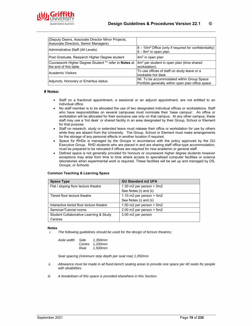
Space Guidelines GU has developed space guidelines to provide a method by which rational planning and management decisions can be made. The space allocations reflect the functions for which a space can be used. These space guidelines only reflect the quantity of space, not the quality. In each case, the functional requirements of the occupant have a bearing on the actual allocation of space. Unless noted otherwise on the SDFs or a Schedule of Usable Areas included in the Project Design Brief, the following space guidelines shall apply. Office Space
Occupant GU Standard m2 UFA#
Vice-Chancellor 20 - 28
Senior Executive Staff (DVC, PVC) 16 - 20
Dean, Director 14 - 16
Head of School 12 - 14
Academic Staff Levels C to E (Professor, Associate Professor, Principal or Snr. Lecturer, Principal or Senior Research Fellow, Lecturer Level B)
10 - 12
Academic Staff Level A & B 2 per 12m2 Office or 6 - 8m2 in open plan
Research Assistants, Research Fellows 1 & 2 2 per 12m2 Office or 6 - 8m2 in open plan
Administrative Senior Staff 10 - 12
Design Guidelines & Procedures Version 22.1 ©
September 2021 Page 19 of 230
(Deputy Deans, Associate Director Minor Projects, Associate Directors, Senior Managers)
Administrative Staff (All Levels) 8 – 10m2 Office (only if required for confidentiality)6 – 8m2 in open plan
Post Graduate, Research Higher Degree student 4m2 in open plan
Coursework Higher Degree Student ** refer to Notes at the end of this table
4m2 per student in open plan (time shared workstation)
Academic Visitors To use offices of staff on study leave or a bookable hot desk
Adjuncts, Honorary or Emeritus status Nil. To be accommodated within Group Space Portfolio generally within open plan office space
# Notes:
Staff on a fractional appointment, a sessional or an adjunct appointment, are not entitled to an
individual office. No staff member is to be allocated the use of two designated individual offices or workstations. Staff
who have responsibilities on several campuses must nominate their ‘base campus’. An office or workstation will be allocated for their exclusive use only on that campus. At any other campus, these staff may use a ‘hot desk’ or shared facility in an area designated by their Group, School or Element for that purpose.
Staff on research, study or extended leave must release their office or workstation for use by others while they are absent from the University. The Group, School or Element must make arrangements for the storage of any personal effects in another location if required.
Space for RHDs is managed by the Groups in accordance with the policy approved by the GU Executive Group. RHD students who are placed in and are sharing staff office-type accommodation, must be prepared to be relocated if offices are required for new academic or general staff.
Defined space is not generally provided for honours or coursework higher degree students however exceptions may arise from time to time where access to specialised computer facilities or science laboratories when experimental work is required. These facilities will be set up and managed by DS, Groups, or Schools
Common Teaching & Learning Space
Space Type GU Standard m2 UFA Flat / sloping floor lecture theatre 1.30 m2 per person + 5m2
See Notes (i) and (ii) Tiered floor lecture theatre 1.10 m2 per person + 5m2
See Notes (i) and (ii) Interactive tiered floor lecture theatre 1.50 m2 per person + 5m2 Seminar/Tutorial rooms 2.00 m2 per person + 5m2 Student Collaborative Learning & Study Centres
3.00 m2 per person
Notes i. The following guidelines should be used for the design of lecture theatres;
Aisle width Side 1,350mm
Centre 1,200mm Rear 1,500mm
Seat spacing (minimum step depth per seat row) 1,050mm
ii. Allowance must be made in all fixed-bench seating areas to provide one space per 40 seats for people
with disabilities.
iii. A breakdown of this space is provided elsewhere in this Section.
Design Guidelines & Procedures Version 22.1 ©
September 2021 Page 20 of 230
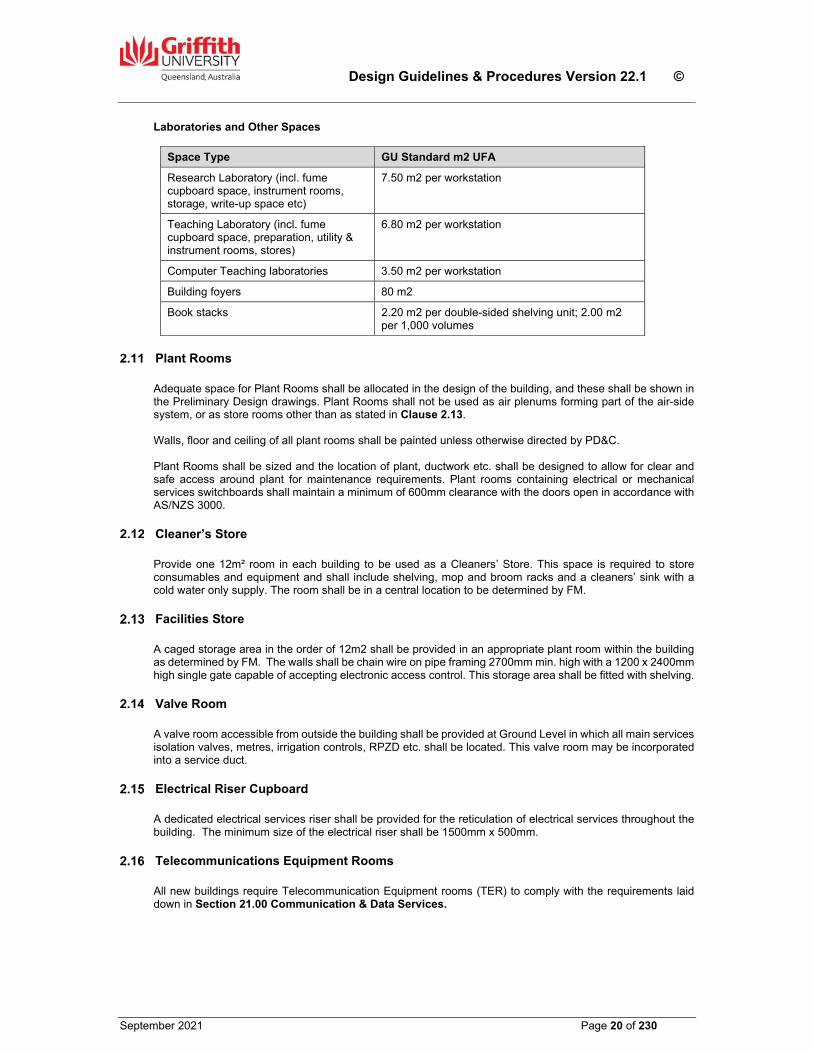
Laboratories and Other Spaces
Space Type GU Standard m2 UFA
Research Laboratory (incl. fume cupboard space, instrument rooms, storage, write-up space etc)
7.50 m2 per workstation
Teaching Laboratory (incl. fume cupboard space, preparation, utility & instrument rooms, stores)
6.80 m2 per workstation
Computer Teaching laboratories 3.50 m2 per workstation
Building foyers 80 m2
Book stacks 2.20 m2 per double-sided shelving unit; 2.00 m2 per 1,000 volumes
Plant Rooms Adequate space for Plant Rooms shall be allocated in the design of the building, and these shall be shown in the Preliminary Design drawings. Plant Rooms shall not be used as air plenums forming part of the air-side system, or as store rooms other than as stated in Clause 2.13. Walls, floor and ceiling of all plant rooms shall be painted unless otherwise directed by PD&C. Plant Rooms shall be sized and the location of plant, ductwork etc. shall be designed to allow for clear and safe access around plant for maintenance requirements. Plant rooms containing electrical or mechanical services switchboards shall maintain a minimum of 600mm clearance with the doors open in accordance with AS/NZS 3000.
Cleaner’s Store Provide one 12m² room in each building to be used as a Cleaners’ Store. This space is required to store consumables and equipment and shall include shelving, mop and broom racks and a cleaners’ sink with a cold water only supply. The room shall be in a central location to be determined by FM.
Facilities Store A caged storage area in the order of 12m2 shall be provided in an appropriate plant room within the building as determined by FM. The walls shall be chain wire on pipe framing 2700mm min. high with a 1200 x 2400mm high single gate capable of accepting electronic access control. This storage area shall be fitted with shelving.
Valve Room A valve room accessible from outside the building shall be provided at Ground Level in which all main services isolation valves, metres, irrigation controls, RPZD etc. shall be located. This valve room may be incorporated into a service duct.
Electrical Riser Cupboard A dedicated electrical services riser shall be provided for the reticulation of electrical services throughout the building. The minimum size of the electrical riser shall be 1500mm x 500mm.
Telecommunications Equipment Rooms All new buildings require Telecommunication Equipment rooms (TER) to comply with the requirements laid down in Section 21.00 Communication & Data Services.
Design Guidelines & Procedures Version 22.1 ©
September 2021 Page 21 of 230
Waste Collection and Gas Bottle Storage Each building shall be provided with a combined general and recyclable waste collection station at each level. The stations shall be easily accessible to the occupants and preferably located in a recess to a corridor wall. The number of general and recyclable waste bins at each station shall reflect the volume and type of waste generated by the activities on that level. Where the provision of industrial waste containers and wheelie bin storage is associated with a project, particular care is to be taken in the design of these areas to ensure unrestricted access for waste collection vehicles while at the same time providing suitable visual screening from the campus generally. Adequate provision shall be made for the secure and ventilated storage of gas bottles whether located internally or externally of a building. Refer to Subclause 18.04.02 in Section 18.0 Mechanical Services.
Corridors Wherever possible, corridors shall terminate at the external wall of the building to enable natural light to be admitted into the corridor space through windows in the building facade. The design of corridors, foyer spaces and the like shall ensure that there are no unnecessary recesses, alcoves, dead areas and the like which could be used for depositing rubbish or as unapproved storage spaces by building users.
Links to Adjacent Buildings
The design of new buildings shall address linkages to adjacent buildings by pathways, covered links or bridges, depending on the building function, location of the building relevant to those adjacent, the topography of the site or other considerations, which will be outlined in the Strategic or Technical Briefs. The design of covered links or bridges should utilise open and lightweight structural principles to minimise their visual impact.
Vending Machines Consideration shall be given in the design of public external spaces adjoining 24x7 accessible facilities, collaborative learning centres, commercial or other buildings generally on the campuses, for the installation of vending machines to be provided by others. The vending machines should be housed in an alcove or isolated structure designed to accommodate the varying machine sizes, and to minimise their visual impact. Allowance should be made for lighting, power, water outlets and drainage to sewer. Vending machines shall be located in areas approved by PD&C away from building entries, and not adjacent to foyers of Lecture Theatres, teaching type buildings or library facilities.
End of Trip Facilities Each new building project shall consider the requirements of the Queensland Development Code with respect to the provision of ‘End of Trip’ (EoT) facilities. Rather than provide an EoT facility in each building, GU has adopted the principle of providing a facility which will service a number of buildings in close proximity. This shared facility may be ‘stand-alone’ or be incorporated into a building. A number of these shared facilities currently exist on GU campuses, and the PD&C Senior Architect shall be consulted to establish if an existing facility is capable of servicing a new project, or whether a new EoT facility shall be provided to service the new building plus other existing and future buildings.
Toilets Toilets shall be provided to meet the expected occupancy of the building after consultation with the users and the Building Surveyor. All toilets, particularly in student areas, shall have ‘maze’ entries except for PWD toilets or in situations where noise may impact on adjacent spaces e.g. open plan offices, reception and waiting spaces. Refer to Clause 2.05 of this Section for particular issues to be addressed in the design of toilets for people with disabilities. All new buildings shall have gender neutral toilets provided. The extent of these shall be determined following consultation with GU.
Design Guidelines & Procedures Version 22.1 ©
September 2021 Page 22 of 230
Shower & Baby Change Facilities Provide in each building at Ground Floor level, a shower in the toilet for people with disabilities in accordance with AS1428 Part 1. Also provide a folding baby change table fixed on the wall in the same room. If the PWD at Ground Floor level is to be fitted with an electrically operated swing door opening system as per Clause 2.05 of this Section, then the shower and baby change table shall be relocated to a PWD toilet on another level in the building.
Parenting Room Each new building project shall consider the requirement for providing a Parenting Room to allow staff and students attending the campus with babies and small children to have purpose designed facilities and privacy for feeding, nappy changing and other infant care functions. Rather than provide a Parenting facility in each building, GU has adopted the principle of providing a facility which will service a number of buildings in close proximity. The PD&C Senior Architect will determine if a Parenting Room is to be provided in the project. The room shall comprise the following;
two feeding/milk expressing cubicles of a size to accommodate an armchair and small ‘coffee’ table; hinged door panels with indicator bolt; a double GPO to each cubicle.
a fixed two station change bench with profiled top and central flush s.s. sink bowl; a flat surface at each bench end for carrier bag placement; a hopper style waste bin under each station for soiled nappies,
a food/bottle preparation bench cupboard with a flush s.s. sink bowl, two electric bottle and food warming appliances (Phillips ADVENT 355 or equal) hard wired to a dual
cable entry flush wall plate with adjacent power isolating switch, fridge for milk and food storage wall mounted hand wash basin with laminate faced splashback panel, mirror, towel dispenser, soap
dispenser, hot and cold water to sinks and basin with lever handle taps, adequate floor space to manoeuvre and park strollers/prams without blocking access to benches and
cubicles electronic access control to room.
Collaborative Learning & Study Centres Collaborative Learning & Study Centres shall be located at ground level with good visibility and direct access from the main pedestrian circulation pathways past the building. Access to the Centre must be available outside normal hours without compromising the security of the building, therefore it should have its own entry separate from the main building foyer and which is capable of closure should it be required. If a separate entry is not possible, then it should be located as close as possible to the building’s main entry to avoid students having to penetrate too deeply into the building to access the Centre. There shall be sufficient windows in the external walls to provide an adequate level of natural light and visibility to passing pedestrian traffic. The natural light levels provided should consider that large TV monitors will be present in some zones. The Centre shall contain a number of distinct activity components, which are generally to be screened from but not totally segregated from the other components by solid walls or doors. Careful consideration shall be given to the acoustics within the Centre such that noise from one component does not become a problem to those using other components. The number of each component type will depend on the size and location of the Centre. The activity components are as follows. Collaboration Zone (technology enabled) – a space where students can collaborate on the preparation and presentation of group projects and assignments. Each zone shall comprise fixed banquet seating in a ‘U’ form facing a wall on which large TV monitors are mounted to display individual project work for group discussion. The floor should be raised to facilitate data cable connections from the seating to the wall mounted monitors. There shall be ramped wheelchair access to the raised floor area. Collaboration Booth (technology free) - a space where students are able to collaborate in a casual manner without a need to display information to all members of the group simultaneously. Each booth shall have lounge style seating with high backs and small loose tables. These spaces can also be utilised for quiet study.
Design Guidelines & Procedures Version 22.1 ©
September 2021 Page 23 of 230
Team Study Booth – booths shall be capable of accommodating four (4) to six (6) students. The end wall shall be a solid wall with a mounting panel for a large TV monitor. Screens between booths should contain a minimum of 50% glass for visual surveillance and transmission of natural light. Individual Study Zone – this zone shall be located on the perimeter of the Centre and will comprise fixed computer wall benching to suit a minimum of twenty (20) desk top computers for casual use by students. The number of computers shall be determined by DS. Chill/Quiet Zone – a space for students to relax or socialise in a quiet space where group activity does not occur. Lounge - a centrally located open area with a mix of fixed and loose furniture where students can work individually or in pairs using their own personal devices, and where they can wait to gain access to a collaboration zone, a booth or a common use computer. Resource area – printing stations with control/pay unit and a lockable stationery store. Examples of typical Collaborative Learning & Study Centres are located on Level 0 of the Patience Thoms (N06) building at the Nathan campus, and on Level 2 of the Learning Commons (G11) building at the Gold Coast campus.
Lecture Theatres, Auditoria & Other Teaching Spaces The design of lecture theatres, auditoria and other teaching spaces shall incorporate the principles outlined in the current edition of the ‘AETM Audio Visual Design Guidelines for Tertiary Teaching Spaces’. The acoustic performance of lecture theatres and auditoria are fundamental to successful teaching and so special consideration shall be given to the design of these spaces with respect to acoustical performance. The requirements of Sections 6 & 7 of the AETM Design Guidelines shall apply. The front wall of the theatre is used for projection and must accommodate a main picture size not less than 4m wide unless approved otherwise by DS. The form of projection to be used in the space must be confirmed with DS. Lecture theatres with more than 250 seats may require a Projection Room/Bio Box. This must be confirmed with DS. The design of the seating layout in lecture theatres and auditoria shall be governed by the requirements of Section 4 of the AETM Design Guidelines. Refer to Sections 12, 13 & 14 of the AETM Design Guidelines for the technology requirements, including lighting, for large, medium and small teaching spaces and for meeting rooms.
Video Conferencing Rooms Video Conferencing rooms shall ideally be spaces without windows to allow optimum light control through artificial means. Where windows exist and it is not practical to remove or block them out, then the video screen shall be located as far away as possible from the windows (e.g. opposite wall), and blinds shall be provided to reduce the level of natural light in the room to a level acceptable to ESA. The room requires 24 x 7 access control for security of equipment.
Laboratories A Laboratory is classified as any building or part of a building used or intended to be used for scientific or technical work which may be hazardous, including research, quality control, testing, teaching or analysis. Such work may involve the use of chemicals including dangerous goods, pathogens and harmful radiation, quarantine materials, or processes including electrical or mechanical work which could also be hazardous. The laboratory includes such support areas as instrument and preparation areas, laboratory stores and any offices ancillary to the laboratory.
Design Guidelines & Procedures Version 22.1 ©
September 2021 Page 24 of 230
All laboratories must comply with the Building Code of Australia, AS 2982, AS 2243 Parts 1-10 inclusive, AS 1940, AS 4332, AS 2430, AS/NZ 2982.1 and referenced and related documents including the Workplace Health and Safety Act and regulations. The design of all laboratories shall be reviewed with Group technical managers and GU WH&S officers to ensure compliance with all standards and regulations. When preparing designs for laboratories, the consultants must confirm with the Users the likely use and storage of flammable liquids within the space, to ensure that electrical exclusion zones can be determined and that the quantities of flammable liquids to be stored do not exceed to maximum allowable by the relevant Standard. In the determining the exclusion zones required, GU’s preference is that these are established in accordance with the Australian Standard, rather than by a ‘risk assessment’ methodology. Consultants are required to present adequate documentation to the Users to acquaint them fully with the impact on the laboratory design from storing flammable liquids in the space. In the event that this impact severely compromises the functional operation of the laboratory, then alternative storage locations should be investigated, or approval may be sought from CLF to undertake a risk assessment to minimise the zones required. Any such assessment shall only be undertaken by firms or persons approved by PD&C. For Physical Containment (PC) spaces, the consultants shall prepare documentation which clearly identifies the extent and boundaries of the space. Penetrations through the boundaries (floor, wall or ceiling) of the PC space shall be specifically detailed to prevent the entry of vermin. The ceiling space or roof void above the space shall be sealed to the underside of slab or roof decking to minimise air leakage.
Building Areas & Definitions Building Areas for GU projects shall be measured in accordance with principles established by the Tertiary Education Facilities Management Association (TEFMA), which are set out as follows. All areas are measured in square metres. Fully Enclosed Covered Area (FECA) – is the sum of all fully enclosed covered areas at all building levels, including basements (except unexcavated portions), floored roof spaces and attics, garages, penthouses, enclosed porches and attached enclosed covered ways alongside buildings, equipment rooms, lift shafts, vertical ducts, staircases and any other fully enclosed spaces and useable areas of the building, computed by measuring from the normal inside face of external walls but ignoring any projections such as plinths, columns, piers and the like which project from the normal inside face of exterior walls. It shall not include open courts, light wells, connecting or isolated covered ways and net open areas of upper portions of rooms, lobbies, halls, interstitial spaces and the like, which extend through the storey being computed. Note: Atriums and light wells are only measured at the base level. Do not include the area of the non-existent floor slab at upper levels. Unenclosed Covered Area (UCA) – is the sum of all unenclosed covered areas at all building floor levels including roofed balconies, open verandas, porches and porticos, attached open covered ways alongside the building(s), useable space under the building(s), unenclosed access galleries (including ground floor) and any other trafficable covered areas of the building which are not totally enclosed by full height walls. The UCA is computed by measuring from the inside face of any enclosing walls, balustrades or supports, but excludes connecting or isolated covered ways and eaves, overhangs, sun shading, or awnings unless they relate to clearly defined trafficable covered areas. Gross Floor Area (GFA) - is the sum of the Fully Enclosed Covered Area (FECA) and the Unenclosed Covered Area (UCA). GFA = FECA+UCA (m2) Usable floor Area (UFA) – is the sum of the floor areas measured at floor level from the general inside face of the walls of all spaces related to the primary function of the building. This will normally be computed by calculating the FECA and deducting common use areas, service areas and non-habitable areas. If an area which may be deemed as ‘common use’ or ‘service area’ e.g. entry foyer, tea room, or store room, is included in the briefed Schedule of Areas, then those areas shall be included in the calculation of UFA. Foyers to large Lecture Theatres should be treated as UFA.
Design Guidelines & Procedures Version 22.1 ©
September 2021 Page 25 of 230
In some cases, the UFA may include some external covered areas which relate to the primary function of the building but are not part of the FECA e.g. covered play area for a Child Care Centre, open roofed civil engineering hydraulics-modelling laboratory. ‘Common use area’ includes corridors which are defined by partitions, but do not include passages and secondary circulation areas associated with ’open plan’ spaces. ‘Non-habitable area’ is the area occupied by internal columns and other internal supports, internal walls and permanent partitions, service ducts and the like.
Building Efficiency Building efficiency for GU projects is to be computed by dividing the Usable Floor Area (UFA) by the Gross Floor Area (GFA) and expressing the result as a percentage. The efficiency required by building type shall not be less than the following;
Science – 60% Humanities – 65% Administration – 65% Library – 70 to 75% Arts – 70% Learning Centre – 70%
Acoustic Requirements for Internal Spaces Regulatory Requirements – Authority and code requirements relevant to acoustic considerations with respect to GU developments include:
EPA Environmental Protection Policy (Noise) 1997 EPA Environmental Protection Amendment Regulation No 2 1999 BCC Planning Policies Current Australian Standards including AS 1035, AS 1045, AS 1296, AS 2021, AS2822, AS 2436,
AS 3671, AS/NZS 2107 WH&S Act & relevant regulations
Scope of Acoustic Considerations – In the design of new buildings, or in the refurbishment of existing facilities, acoustic considerations may include:
External noise intrusion Noise generated within the building due to building services Noise emissions from the building as they affect adjoining buildings or residents Noise interactions between spaces and consequent privacy considerations Acoustic quality of spaces such as speech intelligibility Special acoustic requirements such as sound or video recording.
External Noise Intrusion – Typical noise from external sources to be dealt with in the design include:
Traffic noise (road, rail and/or aircraft sources) Equipment associated with adjacent buildings and industrial activities
These types of intrusive noise can be classified as either:
Steady or pseudo-steady Transient (e.g. aircraft fly over).
These types of noise can be quantified as:
Steady: Equivalent continuous measurement: LAeq Transient: Noise level exceeded for 1% of the time: LA01 Criteria apply over any one (1) hour period during applicable hours (for University activities: 8am to
10pm).
Design Guidelines & Procedures Version 22.1 ©
September 2021 Page 26 of 230
Limits of acceptable noise intrusion are listed below in Table 2.1.
Table 2.1
Room Type LAeq LA01
Faculty Offices and all other individual offices 37dBA 45dBA
Administrative/clerical office (open space), post graduate student areas 37dBA 50dBA
Counselling Office 37dBA 45dBA
Teaching Room 37dBA 45dBA
Lecture Theatre 32dBA 40dBA
Library 40dBA 50dBA
Video-conferencing Room 32dBA 40dBA
Corridors, Lobbies 45dBA 55dBA
Noise Emissions – Noise emissions can arise from building services or the functional activities of the space. This category includes noise generated by activity associated with the functioning of the space (e.g. delivery vehicles to a loading dock). Noises of this type may impact on buildings on or off campus. The acoustic characteristics of potentially-affected adjoining buildings will need to be taken into account to determine acceptable noise emissions from the proposed new building and its associated noise source(s). Criteria for campus buildings: refer Table 2.1 Criteria for adjoining (off-site) buildings and facilities: refer applicable statutory requirements. Building Services – These noise sources include fans, motors and pumps etc. The noise can be transferred to other spaces by two mechanisms:
Air-borne noise transmission Structure-borne noise transmission.
Both mechanisms of transmission must be considered in the design, by the provision of appropriate sound insulation and structural isolation. Noise from building services shall not exceed the following values:
Table 2.2
Room Type LAeq Adj
Faculty Offices and all other individual and shared staff offices 37dBA
Administrative/clerical office (open space), post graduate student areas 37dBA
Counselling Office 37dBA
Teaching Room 37dBA
Lecture Theatre 32dBA
Library 40dBA
Video-conferencing Room 32dBA
Corridors Lobbies 45dBA
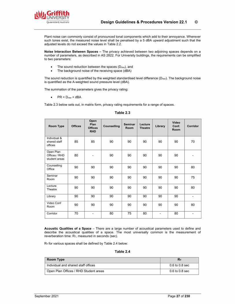
Design Guidelines & Procedures Version 22.1 ©
September 2021 Page 27 of 230
Plant noise can commonly consist of pronounced tonal components which add to their annoyance. Wherever such tones exist, the measured noise level shall be penalised by a 5 dBA upward adjustment such that the adjusted levels do not exceed the values in Table 2.2. Noise Interaction Between Spaces – The privacy achieved between two adjoining spaces depends on a number of parameters, as described in AS 2822. For University buildings, the requirements can be simplified to two parameters:
The sound reduction between the spaces (Dntw), and The background noise of the receiving space (dBA)
The sound reduction is quantified by the weighted standardised level difference (Dntw). The background noise is quantified as the A-weighted sound pressure level (dBA). The summation of the parameters gives the privacy rating:
PR = Dntw + dBA Table 2.3 below sets out, in matrix form, privacy rating requirements for a range of spaces.
Table 2.3
Room Type Offices
Open Plan
Offices RHD
Counselling Seminar
Room Lecture Theatre
Library Video Conf. Room
Corridor
Individual & shared staff offices
85 85 90 90 90 90 90 70
Open Plan Offices / RHD student areas
80 - 90 90 90 90 90 -
Counselling Office
90 90 90 90 90 90 90 80
Seminar Room
90 90 90 90 90 90 90 75
Lecture Theatre
90 90 90 90 90 90 90 80
Library 90 90 90 90 90 90 90 -
Video Conf Room
90 90 90 90 90 90 90 80
Corridor 70 - 80 75 80 - 80 -
Acoustic Qualities of a Space – There are a large number of acoustical parameters used to define and describe the acoustical qualities of a space. The most universally common is the measurement of reverberation time: RT, measured in seconds (sec). RT for various spaces shall be defined by Table 2.4 below:
Table 2.4
Room Type RT
Individual and shared staff offices 0.6 to 0.8 sec
Open Plan Offices / RHD Student areas 0.6 to 0.8 sec
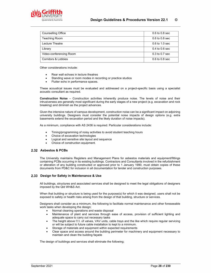
Design Guidelines & Procedures Version 22.1 ©
September 2021 Page 28 of 230
Counselling Office 0.6 to 0.8 sec
Teaching Room 0.6 to 0.8 sec
Lecture Theatre 0.6 to 1.0 sec
Library 0.4 to 0.6 sec
Video-conferencing Room 0.3 to 0.7 sec
Corridors & Lobbies 0.6 to 0.8 sec
Other considerations include:
Rear wall echoes in lecture theatres Standing wave or room modes in recording or practice studios Flutter echo in performance spaces.
These acoustical issues must be evaluated and addressed on a project-specific basis using a specialist acoustic consultant as required. Construction Noise – Construction activities inherently produce noise. The levels of noise and their intrusiveness are generally most significant during the early stages of a new project (e.g. excavation and rock breaking) and diminish as the project advances. Given the intensive nature of campus development, construction noise can be a significant impact on adjoining university buildings. Designers must consider the potential noise impacts of design options (e.g. extra basements extend the excavation period and the likely duration of noise impacts). As a minimum, compliance with AS 2436 is required. Particular considerations include:
Timing/programming of noisy activities to avoid student teaching hours Choice of excavation technologies Logical and sensitive site layout and sequence Choice of construction equipment.
Asbestos & PCBs The University maintains Registers and Management Plans for asbestos materials and equipment/fittings containing PCBs occurring in its existing buildings. Contractors and Consultants involved in the refurbishment or alteration of any building constructed or approved prior to 1 January 1990, must obtain copies of these documents from PD&C for inclusion in all documentation for tender and construction purposes.
Design for Safety in Maintenance & Use All buildings, structures and associated services shall be designed to meet the legal obligations of designers imposed by the Qld WH&S Act. When that building or structure is being used for the purpose(s) for which it was designed, users shall not be exposed to safety or health risks arising from the design of that building, structure or services. Designers shall consider as a minimum, the following to facilitate normal maintenance and other foreseeable work tasks when developing the design;
Normal cleaning operations and waste disposal Maintenance of plant and services through ease of access, provision of sufficient lighting and
adequate space to carry out necessary tasks The height above f.f.l. of valves, VAV units, cable trays and the like which require regular servicing
or will be subject to future cable installation to kept to a minimum. Storage of materials and equipment within expected requirements Clear space and access around the building perimeter for machinery and equipment necessary to
maintain and clean the building façade The design of buildings and services shall eliminate the following;
Design Guidelines & Procedures Version 22.1 ©
September 2021 Page 29 of 230
Unnecessary need to access hazardous areas such as roof surfaces or confined spaces for maintaining plant or services
Generation of mould and other indoor air quality issues affecting the health of users Electrical exclusion zones and disabled access clearances shall be marked and identified on the architectural floor plans. A written report outlining the measures taken in the design to address the foregoing shall be submitted to PD&C for review prior to the issue of any tender documents or TPS submission by the lead design consultant or Contractor.
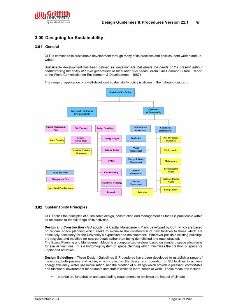
Design Guidelines & Procedures Version 22.1 ©
September 2021 Page 30 of 230
3.00 Designing for Sustainability
General
CLF is committed to sustainable development through many of its practices and policies, both written and un-written. Sustainable development has been defined as ‘development that meets the needs of the present without compromising the ability of future generations to meet their own needs’. (from ‘Our Common Future’, Report to the World Commission on Environment & Development – 1987) The range of application of a well-developed sustainability policy is shown in the following diagram.
Sustainability Principles CLF applies the principles of sustainable design, construction and management as far as is practicable within its resources to the full range of its activities. Design and Construction - GU adopts the Capital Management Plans developed by CLF, which are based on rational space planning which seeks to minimise the construction of new facilities to those which are absolutely necessary for the University’s expansion and development. Wherever possible existing buildings are recycled and modified for new purposes rather than being demolished and reconstructed. The Space Planning and Management Model is a computerized system, based on standard space allocations for similar functions. It is a bottom-up system of space planning which minimises the creation of space for unplanned activities. Design Guidelines - These Design Guidelines & Procedures have been developed to establish a range of measures, both passive and active, which impact on the design and operation of GU facilities to achieve energy efficiency, water use minimisation, and the creation of buildings which provide a pleasant, comfortable and functional environment for students and staff in which to learn, teach or work. These measures include:
orientation, fenestration and sunshading requirements to minimise the impact of climate
Sustainability Policy
Design and Construction for Sustainability
Capital Management Plans
Space Planning
Design Guidelines
Building Rating
Energy Targets
CPTED
Materials, Finishes,Orientation
Campus Master Plans
Site Planning EnvironmentalManagement
Purchasing
Waste Management
Grounds Management
Energy & WaterManagement
AsbestosManagement
Education
ContinuousImprovement
Post OccupancyEvaluation
Maintenance
Facilty Audits
Environmental Audits
Health and Safety Audits
Energy Audits
Operations for Sustainability
Commissioning
Research
Greenhouse Challenge
Policy Statement
Management Plan
Operational Plan/Document
Design Guidelines & Procedures Version 22.1 ©
September 2021 Page 31 of 230
balancing excessive solar heat gain and collecting natural lighting into the building. insulation to roofs and walls use of central energy plants to minimise energy usage for air conditioning use of central control and monitoring systems to optimize building operations for minimum wastage specification of energy-efficient building services water conservation requirements for toilets, showers and irrigation systems selection of materials which have low or no VOC emissions and which can be recycled the adoption of ‘Crime Prevention through Environmental Design’ (CPTED) as a method of using good
design and low technology to provide good security the specification of indigenous species for replanting of vegetation on sites so as to minimise the need
for excessive artificial irrigation following establishment of the plants requirements for environmental site management which regulates waste management, erosion control,
pollution control on construction sites. Site Planning - GU engages in periodic site planning reviews in order to minimise waste through unforeseen and unplanned development. As part of the site planning process, particular attention is given to environmental issues with the intent of minimising the impact of ongoing development on the natural environment. Master Plans have been developed for each campus and are used to guide development over time. These Master Plans are reviewed whenever there is a perceived major change in conditions, both internal and external, affecting the University. The results of these reviews are demonstrated by the following:
compact development of the Nathan, Mt Gravatt and Gold Coast campuses maximises the retention of the forest environment and at the same time reduces the impact and cost of reticulating site services such as electricity, water, sewerage and communications systems
development of the South Bank campus recycles previous development sites thereby reducing the impact on the environment through greenfield development
development of the Logan campus recycles a previously cleared site while at the same time reintroduces vegetation to areas cleared for farming. The development has also identified some small areas of remanent vegetation which is worthy of protection
site planning for the Southern Precinct of the Gold Coast campus includes a commitment to environmentally sustainable development and acknowledgement of Native Title issues.
Energy Management - GU’s Energy Management Policy actively seeks to eliminate waste and to improve the efficiency of energy use, so that University funds may be directed to the primary function of teaching and research consistent with the development of the University. The methods which will be adopted to achieve these objectives will be determined within the financial limitations of the University and with regard to the likely savings to be achieved. Water Management – GU seeks design principles and initiatives in its buildings which embrace current technology and practices to minimise or avoid the use of water. Such principles include;
the installation of tanks to harvest rainwater for reuse in the building water efficient sanitary fixtures and tapware waterless urinals eliminate the need for landscape irrigation systems through careful plant selection
Waste Reduction - GU requires that the amount of construction waste going to landfill is minimised, and resources are conserved through avoidance, reuse and recycling. These principles are to be incorporated into the design of its buildings through careful material selection and dimensioning to utilise standard material sizes in building fabric and fittings. Material Selection - GU is continually evaluating material alternatives to optimise their total life cycle performance. This includes material property alternatives complying with the following;
a high recycled content locally/regionally produced made from rapidly renewable agricultural byproducts (as opposed to petroleum based products) ability to be reused, recycled, or that are biodegradable
Design Guidelines & Procedures Version 22.1 ©
September 2021 Page 32 of 230
maximum durability based on anticipated life of interior construction, equipment, finishes and furnishings.
Energy Simulation (mandatory requirement) Computerised building energy simulations shall be conducted by the Consultants on any building having a designed total gross floor area of 1,000m ² or more. The requirements of Section J of the BCA shall be the minimum benchmark for energy efficiency. The simulation shall dynamically model the building envelope thermal effects, and the operation of major energy consuming equipment such as HVAC, lighting etc. Results of the simulation shall provide information about the performance, capital and running cost implications as well as energy use profiles of at least two design options. The simulation shall be provided to CLF at the early design planning stage with a view to selecting the preferred option before finalisation of the developed sketch plans and cost estimates. The design team shall liaise with the CLF mechanical and electrical engineers regarding further reviews that may be required to confirm that the design of the building and services has achieved the energy consumption projections of the simulation.
Building Management System GU's buildings are controlled and managed through a Building Management System (BMS) on each campus. All available functions of the BMS are to be programmed into the various systems such as temperature reset, special days, load shed and optimum start/stop. Specific control and monitoring requirements are outlined in the following Sections of this document;
Section 17 Hydraulic Services Section 18 Mechanical Services Section 19 Fire Services Section 20 Electrical Services Section 23 Lifts
Sustainable Design Compliance Matrix All Head Consultants or Contractors are required to submit a completed ‘Sustainable Design Compliance Matrix’ as part of their Developed Design proposal or Total Project Sum Submission for new buildings or major refurbishment projects. The object of the Matrix is to demonstrate that designers have considered all the sustainability issues that impact on the project, and to nominate if their design addresses those issues or provide the reasons why they have not been adopted. A copy of the Matrix is contained in Section 32.00 Standard Forms.

Design Guidelines & Procedures Version 22.1 ©
September 2021 Page 33 of 230
4.00 Section deleted refer to RFT documents
Design Guidelines & Procedures Version 22.1 ©
September 2021 Page 34 of 230
5.00 Building Structure
Generally As a general principle, GU requires the design of its new buildings to incorporate flexibility for future changes in internal layout or use. This requirement should be reflected in the design of the building structure. GU does not seek to impose any structural design principles or methodologies on Consultants or Contractors, however it does require a structural design which combines both flexibility and economy.
Floor to Floor Heights Floor to floor heights should be kept to a minimum while at the same time allowing sufficient space in ceilings for services distribution to maintaining a minimum ceiling height of 2.70m. Floor to floor height should match adjacent buildings if appropriate. The projection screen size in large teaching spaces must be considered when determining the floor to floor heights in a building where such spaces are required.
Location of Columns Careful consideration must be given to the location of columns within the building. Columns located on the centre line of the building generally impose constraints on the layout of the floors, particularly those levels incorporating Academic Offices. As it is the general policy of GU to locate Academic Offices on the external wall of the building to provide maximum natural light to these spaces, and all offices are generally of equal size, this often results in a central corridor which must not be obstructed by columns. Columns within the body of a functional space should be avoided wherever possible. This applies in particular to Lecture Theatres and Seminar Rooms. Clear span slabs with no intermediate columns are desirable if budgetary constraints permit.
Slabs Floor slabs shall be designed for the most economical construction and flexibility of use with due consideration to long-term deflections and the need to provide for penetrations both initially and during the course of the building's life. All buildings shall be designed for floor loadings generally in accordance with AS 1170.
Library stack areas shall be designed for floor loadings of 6.0kN/m2 provided that stack height is limited to
2.3m. Provision shall be made for the installation of compactus shelving and other areas of special loading if specifically nominated by the Space Description Forms. The slab design shall provide for the need to core holes, now or at a later date, up to 200mm diameter adjacent to columns, or to provide penetrations up to 1200mm square in selected areas. All floors are to be finished within a maximum tolerance of + 3mm in a 3000mm straight edge. Thermal resistance (R-values) of the floor is to be >1.0m2 K/W. As stated in the previous Clause, clear spanning slabs without intermediate support are desirable. In designing such slabs, consideration should be given to the depth of beams to accommodate ductwork and other services suspended below the slab without unnecessarily increasing the floor to floor height. If post tensioned slabs are installed, the location of all tendons must be clearly and permanently marked on the underside of the slab to ensure that any future core holes or penetrations cut in the slab do not intersect any stressing cables. In locating the permanent markers, consideration must be given to the possible concealment of the markings by ductwork, cable trays and the like.
Design Guidelines & Procedures Version 22.1 ©
September 2021 Page 35 of 230
Construction and expansion joints shall be positioned to minimise cracking and to avoid unsightly gaps in floors and wall as a result of long term movement of the structure. All internal floor slabs on ground shall be placed on moisture barrier equivalent to 300 micron thick ‘Fortecon’ polythene membrane, turned up at the perimeter and with all joints sealed. Any requirement for in-slab floor boxes and conduits for cable access to lecterns or other equipment in teaching spaces, must be established with DS early in the design process prior to slab thicknesses being finalised.
Structural Walls Concrete or masonry walls should be kept to minimum to ensure flexibility for future internal modifications or alterations. Masonry walls should be limited to lift shafts, fire stairs and plant rooms wherever possible. Masonry walls required for bracing purposes should be carefully located so as not to impact severely on flexibility.
Tanking Floors, walls and lift pits shall be fully tanked where below grade or subject to hydrostatic pressure.
Termite Control Protection from subterranean termites shall be provided to all new buildings. All workmanship and materials shall conform to the requirements of AS 3660 Part 1: New Building Work. All tree stumps and root boles which have been exposed during excavation, together with any dead logs and other timber debris, shall be removed from the building site. Stainless steel mesh barriers which comply with the requirements of Section 6 of AS 3660.1, are to be used to provide protection against termite entry. Stainless steel mesh barriers shall also be used between the slab edge and the wall, and across wall cavities in masonry wall structures. The use of chemically impregnated barrier systems shall not be used without the specific approval of the Superintendent. Termite caps or strip shielding complying with the requirements of Section 5 of AS 3660.1 shall be installed on all foundation walls, piers, stumps and other substructures in such a manner that the structure is isolated by the barriers from the substructure. The Contractor shall provide the Superintendent with a Certificate of Installation in accordance with AS 3660.1 Appendix A, from the installer of the termite management system.
5.08 Sealing Penetrations Fire rated sealing of penetrations through floors and walls shall be done in accordance with the requirements of the BCA and AS3000. Fire rated floor slabs and walls must have their fire-stopping capabilities restored after the installation of cabling, conduits, cable trays, ducting or pipework which pass through any penetrations. ‘Hilti Firestop’ foam, blocks, logs, plugs and mastic, or tested equal, are the preferred materials for the sealing of penetrations through fire rated floors and walls, installed strictly in accordance with the manufacturers printed instructions.
Design Guidelines & Procedures Version 22.1 ©
September 2021 Page 36 of 230
6.00 Staircases & Ramps All the requirements of this Section are Mandatory.
Generally Internal and external stairs and ramps shall comply in all respects with the requirements of the BCA and AS 1428 Part 1: New Buildings. Ramps shall be provided externally as required to provide access to buildings for people with disabilities. The use of ramps internally as a means of interconnecting floors is not an acceptable alternative to providing a lift. GU will not accept designs which combine maximum height risers with minimum width treads. Treads widths and riser heights shall generally comply with the requirements of AS 1428.2, with goings a minimum of 280mm wide.
Internal Stairs There shall be a general circulation stair to access to all levels of the building to minimise the use of lifts. This circulation stair may be a fire isolated stair provided all access doors are controlled with magnetic hold open devices connected to the fire alarm system. The following points are to be considered in the design and placement of circulation stairs:
Placement of stairs to maximise their visibility and use; Finishes to stair treads, risers and landings shall be ceramic tiles and walls shall be rendered and
painted with matching tile skirting; Comply with the requirements of AS 1428.2; Design of stairs to be social spaces where conversations can occur; Design of stairs to act, where appropriate as natural ventilation shafts; Stairs shall be provided with natural light if possible. Ensure fire services (fire hydrants and test drains) rising through stairwell do not encroach on
minimum stairwell widths. Fire isolated stairs shall be provided to satisfy the requirements of the BCA and AS 1428.2. These stairs may be fully enclosed within the building envelope, or may be open framed stairs external to the building façade.
External Stairs and Ramps
Ramps for disabled access to buildings shall comply with the requirements of AS 1428.1. The structural design of stair flights and ramps shall be to suit the actual ground conditions encountered.
Handrails Internal general access stairs, including fire isolated stairs for general access, shall have stainless steel handrails to both sides. Where the general access stairs are in an open well with exposed strings to flights, then a balustrade incorporating glass, perforated metal or other approved solid panels is desirable. Handrails and balustrades to fire isolated stairs which are not general access stairs, may be galvanised steel.
Finishes General use access stairs shall have a tiled finish to treads, risers and landings. Tiles to stairs shall be non-slip to suit the application with tread, riser and nosing tile of a contrasting colour and matching grout. Tiled stair landings and walls adjoining stairs shall have a matching skirting tile ½ tile height or minimum 100mm high.
Refer to Section 13.00 Floor Finishes, for details of the physical requirements of the tiles.
Design Guidelines & Procedures Version 22.1 ©
September 2021 Page 37 of 230
Fire isolated stairs, which are not general access stairs, shall have an integral non-slip finish to treads and landings, with a ‘Yellow’ painted nosing on both tread and landing edges. Where carpet finishes are approved for internal non fire isolated stairs, tread nosings shall be aluminium with adhesive fixed contrasting coloured inserts. All stair nosings shall be non-skid of dimensions to comply with AS 1428.2. Consideration should be given to the use of ‘self illuminating’ nosings such as ‘Ecoglo’, where step edge contrast is required, or would be enhanced, in low light conditions.
Tactile Ground Surface Indicators (TGSIs) Provide warning type TGSIs in accordance with the National Construction Code, Australian Standards AS1428.0 & 1428.4.1.
Directional type TGSIs shall be used where dictated by the needs of the specific project. CLF will advise when these indicators are appropriate based on advice from the University’s Access Consultant. TGSIs shall be selected to suit the particular application taking into account the substrate, appearance, consistency with surrounds, pedestrian/vehicular traffic, standards and code requirements. The type of TGSI to be used shall be selected from the following list of approved materials, and the selection made must be must be confirmed with the Superintendent before specifying or installing.
TGSI Material Manufacturer and/or SupplierCork / rubber composite pads
Safety floor Australia Pty Ltd; Comcork (see note below)
Rubber pads CTA Australia; PolyPad Ceramic tiles Australian Building Ceramics; Granito; CTA Australia; Cobble Tac Granite/Basalt tiles J.H. Wagner & Sons Concrete paving units Stone Directions; Urban StoneIndividual Stainless Steel Studs
Latham Australia; TI Series; CTA Australia; Sure Steel (see note below)
Note: The use of individual stainless steel stud indicators is not permitted except with the written approval of the Superintendent following the receipt of evidence as to the reasons why no other type of TGSI is appropriate or practical. Surface fixed pad type TGSIs will also not be permitted except where other nominated types are not appropriate or practical. TGSI tiles and pads shall be installed flush with the surrounding surfaces. The following combination of surface finishes and TGSIs are acceptable;
Internally - New Buildings
Floor finish TGSI material Carpet tiles Cork/rubber composite pads or Rubber pads Resilient Cork/rubber composite pads or Rubber pads Ceramic tiles Ceramic tilesStone paving Granite/basalt tilesIn situ concrete (no applied finish)
Ceramic tiles
Internally – Existing buildings
Floor finish TGSI materialCarpet tiles Cork/rubber composite pads or Rubber pads Resilient Cork/rubber composite pads or Rubber pads Ceramic/Quarry tiles Ceramic tiles
Design Guidelines & Procedures Version 22.1 ©
September 2021 Page 38 of 230
Externally – New stairs & ramps
Material/finish TGSI materialIn situ concrete (broomed or exposed aggregate finish)
Concrete paving units; Granite/basalt tiles
Stone paving Granite/basalt tilesCeramic tiles Ceramic tiles
Externally – Existing stairs & ramps
Material/finish TGSI material In situ concrete (broomed or exposed aggregate finish)
Concrete paving units; Granite/basalt tiles
Concrete paving units Concrete paving units; Granite/basalt tiles Ceramic/quarry tiles Ceramic tiles
Design Guidelines & Procedures Version 22.1 ©
September 2021 Page 39 of 230
7.00 Roofs All the requirements of this Section are Mandatory.
Roofs Generally All GU buildings shall have pitched roofs. The minimum pitch shall not be less than the roofing manufacturer’s recommendations for the particular materials adopted, however the roof pitch must never be less than five degrees (5o). Membrane roofs will not be acceptable except in special circumstances and only with the approval of the Associate Director, Minor Projects (PD&C) CLF. All plumbing vent pipes, other pipework, mechanical fans, cowls and the like located on or projecting above the roof shall be finished to match the roof colour. All metal framing exposed above the roof shall be hot dip galvanised after fabrication and be left unpainted. Roof design shall minimise the number of penetrations through the decking or membrane.
Roof Deck Materials Roofs shall generally be metal pan roof decking, manufactured from G550 hi-tensile colour coated (Colorbond) steel in accordance with AS 1397 and AS 2728-Category 3, with a thickness of 0.48mm BMT. The deck profile shall be equivalent to Stramit ‘Speed Deck Ultra’ and fixed on concealed clips in accordance with the manufacturer's printed instructions. All sealants, fixings and accessories shall match the colour of the roof. Ends of sheets must be turned up at ridges, penetrations and abutments, and turned down into gutters using specialist tools. The colour of the roof sheeting must be approved by CLF. If vertical linings are required where not exposed to view, they shall be in colour matched profiled steel wall sheeting with a thickness of 0.42mm BMT, equivalent to Stramit ‘K–Panel’.
Flashings and Cappings Roof flashings, cappings and trims shall be designed to minimise the use of sealants, and shall be fabricated and installed in accordance with the roof deck manufacturer's recommendations. Flashings, cappings etc. associated with the roofing shall be fabricated from Colorbond steel of the same thickness and colour as the roof sheeting. All fixing types are to be as recommended by the roof deck manufacturer and colour matched to the flashing. Where the ends of the roof sheeting are clearly visible above the eaves gutter, install a colour matched steel angle trim with the vertical leg positioned downwards and the other leg fixed to the top of the rib, with sufficient space between the vertical leg and the end of the decking pans to allow water run-off. Flashings to penetrations for roof access hatches, skylights, exhaust vents and the like shall incorporate a soaker flashing which shall extend to the roof ridge whenever possible. Flashings to all roof penetrations shall be designed to minimise the collection of leaves and debris. All box gutters shall have over flashings fitted under the end of the roof decking to the trimming purlin. ‘Decktite’ flashings are acceptable for circular penetrations, only where they are installed in a manner which does not impede roof drainage or allow ponding, and strictly in accordance with the manufacturers printed instructions. Where possible combine vents under roof line to minimise penetrations. Ensure vent penetrations occur as close as possible to the ridge line. Where flashings abut walls, a double ‘K’ flashing is required. Refer GU Standard Detail Drawing No GSD-107.
Design Guidelines & Procedures Version 22.1 ©
September 2021 Page 40 of 230
On some campuses, ‘Decktite’ flashings and sealants are subject to damage and removal by birds. Where this is a problem, a Colorbond steel shroud shall be installed to protect the ‘Decktite’ flashing, and exposed sealants should be protected by Colorbond metal trims. The PD&C Project Manager should be consulted as to the likely requirement for these measures.
Roof Insulation To the whole of the roof area, provide an R3 insulation blanket with foil faced backing laid over galvanised wire safety mesh fixed on top of the purlins.
Gutters Generally – Gutters for the harvesting of rainwater for reuse in toilet flushing or landscape irrigation, shall be installed on all buildings unless otherwise advised by CLF. If rainwater is not to be harvested, then gutters should be avoided wherever possible, and the rainwater should be allowed to discharge directly to the ground, clear of the building façade and pedestrian pathways etc where it can be collected in gravel filled trenches with agricultural drains for discharge into the stormwater system. Box gutters shall not be installed unless there is no other viable design solution.
Materials – All gutters including accessories shall be fabricated from Type 304 stainless steel with a minimum thickness of 0.9mm with a pacified polished finish. All joints shall be riveted and silicon sealed. In corrosive environments such as the Gold Coast campus, gutters shall be fabricated from Type 316 stainless steel Eaves Gutters – Eaves gutters shall be of a self-cleaning design as shown on GU Standard Drawing No. GSD-106. Expansion Joints – Continuous lengths of gutter shall have expansion joints. These joints shall comprise stop ends with a saddle flashing over. Overflows & Spitters – Any box gutters shall incorporate overflows as a safeguard against flooding caused by downpipe or drain blockages. Overflows shall be located at the high end of each gutter and the discharge from the overflow shall be visible. Horizontal overflows shall discharge a minimum of 150mm from the face of the fascia or building façade. The cross-sectional area of each overflow shall be the equivalent of the downpipe from the gutter sump. Where the overflow discharges directly from the gutter end through the fascia or external wall, the material shall match the gutter lining, however if the overflow is required to travel any distance to discharge, the material shall be the same as for downpipes. Where spitters are used, they shall also discharge 150mm from the face of the fascia or external wall, and shall be fabricated in No. 4 polished Type 304 stainless steel. Leaf Guards – All box gutter sumps shall be fitted with stainless steel mesh removable leaf guards. Leaf guards shall project above the top of the sump not less than half the gutter depth at the sump.
Downpipes All exposed downpipes shall generally be constructed of 1.6mm thick Type 304 stainless steel with all joints welded. In corrosive environments such as the Gold Coast campus, down pipes shall be fabricated from Type 316 stainless steel. Tested UPVC will be considered as an alternative for particular applications, in which case they shall be painted to blend with the external wall finish where exposed. The minimum diameter of downpipes shall be 150mm. All downpipe brackets shall be a stand off type fabricated from stainless steel for stainless steel downpipes, and painted hot dip galvanised steel for UPVC downpipes. Downpipes shall not be built into walls or columns.
Design Guidelines & Procedures Version 22.1 ©
September 2021 Page 41 of 230
If a downpipe is located internally, it shall be insulated to eliminate noise transfer into occupied spaces.
The downpipe foot shall not be connected directly to drains, but shall discharge over a grated stormwater sump designed to prevent leaves from entering the drains and to avoid water splashing over paths and walls. Sumps to drains which connect to storage tanks shall be fitted with a stainless steel mesh removable basket to minimise the possibility of small leaves and other debris such as cigarette butts entering the tanks. All downpipes and all gutters shall be hydrostatically tested to the maximum head possible. All downpipe design is to be approved by CLF.
Roof Access & Walkways Access is required to all roofs. Where this cannot be achieved via the continuation upward of an external escape stair, access from inside the building shall by means of a lockable roof hatch or a door. Access by means of hatch or door shall be situated within the roof safety zone. Where an external stair is utilised to gain access, a secure barrier shall be provided at the landing on the highest occupied floor level to prevent unauthorised access to the roof. Where access is via a roof hatch, a permanent steel stair should be provided. The stair shall preferably be located in a plant room, or in a separately enclosed space. Ladders fabricated from hot dip galvanised steel shall be provided between changes in roof levels, and between access doors from plant rooms and the roof surface if required. Walkways shall be provided across roofs to provide access to equipment, mechanical fans etc. Walkways shall be of aluminium construction equivalent to that manufactured by Juralco. Walkways which do not require supports that penetrate the roof decking are preferred. All access stairs, ladders and walkways shall comply with AS 1657.
Roof Safety System Provide a fall-restraint safety system in accordance with the provisions of Qld Part G101 of the BCA. The installation shall also comply with the relevant Australian Standards. Preference shall be given to systems where the anchorage points or cable supports are mechanically attached to the roof deck ribs and do not rely on posts penetrating the roof sheeting to attach to the roof framing. Consultation with the CLF Campus Facilities Manager is required when selecting the system, to ensure the components of the selected system are compatible with existing systems utilised on other campus buildings. The system installer must provide all appropriate certification that the system complies with the relevant Standards and regulations. Supply a minimum of one harness to be located in a lockable steel cabinet at each point of access onto the roof.
Design Guidelines & Procedures Version 22.1 ©
September 2021 Page 42 of 230
8.00 External Walls
Generally
The colour, materials and texture of external walls shall reflect the proposed use and functionality of the project and shall be selected on a life-cycle cost basis taking into account the long term maintenance and operation of the wall and its finishes over twenty (20) years, as well as the initial cost of construction. Innovative design solutions are encouraged within these parameters. The materials and texture of external walls shall be approved by GU at the preliminary sketch design stage. It is a Mandatory requirement that all walls shall be waterproof.
Construction External walls to buildings shall be designed with particular care and consideration given to the possible future effects of shrinkage, cracking and thermal movement. Mortar joints to face brick and face blockwork shall be ironed to a half round radius. Façade staining shall be avoided by careful design and detailing to shed water clear of the building, clear of lower projections and clear of pathways. Parapet cappings and window framing shall be designed to ensure facade staining is avoided.
In-situ Finishes
If untreated exposed concrete is proposed and approved by CLF, the surface finish shall be a minimum Class 2 ‘off-form’ finish to comply with the requirements AS 3160 – 2010, with colour control in accordance with Clause 3.4. The tender and construction documentation shall clearly specify the requirements for surface finish in accordance with Table 3.3.1, and test panels shall be provided in accordance with Clause 3.5. The acceptable tonal range of the concrete surface shall not exceed five (5) tones. Where the concrete finish and colour control does not meet the satisfaction of the Superintendent, such surfaces shall be rendered or receive another acceptable applied finish. Any exposed concrete edges shall be treated to ensure compatibility with the predominant finish to the external wall surfaces. Standard grey concrete masonry is not acceptable as a permanent external finish, however coloured concrete masonry may be used subject to the approval of the Associate Director, Minor Projects (PD&C) CLF. Split-face masonry blocks shall not be used.
Applied Finishes Applied finish on external walls shall be a three coat roller applied membrane coating system comprising a primer and two finishing coats equivalent to the ‘Rockcote Armour Flex’ system. Membrane coating on concrete masonry block walls shall be applied over a 6mm minimum thick cement render coat equivalent to ‘Rockcote Q Render PM100 High Build’. The render and membrane coating systems shall sourced from the same manufacturer and applied strictly in accordance with the relevant manufacturer’s technical specifications by accredited applicators to ensure validity of the manufacturer’s guarantees. The membrane coating and render system shall have a minimum ten (10) year unconditional guarantee. Sprayed applied membrane coatings on external surfaces are not permitted. Ceramic tiles may be used as a finish on walls not exposed to prolonged direct sunlight. Tiles shall be fixed using a rubberised flexible adhesive suitable for the application strictly in accordance with the manufacturer’s technical specification and instructions, including surface preparation. Adequate expansion joints shall be provided.
Design Guidelines & Procedures Version 22.1 ©
September 2021 Page 43 of 230
Tiles shall not be adhesive fixed direct to concrete masonry walls. All masonry walls to receive tiling shall be rendered with a 12mm minimum thick cement and sand render with a wood float finish suitable to achieve maximum tile adhesion.
Colours Colours for use on the building are to be submitted to CLF for review and comment prior to the preparation of a colour board to be presented to the Project User Committee for formal approval. The external colour selections shall be in accordance with the colour palate contained in the campus Master Plan (if appropriate).
Sun Shading & Screening Sun shading and screening shall be provided as required by the project to minimise the life cycle costs of air conditioning and to eliminate the need for curtains and blinds as sun control measures. Consultants are to produce Solar Charts illustrating shadow angles resulting from proposed sun control devices to be used on the project at Schematic Design stage. The effectiveness of the proposed devices shall be further tested during design development by producing floor plans which indicate the sunlight penetration into the building. These floor plans shall incorporate the indicative furniture layouts.
Provision for Building Signage Provision shall be made in the design of the facade around the main entry to the building for the installation of the building name and number. Building identification signage shall be in accordance with the requirements of the GU Signage Manual.
Sealants Sealants shall be selected to be appropriate for their application and shall be colour matched to the finished surface. Only sealants with no VOC emissions or levels of VOCs below 420g/L are to be used.
External Protection Provide approved bollard protection to all external areas of buildings liable to vehicle damage.
Design Guidelines & Procedures Version 22.1 ©
September 2021 Page 44 of 230
9.00 Windows
Generally The amount of glazing in the building façade shall be determined to satisfy aesthetic and functional needs but shall also take into consideration all of the factors which impact on the total life cycle of the proposed building including capital cost of building elements, services and operating costs, the cost of glare reduction, maintenance, cleaning and energy. Care shall be taken to minimise the impact of solar load and internal glare through windows by carefully considering the options of sun shading, the use of solar or tinted glass or a combination of these measures. An analysis of the life cycle costs of the proposed solution shall be submitted for consideration by CLF before a final design solution is adopted. Windows shall be of commercial quality designed in accordance with all relevant codes and shall be suitable for the specific application taking into account the requirements for security, cleaning, ventilation, maintenance and operability.
Design Criteria
For the purposes of design, Terrain Category 2.5 shall be used as a minimum. In air conditioned buildings, not less than 10% of the window area shall be openable so as to provide for ventilation in the event of a system breakdown. Every room and every bay of windows on the perimeter must have at least one openable window. This requirement may be waived if alternative means of achieving this outcome can be provided. In general, the following energy targets shall be used for the window design:
Window Transmission <5.8 W/2m²K Window Shading Coefficient <0.45 or shaded Wall Insulation >R1.5 m²K/W
The design of the walls at windows and doors shall ensure that the cavities between the inner and outer walls are suitably flashed and the cavities are closed with the wall material and not aluminium angles.
Window Styles Louvres shall be avoided except for special approved applications. Pivot hinge windows can open outwards or inwards but must be able to be cleaned from within the building. Where an external pathway, link bridge or staircase abuts the external wall of the building, any windows in that wall are not to protrude beyond the face of the wall at that level when opened.
Window Framing Windows and doors shall have anodised aluminium frames of an approved colour, consistent with other buildings in the vicinity. The minimum thickness of anodising shall be not less than 20 microns. All exposed screw fixings, rivets and cut edges etc, shall be coloured to match the frames. Where windows or glazed panels have a common jamb with a door unit, provide strengthening to ensure that the window/door jamb does not twist and prevent the door lock from latching.
Glazing All glass to windows shall be ‘Viridian EVantage’ laminated glass or an alternative of equal or greater performance which provides solar and thermal performance, subtle reflectivity and glare control. The selected glass type and colour is to be approved by the Superintendent.
Design Guidelines & Procedures Version 22.1 ©
September 2021 Page 45 of 230
The approved glass shall meet the following criteria; Solar control with low E Good light transmission with subtle reflectivity Low UV transmittance Neutral light transmittance which maintains toned glass colour and clarity Readily available with reasonable lead time.
Applied film on windows to achieve thermal and glare control shall only be used when refurbishing existing buildings and is subject to the approval of the Superintendent. Maintenance of privacy shall be the overriding consideration in the selection of glass for windows in toilet areas. Any frameless of fully glazed doors, sidelights, shopfronts or glazing which might be mistaken for a doorway or opening which do not incorporate a chair rail, handrail or transom, shall be clearly marked for the full width of the glass panels with a solid and non-transparent contrasting line not less than 75mm wide. The lower edge of the contrasting line shall be located between 900mm and 1000mm above the finished internal floor level. The contrasting line shall also provide a minimum of 30% luminance contrast when viewed against the floor surface/s within 2m of the of the glass when viewed from either side.
Window Locks All openable window sashes shall be fitted with a lock equivalent to Lockwood 780 or 880. All locks shall be keyed alike, and keys shall be handed to the Superintendent only at Practical Completion. The locking requirement shall be confirmed with the CLF Property Services Manager.
Window Cleaning All external surfaces of glass must be easily accessible for cleaning from the inside. If this is not possible, a proposed methodology for cleaning shall be submitted to CLF for consideration and approval. All provision shall be made in the design for the approved cleaning methodology including providing safe access to the external glass surface and all safety anchors, tracks, hoisting equipment, harnesses etc.
Window Curtains & Blinds Curtains and blinds shall not be used as a substitute for external sun shading or screening of windows, or for general glare control where specialist glass is used. Where blinds may be required for privacy or other reasons, they shall be ‘Verosol’ or equal manually operated roller blinds. Blind fabric shall be a type to suit the application of a colour approved by CLF. Where curtains are requested, they shall be 1200mm wide with headings double pinch pleated (1.5 fullness). Curtain tracks shall be series 2000 hand operated roller. Teaching spaces and meeting rooms require controllable light conditions which enable the effective use of audio visual facilities. This may be achieved by fitting any windows with roller blinds having a selected fabric with sufficient opaqueness to achieve an appropriate light level within the space.
Teaching Spaces Windows in teaching spaces shall be located so that no direct sunlight falls on projection surfaces. The extent of windows, the level of natural light entering the space and the potential for uncontrolled light through reflection off surfaces must be assessed and managed to ensure adequate contrast ratios are achieved on all screens. Consultation must be undertaken with DS on the extent and location of proposed windows as this will also impact on the selection of projectors.
Design Guidelines & Procedures Version 22.1 ©
September 2021 Page 46 of 230
10.00 Internal Walls & Partitions
Generally Building interiors shall be designed to provide maximum flexibility for future modifications or change in use. Load bearing walls shall be minimised and restricted to areas such as the building core for stairwells, lift shafts and toilets. All other internal walls and partitions shall be non-load bearing and able to be readily removed and altered at minimum cost.
Masonry Walls Load bearing walls shall be concrete or concrete masonry as determined by application and economy. Non load bearing masonry walls shall be restricted to plant rooms, service ducts and the like, or where required to achieve fire ratings or acoustic requirements not achievable by other wall systems. Any exposed concrete walls shall have a minimum Class 2 ‘off-form’ finish. All face blockwork shall have half round radius ironed joints. Adequate control and expansion joints shall be provided to prevent cracking due to building structure settlement. If the concrete is untreated, then colour control of the concrete shall apply as previously outlined in Section 8.00 Clause 8.03.
Framed Partitions & Linings Internal partitions shall be constructed using not less than 76 x 0.55mm BMT steel stud and track framing components. Size and thickness of framing components will be dictated by height and load imposed by wall mounted fittings and equipment. All framing shall generally extend to underside of slab over, and adequate nogging shall be provided for the installation of wall mounted fittings and equipment. Deflection head tracks shall be used to accommodate slab deflection. Framed partitions shall be sheeted with recessed edge plasterboard with flush set joints. The thickness and number of layers of plasterboard sheeting shall be to suit the application or to satisfy acoustic and fire separation requirements, but sheets shall not be less than 13mm thick. For spaces where the SDF nominates a significant number of fittings or equipment items mounted on or supported by the partition, consideration should be given to substituting individual framing noggings with a structural plywood lining to the full extent of the partition/s faced with 10mm thick plasterboard. Fibre cement sheet linings shall be used in wet and heavy use areas, and shall not be less than 6mm thick. The lining shall extend from floor level to underside of slab above on at least one side of the partition between functional spaces and corridors, foyers and other public spaces for security, and between all spaces to achieve acoustic separation. Linings need only extend full height both sides if required to satisfy acoustic or other criteria. Where the top floor of the building is covered by a steel framed roof, partition linings need not extend to underside of roof except for acoustic or fire separation reasons, but shall extend at least 300mm above ceiling level on both sides. All partitions between Chemistry/Biochemistry laboratories and corridors, foyers, toilets and the like shall be lined full height both sides well screw fixed for maximum security, also stud framing and linings shall extend to the underside of roof framing if located on the top floor level unless an alternative security barrier is approved by the Associate Director, Minor Projects (PD&C) CLF. All penetrations in partition linings shall be sealed to maintain the required acoustic rating of the partition. In the interests of future flexibility, consideration shall be given to using partitions which extend only from floor level to the underside of the suspended ceiling. If this approach is adopted, particular attention must be given to limiting the transmission of noise between spaces such as the use of seals between the partition capping
Design Guidelines & Procedures Version 22.1 ©
September 2021 Page 47 of 230
and the ceiling tiles, insulation batts laid on top of the ceiling tiles over the top of the partition, or the use of baffles in the ceiling spaces. Given the requirement for greater use of single glass in corridor walls for the penetration of natural light, and doors which are not fully acoustically sealed and are often left open, the acoustic integrity of spaces is compromised and therefore the acoustic requirements outlined in Section 2.00 Clause 2.28 are not achievable. It is also important that these partitions are stabilised to prevent distortion resulting from the weight of wall mounted fixtures and fittings. This may be achieved through extending a proportion of the framing studs to the underside of the slab or roof framing over or other top plate bracing methods. These extended studs or bracing shall not be attached to any ductwork or cable trays. The use of ceiling height partitions shall be assessed on a case by case basis with CLF, but shall not apply to spaces where a high level of privacy or security is required e.g. interview, consulting and meeting rooms, and laboratories.
Linings to Masonry Walls Plasterboard linings to masonry walls shall generally be adhesive fixed in accordance with the manufactures printed instructions. If the wall to receive the plasterboard lining requires power points, data outlets and the like, then the plasterboard should be fixed on metal furring channels. Chasing of masonry walls for cabling etc. is not acceptable. All fibre cement linings to masonry walls shall be fixed on metal furring channels. Fibre cement linings to receive ceramic wall tiling shall be fixed strictly in accordance with the manufacturer’s printed instructions. Sheets shall be installed to allow expansion joints to be full depth of tiles and lining.
Wall Protection
Anodized aluminium angle protection shall be provided to external corners of all partitions. The angle shall be 38 x 38mm, adhesive fixed and filled and continuous from top of floor coverings to underside of ceiling. Exposed ends to all nib walls shall have full aluminium capping protection.
Acoustics
Particular attention shall be paid to acoustics and noise transmission. Refer to Section 2.00 Planning & Design Controls, for the acoustic requirements applying to internal spaces. Insulation to partition cavities shall be ‘Dacron’ polyester fibre or natural wool batts of thickness and density necessary to achieve the necessary sound transmission loss between spaces. Details of intersection of partitions and external windows shall ensure sound insulation is maintained at that intersection equivalent to that of the remainder of the partition. Partition walls between toilet/shower areas and academic offices or teaching spaces shall be constructed to eliminate the transmission of noise from voices and closing of cubicle doors.
Projection Walls
One wall of all teaching spaces, except laboratories, is to be used for projection. In Lecture Theatres and Auditoriums this shall be the front wall. Projection walls shall be uniformly flat and perpendicular to the projector and audience. All projection walls shall be lined with plasterboard and the joints shall be carefully set to ensure that the projected image is clear of distortion. Meeting and video conferencing rooms may also require projection walls which will be nominated in the SDFs.
Design Guidelines & Procedures Version 22.1 ©
September 2021 Page 48 of 230
Operable Walls
Where there is a requirement to open up adjacent similar spaces into a larger space e.g. seminar rooms, this shall be achieved by the use of operable walls. The acoustic performance of the operable wall and baffle wall over in ceiling space, shall be equal to that of a fixed partition between the spaces in accordance with the acoustic requirements outlined in Section 2.00.
Glazed Partitions & View Panels
Glazed view panels shall be provided in internal partitions to provide surveillance or transmission of natural light. The corridor wall to all academic and general staff offices shall be fully glazed from floor to ceiling including a glass highlight panel above the door. In instances where this is not possible or practical, the glazing shall at least comprise a 300mm minimum wide sidelight panel and/or a highlight panel over the door. In refurbishment projects where the existing corridor wall is stud framed and plasterboard lined, an opening is to be cut in the wall to accommodate a glazed panel adjacent to the door to allow the transmission of natural light into the corridor. This panel should extend from 150mm above floor level to door head height but does not need to abut the door frame, and the width should be to suit the wall stud centres. All glazed walls and panels shall be installed in an anodised aluminium frame to the full perimeter. Door frames shall also be aluminium but reinforced if required to ensure that the frame jambs do not twist and prevent the door from sagging or the lock from latching. Glazed panels fitted into cut openings in stud partition walls in refurbishment projects may have timber frames. Full height glass to internal walls is to be safety glass to requirements of relevant Australian Code. Where no mid-rail exists in full height glazed partitions, each glass panel shall be clearly marked full width with a solid and non-transparent contrasting line not less than 75mm wide as previously outlined in Section 9.00 Clause 9.05. Where the Superintendent and the Users determine that there are particular privacy requirements, frosted film shall be applied to the glass on the room side from 300mm above the floor level to 300mm below the head of the screen or panel. Solid frosting is discouraged and consideration shall be given to the use of a patterned film which allows a percentage of the filmed glass area to remain clear while preventing direct vision into the room from outside the room. The use of such frosting as ‘artwork’ and to create themes appropriate to the building function is encouraged. Glazed panels to the front of a Projection Room/Bio Box in a Lecture Theatre or Auditorium shall be adequately angled to avoid reflections, and the glass shall be of a thickness to achieve the required acoustic separation. Curtains or blinds shall not be installed to internal glass walls or panels except in special circumstances agreed to between the Users and the Superintendent. Glass to view panels in walls between Chemistry/Biochemistry laboratories and corridors, foyers and other public spaces shall have ‘3M Ultra 400 Series’ security film applied to the full face of the glass panes before installation in accordance with the manufacturers printed instructions. Glass shall be installed in the perimeter frame with silicon sealant in lieu of removable PVC glazing beads.
Toilet Cubicle Partitions
Toilet cubicle partitions shall be equal in all respects to the ‘Laminex FAOB’ self supporting partitioning system. Panels shall be Laminex 13mm multipurpose compact Laminate with privacy strips to doors.
Sealing Penetrations
Fire rated sealing of penetrations through walls and partitions shall be done in accordance with the requirements of the BCA and AS3000. Fire rated walls and partitions must have their fire-stopping capabilities restored after the installation of cabling, conduits, cable trays, ducting or pipework which pass through any penetrations.

Design Guidelines & Procedures Version 22.1 ©
September 2021 Page 49 of 230
‘Hilti Firestop’ foam, blocks, logs, plugs and mastic, or tested equal, are the preferred materials for the sealing of penetrations through fire rated floors and walls, installed strictly in accordance with the manufacturers printed instructions.

Design Guidelines & Procedures Version 22.1 ©
September 2021 Page 50 of 230
11.00 Doors & Hardware
Aluminium Framed & Glazed Doors External and internal aluminium framed glazed doors shall be in accordance with GU Standard Detail Drawing No. GSD-401 unless agreed otherwise in writing by CLF. Door leaves shall have a mid rail not less than 200mm wide, and shall be glazed with safety glass. Framing shall have an anodised finish not less than 20 microns thick to both doors and frames. All building entry doors shall be glazed doors. Doors leaves exceeding standard sizes must be fitted with appropriate hinges, closers, etc. to accommodate the door weight and to prevent movement and misalignment. Preference is for a single door leaf with a side light rather than a pair of doors. Double action swing doors shall not be permitted. Sliding doors shall be used for all main exit/entry doors fitted with an automatic opening/closing mechanism. At least one external door to each building should be fitted with an approved automatic opening and closing device. This door or doors shall also be linked into the Electronic Access Control system. The jambs and heads of aluminium door frames shall be reinforced to avoid twisting and misalignment of the door leaf which will prevent locking, where door leaves exceed standard sizes and where door closers or magnetic locking devices are fitted to the door head. Frameless hinged and sliding doors are permitted in certain circumstances, however any proposal to use this type of door must be presented to CLF for approval, particularly where access control is an issue. Any such doors must have a solid and non-transparent contrasting line full width of the door panel/s as previously outlined in Section 9 Clause 9.05.
External Doors All doors in the external building façade other than entry doors, such as to plant rooms, service ducts, fire egress etc. shall be aluminium framed with aluminium faced plywood or aluminium louvre infill panels as appropriate for the application. All aluminium shall have an anodised finish. Timber doors shall not be used unless they are fully protected from the weather by building overhangs and the like. Any timber doors shall be solid core with marine grade plywood facing both sides, edge stripped all round with hardwood. Glue used in timber doors shall be Type A bond ‘waterproof’ glue, not ‘water resistant’ glue. Timber doors shall be finished with an approved full gloss enamel paint system. All external doors shall be fitted with seals as necessary to prevent ingress of water, dust and insects to the building. Louvre panels in external doors shall be fully insect screened.
Internal Doors Internal doors other than aluminium glazed doors, shall be 40mm minimum thick plywood faced solid core doors, finished in Tasmanian Oak Veneer with 12mm thick matching mitred edge strips all round. Doors shall have an approved ‘clear’ polyurethane finish. Doors in high traffic areas and to lecture theatres, seminar rooms and other teaching spaces, and where allowed by fire regulations, shall have a viewing panel in accordance with the GU Standard Detail Drawing No. GSD-400. Provide a viewing panel to all laboratory doors, including fire doors, to comply with the requirements of AS 2982.
Design Guidelines & Procedures Version 22.1 ©
September 2021 Page 51 of 230
Viewing panels in laboratory doors shall have ‘3M Ultra 400 Series’ security film applied as previously described in Clause 10.09 of Section 10 - Internal Walls & Partitions. Air grilles may be installed in doors only where their installation does not affect acoustic and physical security. Where installed, air grilles shall be fixed with concealed screw fixings on the inside face. (Note: Doors to Disabled toilets and doors which provide access to laboratories, are not to be fitted with an air grille). Door sizes shall generally be of a standard size not less than 2040 x 920mm wide, unless nominated otherwise or required to be larger for particular purposes or to meet statutory requirements. All doors to plant rooms, seminar rooms and laboratories, and other doors as required by the Space Description Forms, shall generally be single leaf of 1000mm minimum width, and shall open outwards taking care not to swing across traffic paths. Where pairs of doors are required, one leaf shall be of the minimum width nominated. Doors to cleaners' rooms, service ducts and small storage cupboards shall also open outwards. Doors to fully enclosed sanitary compartments for people with disabilities shall comply with AS 1428.1 and shall open outward.
Fire Doors Fire doors shall be provided to satisfy the requirements of the BCA, and shall be finished as previously nominated for either internal or external timber doors. The use of fire doors in lieu of standard timber doors to provide access to and from spaces which experience high levels of traffic, shall be avoided wherever possible, however if this cannot be avoided then doors shall be held open by magnetic hold-open devices interlinked with the Fire Alarm system.
Frames All doors other than aluminium framed glazed doors and timber doors installed in glazed internal screens and partitions, shall be hung in a one piece fully welded metal door frame which shall fully wrap around sheet wall linings to both stud framed partitions and masonry walls. Frames to doors installed in in-situ concrete walls shall not wrap around the opening reveals. All metal frames shall be securely fixed into the wall or partition opening, and fully grouted where in masonry walls or acoustically sealed to the partition framing. Aluminium door frames shall be sufficiently rigid to avoid distortion by the door weight or the twisting action of the door closer. Generally, all door frames shall have three hinges per leaf with the middle hinge approximately 200mm below the top hinge. Doors with leaves 1000mm or greater in width shall have four hinges.
Hinges
Except for aluminium doors, all hinges shall be stainless steel, screw-fixed to door leaves and frames with stainless steel screws. Hinges shall be left unpainted. Hinges generally shall be ‘Lane’, loose pin butt hinges, Catalogue No. 8580SS. Outward opening doors shall have fixed pins and shall be ’Lane’, Catalogue No. 8588SS. Hinges for aluminium doors shall be’ McAllum A104’ aluminium hinges.
Locks
Except where otherwise scheduled, the requirements for door locking are as follows;
Design Guidelines & Procedures Version 22.1 ©
September 2021 Page 52 of 230
Mechanical locks/latches shall be ‘Dorma ST9600’ or ‘Lockwood 3P70’ dead latching series. All locks must be of the same manufacture, and mixing lock brands within the same building is not desirable. In refurbishment projects, the lock brand used must match the existing lock brand throughout the building;
Locks shall be mounted such that the strike is 1000mm above finished floor level except where an indicator bolt is fitted to toilet entry doors.
No locks are to be mounted in the bottom rails of doors. All locks shall have cams which prevent over 90 key rotation wherever possible. Doors to fire isolated stairs are to be fitted with ‘Boyd Roller Bolts No. RB1/1’ (stainless steel roller) to
the top edge of -/120/30 fire doors in accordance with CSIRO Certificate of approval No. 192. Electric locks shall be:
Electric locks shall be ‘Fail Safe’ or ‘Fail Secure’ if on an external door and activated by the building Fire Alarm System, as determined by CLF. If the internal and external handles are secure, a key override must be installed on both sides, however if the inside handle is free and the outside handle is secure, a key override is to be installed on the outside only unless otherwise advised by the Security & Traffic Manager.
Mortice locks and magnetic locks shall be as nominated in Appendix 1 of the ‘Griffith University Electronic Security Systems Specifications & Installation Guidelines’.
Note: Drop Bolts are not to be installed in the mid rails of aluminium doors. Where electronic locks are installed, any required card readers shall be located so as to be accessible to people with disabilities, and where possible installed on a solid or sheeted walls and not on glass walls with thin (less than 75mm wide) aluminium mullions. When installing electronic or magnetic locks, the Contractor shall provide the following for connection to the EAC system by an approved specialist Sub-Contractor;
Conduit access to from the card reader position to an access point in the ceiling space. Conduit access from door frame head to ceiling space for magnetic locking devices. Conduit access from the electric locking power transfer device to an access point in the ceiling space. Conduit access from the hinge side to the lock side in all doors fitted with electric locking devices. Install suitable power transfer devices equivalent to ‘Abloy 8810’ at time of hanging the doors. Provide horizontal separation where a card reader is installed externally and internally on the same
door to prevent electronic interference.
Door Furniture Door furniture shall be Lockwood 1800/1900/70 Series’ with SCP finish and ‘Dalco 1353-04’ offset D handles surface mounted to aluminium doors. Push/pull plates and handles shall be stainless steel to GU Standard Detail Drawing No. GSD-400. All plates are to be glued and screwed with stainless steel countersunk head screws. Fire egress doors from buildings and entry doors to laboratories, shall be fitted with approved strike shields to inhibit unauthorised access. Door furniture for electronic doors shall have an LED indicator light to indicate status of lock i.e. Green – unlocked, Red – locked.
Door Closers Surface Mounted door closers shall be provided to entrance doors, external doors, internal doors from general office space to public corridors, lecture theatre doors and doors to all teaching spaces, plant rooms, toilets, air-locks and fire doors. Closers shall not be mounted on the outside face of the door leaf. Closer type shall be ‘Dorma TS 73’ with hold open and delayed action controls for disabled access as directed. Non hold open door closers shall be provided between all air-conditioned spaces and non-air conditioned spaces, except for individual staff offices. Non hold open door closers shall be provided for all electronically locked doors, unless specified otherwise by the Security & Traffic Manager. A mounting plate is to be used when mounting door closers on aluminium doors.
Design Guidelines & Procedures Version 22.1 ©
September 2021 Page 53 of 230
Care shall be taken to ensure that closers do not puncture wall linings when the door is opened. When mounting door closers in conjunction with acoustic seals, provide suitable mounting packers to keep the arm of the door closer clear of the seal. In all cases screws are not to penetrate glazing beads or acoustic seals. Note: All outward opening doors shall have parallel arms and inward opening doors shall be regular arms.
Electro Magnetic Hold-Open Devices Electromagnetic hold-open devices (EMHODs) as required shall be ’Dorma’ type and be provided to all fire doors in high traffic areas and all fire isolated stairs used for circulation. These shall be activated by the Building Fire Alarm System, and be mounted at 1800mm above finished floor level near the leading edge of the door. Where fitted to external doors, Electromagnetic hold-open devices will be linked to the EAC system for time controlled lock down of the building.
Kick Plates Kick plates, where required, e.g. toilets, shall be 0.9mm satin stainless steel, screw fixed with countersunk head screws. Where timber doors are subject to excessive damage from trolleys etc, the stainless-steel kick plates shall be provided and shall extend to the top of the door furniture.
Door Stops To any door where the door may strike a wall, provide an aluminium and rubber door stop, floor/or wall mounted, in a position that will allow full access clear of door furniture.
Cabin Hooks Cabin Hooks shall be provided as required to doors without door closers.
Security Door Viewer Doors to meeting rooms, video conferencing rooms and other specialist spaces shall be fitted with a security door viewer reverse mounted for viewing into the space at 1500mm above the finished floor level.
Acoustic Seals Where acoustic seals are required to doors to achieve the acoustic performance of the wall in which they are installed, these seals shall be fitted as follows;
Seals to the bottom edge of the door shall be surface mounted and not rebated into the face of the door
Where heavy duty acoustic seals are required to the door perimeter, the door frames shall have plain jamb and head sections and the seals shall be planted on the frame to form the door stops
Acoustic seals shall not be fitted to the bottom edge of doors to offices.
Automatic & Special Door Operating Systems Automatic doors shall comply with the requirements of AS 5007-2007 Powered Doors for Pedestrian Access & Egress. The manufacturer and installer shall supply documentation for the installation, technical data, acceptance tests, commissioning, operation, use and maintenance, including servicing and troubleshooting instructions in case of failure. The operating mechanism shall be able to interface with electronic access and fire control systems. The door shall be compatible with a manual Request to Exit (REX) button and also have the provision for a dual input
Design Guidelines & Procedures Version 22.1 ©
September 2021 Page 54 of 230
door override from both the REX button and the access control system. The rechargeable battery back-up module shall be self-monitoring and capable of sustaining full operation of the door for a minimum of two (2) hours. Proposed operating mechanisms shall be submitted to CLF for examination and approval. Refer to Section 2.00 Clause 2.05 for details of the special electric operating system required to the PWD toilet on the main entry level of each building.
Keying System & Keys Only master keying shall be used. Maison keying will not be approved. The lock/hardware schedule will be prepared by the architect in consultation with the Superintendent as per the GU Key Control Policy. Construction cylinders will be used during construction of any new buildings or alteration works. At practical completion of the construction and before handover to GU, the construction cylinders shall be removed and replaced with barrels and keys to one of the following University Restricted series:- Nathan Abloy Pro-tec profile Mt Gravatt Abloy Pro-tec profile Logan Abloy Disc Pro profile Qld Conservatorium Griffith University Abloy Pro-tec profile Queensland College of Art South Bank Abloy Pro-tec profile Gold Coast Abloy Pro-tec profile The Contractor shall source all final keys and barrels from the University’s Locksmith, John Barnes & Co. The standard number of keys to be cut is to be set out in the Lock Schedule. All keys shall be stamped with a continuous numbering system for that campus by the lock cylinder supplier. These numbers are to be entered on to the Lock Schedule.
Design Guidelines & Procedures Version 22.1 ©
September 2021 Page 55 of 230
12.00 Wall Finishes
Generally All internal wall surfaces including those in Plant Rooms, Lift Motor Rooms and Service Cupboards but excluding inaccessible service ducts, shall be painted unless noted otherwise elsewhere in this Section. The requirements of this Section with respect to paint finishes shall apply equally to paint on any other surfaces. Refer to Section 8.00 External Walls for Applied Finishes to external façade surfaces.
Paint Finishes, Materials Generally – Only ’premium lines’ from Dulux, Taubmans, Rockcote or Wattyl shall be used. Contractors are informed that other brands / lines are generally not acceptable to OFM. The proposed paint types shall be specified in the tender documents and shall not be changed without the approval of OFM. Paints shall be delivered to the site in the manufacturer's labelled and unopened containers. Paints and/or colours from different manufacturers shall not be combined in a paint system. Paint shall not be a Schedule 1 paint within the meaning of, and in specified human contact areas prohibited by the Uniform Paint Standard issued by the National Health and Medical Research Council. MSDS forms of materials must be available on site at all times. Colour tinting shall be by the relevant manufacturer unless otherwise approved. The addition of tint or stainers must be in accordance with the manufacturer's recommended colour without detriment to the formula, and provided the tinting produces the required colour without detriment to the durability or aesthetic performance of the product. Generally only paints made with no or low VOC emissions are to be used. This applies to both interior and exterior applications. Low VOC emissions equate to non flat paints having a VOC content of less than 150g/L and flat paints 50g/L. For door and frame finishes, use water borne formaldehyde free polyurethane with total VOC content below 200g/L. The use of all other paints is to be approved by the Superintendent. Gloss Level - Flat, low gloss, semi gloss, gloss and full gloss finishes shall be to AS 2310 and AS 2311, Clause 4.1 as applicable. Light coloured internal finishes shall be utilised in order to minimise lighting power densities. Ceiling/wall/floor reflectance shall be at least 70% / 50% / 15% respectively.
Paint Finishes, Workmanship Paint and related materials shall be applied in accordance with the requirements of AS 2311, AS 2312, and the manufacturer's recommendations. Where recommended by the manufacturer, sanding between coats from top to bottom and dust down before recoating shall be specified. Spray painting of any external or internal surface is not permitted without prior approval from the Superintendent. Warning notices etc must be placed conspicuously and not removed until paint is dry, unless approval is given and precautions are taken to deny access to all but painting staff. Painting will not be permitted in dusty conditions, or in unsuitable weather such as when the relative humidity
exceeds 85%, or when the surface temperature of the substrate is less than 10oC or more than 50oC, unless the paint is suitable and recommended for such conditions.
Design Guidelines & Procedures Version 22.1 ©
September 2021 Page 56 of 230
During preparation of surfaces, painting and inspection, light levels must be maintained such that the luminance (photometric brightness) of the surface is at least equal to that produced under daylight and/or maximum permanent artificial illumination conditions. The areas in which painting is being carried out must be adequately ventilated, and precautions must be taken to prevent fire and accumulation of solvent fumes. Paint-soiled rags, waste, empty cans and other debris arising out of the painting work must be removed from the site upon completion of each day's work. Paint must be mixed and applied in accordance with the manufacturer's printed recommendations. Paint shall not be mixed in areas or on surfaces liable to damage from spillage. A suitable container for the washing of brushes, rollers and utensils must be provided by the Contractor. The container must be removed from the site on completion of works in accordance with current environmental practices. Prior to surface preparation and application of material remove all items such as locks, furniture, hardware, switches and the like and replace upon completion of painting. For light switches and general purpose outlets, precautions must be taken when releasing from surfaces to be painted.
Paint Systems The following paint manufacturers and their painting systems are acceptable to OFM:
Dulux Taubmans Rockcote Wattyl
Other brands of paint shall not be used without the prior written approval of the Superintendent. The manufacturers recommendations with regard to the number of coats and type of paint for each coat must be strictly adhered to for the location and surface to be painted.
Paint Colours Generally - Paint colours specified shall be from the Dulux, Taubmans, Rockcote or Wattyl standard range. Differing colours may be selected for individual walls, ceilings, trims, doors, frames, cupboards or any other distinct element of the building. All colour schemes are to be approved by the Superintendent prior to issue. Specifically -The wall colour to Video Conferencing Rooms shall be ‘Taubmans Blue Monet T69-6A’ or a colour approved by DS. Paint finish to the ‘Projection Wall’ in Lecture Theatres and Seminar Rooms shall be a flat seamless finish in the ‘white’ to ‘off white’ colour range to the approval of DS.
Ceramic Wall Tiles The use of ceramic wall tiles shall generally be limited to applications where other impervious materials are not suitable. Where ceramic tiles are used internally as a wall finish, they must not be adhesive fixed directly to off form concrete surfaces or masonry, but shall be fixed to a fibre cement sheet substrate as outlined in Section 10.00 Internal Walls & Partitions. Wall tiles shall be glazed or semi glazed with grouting in a dark colour. White grout shall not be used. As a minimum, provide sealed expansion joints at all internal angles and abutments with door frames. Joints shall be full depth of tiles and wall linings.
Sealants Sealants shall be selected to be appropriate for their application and shall be colour matched to the finished surface.
Design Guidelines & Procedures Version 22.1 ©
September 2021 Page 57 of 230
Decorative Wall Finishes Where decorative wall finishes are used in public foyers, waiting areas, lift lobbies and the like, they must be durable, easily cleaned and impact damage resistant. Where timber finishes are used, there must be colour consistency in the timber panel veneers or battens used, particularly where different species are specified or detailed to create patterns or features. If ceramic tiles are used as a decorative finish, then the requirements of Clause 12.06 shall apply.
Acoustic Wall Finishes If fabric faced acoustic treatment is used on walls in lecture theatres, it shall be located above head level or protected by handrails, chair rails or similar to avoid damaged by traffic along side aisles.
Chair Rails Provide a chair rail 180mm min. high x 20mm thick comprising custom wood with a plastic laminate finish to exposed face, top and bottom edges, to all walls of seminar rooms, tutorial rooms, video conferencing rooms, computer rooms, open learning areas and meeting rooms. Consideration shall also be given to the protection of operable walls from damage by chairs.
Built-in Artwork The design of foyers and building entrances should consider the installation of artwork on walls. This artwork will be supplied by GU and may take the form of sculptures, paintings, fabric screens, tile mosaics and the like. Consultants and Contractors will be advised if GU intends to install such artwork, and appropriate provision shall be made in the building fabric to facilitate such installations.
12.12 Wall Finish to Toilets or Wet Areas Wall finish to toilets and showers shall be 13mm thick ‘Laminex Multipurpose’ or approved equal compact laminate panels 1800mm high, with 10mm wide expressed ship lap vertical joints. The top edge of the panels shall align with the top edge of the toilet cubicle partitions. Corner joints shall be mitred. The panels shall be installed utilising the concealed ‘Quantum Innovation Smartfix’ system, all in accordance with the manufacturers printed instructions. Wall surfaces above and below the panels shall be lined fibre cement, with paint finish above to ceiling and the floor finish below. There shall be a minimum of 20mm overlap between the panels and other finishes. In refurbishment projects where the use of the fixing system will constrain cubicle widths and essential clearances, the use of visible screw fixings to furring channels or battens will be permitted. Provide splashbacks to all sink units, cleaners' sinks, hand basins and safety showers. Where these exist in isolated locations, provide a splashback which shall extend from the top edge of the skirting to at least 300mm above the top edge of the fixture and on each side. Splashbacks shall generally be a single sheet of 10mm thick compact laminate attached to the wall with mechanical fixings. Splashbacks to safety showers in laboratories may be a continuation of the sheet vinyl coved skirting and shall extend to the ceiling line.
Design Guidelines & Procedures Version 22.1 ©
September 2021 Page 58 of 230
13.00 Floor Finishes
Colours Colours of all floor finishes shall form part of the overall colour scheme and maintainability for the building. Light and plain colours should generally not be used, particularly in high traffic areas or adjacent to external entries. Colours and patterns to carpet and vinyl finishes shall be selected from the nominated manufacturer’s standard product range. No custom patterns will be permitted without the written permission of the Superintendent.
Carpet and vinyl selections shall be submitted to the Superintendent for approval prior finalising the building colour scheme to be presented to Users.
Carpet Finishes Carpet finishes shall be used generally throughout all GU buildings.
GU has adopted patterned, tufted loop pile, 100% solution dyed nylon modular carpet tiles as its standard finish.
Further to the constraint in noted Clause 13.01 regarding the use of light and plain colours in floor finishes, this also applies to the use of single colour carpet tiles in floor feature strips or panels. Where such features are proposed utilising bright colour for effect, the feature colour must be uniformly mottled with charcoal or black such that the feature colour does not exceed approx. 50% of the surface area of the carpet tile. Samples of the proposed feature carpet tile must be submitted to the Superintendent for approval. Carpet tiles shall be classified commercial extra heavy duty/stair, in accordance with the Australian Carpet Classification Scheme (ACCS) and Level 4 (A) in accordance with the Environmental Classification Scheme (ECS).
Carpet tiles shall be selected from the Ontera, InterfaceFLOR or Godfrey Hirst standard range of tiles to meet the following criteria;
Critical radiant flux values shall be in accordance with the current version of the BCA, The total VOC limit shall be 0.5mg/sqm, The electrostatic propensity shall be 2500v max. at a relative humidity of 25%, 15 year warranty for wear, dimensional stability, electrostatic propensity and chair castor impact.
The carpet finish in individual buildings shall be sourced from a single manufacturer with a maximum of three (3) patterns. Each colour and pattern used shall be from the same manufacturing batch and dye lot, including spare tiles.
Whenever small areas of carpet require replacement in an existing building which is fitted with Autex polypropylene sheet or tile carpet finishes, matching carpet shall be installed. If a matching colour cannot be obtained, then a substitute colour, or alternative carpet, will be advised by the Superintendent.
Carpet tiles shall be fully adhered to the substrate with a low VOC (<50g/L) water based acrylic pressure sensitive adhesive approved by the tile manufacturer. Carpet on risers shall be fixed using a double bond system.
Cut tiles shall not be less than half a tile unless absolutely necessary with the prior approval of the Superintendent.
Spare tiles equivalent to 1% of the area installed shall be provided to the Superintendent in sealed cartons labelled ‘Spare Carpet Tiles + Building No. + Date’. The batch number and dye lot shall be clearly noted on each carton.
Design Guidelines & Procedures Version 22.1 ©
September 2021 Page 59 of 230
Vinyl Finishes Vinyl shall only be used in those areas as noted on the SDFs, and shall be Tarkett ‘Emminent’, Armstrong ‘Accolade’ or Polyfloor ‘Classic Mystique PUR’. All vinyl finishes in an individual building shall be sourced from the one manufacturer. All vinyl flooring shall comply with the Introductory Guide HB 197:1999 published by CSIRO and Standards Australia, for slip resistance. Corridors and circulation areas directly connecting laboratories, but not comprising primary circulation through the building, shall have vinyl finish. All joints shall be welded. Vinyl shall be fixed to floor using adhesive equal in all respects to ‘Polymer 265’. Vinyl to wet areas such as toilets, cleaner’s rooms, common rooms at servery counters, isolated basins and drinking fountains, shall be an approved non-slip safety sheet vinyl equivalent to ‘Armstrong Accolade Safe Plus’ with a minimum slip resistance of R10. Provide a separate continuous strip of vinyl up to 600mm wide under all urinals to facilitate easy replacement if floor staining becomes excessive. This strip does not need to be a different colour from the rest of the flooring. To wet areas where barefoot use will occur e.g. pool surrounds, change rooms, shower and drying areas, Altro T20 safety flooring shall be used. Approved anti-static vinyl shall be installed in all areas subject to static electricity discharge eg. TER rooms, bio-boxes etc. In TER rooms, the vinyl shall be coved up the walls to a height of 150mm as described in Clause 13.04. In areas where foot traffic noise may cause disturbance or where the foot surface needs to be softer such as physiotherapy areas where staff and students will be standing/working for long periods, 4mm ‘Acoustifloor’ cushion vinyl may be required. Concrete floor slabs to receive vinyl flooring shall be properly prepared in accordance with the sheet manufacturer’s printed instructions including grinding to remove ridges and all hollows filled with an approved levelling compound, to provide a clean level surface. Lift car floors shall be covered with an approved 3mm thick studded sheet rubber flooring to meet critical radiant flux values in accordance with the current version of the BCA. Flooring shall be adhesive fixed strictly in accordance with the manufacturers recommendations.
Vinyl Skirtings Black vinyl feather-edge skirtings of 150mm height shall be provided to all internal partitions except where walls are tiled or where other floor finishes are turned up walls. In all laboratories and other wet areas, the flooring shall be coved up the walls to a height of 150mm. Coves shall be to a maximum 25mm radius, and shall be fully backed with a rigid cove former. The height of coved skirtings in toilets and showers shall be determined by the height above f.f.l. of the wall panelling (refer Section 12.00 Wall Finishes, Clause 12.12). Painted skirtings will not be accepted to any areas.
Ceramic Tile Finishes The use of ceramic tiles on floors shall be to the approval of CLF. Floor tiles shall be anti-slip with dark grout (charcoal or similar) and shall finish level with adjacent finishes. Careful consideration must be given to the colour selection of floor tiles to ensure an acceptable visual appearance of the tiles after cleaning as a result of the anti-slip finish. Appropriate caulked expansion joints shall be provided as required including the junction of tiles floors with walls. All tile layouts shall be approved by the Superintendent.
Design Guidelines & Procedures Version 22.1 ©
September 2021 Page 60 of 230
All tiles shall comply with the following criteria:
Physical Properties Standard Values
Surface qualities ISO 10545-2 Length and width + or - 0.6% Warpage of edges + or - 0.5% Thickness + or - 0.5% Wedging + or - 0.6% Flatness + or - 0.5%
Water Absorption ISO 10545-3 > 0.5%
Modulus of Rupture ISO 10545-4 ≥ 27 N/mm2
Deep Abrasion ISO 10545-6 > 205 mm2
Coefficient of Linear or Thermal Expansion
ISO 10545-8 > 90 K-1
Resistance to Thermal Shock ISO 10545-9 No visible defects
Moisture Expansion ISO 10545-10 > 0.05%
Crazing Resistance ISO 10545-11 No visible defects
Chemical Resistance ISO 10545-13 No visible defects
Resistance to Stains ISO 10545-14 No visible defects
Slip Resistance AS 4586-2013 Refer to ABCB Advisory note 2014-1 ‘Slip-resistance for Stairways, Landings and Ramps’ dated August 2014
Nosings, Junctions & Trims Nosings to step treads in aisles of Lecture Theatres, shall be a proprietary AS 1428.1-2009 compliant anodised aluminium nosing with a non-slip insert equal to Latham Asbraloy FA501S. The nosing shall be securely screw fixed direct to the surface of tread. The tread finish shall be scribed and butted to the rear edge of the nosing, however the front lip of the nosing is required to overlap the riser finish. Illumination of the stair tread shall be means of aisle lighting units as specified in Section 20.00 Electrical Services, attached to the end of the seating rows on both sides of the stair flight. Provide a 50mm x 6mm flat clear anodised edge trim to the junction of the platform and riser in tiered floor Lecture Theatres. The trim is to be screw fixed to the riser at the top edge before the floor coverings are installed. Junctions of dissimilar floor finishes shall be achieved using brass angles or strips set into the slab. Separation strips are not required between vinyl finishes and carpet tile.
Door Mats Provide internal ‘door mats’ to carpeted areas at external entry doors. Mats shall be selected Ontera ‘W.O.M.B.A.T’ or InterfaceFLOR ‘Entry Level’ carpet tiles, laid in full tile modules to suit width of door x three (3) tiles deep.
Provide similar mats where the internal entry finish is ceramic tiles, stone paving or other hard finish. Provide a brass or stainless steel angle or strip trim at the junction between the mat and the hard finish.
Recessed mat wells with drainage are not required.
Plant Room Floors to Plant Rooms, Lift Motor Rooms and accessible Service Cupboards shall be painted with an approved paving paint.
Design Guidelines & Procedures Version 22.1 ©
September 2021 Page 61 of 230
Thresholds Provide an approved tapering clear anodised aluminium threshold at all external doors.
Access Floors Access floors where required by the Space Description Forms shall be a ‘Unistrut MK.25A’ gridless system as required for the room function. A 150mm high flat black PVC skirting to be used at the floor perimeter.
Alternative Finishes
Where finishes other than carpet, vinyl or ceramic tile finishes as previously nominated are proposed, full details/data relating to the durability, the cleaning regime and manufacturer’s warranty associated with those finishes must be submitted to CLF for consideration and approval prior to their incorporation into a project.
Tactile Indicators
Refer to Section 6.00 Staircases & Ramps Clause 6.06 for details of permitted tactile Ground Surface Indicators (TGSIs)
Design Guidelines & Procedures Version 22.1 ©
September 2021 Page 62 of 230
14.00 Ceilings
Generally
Suspended ceilings shall be provided in all occupied areas in buildings unless noted otherwise in the SDF’s. The minimum acceptable ceiling height throughout all GU buildings shall be 2,700mm, with a minimum clearance from the top of the ceiling grid to the lowest soffit of floor or roof structure over of 400mm. Where ceilings with different types of drop-in tile occur within the building, the same grid suspension system should be used throughout, and shall be the grid utilised for the predominant ceiling system. Suspension hanger rod fixing clips shall be anchor bolt fixed to concrete soffits or screw fixed to steel roof structure. The use of ‘shot’ fixings is strictly prohibited. Where proprietary suspension systems are not used, all ceiling system components shall be mechanically fixed with details submitted to GU for approval prior to tender.
Mineral Fibre Tile Suspended Ceiling Systems Mineral fibre tile suspended ceiling systems shall be Armstrong, USG or CSR systems including tiles and prefinished steel grid suspension system. The ceiling tiles shall be equivalent to Armstrong Fine Fissured RH99 HumiGuard Plus 1200 x 600 x 16mm thick medium texture square edged board tiles suitable for both internal air conditioned and non air-conditioned spaces. Any change to the ceiling tile type to suit particular acoustic requirements, must be approved by the Superintendent. The suspension system shall be equivalent to the Armstrong PeakForm PRELUDE 24 XL2 hot dipped galvanised steel two-way exposed suspension system comprising main runners, cross tees and shadowline wall angles. The main runners shall be suspended and accurately levelled on 5mm dia. galvanised steel rod hangers, all in accordance with the manufacturers printed instructions and recommendations. Additional hangers shall be provided at all light fittings and air conditioning registers. Main and cross runners shall not be notched over the wall angle trim at the ceiling perimeter, but attached to the trim using the standard system purpose made clip. The wall angle trim shall be mechanically fixed to the wall framing or structure, not adhesive fixed to the wall lining. The University requires a thirty (30) year warranty from the manufacturer of the ceiling system against ceiling panel sagging and warping, and rusting of the grid components. Where ceiling tiles are subject to uplift from wind or air flow from mechanical systems, they shall be secured by use of hold down clips. In these situations, the suspension system shall also incorporate down bracing to prevent movement of the grid.
Vinyl Faced Fibre Cement Tile Suspended Ceilings Ceilings to all toilets, showers, food preparation kitchens (not tea making kitchenettes) and laboratories shall have 1200 x 600 x 6mm thick vinyl faced fibre cement ceiling tiles equivalent to those manufactured by APB Allboards. If the suspension system is not the same as for the mineral fibre tile ceilings, then it shall be a ‘Rondo’ or approved equal prefinished exposed steel grid T bar system installed in accordance with the manufacturers written instructions and recommendations.
Flush Plasterboard Ceilings This type of ceiling shall be avoided unless required for specific applications such as PC3 laboratories. If used for aesthetic reasons in building foyers etc. subject to the approval of the Superintendent, adequate access to the ceiling space must be provided for maintenance and future equipment and services installations. Flush plasterboard bulkheads at changes in levels of tile ceilings are acceptable, and shall be framed with metal stud framing, fixed to the soffit over and adequately braced.
Design Guidelines & Procedures Version 22.1 ©
September 2021 Page 63 of 230
Plasterboard linings shall be installed strictly in accordance with the manufacturer’s printed instructions including providing control joints as appropriate. Particular attention shall be made to setting of the joints to provide a clean seamless surface. The suspension system for flush ceilings shall be equal to the Rondo fully concealed system comprising top cross rails and furring channels clip fixed to the rails at centres nominated in the manufacturers printed instructions. Shadowline wall angle trims shall be provided to the ceiling perimeter. The suspension system shall be supported on 5mm min. dia. galvanised steel threaded rod hangers at centres to suit the weight of the ceiling. The use of spring clips on the hanger rods for adjustment purposes is strictly prohibited. The wall angle trim shall be mechanically fixed to the wall framing or structure, not adhesive fixed to the wall linings.
Ceiling Mounted Fixtures Where fixtures or fittings such as light fittings, speakers, thermal alarms etc are to be mounted on the ceiling tiles, approved timber backing pieces shall be provided which shall span full width of the tile to provide bearing on the ceiling grid. Timber backers shall not be bonded to tiles. Data projectors shall not be supported off the ceiling grid, but from the slab soffit or steel roof framing above.
External Soffit Linings Soffit linings shall be prefinished materials such as ‘Colorbond’ profiled metal sheeting or metal faced cladding systems. The use of timber or metal section battening is prohibited. Painted fibrous cement, adequately fixed and sealed against the ingress of moisture and corrosion, is acceptable only for soffits not more than eight meters above the ground. Soffit design and selection of materials shall be carried out with a view to minimising spider webs and insect nesting which is an ongoing problem on most GU campuses. The installation of light fittings and other fixtures in profiled metal sheeting shall be avoided.
Plant Room Ceilings All concrete slab soffits over Plant Rooms, Lift Motor Rooms and accessible Service Cupboards shall be painted. Plant rooms on upper levels under a steel framed roof do not require a ceiling, however perimeter walls must extend up to and be sealed to the underside of the roof, and the roof insulation shall extend over the plant room.
Equipment and Servicing Access Wherever access is required to the ceiling to service or remove equipment, the ceiling shall be designed for easy removal including the removal of T bars. In flush ceilings, access panels shall be a minimum of 900 x 900mm and shall be an approved proprietary hinged metal panel with frame and budget lock, opening downward. Lift out panels will not be acceptable.
Pelmets Pelmets shall only be used where curtains are nominated on the Space Description Forms. In this instance, the pelmet shall be recessed into the ceiling. Pelmets are not required where roller blinds are used.
Timber Feature Ceilings
The use of timber in ceilings shall generally be limited to foyers, lift lobbies, reception areas and commercial tenancies.

Design Guidelines & Procedures Version 22.1 ©
September 2021 Page 64 of 230
The use of proprietary modular perforated plywood or slat ceiling panels which are supported on standard suspension systems and which can be easily removed for the maintenance of services in the ceiling space, are preferred. The size and weight of ceiling panels should be limited to what can be handled by a single person standing on a step ladder.
Design Guidelines & Procedures Version 22.1 ©
September 2021 Page 65 of 230
15.00 Fitments
Generally Joinery fixtures and other fittings shall generally be outlined for each space on the SDFs. This Section outlines the mandatory requirements for particular spaces. If these requirements do not appear in an SDF or on a Standard Drawing, then the requirement shall be checked with CLF prior to finalising the design documentation.
Whiteboards & Pinboards All Whiteboards and Pinboards shall be 1000mm high unless noted otherwise. Whiteboards shall be ‘Allboards Visual’ or approved equal white vitreous porcelain finished steel sheet with a clear anodised ‘Fineline’ aluminium perimeter trim with mitred corners, a pen rail full width along bottom edge. Whiteboards to teaching walls shall be located to allow simultaneous projection onto the wall surface or a screen when used. Pinboards shall be ‘Allboards Visual’ or approved equal 6mm Bulletin Board bonded onto MDF board backing, and shall have a full clear ‘Fineline’ anodised aluminium perimeter trim with mitred corners. The colour of the Bulletin Board shall be agreed with CLF, however all pinboards in corridors and foyers shall be consistent in colour. All boards shall be mounted on concealed fixing brackets. Brackets shall be securely fixed using ‘Ramset Hollow Wall’ or ‘Hilti Cavity’ anchors, or screw fixed direct to studs. ‘Wall Mate’ fixings or plastic plugs in wall linings, are not permitted. Screw fixing through the perimeter frame or using adhesives to attach boards to walls is expressly forbidden. Where Pinboards other than Noteboards are nominated as required externally to room entry doors, consideration must be given to the location of Room signage so that no conflict occurs. Faculty/Admin Offices/Meeting Rooms: Pinboard 1200mm long.
Whiteboard 1200mm long. Noteboard 250mm x 300mm high outside room to be installed in conjunction with room sign (see Signage Manual, IF3)
Lecture Theatres/Seminar Rooms/ Matte Finish whiteboard with no joints to Computer Teaching: maximum width of front teaching wall subject to
projection requirements at 900mm above f.f.l. Noteboard 250mm x 300mm high outside room to be installed in conjunction with room sign (see Signage Manual, IF3)
Laboratories: Whiteboards and pinboards to size and numbers
as stated in the SDFs. Noteboard 250mm x 300mm high outside room to be installed in conjunction with room sign (see Signage Manual, IF3)
Common Rooms: Pinboards to available walls internally (2 No. max.)
Noteboard 250mm x 300mm high outside room to be installed in conjunction with room sign (see Signage Manual, IF3)
General Offices: Whiteboards and pinboards internally as stated
on the SDFs. Lift Lobbies: Pinboard 1200mm long (position to be agreed with CLF) Collaborative Learning & Study Whiteboard to each group Study room (size to Centres: suit fitout)
Pinboard 1200mm long at or near the printers Noteboard 250mm x 300mm high outside room to be installed in conjunction with room sign (see Signage Manual, IF3)
Design Guidelines & Procedures Version 22.1 ©
September 2021 Page 66 of 230
Other Occupied Areas: Noteboard 250mm x 300mm high outside room to be installed
in conjunction with room sign (see Signage manual, IF3)
Bookshelves Particular requirements for bookshelves throughout the building shall be as set out in the SDFs. The minimum quantity of shelving to each faculty office shall be 24m unless noted otherwise and shall be fully adjustable. Unless nominated otherwise in the SDFs, shelving shall be white melamine finished Craftwood with glued edge strips all round, 300mm wide and supported on a white prefinished ‘U-rect-it’ keyhole strip and bracket system. Shelving to PVC or Head of School offices shall be Tasmanian Oak veneer finish. No other colour of shelving or support components are to be specified unless approved by the Superintendent. Keyhole stripping shall be fixed to walls and partitions at 600mm max centres to coincide with studs with countersunk screws, or ‘Ramset’ or ‘Hilti’ anchor fixings to masonry walls. ‘Wall Mate’ fixings are not to be used. Shelving on walls adjacent to windows shall be terminated at least 200mm from the window. Where freestanding ‘bookcase’ shelving units are nominated in the SDFs, the Consultant or Contractor must confirm with CLF whether these units are to be provided under the Contract or as a furniture item by GU. If partition walls to offices and other spaces which require shelving extend from floor level to the underside of the ceiling only, then keyhole wall strip support systems shall not be used, and all shelving shall be freestanding units unless the partition wall framing is specifically designed and certified by an engineer as capable of supporting the shelving.
Notice Boards All notice boards are to be included in the Contract in accordance with GU Standard Detail Drawing No. GSD-404. Allow to provide a minimum of one lockable noticeboard not less than 3m in length to each reception/general office area or foyer. ‘Charles Tims Series 16 Deluxe’ is an acceptable propriety noticeboard.
Projection Screens Where the length of the teaching wall in Seminar Rooms and other teaching spaces does not allow sufficient space for projection direct onto the wall surface, provide and install a retractable projection screen with torsion bar in a location which does not impede concurrent use with the Whiteboard. Ensure that the screen clears the Whiteboard pen tray when lowered. The screen shall be wide screen format (16:10) with a matt white finish. Install the screen with the canister as close as possible to the ceiling strictly in accordance with the manufacturer’s printed instructions. The screen size and location shall be confirmed with CLF and DS.
Built-in Joinery Generally Built-in joinery units such as cupboards and laboratory benches shall be provided as noted on the SDFs. Details shall be determined in conjunction with CLF, and GU Standard Detail Drawings shall be used as a guide only. All built-in furniture units shall have a recessed base finished in satin black laminate. Where abutting walls, provide an integral splashback not less than 150mm high, sealed to the wall. All cupboards and drawer units shall be lockable and master keyed (not keyed alike).
Design Guidelines & Procedures Version 22.1 ©
September 2021 Page 67 of 230
Where a timber finish is selected for built-in furniture, a graded Tasmanian Oak timber veneer or a Beech melamine finish shall be used. All other built-in cupboards, benches, etc. shall have a durable coloured laminated plastic finish of colours to be approved by the Users. The use of White laminate on bench tops is discouraged. Where joinery units are required to house audio visual equipment, they must be ventilated and provide secure access to the equipment enclosed. Where equipment racks are mounted in joinery, there shall be a 150mm space behind the rack for the provision of services and cable access. Refer to Section 10 of the AETM Design Guidelines.
Lecture Theatres Lecture theatres shall be fitted out with all benches, desks, lecterns and fixed seating as required by the SDFs. Seating - Fixed seating with tablet arms shall be equal to ‘Fagaleo Studia’ series with ‘Wrimatic’ tablet arm with upholstered seat and back pads. The selection of seat type is to be approved by CLF. The seat framing shall be capable of incorporating electrical wiring and mounting plates for GPO outlets located under the seats, aisle lighting at the end of the seating rows, and lighting transformers if required. People with disabilities - Provision shall be made to accommodate people with disabilities by provision of spaces for wheelchairs with writing benches which are designed in accordance with the Australian Standard. The location of these spaces should be distributed around the Theatre and not only located at either the front or the rear. Teaching station – a Lectern/control console unit shall be provided to the front of all lecture theatres. If the unit is fixed, it shall be located on one side of the teaching wall. The design of the lectern unit shall be approved by DS and shall be height adjustable. The unit shall house equipment for the AV system. Data Projector Support – Provide the necessary structural support in the ceiling and necessary mounting below the ceiling to safely support and mount video/data projectors that may weigh up to 120kg each depending on the make and model. Refer to GU Standard Detail Drawing Nos. GSD-501 & GSD-507. The location of the support shall be determined by DS.
Seminar & Computer Teaching Rooms Where the SDF nominates the space is fitted with Data Projection, a suitable fixed joinery unit to house the AMX console based on the Lecture Theatre teaching station shall be provided on one side at the front teaching wall. When the SDF does not nominate Data Projection to a Seminar Room, a VCR/DVD & Monitor floor pedestal as supplied by ‘Strongabuilt’ shall be provided at a corner of the front teaching wall. The VCR/DVD & Monitor mounting pedestal will have inbuilt security and be as specified by the University. A Data Projector mounting plate shall be provided if required in accordance with GU Standard Detail Drawing Nos. GSD-501 & GSD-507, including any additional support structure necessary. The location of the mounting plate shall be determined by DS.
Video Conferencing Rooms The design of the fitments in video conferencing room shall depend on the technology and equipment to be used, the shape of the room and the number of persons to have active participation in the conference. All the above shall be nominated by DS, and the design of joinery units shall be to their approval. The SDFs shall nominate to joinery to be provided under the contract. If Data Projectors are to be used in lieu of flat screen monitors, then one wall of the room will be required for projection.
Collaborative Learning & Study Centres Refer to Section 2.00 Planning & Design Controls for more information regarding the space and functional requirements for the Centres.
Design Guidelines & Procedures Version 22.1 ©
September 2021 Page 68 of 230
Furniture and fittings shall generally be proprietary loose items, however to maintain the integrity of each zone in the Centre, it may be necessary to utilise custom built-in fixed furniture or select loose furniture items which are capable of being fixed in position. This particularly applies where furniture items are intended to be used in conjunction with computing equipment which requires cable connections e.g. computer tables to the Individual Study Zone or Team Study Booths.
Kitchenettes & Tea Preparation Stations Bench cupboard units to kitchenettes in Staff Common Rooms and to Tea Preparation stations shall be as previously described with laminate bench tops and splashbacks generally in accordance with GU Standard Detail Drawing GSD–302, with provision for a dishwasher, microwave oven or refrigerator if nominated in the SDFs. Microwaves shall be mounted on a wall mounted shelf unit fixed at 600mm above the bench top. Tea preparation stations may be located in recesses off circulation corridors rather than be installed in an enclosed room. All stations shall have a 300mm deep wall cupboard for cup storage. Each kitchenette or tea preparation station shall be provided with a ‘Zip Hydro Tap G4 Four-in-One’ or approved equal under bench chilled, boiling, hot and cold water unit completed with a bench mounted mixer tap for hot/cold water and a hydro tap with extended levers for chilled/boiling water. The unit size shall be determined by the number of building occupants to be served by the unit. Filters shall not be installed in the units and unit wiring shall be modified to accommodate this. Where the SDF requires a dishwasher to be installed, it shall be a first quality energy efficient and 4 Star WELS rated brand. All dishwashers shall be built-in. Provide a ‘Kimsoft 4959’ surface mounted Hand Towel Dispenser with integral waste receptacle if required by the SDF. Each kitchenette shall be provided with a fridge unit with freezer with an energy rating not less than 5. The size of the unit shall be commensurate with the number of building occupants who will use the facility. Each tea preparation station shall have a bar fridge with an energy rating of not less than 4 installed under the bench. Where a Microwave oven is required by the SDF, it shall be an approved model with automatic sensors and reheat function and utilising inverter technology. The minimum size of Microwave oven shall be 19 litres.
Laboratories The construction of laboratory fitments shall comply with the following; Bench tops - Bench surfaces within laboratories are to be designed to suit the use of the laboratories. GU has currently approved the following materials for use as bench tops.
Selected laminate over moisture resistant ‘Craftwood’. Note: All faces and edges (including underside) shall be covered with selected laminate, and edges shall be post formed
‘Trespa TopLab’ or ‘Durapal HPDL’ compact laminate board with machined edges (subject to Superintendent’s approval).
The colour of bench tops must be approved by CLF. All bench tops are to incorporate an integral drip mould. Bench Framing – Generally bench framing shall be powder coated steel section framing. All bench legs shall have adjustable feet capable of being fixed to the floor. Splashbacks - Standoff splashbacks are required to all wall benches to accommodate services. Splashbacks to be of the same selected laminate material as the bench top with a minimum height of 350mm. Service Spine & Reagent Shelves – Fascia panels for mounting of service outlets and reagent shelves shall be of the same material as for bench tops and splashbacks. Under Bench Units – Mobile under-bench units shall be provided as noted on the SDFs, constructed from 18mm MDF board with plastic laminate finish to all surfaces. Laminate finish to units in wet laboratories shall
Design Guidelines & Procedures Version 22.1 ©
September 2021 Page 69 of 230
be selected laminate. Details of specific requirements with respect to size, number of drawers etc. will be established in consultation with CLF and Users. In the design of laboratory fitments, consideration must be given to providing access for people with disabilities. In general, each laboratory shall have a minimum of one workstation per 40 users or part thereof which is adjustable to allow use by a person with a disability. The most common problem for people with disabilities in laboratories is the height of working surfaces and the inadequacy of space below the surface. Laboratory spaces are usually designed for standing work which limits their use by those who use wheelchairs or have poor balance, co-ordination and endurance. Flexibility of design, including adjustability, helps to fit the working environment to the range of users. One workstation per 40 users should be designed to be easily adjustable by the user to enable a full range of bench heights to be used giving access to all services. The design should also address accessibility for people with disabilities to items such as fume cupboards and sinks. Some general principles for consideration in fitment design are as follows; Bench Height - Although standard heights of wet laboratory benches are normally high enough, if unobstructed, to allow a wheelchair to fit below the bench, they may be too high for wheelchair users. Reference should be made to AS 1428.2 Section 24, Furniture and Fitments, for standards for tables, counters and worktops. Access - It is important that access between benches is adequate and not less than set out in AS-1428.1. Reach Distances - Reach distances for disabled workstations should comply with the provisions nominated in AS 1428.2 section 22. Laboratory Services - The controls for power, water, gas etc. in wet laboratories are usually placed on a service spine above the bench top and away from potential hazard. In many cases, the location and separation of the services is determined by regulation. Consideration should be given in the design of the workstation for people with disabilities to the placement of services and controls in a position accessible to people with disabilities. Reference should be made to AS 1428.1 Section 12 for details. The following equipment items may be required in laboratories;
Three phase commercial Laboratory Glass dishwasher Ice maker Autoclave
The type and size of unit will be specified on the SDF or must be confirmed with CLF. Refer to Sections 17.00, 18.00 and 20.00 for all services connections to this equipment.
Monitor Brackets Wall and ceiling mount monitor brackets where required by the SDFs must be to a design applicable to the make and model of the monitor to be used in each specialised situation. All brackets must be approved by DS.
Compactus Units When required by the SDFs compactus units incorporating shelving or hanging rails shall be supplied and installed by the Contractor.
Toilets Provide the following fittings in all toilets;
Design Guidelines & Procedures Version 22.1 ©
September 2021 Page 70 of 230
Air-locks or hand wash areas:
Cantilevered vanity bench unit with full width mirror and lighting pelmet (in locations only where directed or approved by CLF)
Wall basin splashback panel/duct to match wall panelling with 250mm wide hinged shelf/lid at 1200mm above f.f.l. (detail to be provided by CLF)
Mirror panel 800mm high of width to match splashback panel to each basin. Deb 2127 soap dispenser mounted over each basin ‘Xlerator Model XL-W’ surface mounted automatic electric hand dryer with white epoxy painted
cover. Coat Hooks (c.p.), 2 No.
Toilet Cubicles and Urinals:
‘Bradley 756’ stainless steel (304) shelf with satin finish 500 mm long, mounted on the wall with 20mm
matching cylindrical spacers, between urinals and above WC cisterns for the placement of books, handbags etc by persons using the facilities.
Regal DJRTDPSW dual roll toilet tissue dispenser Door bumper and hook to cubicle door (c.p.).
Unisex toilet for people with disabilities:
Grab rails as required by AS 1428.1 300mm long Grab rail to back of outward opening door as a pull handle Aluminium framed mirror 600 x 1000mm high with bottom edge abutting top of wash basin approx.
800mm above f.f.l. Deb 2127 soap dispenser mounted over basin ‘Bradley 756’ stainless steel (304) shelf with satin finish 500 mm long, mounted on the wall with 20mm
matching cylindrical spacers ‘Xlerator Model XL-W’ surface mounted automatic electric hand drier with white epoxy paint finish Regal DJRTDPSW dual roll toilet tissue dispenser Coat Hook (c.p.), 2 No. ‘J & D MacDonald’ wall mounted folding baby change table (at Ground Level of building only)
Shower recess:
‘Bradley 900’ soap holder in accordance with AS 1428.1 Coat hooks (cp), 2 No. Grab rails in accordance with AS 1428.1 ‘L&M BTSS –960SL’ wall mounted stainless steel folding slatted bench seat ‘Monotrack D9180 Shower Bend’ pre-bent curtain rail with mid hanger and white nylon curtain or sliding
glazed shower screen door if nominated by the SDF’s. ‘Bradley 756’ stainless steel (304) shelf 500 mm long as previously described.
Hand Wash Stations Provide the following to hand wash wall basins in laboratories or clinical spaces;
Compact Laminate splashback panel approx. 900 x 1650mm high with bottom edge to align with top of skirting
Regal CTDPSW paper towel dispenser Deb 2127 soap dispenser mounted on the splashback over each basin. Ensure that soaps drips over
basin and not onto the floor.
Coat Hooks In addition to those required in toilet areas, provide a coat hook on the back of all office doors in the building and coat hooks to all laboratories. A minimum of one coat hook should be provided for each occupant in a laboratory. All coat hooks shall be mounted at 1750mm above finished floor level.
Design Guidelines & Procedures Version 22.1 ©
September 2021 Page 71 of 230
Mail Boxes, Assignment Boxes, Enquiry Counters For all Reception/General Offices provide lockable/secure enquiry counters designed so as not to adversely affect the operation of air-conditioning. Such counters shall be fitted with adjustable shelves below the counter and adjustable computer work tops and shall provide for disabled access. Adjacent to General Office areas, provide lockable mailboxes and assignment return boxes in accordance with the requirements stated in the SDFs and GU Standard Detail Drawings GSD-402 and GSD-403. Mailbox locks shall be master keyed but not keyed alike. Final details to be checked with CLF for user requirements.
Bag Racks or Hooks Bag racks or wall mounted bag hooks shall be provided where required by the SDFs. Bag racks generally shall be of ‘pigeon hole’ type constructed in edge stripped melamine faced ‘Craftwood’, the design of which is to be approved by CLF. Wall hooks where used shall be stainless steel and mounted on a melamine faced wall protection panel.
Waste & Recycle Bin Enclosures Internal bin enclosures shall be as shown on GU Standard Detail Drawing GSD-409 to suit 80 ltr wheeled bins. Enclosures shall be provided in Utility Rooms and Common Rooms. The number of bins in each enclosure, and their location, shall be determined in consultation with CLF. Refer to Section 24.00 Clause 24.17 Outdoor Furniture for details of external waste and recycle bin enclosures.
Drinking Fountains Provide a minimum of one ‘Zip Chill Fountain CFB140FWA‘ wall mounted chilled water drinking fountain to serve both adults and wheelchair users at each building floor level and externally adjacent to the main building entry. Each unit shall be fitted with one fixed gooseneck spout suitable for bottle filling as described later in this Clause on the wheelchair fountain. This spout is to be controlled by either a switch or spring loaded tap. In addition to the above, drinking fountains shall be provided at the entries to Learning Centres and Libraries. Within student accessible areas in Libraries and Learning Centres, provide Water Bottle Filling points comprising a modified ‘Zip Chill Fountain CFB140FW’ single bowl fountain fitted with a fixed gooseneck spout in lieu of the bubbler outlet. The spout shall have a radius bend to allow discharge over the centre of the bowl and shall be fitted with a purpose made shroud to prevent contact between the water bottle neck and the spout outlet. The spout outlet shall be of sufficient height above the bowl to allow a standard 220mm high water bottle to be held vertically under the shroud. A sign stating ‘Bottle Filling Only’ shall be applied to the stainless steel wall panel above the bowl. The number of bottle filling points shall be determined in conjunction with CLF. Refer to Sections 17.00 and 20.00 for connections to services.
Works of Art Liaison with the Director, Griffith Artworks, should occur at an early date in the development of the plans to designate ‘gallery’ areas in public spaces such as corridors, foyers and meeting rooms. These walls to be kept clear of notice boards and other fittings such as clocks, power points, phones, drinking fountains, air conditioning equipment etc. In all designated ‘gallery’ areas, install hanging tracks to the length of the wall. The track shall be ‘CAPRAL EOO229A1605650’ extruded aluminium section sail rope track with anodised clear finish. The track is available in 6.5 metre lengths. Ensure that access to the track channel and butted pieces allow for the smooth passage of the slider lugs. Where a purpose built Gallery for the display of artworks is intended, all specialist fittings required will be nominated in the SDF.
Design Guidelines & Procedures Version 22.1 ©
September 2021 Page 72 of 230
16.00 Audio Visual Services All the requirements of this Section are Mandatory.
General
This Section outlines the minimum requirements for teaching and learning spaces fitted with Audio Visual (AV) equipment and services. Where GU Standard Detail Drawings are referred to in this Section, it shall be the responsibility of the Head Consultant or Contractor to liaise with Digital Solutions, through CLF, to ensure that the nominated drawings reflect the current technical requirements. Refer to the AETM Audio Visual Design Guidelines for Tertiary teaching Spaces (Second Edition) for the design of the AV systems to spaces nominated in the SDFs.
Systems Design
General Principles
The following principles impact on the design and specification of AV systems. Projector/display mounting position – The position of projectors and other display devices is subject to the following;
Data projectors shall be securely mounted in accordance with the manufacturer’s published specification
The location of any data projector shall be specified to facilitate ease of access for routine maintenance without compromising security.
Where proposed mounting height exceeds 3000mm affl a motorised projector lift of a type acceptable to DS shall be installed to drop projectors to a safe working height for maintenance. The ‘home’ position of the lift will be the projector’s normal operating location.
The lens of any projector shall be perpendicular to and on the centreline of the planned image. No amount of digital keystone correction is acceptable. Other display devices (LCD, Plasma, CRT) shall be mounted solidly to a wall or a secure mount All display devices must be mounted such that adequate free air is provided to maintain the ambient
temperature at any point around the device within the maximum allowed by the manufacturer. Air-conditioning outfalls must not be located in proximity to data projectors Security devices as nominated by Digital Solutions will be applied to all display devices
Lecterns/equipment racks – The requirement for Lecterns is based on the following;
A Lectern or Teaching Station conforming to the requirements outlined in Section 15.00 Fitments shall be provided in each standard teaching space
In specialist spaces, suitable furniture will be designed to allow for equipment racks. Where equipment racks are specified the following rack dimensions and location shall apply for
joinery design
Room type Rack footprint Rack location and number Seminar 600x600mm Built into teaching station. Single rack Meeting 600x600mm Built into room furniture. Single rackVideoconference, Lecture Theatre, Auditorium
600x800mm Source equipment (DVD, PC etc) shall be accessible from table/teaching station. Other equipment to be easily accessible for maintenance. Multiple racks may be required
In all cases where racks are to be built into furniture there shall be 150mm space behind the rack for
provision of services and cable access Adequate ventilation must be provided to all equipment racks
Audio systems – The specification of audio systems shall be developed as follows;
A specialist Acoustics Consultant acceptable to DS shall be appointed by the Head Consultant or Contractor to acoustically map any lecture theatre or other large space before finalising the design of
Design Guidelines & Procedures Version 22.1 ©
September 2021 Page 73 of 230
the space. This specialist Consultant must work with DS to assist them in developing a specification for a suitable public address system for each theatre space within appropriate performance and budget limitations.
The design of audio systems in theatres and other large spaces shall be biased towards maximising coverage and intelligibility whilst providing high quality audio for the majority of users.
In specialist spaces (eg: cinema, screening rooms, boardrooms) a custom sound system will be developed to best reflect the primary purpose of the facility.
Audiovisual System Design Documentation
Unless directed otherwise by CLF, the system design and specification of AV systems for projects shall be undertaken by DS in conjunction with the specialist Acoustics Consultant. Appropriate documentation will be provided by CLF to enable the Contractor to obtain competitive quotations for the supply and installation of the systems, and will be reviewed for possible revision prior to equipment procurement to ensure that the most appropriate equipment model is sourced. No deviations from the system design provided by DS will be accepted unless specifically agreed to in writing by the Superintendent.
Systems Installation
Program
No projector, display device or other AV component (with the exception of furniture, empty racks and projector mounting posts) shall be installed until a clean, dust-free environment is provided. Adequate time must be allowed in the project schedule for AV installation and commissioning. As a guide only, the following are suggested assuming appropriate cables are installed prior to the AV Subcontractor’s arrival onsite;
Standard seminar/meeting room One day Standard lecture theatre Four to five days Videoconferencing One additional day
Security of AV equipment is to be maintained by the Contractor until handover.
Acceptable Specialist AV Subcontractors
Unless otherwise agreed by DS a single specialist AV Subcontractor shall be selected to supply, install and program all audio-visual equipment. The specialist AV Subcontractor must be selected from those contracted by GU as a ‘Preferred Supplier’ of AV equipment and services. A current list of the University’s approved suppliers will be provided by OFM. For reasons of confidentiality with respect to the ‘Preferred Supplier’ status with GU, the specialist AV Subcontractor must be engaged directly by the Contractor, and shall not be engaged through another Subcontractor such as the Electrical Services subcontractor. The AV equipment contract will include equipment racks, display devices, sound systems, security devices and all other equipment specified by the designer as a part of the AV package. It is not acceptable to split the specified scope of work between multiple AV Subcontractors unless approved by the Superintendent.
Installation of Cables
The Contractor may use a separate Subcontractor other than the specialist AV equipment installer to supply and/or install audio-visual cables subject to the approval of the Superintendent. All cables must meet or exceed the cable specification later in this Section and included in the AV design. For any requested deviation from the published specification, the Contractor shall submit a full specification demonstrating compliance with the published minimum specification. The cabling installation Subcontractor shall be responsible for adhering to good cable management practices; including but not limited to;
Design Guidelines & Procedures Version 22.1 ©
September 2021 Page 74 of 230
Appropriate bend radius Suitable looming and lacing Separation between data/power/audio/vision cable types where appropriate Protection from moisture, corrosive materials and other hazards
Equipment Installation Practices
The specialist AV Subcontractor responsible for the supply and installation of AV equipment shall adhere to appropriate installation practices, including but not limited to;
Provision of IEC-standard, 19” welded steel equipment racks to DS specification Use of 6mm caged nut and GU standard security bolt Fibre, plastic or nylon cup washers must be
used Rack-mounted power distribution Power cables shortened for best fit within equipment racks Audio-visual and control cabling to be loomed separate to power All blank rack spaces to be covered with vent panels Anti-tamper covers to be fitted to all equipment with front-panel knobs/switches Cable labelling to DS specification
Power cables used within equipment racks shall be terminated with side-entry plugs (eg: Clipsal 418 or similar) wherever practical. It is a requirement that all electrical work shall be undertaken by a suitably qualified person and in accordance with the requirements of Section 20.00 Electrical Services. The use of double adaptors of any type and switched domestic power boards is not acceptable.
Control System
General Requirements
All AV systems in standard teaching spaces, meeting rooms and other nominated areas shall be controlled by an integrated control system acceptable to DS. The current standard for AV control systems is the ‘Netlinx’ controller manufactured by ‘AMX Corporation’.
Where specified in the AV design, the control system may be expected to interface to and control the following;
VCR, DVD, Cassette, visualiser and other source devices Videoconference and/or teleconference codec Public address system volume levels Lighting systems Projection or other display devices Overflow/room linking systems Recording/presentation capture systems Other systems as adopted from time to time
In all but the most basic (projection/TV only) spaces, a programmable touch panel will be used as the user interface. Positioning of touch panel will be determined by DS.
All infra-red controlled equipment shall be internally modified for external control via an RCA (phono) socket on the back panel. Vendors shall honour full warranty on items modified in this way.
System Programs
Where possible, AMX system programs will be provided by DS and will be identical in rooms of like type. Where AMX programming is undertaken by the Contractor, programs shall be written to conform with any coding standards in place at the time and shall be compiled for each individual room. Standard user interface files shall be used unchanged. It is expected that the Contractor will reuse code in identical rooms to lower development, debugging and technical training costs. Upon completion of the installation, the Contractor shall deliver to DS both electronic and hard copies of the program source code for
Design Guidelines & Procedures Version 22.1 ©
September 2021 Page 75 of 230
each room in a format readily modifiable by any programmer qualified through appropriate AMX technical training.
All intellectual property rights (copyright) shall be transferred to Griffith University at handover. Unless agreed otherwise ‘modular’ programming is acceptable only to the extent that source code and intellectual property are transferred to GU.
User Instruction Panel
A clear acrylic panel for equipment user instructions is to be provided and installed at 1600mm above f.f.l. adjacent to the Lectern/Teaching Station (refer GU Standard Detail Drawing No. GSD-502).
Master Antennae Television (MATV) and Cable Television distribution
General Requirements
An MATV system for VHF, UHF and cable television signal reception shall be provided in all buildings. The system shall comprise all antennae, amplifiers, splitters and other components, necessary to provide noise and interference free reception of all available digital and analog television transmissions at each outlet. The Contractor may use a specialist Subcontractor other than the specialist AV equipment installer to supply and/or install the MATV system subject to the approval of the Superintendent. MATV outlets shall be provided within the equipment rack space in all Lecture Theatres, Seminar rooms, Meeting Rooms, Computer Teaching rooms, Video Conferencing rooms and other nominated areas. MATV outlets will be cabled back via an accessible riser duct with lockable door to roof mounted antennae. All outlets for MATV distribution shall be terminated with PAL/‘Belling Lee’ style sockets; only those provided for direct connection of a receiver/decoder for Satellite, Cable or other commercial service may be terminated with ‘F’ type sockets. In teaching spaces where an equipment rack is not installed, provide an MATV outlet at a position nominated by DS.
Testing and proof of performance
It is the responsibility of the MATV contractor to provide signal level at each outlet tested for compliance against AS1367. The Contractor shall provide a report identifying the test equipment and procedure employed and proof of performance against the specification.
Audio Visual Cabling
Cabling Locations
Audio, video, remote control and other special cabling (tie lines) are required between the following locations or equipment in accordance with the AV Specification
Video/data projection and equipment rack; Equipment rack and Bio-Box/equipment room where specified As required elsewhere for specific situations as noted in SDFs and as determined in consultation
with DS.
Conduits for AV Cabling
All AV cabling shall be run in conduits. Conduits shall be installed as follows in accordance with the requirements of Section 20.00 Electrical Services.
Seminar rooms - Three (3) 50mm conduits to be provided for AV cabling only between the equipment rack/lectern position and the ceiling cavity. Theatres/larger spaces - Four (4) 50mm conduits to be provided for AV cabling only between the equipment rack/lectern position and the ceiling cavity
Design Guidelines & Procedures Version 22.1 ©
September 2021 Page 76 of 230
Additional conduits/specialist spaces - The size and quantity of any additional conduits will be specified at the end of the AV design phase.
Conduit elbows are not to be used in any conduits for audio, video and control cabling. Bends must not be less than eight (8) times the diameter of the conduit.
Cable Types
All cable types will be clearly specified on the AV design documentation. Where a Contractor wishes to use alternative cable types, they must demonstrate in advance to the satisfaction of DS that they meet or exceed the specification below. Red cable shall not be used for any audio-visual cabling. Any RG59 vision cable that is not contained wholly within the equipment racks or lectern shall be capable of transporting high definition serial digital video signals and shall be equivalent to Belden 1505A. All UTP and serial digital vision cable dedicated to audio-visual signal transport shall be white.
Connectors & Terminals
All connector types at terminations shall be clearly specified or indicated on. Alternative connectors are not acceptable to DS. All serial digital vision cable shall be terminated with true 75 Ohms connectors that are specified to perform to specification for the transport of high definition video signals. These connectors shall be electrically and mechanically equivalent to Kings 2065 series Analog video connectors shall not be used with serial digital vision cable.
Services Required in Teaching/Meeting spaces
The following services are required at the locations nominated in addition to any provided for general use. Location of all services to be as nominated by DS.
Room Service Qty LocationLecture theatre, Auditorium, videoconference
Data Dynalite (where specified) MATV
8 2 1 1
Within equipment rack Present above lectern for customer use Within equipment rack Within equipment rack
Seminar Data Dynalite (where specified) MATV
4 1 1
Within equipment rack Within equipment rack Within equipment rack
Meeting Data/Telephone Dynalite (where specified) MATV
4 2 1 1
Within equipment rack At meeting table Within equipment rack Within equipment rack
Telephones in teaching/meeting spaces
Analog telephones shall be provided only within or adjacent those spaces with an installed audio-visual system. All telephones deployed in common use spaces shall allow internal calls only.
Room Type LocationMeeting room Specific socket at meeting table; phone to tabletopStandalone seminar room
Specific wall socket immediately adjacent teaching station
Grouped (adjacent) seminar rooms
Specific wall socket prominently located in shared corridor/entry adjacent rooms
Any videoconference room Lecture Theatre, Auditorium
Desk/wall mount adjacent equipment rack. To be patched to an AV port to be nominated by DS

Design Guidelines & Procedures Version 22.1 ©
September 2021 Page 77 of 230
Video/Data Projection
Lecture Theatres, Seminar Rooms, Computer Teaching and other areas nominated to have a Video/Data projection system require the following:
A video/data projector as specified by DS; including a three years hardware warranty. The location of the projector support will be determined by the required screen size and the make
and model of Video/Data projector to be installed. Cabling between the equipment rack and the data projector location as per AV Design Specification A twin CAT6 data outlet inside the ceiling space adjacent to the Video/Data projector. A double GPO mounted inside the ceiling adjacent the data projector and on the same circuit as the
FOH equipment rack
Linkable Rooms
Where stated in the Technical Brief or SDFs that there is a requirement to link two rooms, the general requirements for the system to be provided are as follows:
The two rooms should be adjacent or in close proximity. Distant rooms or those in adjoining buildings should be linked by other means e.g. Video Conferencing.
Linkable/Expandable Seminar rooms should be designed such that the Lecterns/Teaching positions are adjacent when the operable wall between the rooms is opened i.e. between the two projection surfaces.
The AV design shall allow for all signals including audio to be available in both rooms. In linkable Lecture Theatres, remotely controlled video cameras shall be provided to allow bi-
directional visual communication. In linkable Lecture Theatres, microphones shall be provided to allow for audience questions to be
heard in both rooms.
Audio Systems
A high quality Public Address (PA) system shall be provided in all teaching and AV equipped meeting rooms for the playback of audio from DVD, VHS, PC and other content sources. In lecture theatres, amplification will also be provided for microphones. All theatres and other large spaces will be acoustically mapped during the design stage as previously outlined in this Section by a competent acoustic consultant acceptable to DS in order to provide input into the design of the public address system and provide optimal intelligibility and coverage.
Preference is for a single PA system to be specified to handle both vocal and playback audio, with appropriate processing for each to attain the desired performance. Separate systems may be specified where acceptable results cannot be achieved with a combined system. Equalisation, delay, feedback processing and mixing shall be handled by means of a DSP audio mixer/router specified by DS. Four (4) discrete outputs will generally be available for the house PA system plus a fifth for any hearing augmentation system.
Hearing Augmentation
In all spaces where a PA system is installed, a hearing augmentation system will be provided in accordance with the requirements of the Disability (Access to Premises – Buildings) Standards 2010, the BCA and relevant Australian Standards (Refer to Clause 7.4 of the current edition of the ‘ATEM Design Guidelines for Tertiary Teaching Spaces). Where an Audio Frequency Inductive Loop System is specified, the installation Contractor will be required to submit a design for the loop and proposed test plan, and at completion of installation demonstrate compliance with the specification by means of objective testing. Loops installed in adjacent rooms shall be designed to maximise coverage and limit spill into any other space.
Where a larger space can be created by opening the operable wall between two smaller spaces, provide audio loops which will serve the combined area.
Design Guidelines & Procedures Version 22.1 ©
September 2021 Page 78 of 230
A hearing augmentation system shall be installed in any space with a permanently installed videoconferencing or other audio-conferencing system.
Video Conferencing
Where videoconferencing is nominated for any space, the system shall be designed and specified by DS to ensure complete compatibility with other corporate systems. System design shall include camera and microphone positions. No deviations from the published specification are acceptable unless specifically authorised by DS. In addition to electrical and space design guidelines the following are specific requirements of any videoconference space:
Dual projection or wall mounted displays ‘Tandberg 6000MXP’ codec with accessories as specified Small room layout must allow camera to be framed on any single participant Fixed furniture must be provided in all rooms to ensure optimal seating positions Provide a permanently lit sign with Room Name, Campus, and ‘Griffith University’ opposite the
‘viewing wall’ camera. The sign and light details are to be agreed with DS.
Compliant hearing augmentation systems are to be deployed in all new videoconference spaces.
Registration of AV Assets
As soon as practical prior to the granting of Practical Completion of the Project, the Contractor shall obtain from its AV Subcontractor and provide to the Superintendent, a list of all AV equipment provided under the Contract including serial numbers, MAC address where appropriate, value and location by room number.
Design Guidelines & Procedures Version 22.1 ©
September 2021 Page 79 of 230
17.00 Hydraulic Services The requirements of this Section are generally Mandatory
General Requirements
Scope of Hydraulic Services
This Section of the Guidelines outlines the minimum requirements for the following;
sewer drainage stormwater drainage sanitary fixtures taps soil, waste and vent plumbing hot and cold water reticulation hot water systems pumps rainwater collection and reticulation testing sewerage pump stations
Underground Pipework & Valves
All underground pipework shall have a minimum of 600mm cover to topmost surface of pipe or pipes. Pipes shall be laid to the requirements of AS 3500. Pipes shall be laid side by side and not one above the other. Pipes laid in the same trench as electrical or data conduits shall be separated in accordance with the requirements of AS 3000 and AS 3500. All underground pipework shall be identified by laying continuous PVC marker tape not less than 300mm above the line for its entire length. For all non metallic pipework other than irrigation pipework under 32mm diameter, use ‘Wavelay’ colour coded and labelled polyethylene tape with integral stainless steel tracer wire. The tracer tape shall be jointed strictly in accordance with the manufacturer’s recommendations to maintain electrical conductivity. The marker tape shall run up to every inspection/valve pit on the line where it shall be accessible to allow connection to the detector equipment. Test each run of tape between pits before final backfilling of trenches, and provide test records to the Superintendent. Grade (slope) of gravity flow hydraulic pipe work shall be compliant to AS 3500 requirements based on flow rate and internal diameter of the pipe. Trenches shall be backfilled only with selected fill and compacted in layers not exceeding 200mm to a relative density of 90%. All valves shall be accessible in concrete pits which shall be drained. All bolts and washers etc shall be 316 stainless steel with suitable barrier to prevent contact with dis-similar metals. To address potential galling between stainless steel fasteners mating threads the use of different grade bolts, studs, nuts as well as anti-seize compounits are to be used. Thrust brackets in pits shall be hot dipped galvanised. Pipes shall be sleeved where they pass through the pit wall. All valve pits are to be identified on the surface by a precast concrete pillar with recess for reflective ‘V’ marker plate. Clearly labelled Stainless steel tags are also to be installed into all valve pit covers.
Reticulation Pipework & Valves In general, each riser shall be isolated at the bottom or at top in cases of downfeeds. Isolation of downfeeds shall be between 1500 and 1800mm above floor level. Branch lines shall be isolated at the riser on each level and further where servicing an outlet or group of outlets in a laboratory or on a bench.
Design Guidelines & Procedures Version 22.1 ©
September 2021 Page 80 of 230
In all cases, isolation valves shall be readily accessible at floor level behind suitably sized duct doors or stainless steel access hatches. All hydraulic services access hatches to be keyed to “QFES” 003 keying (this includes typical plant such as zip drinking fountains). Groups of fixtures and single fixtures are to be isolated adjacent to the units. Ring main distribution pipes should be used wherever possible. All fittings shall comply with the requirements of SAA MP52 and shall have AS markings and manufacturer's Licence No. stamped into the fitting.
Pipework Support Brackets for all pipe supports shall be hot dip galvanised (HDG) “unistrut” with threaded rod hangers and appropriate saddles or stand-off ’Abbey’ clips. In all cases, the pipework is to be separated from the hanging bracket by the use of an approved tape.
Floor Penetrations Floor penetrations for groups of pipes in wet areas shall have a cast concrete upstand or bund. In all locations, metal pipes shall be sleeved and caulked. The sleeve shall be copper, standing 30mm above the finished floor. Puddle flanges are to be installed on all floor penetrations to potential wet areas e.g. balconies, roof decks, amenities, labs, kitchens, etc.
Service Ducts Where possible all services shall be run in accessible service ducts, fire rated at the floor. Duct sizes shall be such to allow for the safe and easy removal and repair of pipework and valves.
Laboratory Services The water services to each laboratory shall have isolation points located within the laboratory or within reasonable distance to the laboratory. Isolation of the water services to a laboratory and other research facility shall be possible without the interruption of services to other spaces in the building. Services to any PC3 Animal or Invertebrate Facilities shall comply with the requirements of AS/NZS 2243.3 – 2002 Safety in Laboratories Part 3; Microbiological Aspects of Containment Facilities.
Identification of Pipework All pipes shall be identified in accordance with Australian Standard AS 1345 for the Identification of Piping, Conduits and Ducts; and AS 1318 - Industrial Safety Colour Code and AS 2700 Colour Standards for General Purposes. The ground colour shall be applied to a length of not less than 300mm and shall be used in conjunction with adhesive labels for identification. The location of identification marking shall be at intervals of not more than 3m and adjacent to branches, junctions, valves, both sides of walls and control points. Such markings shall be placed so that they are easily seen from all approaches. Safety colours where required shall be over a length of not less than 75 mm at locations and intervals as nominated for ground colours. Ground colours used in conjunction with safety colours shall be applied to each side of the safety colour. The direction of the flow shall be indicated by an arrow adjacent each colour band. ‘Safetyman’ adhesive labels shall be used for identification and indication of the direction of flow of pipework.
Design Guidelines & Procedures Version 22.1 ©
September 2021 Page 81 of 230
Sewer Drainage
Materials
Materials shall be uPVC schedule 40 (gravity flow) schedule 80 (pressurised flow) and fittings (schedule 80) with solvent welded joints or HDPE DPE SDI9 (gravity flow) SDI 11 (pressured flow) for trade waste requirements.
Pipe Sizing
All sanitary plumbing and drainage shall be in accordance with the National Plumbing and Drainage Code AS 3500 and as otherwise amended by these Design Guidelines. Fixture unit loadings to be clearly indicated on all sanitary plumbing and drainage schematics and sewer connection points. AS2870 Soil classification and “Ys” movement rate to be clearly identified on the hydraulic services drawings.
Inspection Chambers Inspection chambers shall be installed in accordance with Local Authority requirements. Gas tight chamber covers stamped ‘SAN’ shall be used throughout and shall generally be ‘EJ’ light duty covers except in roadways where medium duty covers shall be used. Brass or stainless steel edged covers shall be used when chambers occur in particular floor or paving finishes. All covers must be compatible with ‘EJ’ lifters. All chambers over 1200mm in depth shall have hot dipped galvanised step irons or ladder. Tops of chambers in landscaped areas shall be installed 100m above landscaped levels to the same gradients as the landscape. Chambers in forest areas shall be locatable by means of a white painted 50 x 175 concrete identification post 600mm high above ground with the top 100mm painted black.
Inspection Openings & Floor Wastes All inspection openings shall be brought to finished ground level and capped with a screwed brass cap. Floor wastes generally shall have chrome plated brass or stainless steel screwed grates set flush with the floor finish. Grates to floor wastes in laboratories shall be PVC. All floor wastes in concrete floor slabs shall have puddle flanges. All floor wastes shall be capable of being regularly charged via a sink, basin or condensate drain, not by a hose tap. Inspection openings located in landscape areas to have concrete surround to prevent mechanical damage.
Trade Waste Trade waste shall conform to relevant Australian Standards and Codes.
Greywater Systems Systems for the collection, storage and reticulation of waste ‘grey’ water for landscaping irrigation and the like, shall be installed strictly in accordance with the Plumbing & Drainage Act.
Stormwater Drainage
Materials Materials shall be sanitary grade uPVC/PVC or HDPE pipes and fittings, Class X reinforced concrete pipe, fibre reinforced cement pipe and fittings or F.C. stormwater pipes and fittings.
Design Guidelines & Procedures Version 22.1 ©
September 2021 Page 82 of 230
Pipe Sizing Design for flooding frequency shall be designed on 1 in 50-year 30-minute rainfall intensity event. All stormwater drainage shall be in accordance with the National Plumbing and Drainage Code AS 3500 and as otherwise amended by these Design Guidelines. Litres per second and the “ARI” for each downpipe to be clearly indicated on the design drawings.
Discharge The route, point of outlet and method of discharge is to be approved by CLF. Provide a means of dispersal with water energy reduction.
Inspection pits Inspection pits shall be provided at major changes of direction and junctions. ‘EJ’ light duty pit covers stamped ‘S-W’ shall be used generally except in roadways where medium duty covers shall be used. Brass edged covers shall be used when pits occur in particular floor or paving finishes. All covers shall be compatible with ‘EJ’ lifters. All inspection pits over 1200mm in depth are to have a hot dipped galvanized ladder or step irons installed. Tops of pits in landscaped areas shall be installed to match finished landscape levels. PITS in forest areas shall be locatable by means of a white painted concrete post 600 high above ground with the top 100mm painted black.
Grated Drains All grated drains for the collection of surface run-off shall have the main bars running in the direction of flow, however grates located in pathways or paved areas must be suitable for the passage of wheelchairs. ‘Forge-weld’ brand grates complete with matching metal frames should be used, not cast iron grates. Square stainless steel grated sumps are preferred in tiled areas. Sizing of drains shall be to the Superintendent’s discretion and the current AS 1428.
Sanitary Fixtures
Standard Fixtures
All sanitary fittings and fixtures shall be WELS compliant and ‘White’ unless noted otherwise.
Vanity Basins (particular applications only as directed by CLF)
‘Caroma Laser’ semi-recessed basin with tap holes to suit application and D250 Brackets
Wall Hung Basins (all toilets and hand wash stations)
‘Caroma Flora 500’ basin with single centre or 3 tap holes to suit application, and D200 fixing kit
Wall Hung Basin to Disabled Toilet ‘Caroma Care Flora 500’ with single centre tap hole and trap shroud and D200 fixing kit
Toilet Pans ‘Caroma Concorde Concealed’ standard S or P trap pan
Toilets Seats ‘Caroma Caravelle Commercial’ double flap seat, colour to be white only except for accessible toilets which shall be single flap and colour of a minimum luminance contrast of 30% to the pan colour
Backrest (accessible toilets) ‘Caroma Care’ backrest unit
WC Suites (for refurbishments only or as directed by CLF)
‘Caroma Caravelle 2000’ ‘Smartflush’ 4.5/3 litre dual flush close-coupled suite with vandal resistant conversion kit.
Disabled Toilet WC pans ‘Caroma Care’ S Trap or Trap pan, with ‘Colani’ double flap white seat
Design Guidelines & Procedures Version 22.1 ©
September 2021 Page 83 of 230
Cleaner’s Sink ‘Caroma’ wall mounted sink with D1520 Wall Bracket and CP hinged grate and rubber rest pad
Urinals ‘Uridan Cadet’ water free wall mounted ceramic urinal with wall waste fitting, Model no. KHC-6.
Shower Showers in disabled toilets shall meet the full requirements of the current AS 1428
Drinking Fountain (internal) ‘Zip Chill Fountain CFB140FWA’ double tier fountain to serve both adults and wheelchair users to comply with AS 1428.1. One chiller unit is to supply the double tier unit and a cup/bottle filler is to be mounted on the bowl of the lower unit (Refer Section 15.00)
Drinking Fountain (external) ‘Street & Garden Furniture Co.’ FL001 with galvanised finish.
Bottle Filler Modified ‘Zip Chill Fountain CFB140FWC’ with fixed gooseneck spout in lieu of bubbler (Refer Section 15.00)
Kitchenette & Tea Prep Sinks ‘Clark Model 3007’ double bowl drainer flushline sink unit to kitchenettes, ‘Clark Model 1003’ single bowl single drainer flushline sink unit to tea preparation stations (Refer Section 15.00 for chilled / boiling water units).
Laboratory Sinks
Unless otherwise stated in the SDFs, single bowl laboratory sinks shall have a centre bowl 600 x 450 x 350mm deep and double bowl laboratory sinks shall each be 450 x 450 x 350mm deep, all with draining boards and a 350mm high integral splashback. Sinks shall be fabricated from Type 316 stainless steel and shall be certified as such by the sink supplier. Copies of such certification shall be provided to CLF. Laboratory users must be consulted as to the chemicals that will be placed in the sinks, to establish if the sinks should be fabricated from another material such as PVC in particular situations such as the use of Hydrochloric acid. Self-draining PVC runnel sinks shall be installed in benches where required by the SDFs.
Taps
Standard Taps To ensure compatibility with fittings and fixtures across the campus, the University has standardised on the following fittings which shall be specified. All taps shall be WELS compliant. Departures may only be made with the prior agreement of CLF. All handles except hose cocks will be anti vandal, and all taps shall be chrome plated brass. All tapware shall have ceramic disks unless directed otherwise by CLF. Flow regulators shall be fitted to all tapware to minimise water consumption.
Wall Basins Generally ‘Enware CS Series’ half basin set with gooseneck aerated spout or full set if hot water required (6 l/m regulated flow to tap)
Wall Basins to Toilets ‘Delabie Tempostop’ or ‘Galvin Engineering Ezy Push’ time flow chrome plated brass pillar tap with coloured insert for 6 l/m flow and set for 3 second water cut-off.
Disabled Basin ‘Enware’ long lever action pillar cock with aerator spout or disabled single lever mixer where hot water nominated on SDF (6 l/m regulated flow to tap)
Cisterns ‘Enware CS Series’ vandal proof right angle stop cock
Cleaners Sink ‘Enware CS Series’ vandal proof bib cock with aerated spout and 50mm BIB extension
Design Guidelines & Procedures Version 22.1 ©
September 2021 Page 84 of 230
Safety Shower & Eyewash ‘Enware Model ECN240’ freestanding hand operated shower and eye/face wash basin
Showers ‘Enware CS Series’ shower set with anti vandal shower head (9 l/m max. regulated flow to taps)
Toilets ‘Enware’ vandal proof 13mm hose cock with shroud (to one toilet only per building level)
Flush Valves (exposed model) ‘Zip’ 47004 or equal manual 3/6 litre dual flush valves and flush pipe with c.p. finish to all WC pans. Flush pipe is to be supported off the wall with c.p. brackets mounted between the valve and the pan.
Laboratory Tapware ‘Broen’, ‘Enware LF Series’ or ‘Galvin Engineering’ taps, spouts and gas turrets to suit user requirements with chemical resistant coating. Handles shall be to International Colour Coding except for hot water.
Kitchenette & Tea Prep Sinks ‘Enware CS Series’ forward bowl sink set (8 l/m regulated flow to taps)
Flow Restrictors ‘Brasshards’, ‘Conserv’ or ‘Water Wizz’ flow restrictors to suit water efficiency standards required by local water service providor and the most current Qld Water Commission guidelines
Laboratory Safety Showers
Safety showers and eyewash stations are to be provided in accordance with AS 2129 for safety showers and eyewash. Refer to the previous Clause for details of the preferred station. Consideration must be given to the location of the safety shower and eyewash station to ensure their use does not constitute a slip hazard for other laboratory users. They should not be located in the main exit from the laboratory. A floor drain under the shower is to be provided to remove the bulk of the water when used. The floor is to be sloped towards the drain and in all directions around to direct water into the drain. Eye wash stations are not to be drained onto the floor but to waste.
Soil, Waste & Vent Plumbing
Materials
Materials for pipework above ground shall be uPVC, HDPE, or copper subject to Building Act requirements.
Pipework Installation
Pipework shall be concealed where possible in accessible ducts and ceiling spaces. The installation shall be designed to gain full benefit of the systems as set out in the current Queensland Standard Sewerage Law, Standard Water Supply Law and AS 3500. Provide waste plumbing to laboratory equipment such as glass washers, autoclaves and ice maker units, and to drinking fountains in accordance with the equipment manufacturers’ requirements. Under no circumstances are Waterless traps to be used as an alternative to a water trap seal.
Access
Access to serviceable items (I.0’s, valves, etc) shall not be obstructed and be readily accessible.
Design Guidelines & Procedures Version 22.1 ©
September 2021 Page 85 of 230
Condensate Waste Pipework
Pipework for draining condensation water from large or multiple Air Handling Units, ice machines, cold rooms, freezers, constant temperature rooms and the like, must be insulated and vapour sealed from the unit waste point to the ground level drainage connection. Long horizontal runs of pipework shall be avoided. The use of heat traces to treat condensate lines is not permitted.
Installation of Waterless Urinals
The design for the installation of waterless urinals shall satisfy the requirements of AS/NZS 3500.0:2003 Part 2 to eliminate or minimise the build up of Struvite deposits in waste pipes or drains. A minimum of two fixtures generating water waste e.g. hand basins, shall be connected upstream to the same waste pipe or drain servicing waterless urinals as a means of flushing the pipes to prevent the build up of deposits. The Hydraulics Consultant must liaise with the Architect on the layout of any toilet space with waterless urinals to achieve the above requirement.
Venting
Venting to comply with AS/NZS 3500.2 Atmospheric venting of sanitary plumbing, drainage or trade waste preferred. Use of air admittance valves will be acceptable only with the prior written approval of GU Engineering.
Water Reticulation Generally
Water Systems All water systems shall be designed to include back flow prevention devices to comply with the latest versions of AS 2845.3 and AS 3500.1 and other relevant Australian Standards. Refer to Clause 17.07.05 of this Section.
Pipe materials
Reticulation within buildings shall be in copper tube type B to AS 1432. Mains and fittings buried in the ground shall be either:
Type B copper with ‘Polylag’ or ‘Denso’ tape wrapping PE100 ‘Colour” striped SDR 11 PN16 minimum to AS4130 for mains 100mm diameter or above Buried
mains less than 100mm diameter, shall be copper with ‘Polylag’ or ‘Denso’ tape wrapping. Where the integrity of the ‘Polylag’ is broken by joints, fittings etc, the area shall be completely wrapped in Denso tape to a minimum of 100mm each side of the break.
All potable mains within buildings shall be Type B copper. uPVC schedule 80 pipe work shall be used for deionised and distilled water only. Where mains pass through walls and floors they shall be sleeved and caulked. All exposed pipework and fittings in toilets, changerooms, showers and kitchens shall be chrome plated.
Pipe Fittings and Jointing
Screwed fittings, barrel unions and flanged connections only shall be used for easy removal of all fittings. Compression fittings shall not be used under any circumstances. Copper Pipe Jointing shall be silver soldered capillary fittings containing not less than 15% silver. All junctions are to be by use of fittings, no pulled junctions will be allowed.
Valves
Isolation valves shall be provided on either side of any component that requires regular maintenance and servicing.
Design Guidelines & Procedures Version 22.1 ©
September 2021 Page 86 of 230
Isolation valves shall be Norcast or RMC resilient seat gate valves where service exceeds 80mm diameter. Dezincified brass Ball valves shall be used on services less than 80mm diameter. Balance valves shall be globe valves. Stat valves shall be used for hot water balance valves. Brass stop cocks, chrome plated where exposed, can only be used to isolate sanitary fixtures. Valves shall be tagged to identify areas served. Valves shall not be buried in the ground and shall be located either in service ducts or easily accessible pits. Pit covers shall be compatible with ‘EJ’ lifters. All RPZ valves shall be ‘Tyco’ or ‘Fabco’. The Contractor shall ensure that all RPZ valves installed on a project are tested and registered with the Local Authority and provide copies of the test and registration certificates to the Superintendent. The Contractor shall also ensure that the RPZ valves are tested just prior to Final Completion and that the test results are submitted to the Superintendent.
Back Flow Prevention
All water systems shall be designed to include back flow prevention devices as previously described in Clause 17.07.01 of this Section. Backflow devices are to be installed in locations that permit access for servicing and testing from floor level without ladder assistance.
Cold Water Service
Buildings shall be supplied through a two-piped system from mains pressure except when deemed undesirable by GU, one for potable water and the second via an RPZD in the Valve Room for non-potable supplies. All laboratories shall be supplied from the non-potable system except for safety showers, eyewash stations and hand wash basins. The installation shall comply with AS 3500 and other relevant Australian Standards such as AS 2243.3. Branch line sizing and outlet pressures shall also comply with the latest versions of AS 3500 and other relevant Australian Standards. Generally cold water shall be run in minimum 20mm NB pipe. Short branches up to 1.5m may be 15mm NB if serving only one outlet. Dead legs in cold water pipework shall be minimised to a maximum of 1 pipe diameter in length. The cold water service to equipment (including but not limited to laboratory glass washers, autoclaves and ice machines) shall be terminated in a ball valve the same size as the supply pipework. The probable simultaneous demand for each building to clearly identified on the design drawings in litres per second.
Hot Water Service Hot water systems to be designed as continuous recirculating loop systems. Temperature reduction valves (thermostatic mixing valves and tempering valves) shall be a maximum of 6 metres from point of use. Generally hot water services shall be run in minimum of 20mm NB pipe. Short branches up to 1.5m may be 15mm NB if serving only one outlet. Dead legs shall be a maximum length of 1 pipe diameter. Laboratory hot water services shall be separate from all other hot water requirements to the remainder of the building. The water supply to the hot water systems servicing the laboratories shall come from the non-potable system except for hot water to any hand wash basins in laboratories, if required, which shall be taken from the potable water system. All hot water pipes shall be insulated with preformed sectionalised fibreglass insulation wrapped with ‘Sisalation 450’ or ’Bradflex/Armaflex’. Under no circumstances will ‘Polylag’ be permitted.
Design Guidelines & Procedures Version 22.1 ©
September 2021 Page 87 of 230
Insulation shall be installed in strict accordance with manufacturer’s recommendations. In plant rooms, walk-in ducts and wherever else exposed to view, the pipework and insulation shall be metal sheathed to a height of 2700mm only with zinc annealed sheathing, edges swaged and overlapped. Wooden blocks shall be used at all supports. The minimum insulation thickness to hot water piping shall be 25mm for pipes less than 50mm nominal bore and 38mm for pipes of 50mm and above. Hot water lines should not be encased in walls, however, where this in unavoidable, ‘Bradflex/Armaflex’ with maximum wall thickness and glued joints to manufacturers recommendations should be used. Joint sealing using tape will not be permitted. In addition to areas specifically noted in the SDFs, hot water shall be provided to the following points:
All showers Kitchenette and tea preparation station sinks. An additional outlet shall be provided for a dishwasher
viz. 20mm diameter copper, 200litres/hour if required. These facilities shall have their own hot water system which shall not be less than 315 litre capacity where high turnover dishwashing facilities are required.
Laboratory Glass Washers. This service shall be terminated in a ball valve the same size as the supply pipework.
Toilet Hand Basins are not to be provided with hot water unless specifically called for in the SDFs. Thermostatic mixing valves (located a maximum 6 metres from point of use) are required to all showers and any other areas required by the relevant Australian Standard e.g. in Child Care Centres. Valves shall be equal to ‘Grohe’ and shall be located to permit easy access for servicing and testing from floor level without ladder assistance. Where thermostatic mixing valves are used, the water supply system must be designed so that thermal flushing of both the tepid and cold water supply can occur downstream of any thermostatic mixing valve. All thermostatic mixing valve and associated valving access hatches to be keyed to “QFES” 003 keying. Hot water recirculating systems are to be graded in the horizontal and include the use of Air Valves at any high point within the recirculating system as well as just upstream of the recirculating pumps. Temperature monitoring connected to the BMS to be provided on the flow and return pipework of recirculating systems as a minimum.
Hot Water Generation Systems
General Hot Water
Where there is a significant requirement for hot water in a project, then a centralised hot water generation system similar to that as described later herein for laboratories shall be incorporated. Sufficient storage shall be provided to allow provision of hot water for four (4) hours when heating elements are shed by the BMS for energy management purposes. Provide Auto/Off/Manual controls at the hydraulics switchboard for all electric hot water systems and hot water circulating pumps. Where hot water is generated by energy sources other than Solar energy, provision shall be made in the design of the hot water storage for the future installation of solar panels and associated pumps unless advised otherwise by CLF.
Laboratories
Hot water for laboratories shall be centralised using a number of mains pressure Hot Water Systems in parallel with insulated flow and return lines incorporating both circulating and stand-by pumps. The hot water supply to hand washing basins, if required, shall be taken from a separate hot water unit connected to the potable water supply, and not from the general laboratory hot water generation system.
Hot Water Systems
Solar Hot Water Systems - Prime consideration should be given to the installation of electrically boosted solar hot water units. In all cases, the Consultant should check that the flows and temperatures available are suitable to the application. If solar hot water is not viable, the use of electric or gas systems may be adopted.
Design Guidelines & Procedures Version 22.1 ©
September 2021 Page 88 of 230
Heat Pump Systems - Hot water may be provided by single or multiple ‘Quantum Titan Commercial Solar’ or approved equal mains pressure hot water generation units. The location of the evaporators must be approved by CLF. Gas Hot Water Systems - Gas fired hot water units shall be ‘Rheem’ or approved equal mains pressure units in single or multiple installations. Quick Recovery or Boiling Water Units - Hot water to single isolated applications such as tea preparation stations, may be provided by the use of a local quick recovery unit such as ‘Zip’ or approved equal, under sink mounted units. Overflows - Overflows to hot water units shall discharge over stainless steel safe trays under all units at sufficient height to face the overflow pipe to a drainage connection point. Units shall be mounted within the safe tray and the tray drained in accordance with the current addition of AS 3500.4. Space Requirements - Allow for sufficient space around the unit for removal of elements and above the unit for the withdrawal of anodes.
External Hose Cocks All external hose cocks shall be 20mm nominal, brass, with vacuum breaker fitted and anti-vandal “loose” type keying mounted on a 50mm x 50mm painted Duragal post, finishing 600mm above ground and located away from the building facade. All external pipework to be lagged copper tube to prevent galvanic corrosion. External hose cocks shall be not more than 30m apart. Final locations shall be determined in consultation with CLF. Colour of post to the approval of the Superintendent. In circumstances where hose cocks are unavoidably mounted on the face of the building, these shall be stood off the face by not less than 50mm with an aluminium bracket approved by the Superintendent and shall discharge over an ORG or stormwater sump. Groups of hose cocks shall be capable of being isolated by ball valves. All external hose cocks shall be serviced by a separate water supply isolated from the general building supply via an isolation valve and backflow prevention device located in the Valve Room.
Pumps
General - Pumps shall be designed to ISO 2858 or EN733 end suction. Close coupled pumps shall not be used. All seals shall be mechanical seals. Pumps shall be mounted on a concrete inertia base complete with spring mounts. Pumps used in campus water reticulation shall have variable speed drives. Cold Water Booster Pumps - Grundfos Multistage variable speed drive pumps and pressure tanks or equal and approved by the Superintendent shall be provided. The multistage pump sets shall be capable of providing the flow and pressures required with some indicated redundancy for future building use. Controls shall include for automatic 24hr changeover for duty and standby pumps. Provide control switching positions for 24hr automatic pump changeover, manual switching and ‘off’ for all pumps. Hours-run meters shall be provided for each pump. Pressure gauges with a nominal 75mm diameter face of the bourdon-tube type complete with an isolation ball valve shall be provided on each side of the pumps. Pumps shall be activated by a drop in system pressure. Fit a ‘Binda’ cock adjacent to all pressure gauges. Loss of suction control is to be provided to all pumps. Hot Water Pumps - Duplicate hot water circulating pumps shall be provided in hot water loops to minimise dead legs, where a central system in installed. One pump shall be capable of providing the flow and pressures required, the other pump shall act as standby. Provide control switching for auto, off, manual switching on each pump (auto is BMS control). The hot water circulating pumps shall be installed in the return water loop. Care shall be taken to ensure that pressure in the hot water circuit is not greater than the pressure in the cold water main. Pumps shall be of the
Design Guidelines & Procedures Version 22.1 ©
September 2021 Page 89 of 230
‘Grundfos’ in line model with totally enclosed single phase motor. Pump casings shall be bronze with bronze impellers and mechanical seals. Open motors are not acceptable. Hot water circulating pumps shall be controlled by the BMS for scheduled change over or fault/status fail condition. 240V contactors shall be provided on the pump control panel for this purpose. Control via the BMS shall be via. interposing 24V a.c relays. Rainwater Supply Pumps – storage tank installations supplying rainwater to buildings for toilet flushing shall be provided with pumps which have a dual feed from both the stored rainwater and the mains water make-up supply, with an automatic switch over from the primary rainwater supply to mains water in the event of pump failure or loss of electrical power. The pump shall incorporate a built-in dual check valve for backflow prevention to each supply, and be installed in accordance with AS/NZS 3500. The pump shall be operational only when drawing rainwater from the storage tanks, and shall not operate once the automatic switch over to mains water has occurred. It is essential that the switch over in water supply is clearly indicated by an appropriate means. The pumps shall have ‘Watermark’ certification and comply with the following product approvals;
Endurance test ATS 5200.030 50,000 Cycle AS/NZS 4020 – testing of products for use in contact with rainwater. N16113C – Tick Compliance Dual Check Valve fitted low hazard AS 2845
Water Meters Water meters are required on all potable and non potable cold water supply pipelines as follows:
Supply to building. Supply to Laboratories. Supply to commercial tenancies. Supply to centralised circulating hot water systems. Supply from building to landscape irrigation system.
Water meters shall be ‘ABB Helix 4000’ and shall be installed in an accessible location for easy reading such as a plant room or services pit. Meter counters shall be capable of providing data interpretation with regard to water volume over a specified time period. Building supply meters shall be fitted with an approved wireless data logging station mounted in a secure enclosure, and shall be capable of communication with ‘Redlion’ interface controls. The meter to a Campus main water supply shall be an ’ABB Aquamaster’ or ‘Magflow’ installed in accordance with Local Water Authority requirements complete with lockable vandal proof cabinet and shielded electrical supply cable.
Rainwater Collection, Storage & Reticulation For every new building, rainwater shall be collected from the roof and stored in a holding tank/s for reuse to flush toilets and irrigate landscaping. The collection of waste water from RO systems, fire hose reel testing and air conditioning condensate shall also be considered. Storage tank/s shall be sized to reflect the building population with a minimum capacity of 30,000 litres available for flushing purposes. Tanks may be either ‘in’ or ‘above’ ground as appropriate to the building design. Prefabricated above ground tanks must have a 20 year ‘in-use’ warranty. Polythene tanks shall be ‘Duraplas’ or approved equal. Tanks shall incorporate mains water make-up activated by a float valve, and each tank shall be fitted with an external ‘Water Level’ indicator. Where multiple tanks are installed, the mains water make-up shall be provided to the flushing tank only. Separate irrigation tank/s shall be connected to the flushing tank via a single 50mm dia. pipe with a check valve and two ball valves, to allow water from the irrigation tank/s to automatically flow to the flushing tank when its water level has fallen to less than that in the irrigation tank/s.
Design Guidelines & Procedures Version 22.1 ©
September 2021 Page 90 of 230
Water from the flushing tank shall be reticulated through a separate pipe system, clearly marked at 1 metre min. intervals with in coloured lettering to read ‘Rainwater’, to all flush valves and toilet cisterns. Provide all pumps required in accordance with the requirements previously outlined in Clause 17.12 of this Section. The Contractor shall test and certify that the reticulation pipework is not cross connected to any of the other water reticulation systems in the building. Any taps serviced with rainwater from the tanks shall be clearly labelled with a green indicator with the letters RW. The installation of the whole system shall be to the requirements of the Local Authority.
BMS Control & Alarm Points Alarms - Provide alarms, grouped as one alarm for each of the following to be connected to the BMS via a BMS control panel in the building: Booster pump(s) alarms - failure and low pressure. Cold and Hot water circulating pumps - failure.
Inspection & Testing
General Requirements Contractors shall carry out all the necessary and required tests including the payment of fees, provision of labour and test equipment. All tests shall be carried out to the applicable Australian Standard, the requirements of any Act or Authority having jurisdiction or these Guidelines, whichever is the greatest. No piping work, fixtures or equipment shall be concealed or covered by any means before they have been pressure tested, flow tested and inspected by the Superintendent. All work shall be completely installed and tested as required by this Section and the Code requirements and shall be leak tight before inspection of the particular work is requested. Tests shall be repeated to the satisfaction of the authorities having jurisdiction. Pressurised pipe work shall be hydrostatic tested for 60 minutes at pressure of 1.5 times the maximum operating pressure of the pipe work. Gravity flow drainage lines shall be hydrostatically tested at maximum hydrostatic pressure for a minimum 60 minutes. All defects shall be remedied immediately and the tests reapplied to the satisfaction of the Superintendent and the Authorities. At least 72 hours' notice shall be given prior to the carrying out of tests. Where construction vehicles or similar equipment is used on site, allowance shall be made for retesting pipelines under concrete slabs on ground immediately prior to placing membrane and reinforcing steel. Inspections of all under slab pipework shall be carried out by the Local Authority, the Hydraulics Consultant or the Superintendent before backfilling of trenches.
Testing Pressures
Water supply pipelines shall be tested at 2.1 MPa for twelve (12) hours and generally kept charged thereafter.
Sewerage Pump Stations Materials of construction shall be concrete (epoxy coated) or fibre re-enforced plastic (FRP). Pumps shall be KSB, Grundfos or approved equivalent grinder pumps. Pump guide rails, lifting chains and shackles etc shall be 316 grade stainless steel rated to 150% of the pump weight. Pump stations shall be marked with confined space entry by permit only signs. Valving for pumps shall be installed in valvebox to permit access to valves without the requirement to enter the pump station.

Design Guidelines & Procedures Version 22.1 ©
September 2021 Page 91 of 230
Hydraulic Equipment Identification and Asset Data Equipment identification shall be in accordance with the requirements of GU's Equipment Data Collection Procedure. The hydraulic asset list shall be submitted to GU at the end of the project together with all relevant forms submitted to council, building authorities etc and copies of the council approvals.
Design Guidelines & Procedures Version 22.1 ©
September 2021 Page 92 of 230
18.00 Mechanical Services
The requirements of this Section are generally Mandatory (Refer to Section 1.00)
Air conditioning & Ventilation
General Requirements The following outlines GU’s minimum requirements for air-conditioning and ventilation. Mechanical services shall conform to the following:
This Section of the Griffith University Design Guidelines and Procedures The National Construction Code and regulations The Workplace Health and Safety Act and regulations Australian Standards as applicable The Electrical Safety Act
Air-conditioning systems shall be designed to meet the requirements of AS 1668 Parts 1 and 2 and AS 3666 as well as any other applicable Standard, Regulation or Act including but not limited to AS 1851. Areas such as lecture theatres, tutorial rooms, laboratories shall have dedicated individual air conditioning units. Laboratories and other spaces requiring close humidity or pressure control shall have individual air conditioning and exhaust systems. These spaces shall be contained in fully sealed insulated panel construction to ensure the internal space can be maintained at the required conditions. All air-handling systems shall have adequate fresh air drawn from outside the building via ductwork at locations well away from cooling towers discharges, fume exhausts or traffic. Air handling units shall not serve more than one floor. Direct-expansion (DX) refrigeration systems shall be used only where it can be demonstrated that required conditions cannot be achieved by use of chilled water or the area is of a critical nature e.g. data centres, telecommunication equipment rooms. The use of DX window mounted or through the wall room air-conditioners (RACs) is strictly prohibited. Deviations from these guidelines shall require written permission from the Superintendent. Departure from these requirements without prior approval shall be rectified by the Consultant/Contractor at no expense to Griffith University. Equipment requiring regular service and maintenance shall not be mounted in ceiling spaces. Fan coil units shall be mounted below the ceiling while air handling units shall be floor mounted in dedicated plant rooms or cupboards of adequate size to allow servicing of all components. Ventilation fans shall be mounted in plantrooms wherever possible, rather than above roofs or in ceiling spaces. Humidity control will not be provided unless specifically called for or where special circumstances dictate. Where special conditions are required these will be nominated by the user and agreed by the Superintendent’s representative. Plant rooms shall be provided with mechanical exhaust ventilation to AS1668.2. Fresh air intake and exhaust grilles shall be located to provide effective air flow through the space and to remove heat from equipment and switchboards installed in the plant room. There shall be a Water Supply within each A/C Plant Room. A Solenoid that is fed by a Timer shall be fitted and a line shall be fed to each drain that is connected to Sewer. All ductwork, AHUs, filters, fans and the like retained when undertaking refurbishment works, shall be cleaned to remove accumulated dust and mould and treated to prevent mould regrowth. Refer to Section 17.00 Hydraulic Services for insulation treatment of air conditioning condensate pipework. Mechanical Switchboards shall be constructed in accordance with the requirements outlined in Clause 20.08 of Section 20.00 Electrical Services. Whenever there is any new construction, refurbishment or modification work for the whole or part of a building or a chiller plant which involve changes to the existing chilled water piping schematic such as changes on pipe sizes, pipe routing, AHUs or FCUs connected, addition or deletion of chillers, pumps etc., the mechanical consultant engaged for the project shall be responsible for updating the complete piping schematic drawing for the whole system.
Design Guidelines & Procedures Version 22.1 ©
September 2021 Page 93 of 230
The BMS contractor shall also revise and update the BMS control graphics and diagrams accordingly. Where alternative plant and equipment is proposed by the design team, the Mechanical Consultant shall provide a short paper listing the advantages and disadvantages of the proposal and a life cycle cost review for consideration by the GU Engineering Services group. The Consultant shall provide a list of deviations from the DG&P to Engineering Services prior to the submission of documents for tender.
Specific Requirements Wet Area Ventilation – Generally, GU requires ‘maze’ style entrances to male and female toilets, shower rooms and change areas. In addition to the ventilation requirements nominated in AS1668 Part 2, the design must ensure the containment of odours and steam when designing the mechanical systems. Mixed Mode Ventilation – When designing mechanical services for new buildings or major refurbishments, the feasibility of combining natural ventilation, mechanical ventilation and air conditioning shall be investigated. Data Rooms – Data rooms with a floor area equal to or greater than 4m2 shall be air-conditioned via a cool only wall mounted inverter style split DX system. The air conditioning system shall run continuously and automatically restart upon power failure. Provide an N+1 arrangement of the wall units. Data rooms less than 4m2 shall be ventilated with an extraction fan, drawing air from an adjacent air-conditioned space. In refurbishment projects, if a data room is already on a chilled water system, then consideration shall be given to maintaining that system and adding a DX system as a back-up. The GU Engineering Services team will seek final approval for the solution from GU Digital Solutions (DS). Photocopy / Print Rooms – Photocopy and print room shall be air-conditioned. Supply and exhaust ventilation rated shall be in accordance with AS1668.2. Laboratory Space – Any building or part of a building used or intended to be used for scientific or technical work which may be hazardous, including research, quality control, testing, teaching, preparation, analysis, support areas etc must comply with the National Construction Code, AS 2982, AS 2243 Parts 1-10 inclusive, AS 1940, AS 4332, AS 2430, AS/NZ 2982.1, AS60079.10 and referenced and related documents including the Workplace Health and Safety Act and regulations, OGTR and DAWR regulations as nominated in the brief. For Physical Containment (PC) laboratory spaces, the design consultant shall provide an air flow schematic drawing detailing the method of achieving a negative differential air pressure in the laboratory relative to the spaces outside the boundary of the PC space. It may be necessary to achieve an air pressure differential between adjoining rooms and air locks. The method of achieving the pressure differential for various spaces must be discussed with and approved by the GU Mechanical Engineer and the space user. Negative pressure/inward air flow (as required) shall be maintained by a dedicated exhaust system controlled by the BMS to achieve the nominated differential pressure across the boundary to the facility. Provide a dedicated exhaust fan controlled from differential pressure sensor controlling to -10Pa. On completion of the project and during the commissioning of the facility, an air pressure differential test shall be carried out to confirm the design and compliance with physical containment requirements. Provide an LCD screen adjacent to the entry door to indicate the room pressure achieved. UVC System for Kitchen Hoods – All kitchen exhaust hoods shall be installed with a UVC system similar to the ‘Capture-ray’ technology manufactured by Halton. The UV lights shall be capable of easily maintenance and replacement. Alternative similar technology with equal and proven performance will be acceptable subject to the approval of the GU Mechanical Engineer. Gold Coast campus – All external metal work such as outside air grilles, equipment supports, external mesh, filter frames, etc, shall be minimum 316 stainless steel. Refurbished Buildings – Special requirements apply to all refurbished buildings in relation to the existing chilled water system. The scope of work for the project shall include the following steps;
Provide a dilapidation report on the air conditioning system prior to starting on the project identifying any issues or potential problems for the new work
Measure all existing chilled water flows in the building and provide a report Allow to rebalance all the chilled water units in the building back to either original design or the
previously measured values as part of the work
Design Guidelines & Procedures Version 22.1 ©
September 2021 Page 94 of 230
The Consultant shall provide an accurate chilled water schematic of the building complete with pipe sizes and flows.
Design Conditions & Performance Standards The Mechanical Design Consultant shall provide design documentation available for review by GU Engineering Services including heat load files, chilled water calculations, equipment selections, etc. These design reviews shall be as a minimum at Schematic Design, Developed Design and pre-Tender. Co-ordination between all other Consultants, in particular the electrical, fire, hydraulic and structural Consultants, shall be demonstrated in a combined services drawing produced by the Mechanical Consultant at the pretender review. All mechanical designs shall consider the following:
Lowest life cycle cost – on major projects provide a report indicating the lowest life cycle cost of the proposed option as a net present value calculation over anticipated life of the plant
Service access Compatibility with existing systems Future proofing of any novel solution
Careful consideration must be given to the design conditions for various areas. The following minimum design conditions shall apply: External Design Conditions – Summer;
General Teaching, Research and Office Areas Logan Campus, 33.1°C DB / 24.8°C WB All other campuses, 32.4°C DB / 24.8°C WB
Critical Areas (Computer Facilities, Critical Research Areas etc.)
All campuses, 34.3°C DB / 25.5°C WB External Design Conditions – Winter;
General Teaching, Research and Office Areas Logan Campus, 7.5°C DB All other campuses, 9.3°C DB
Critical Areas (Critical Research Areas etc)
All campuses, 2.0°C Hours of Operation – Normal hours of operation for teaching areas are between 8.00 am and 10.00 pm Monday to Friday and office areas are 8.00 am to 5.30 pm Monday to Friday. Research Facilities, Computer Laboratories and Communication Rooms may require 24 hour operation. Population Densities – Population densities can be taken to be approximately equal to those shown below:
General Office 10 m2/person Interview Rooms 5.0 m2/personLibrary Reading Rooms 2.5 m2/person Laboratory, Undergraduate (1st year) 3.7 m2/personLaboratory, Undergraduate, (other years) 4.7 m2/person Laboratory, Postgraduate 12 m2/personSeminar Rooms 1.8 m2/person Lecture Theatres 1.1 m2person
Internal Design Conditions, Summer – The following design conditions shall apply unless specifically nominated otherwise;
Teaching Areas, Office Areas etc. 23.5°C DB +/- 1°C 55% RH nominal Laboratories 22.5°C DB +/- 1°C
65% RH maximum
Note that specialist areas may require specific temperature, humidity and pressure requirements. These need to be confirmed in the space data sheets.
Design Guidelines & Procedures Version 22.1 ©
September 2021 Page 95 of 230
Provide high humidity control in all general laboratories, and lecture theatres so that the space humidity does not exceed 65%RH (adjustable) at any time regardless of the space schedule for the control of mould. Internal Design Conditions, Winter – The following design conditions shall apply unless specifically nominated otherwise;
All areas 21.0°C +/- 1°C Chilled Water Temperatures – For existing systems the following chilled temperatures shall apply:
For AHU and FCU selection: Supply Water Temperature 7°C Return Water Temperature 13°C
For chiller selection: Supply Water Temperature 6°C Return Water Temperature 12°C
For new self-contained systems, the Consultant shall make a recommendation based on the application, equipment proposed and energy efficiency considerations. Noise Levels - Noise levels shall conform to current version of AS2107.
Noise and Vibration control The system shall be designed to eliminate the transmission of noise and vibration from air-conditioning and mechanical equipment to the space and the building structure. Sound attenuators and/or insulated ductwork shall be installed where necessary to eliminate the transmission of fan noise. Where reciprocating or rotating equipment is installed, it shall be isolated from the structure by vibration isolators. All pipe work that is connected to chillers, pumps, cooling towers etc., shall include flexible Connections. All ducts connected to fans or any rotating equipment shall be provided with vibration isolation, such as flexible duct connections. The Consultants and/or Contractors shall replace any equipment or system found to exceed the nominated noise levels at no cost to the University. For acoustic information refer to Section 2.28 of this standard.
Equipment, Warranties & Maintenance Major mechanical plant (e.g. Chillers, pumps, fans, air handling units, fume cupboards, filters, fan coil units, DX Units, BMS equipment, Variable Speed Drives, Fume Cupboards, Exhaust Hoods, Compressors, Vacuum Units, Cold rooms, Constant temperature Rooms, etc.) shall be provided with full manufacturer’s warranty for a period equal to the Contract defects liability period from the date of Practical Completion. Maintenance and servicing of the Mechanical Services installation shall be carried out by the Contractor for a period equal to the defects liability period from the date of Practical Completion.
Piping, Valves & Fittings
All chilled water pipework shall be of Type B Copper or 304 Stainless Steel tube to AS1528, and condensate drains shall be Class 12 PVC. Where fixing brackets or clips to copper pipework are of a dissimilar metal, they shall be effectively isolated from the pipework with plastic tape or similar material to prevent corrosion. Paint finishes are not acceptable as an isolating medium. Generally, all chilled water and condenser water copper pipework shall be brazed using 45% silver solder. ‘B’ press joints are allowable on pipework under 65mm diameter except in chiller plantrooms where all pipework shall be brazed. Internal pipework shall be installed in service ducts, risers or ceiling spaces to the approval of the Superintendent. Pipework shall be easily accessible for maintenance or modifications. All the return chilled water pipes at the Chiller Plant shall be installed in such a way that allows for complete mixing of all return water before passing the Chiller staging sensor.

Design Guidelines & Procedures Version 22.1 ©
September 2021 Page 96 of 230
Pipework immediately prior to the inlet of any water meter, energy meter or any measuring device installed on the pipework, shall be in a straight length of not less than six (6) times the pipe diameter or a minimum of 1 meter. Valves shall be of approved manufacture to confirm to AS MP52 and shall be in easily accessible positions. Valves and fittings laid in-ground shall be flanged and located in drained concrete service pits and shall have 316 Stainless Steel bolts and washers. Transition from one material to another should be made adjacent to the buildings in a concrete services pit. Stainless steel ball, butterfly or resilient seat valves shall be used throughout the chilled water system. The balancing valves shall be ‘Tour & Anderson’ STAT and STAD or approved equal valves shall be specified. Automatic flow control valves are not allowed. Isolating valves shall be butterfly lever action up to 150 mm dia. and geared action 150 mm dia. and above. Flanged valves shall be lugged type. Chilled water control valves shall be rated to resist the system pressure when shut and offer satisfactory authority of the system pressures at that point. All valves shall be labelled for their service and function using engraved discs to the approval of the Superintendent. Valves shall be scheduled and detailed in the maintenance manuals. All valves shall have extended shafts to accommodate complete insulation of the pipework. Incoming mains and main distribution pipes shall be installed of a size adequate to permit connection of future buildings or any expansion. The requirements are to be discussed with the Superintendent and generally follow the site master plan. Pipes that pass through floors or walls shall have sleeves filled with appropriate insulation or fire rated material to suit the application. Provide suitably sized pipework risers within the building to service every building level. Provide dirt legs and drains at the bottom of each riser, fitted with hose cocks. Pipework risers shall incorporate dedicated isolating valves at every building level take-off and at all other significant sub branch pipework runs. It shall be possible to isolate each building level and sub branch without disrupting the chilled water service to other levels and sub-branches. Provide STAT valves at each level take off. Provide drains at the lowest points in the chilled water system on each building level. Automatic air bleeds complete with an isolation valve and drain to nearest waste pipe, shall only be installed at the highest point of the chilled water reticulation system such as the top of vertical risers via a T junction and a short riser extension, and not on horizontal pipe runs. Chilled water campus reticulation pipework between buildings etc, shall be direct buried and shall be uninsulated HDPE pipe to AS4130 – installed to AS2033 and AS2566, selected for the design pressure. Thrust blocks must be installed at all junctions and changes in direction. Where future buildings are planned, provide valved take-offs for future connections located in services pits located adjacent future building sites. Pipework shall be sized to accommodate future building as indicated on the campus Master Plan or as directed by the Superintendent. All screwed valves and fittings shall have unions for easy removal without cutting the pipework. ‘Binda’ cocks shall be fitted to all at all air-handling units, fan coil units, pumps etc and shall extend a minimum of 15mm beyond the outside surface of the insulation. ‘Binda’ cocks shall be located next to all BMS sensors for calibration and test purposes. The chilled water valves for each AHU or FCU shall be installed in the horizontal so that they are accessible. The valve trains shall not be insulated and be provided with stainless steel drip trays. On completion, all pipework shall be chemically cleaned, flushed and drained. The Contractor shall liaise with the GU Water Treatment Contractor to provide sufficient chemicals of the type currently in use at the relevant location to dose the chilled water system through the dosing tank to achieve the levels nominated by Griffith University Water Treatment Contractor. Test Certificates shall be provided to confirm that the dosing meets the required levels.
Insulation to Pipework Insulate chilled water pipework including valves and fittings with sectional pre-formed polystyrene insulation complete with a field applied mastic vapour barrier. Insulation shall be AS 1366.3 Class S self-extinguishing expanded polystyrene having a thermal conductivity not greater than 0.033 W/mK at 30°C and be supplied in
Design Guidelines & Procedures Version 22.1 ©
September 2021 Page 97 of 230
moulded half sections. Mineral wool or fibreglass shall not be used. Insulation shall be factory faced with ‘Sisalation 450’ (extra heavy-duty grade) aluminium foil insulation. Insulation sections shall be adhered to the pipes and sealed at ends with ‘Denso Seashield Primer’ or approved equal non-setting gel sealant applied strictly in accordance with the manufacturer’s printed instructions in sufficient thickness to eliminate all air voids. All joints in the length and at the ends of sections shall be further sealed using 50mm reinforced aluminium foil self-adhesive tape. Cut, trim and seal insulation around all bends, junctions and the like in a workmanlike manner. The thickness of the insulation shall be in accordance with the NCC Section J requirements. All spacer blocks at hangers and supports shall be inorganic closed cell high density polyurethane insulating blocks. Wood blocks are prohibited. Insulated pipework exposed externally shall be fully sheathed in ‘Colourbond’ sheet steel. Insulated pipework in plant rooms and walk-in risers and ducts shall be metal sheathed with 0.5mm zinc annealed to a minimum height of 2700mm. Edges shall be swaged and overlapped 50mm. Metal straps shall be used at 500 max centres. Any penetrations of the metal sheathing shall be effectively sealed to ensure that the vapour barrier Is maintained, and rusting prevented. Condensate drains shall be continuously insulated with approved elastomeric closed cell insulation, minimum 9mm wall thickness equivalent to ‘Armaflex’. All joints shall be glued with approved adhesive in accordance with the manufacturer’s recommendation. Provide insulated and drained drip trays under any point in the chilled water pipework system that could produce condensate, such as air handing unit valve trains, Binda points, valve stems, etc. Design and installation of the pipework must identify and seek to strategically locate these potential weak points to provide easy accessibility for both installation and servicing. Drip trays with gravity drainage shall be provided under all weak points to eliminate the potential for damage as previously described. Drip trays shall be insulated and rigidly supported from structure, not from other services.
Ductwork & Registers Main riser ducts shall be capable of handling an increase of 15% in air quantity. Fans and motors should be selected to achieve this air quantity increase requirement. Ductwork, solid and flexible, shall be constructed an installed in accordance with AS 5254. Flexible ductwork shall be supported by packaging straps, buckles and mesh saddles not less than 300mm long, to suit the duct diameter. Provide locking quadrants to all adjustable dampers including spigot and butterfly dampers. Supply air ductwork immediately prior to the inlet of a VAV box shall be in a straight length of not less than 4.5 times the equivalent diameter of the duct. Insulation to air conditioning ductwork shall generally be external. Internal insulation of ductwork shall only be installed with the prior approval of the Superintendent. Provide easily accessible access panels in the ductwork for cleaning and inspection. Internal insulation in plenums shall be faced with perforated galvanised steel. Where ductwork is exposed to view in occupied spaces, all ductwork whether insulated, or uninsulated, shall be spiral wound circular or oval duct. Where ductwork is exposed to weather, it shall be profiled to shed water. Ductwork exposed above roofline excluding fume exhausts shall be constructed from or covered by ‘Colorbond’ sheet steel to match the roof colour. External ducts shall be graded to prevent ponding and all joints shall be sealed with an approved sealant. Joints in exposed ductwork shall be pocket and tail joints or similar, to provide a smooth neat appearance. Longitudinal joints shall be of the Pittsburgh type with a smooth interior finish. Standing seams shall not be permitted. All duct joints shall be secured by using self-tapping screws or blind head pop rivets and sealed airtight with ‘3M EC800’ duct sealer. P3 cushion head boxes are not allowed. Duct supports shall not be used to support piping, ceiling and any other loads additional to the ductwork.
Design Guidelines & Procedures Version 22.1 ©
September 2021 Page 98 of 230
Provide duct access panels in the risers at each floor and in each branch or sub-branch for cleaning purposes. Duct access panels shall be not more than 10 metres apart. Duct access panels minimum size 300 x 200mm shall be ‘Bullock’ brand and the location of access panels above ceilings shall be coordinated with the ceiling grid, light fittings and equipment layout. Where these access panels are visible they shall be fitted with ‘Larkspur’ catches. Ceiling registers shall be of the square louvered-faced type of ‘Bradford’, Holyoake’, ‘Dragon’ or other approved manufacture with removable cores. The interior of ductwork behind registers shall be painted black. Wall registers shall be of the adjustable blade type with the front set of blades horizontal. Maximum blade spacing shall be 20mm. All exhaust and return air grilles shall be square or rectangular one-way ’Louvre’ faced type grilles similar in appearance to the general ceiling registers, and with removable cores. Ductwork penetrations to walls and floors shall be packed with an approved insulation (fire rated if required) and shall be flanged on both sides of the penetrations. Flexible ducts shall be sleeved where they penetrate full height walls. Fan coil units fresh air intakes to be fitted with CAR (Control Air Regulators) when supplied from a ducted outside air system. Outside air intakes shall be provided with easily removable media filters to pre-filter the air before it enters the unit(s). Outside air grilles shall be anodised (20 microns min.) or powder coated aluminium, to match the exterior colour scheme of the building (no ‘Colorbond’ steel permitted). Provide removable vermin mesh behind all external louvers. To eliminate condensation on ductwork which can potentially cause water damage to ceilings, light fittings, electronic equipment etc, the following must be considered;
All return, discharge and exhaust ductwork including all applications for air conditioning, fume cupboard extraction, laboratory pressurisation systems, vacuum systems, dangerous goods cabinet discharge etc. which are subject to an internal air temperature lower than the surrounding air temperature, may be subject to the formation of condensation on its external surfaces.
The forming of condensation on external duct surfaces will be more prevalent when the ducts pass through plant rooms, service risers, ceiling voids and any enclosed spaces which will contain stagnant untreated ambient air.
Ceiling voids shall not be assumed to have the same controlled indoor conditions as exist in the airconditioned spaces over which they occur.
External insulation shall be provided around ductwork wherever there is a chance that condensation may form including in addition to all locations required by section J of the National Construction Code.
Plant & Equipment
Pumps – Pumps shall be Centrifugal Back-End-Pull-Out type, ‘Ajax’, ‘Wilo’, ‘Southern Cross’ or equal and approved by the GU Engineering team. Stainless steel shafts are required. Chilled water pump selection shall be based on their suitability to duty. The pump casing and electric motor shall be sized to accommodate an impeller two standard sizes larger than selected. Stainless steel drip trays are to be mounted on concrete inertia bases complete with spring mounts. Pumps shall be provided with variable speed drives (VSD) for balancing or controlling purposes. Secondary and tertiary chilled water pumps shall be provided as two pumps in a Lead/Lag arrangement each pump sized to accommodate 65% of the required design water flow. Where more than one (1) chiller/pump combination is utilised together, a single primary chilled water pump and VSD is acceptable. Motors – Motors shall be totally enclosed fan cooled and normally be limited to 1450 rpm maximum or as approved by GU Engineering Services. Motors shall have an IP56 rating. Belts, pulleys and couplings shall be protected by the use of easily removable and replaceable guards. Motors rated at more that 10kW shall be provided with a lifting eye. All motors rated at 5.5kw and above shall be of the Premium Efficiency type (‘TECO Max-E2’ or equivalent). Motors shall be capable of operating down to 20% of full load speed continuously. Hot Water Heating Coils – Heating of air shall be by means of hot water coils fitted to Air Handling Units (AHU) or air Pre-Conditioners located generally in plant rooms. Hot water shall be generated by heat pumps
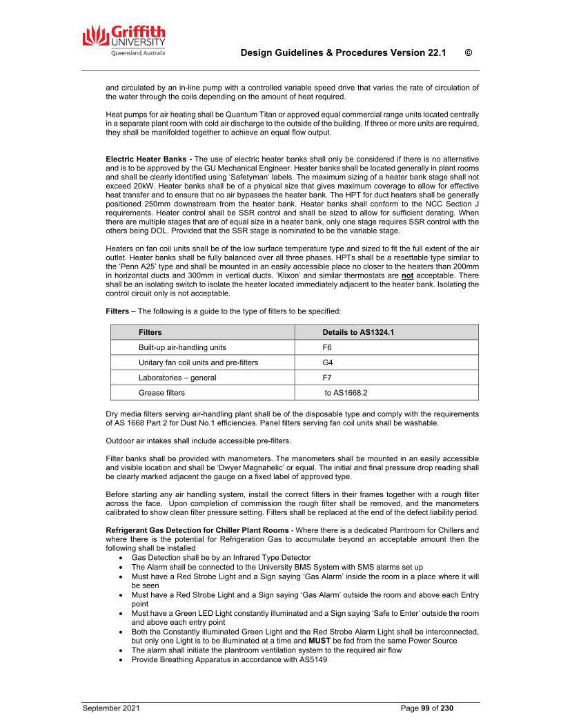
Design Guidelines & Procedures Version 22.1 ©
September 2021 Page 99 of 230
and circulated by an in-line pump with a controlled variable speed drive that varies the rate of circulation of the water through the coils depending on the amount of heat required. Heat pumps for air heating shall be Quantum Titan or approved equal commercial range units located centrally in a separate plant room with cold air discharge to the outside of the building. If three or more units are required, they shall be manifolded together to achieve an equal flow output. Electric Heater Banks - The use of electric heater banks shall only be considered if there is no alternative and is to be approved by the GU Mechanical Engineer. Heater banks shall be located generally in plant rooms and shall be clearly identified using ‘Safetyman’ labels. The maximum sizing of a heater bank stage shall not exceed 20kW. Heater banks shall be of a physical size that gives maximum coverage to allow for effective heat transfer and to ensure that no air bypasses the heater bank. The HPT for duct heaters shall be generally positioned 250mm downstream from the heater bank. Heater banks shall conform to the NCC Section J requirements. Heater control shall be SSR control and shall be sized to allow for sufficient derating. When there are multiple stages that are of equal size in a heater bank, only one stage requires SSR control with the others being DOL. Provided that the SSR stage is nominated to be the variable stage. Heaters on fan coil units shall be of the low surface temperature type and sized to fit the full extent of the air outlet. Heater banks shall be fully balanced over all three phases. HPTs shall be a resettable type similar to the ‘Penn A25’ type and shall be mounted in an easily accessible place no closer to the heaters than 200mm in horizontal ducts and 300mm in vertical ducts. ‘Klixon’ and similar thermostats are not acceptable. There shall be an isolating switch to isolate the heater located immediately adjacent to the heater bank. Isolating the control circuit only is not acceptable. Filters – The following is a guide to the type of filters to be specified:
Filters Details to AS1324.1
Built-up air-handling units F6
Unitary fan coil units and pre-filters G4
Laboratories – general F7
Grease filters to AS1668.2
Dry media filters serving air-handling plant shall be of the disposable type and comply with the requirements of AS 1668 Part 2 for Dust No.1 efficiencies. Panel filters serving fan coil units shall be washable. Outdoor air intakes shall include accessible pre-filters. Filter banks shall be provided with manometers. The manometers shall be mounted in an easily accessible and visible location and shall be ‘Dwyer Magnahelic’ or equal. The initial and final pressure drop reading shall be clearly marked adjacent the gauge on a fixed label of approved type. Before starting any air handling system, install the correct filters in their frames together with a rough filter across the face. Upon completion of commission the rough filter shall be removed, and the manometers calibrated to show clean filter pressure setting. Filters shall be replaced at the end of the defect liability period. Refrigerant Gas Detection for Chiller Plant Rooms - Where there is a dedicated Plantroom for Chillers and where there is the potential for Refrigeration Gas to accumulate beyond an acceptable amount then the following shall be installed
Gas Detection shall be by an Infrared Type Detector The Alarm shall be connected to the University BMS System with SMS alarms set up Must have a Red Strobe Light and a Sign saying ‘Gas Alarm’ inside the room in a place where it will
be seen Must have a Red Strobe Light and a Sign saying ‘Gas Alarm’ outside the room and above each Entry
point Must have a Green LED Light constantly illuminated and a Sign saying ‘Safe to Enter’ outside the room
and above each entry point Both the Constantly illuminated Green Light and the Red Strobe Alarm Light shall be interconnected,
but only one Light is to be illuminated at a time and MUST be fed from the same Power Source The alarm shall initiate the plantroom ventilation system to the required air flow Provide Breathing Apparatus in accordance with AS5149
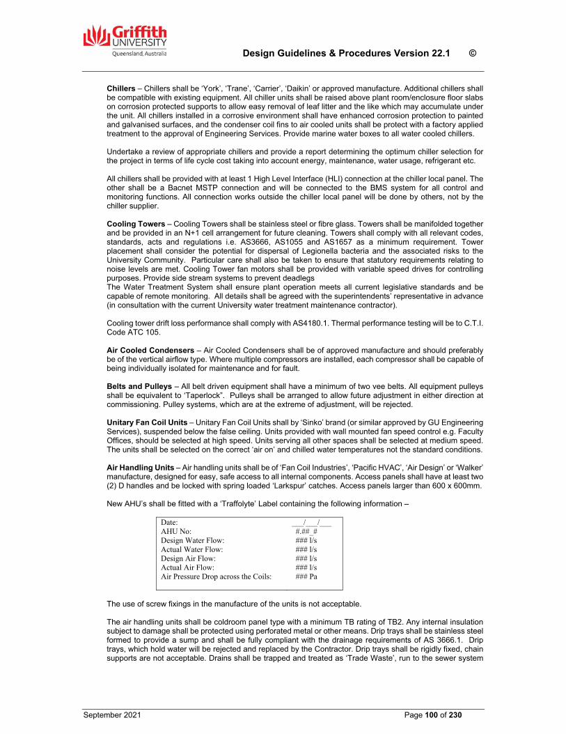
Design Guidelines & Procedures Version 22.1 ©
September 2021 Page 100 of 230
Chillers – Chillers shall be ‘York’, ‘Trane’, ‘Carrier’, ‘Daikin’ or approved manufacture. Additional chillers shall be compatible with existing equipment. All chiller units shall be raised above plant room/enclosure floor slabs on corrosion protected supports to allow easy removal of leaf litter and the like which may accumulate under the unit. All chillers installed in a corrosive environment shall have enhanced corrosion protection to painted and galvanised surfaces, and the condenser coil fins to air cooled units shall be protect with a factory applied treatment to the approval of Engineering Services. Provide marine water boxes to all water cooled chillers. Undertake a review of appropriate chillers and provide a report determining the optimum chiller selection for the project in terms of life cycle cost taking into account energy, maintenance, water usage, refrigerant etc. All chillers shall be provided with at least 1 High Level Interface (HLI) connection at the chiller local panel. The other shall be a Bacnet MSTP connection and will be connected to the BMS system for all control and monitoring functions. All connection works outside the chiller local panel will be done by others, not by the chiller supplier. Cooling Towers – Cooling Towers shall be stainless steel or fibre glass. Towers shall be manifolded together and be provided in an N+1 cell arrangement for future cleaning. Towers shall comply with all relevant codes, standards, acts and regulations i.e. AS3666, AS1055 and AS1657 as a minimum requirement. Tower placement shall consider the potential for dispersal of Legionella bacteria and the associated risks to the University Community. Particular care shall also be taken to ensure that statutory requirements relating to noise levels are met. Cooling Tower fan motors shall be provided with variable speed drives for controlling purposes. Provide side stream systems to prevent deadlegs The Water Treatment System shall ensure plant operation meets all current legislative standards and be capable of remote monitoring. All details shall be agreed with the superintendents’ representative in advance (in consultation with the current University water treatment maintenance contractor). Cooling tower drift loss performance shall comply with AS4180.1. Thermal performance testing will be to C.T.I. Code ATC 105. Air Cooled Condensers – Air Cooled Condensers shall be of approved manufacture and should preferably be of the vertical airflow type. Where multiple compressors are installed, each compressor shall be capable of being individually isolated for maintenance and for fault. Belts and Pulleys – All belt driven equipment shall have a minimum of two vee belts. All equipment pulleys shall be equivalent to ‘Taperlock”. Pulleys shall be arranged to allow future adjustment in either direction at commissioning. Pulley systems, which are at the extreme of adjustment, will be rejected. Unitary Fan Coil Units – Unitary Fan Coil Units shall by ‘Sinko’ brand (or similar approved by GU Engineering Services), suspended below the false ceiling. Units provided with wall mounted fan speed control e.g. Faculty Offices, should be selected at high speed. Units serving all other spaces shall be selected at medium speed. The units shall be selected on the correct ‘air on’ and chilled water temperatures not the standard conditions. Air Handling Units – Air handling units shall be of ‘Fan Coil Industries’, ‘Pacific HVAC’, ‘Air Design’ or ‘Walker’ manufacture, designed for easy, safe access to all internal components. Access panels shall have at least two (2) D handles and be locked with spring loaded ‘Larkspur’ catches. Access panels larger than 600 x 600mm. New AHU’s shall be fitted with a ‘Traffolyte’ Label containing the following information –
Date: AHU No: Design Water Flow: Actual Water Flow: Design Air Flow: Actual Air Flow: Air Pressure Drop across the Coils:
___/___/___ #.##_# ### l/s ### l/s ### l/s ### l/s ### Pa
The use of screw fixings in the manufacture of the units is not acceptable. The air handling units shall be coldroom panel type with a minimum TB rating of TB2. Any internal insulation subject to damage shall be protected using perforated metal or other means. Drip trays shall be stainless steel formed to provide a sump and shall be fully compliant with the drainage requirements of AS 3666.1. Drip trays, which hold water will be rejected and replaced by the Contractor. Drip trays shall be rigidly fixed, chain supports are not acceptable. Drains shall be trapped and treated as ‘Trade Waste’, run to the sewer system
Design Guidelines & Procedures Version 22.1 ©
September 2021 Page 101 of 230
by means of a tundish. Traps shall be easily removable by means of pressure barrel unions. The face velocity at the cooling coil shall not exceed 2.3 m/s. Ensure plinth heights are of sufficient height to allow for the required air gap between the condensate drain and the tundish as per AS/NZS 3500.2 requirements. AHU fans shall be EC Plug type fans selected for high efficiency and low noise, Equipment Location – All equipment shall be located in easily accessible and adequately sized plant rooms unless otherwise approved by the Superintendent. Clearances around the mechanical switchboards shall meet the requirements of AS 3000.
Air-Conditioning Electrical System Switchboards and Motor Control Centres shall normally be of type-tested construction with an IP rating approved by the Superintendent prior to tendering. Switchboards shall be electrical orange (X15 to AS 2700) externally and white internally. External switchboards shall be constructed from powder coated 304 stainless steel. All components shall be located on the rear panel in an orderly manner. No components are to be mounted on the sides or base of the switchboard, and they shall be mounted not less than 300mm above the floor. Permanent, clearly legible ‘Traffolyte’ labels shall be screw fixed to all internal and external controls. Provide a screw fixed ‘Traffolyte’ label to the front of the MSSB that includes the following:
Size and origin of the sub-mains Fire Alarm Relays shall be provided in accordance with the requirements of AS 1668 and AS 1670 as applicable. Provide spare space and capacity in all switchboards, sub-boards and control panels to allow for future expansion. This spare capacity also applies to the switchboard sub-mains etc. The amount of spare capacity shall suit the situation and be agreed upon and approved by the Superintendent prior to manufacture, but in no instance shall be less than 10%. A Polyphase kilowatt-hour meter complete with pulsed output to the BMS shall be provided to the air-conditioning section on the main electrical switchboard. This meter shall be suitably labelled and grouped with all other meters. Refer to Section 20.00 Clause 20.08 for further details of meter installation. All cables shall be run on cable trays, ladders, catenary wire etc and terminated in terminal strips. All cables entering switchboards shall enter the switchboards through a gland nut and be terminated on a terminal block, labelled as to its origin and numbered. All active, neutral, earth and control wiring shall be number ferruled both in the switchboard and at field terminations corresponding to circuit breaker numbers. Wrap around tape numbering systems are not acceptable to the Superintendent. Multi-joining of cables prior to termination on bars is not acceptable. Neutral and earth bars shall have the same number of terminations as circuit breaker positions and shall include two grub screws per terminal. All cabling shall comply with the requirements of Section 20.00 Electrical Services. The MSSB shall include ‘Auto/Off/Manual’ switches for each piece of equipment served except for VAV boxes which will have a heater ‘Auto/Off/Manual’ switch (refer to GU Standard Drawing No. GSD–600, as noted in section 31 of this document gives link to internet site). For all VAV heater banks, an HPT fault indicator light for each VAV unit shall also be provided on the MSSB fascia. Approved electrical and control drawings shall be prepared and supplied with the switchboard by the Date of Practical Completion. Provide a fluorescent lamp in each switchboard cupboard greater than 2m2 in face area. All mechanical switchboards shall have a lamp test facility incorporated into the control system via relays and not diodes. All mechanical boards with BMS control shall have the low voltage and BMS controls mounted on the right-hand side of the board while the 240V/415V equipment shall be mounted on the left-hand side. Separate BMS boards will only be accepted where approved by the Superintendent. All boards shall be adequately vented to remove heat and locked via an ‘L&F 92268’ key. A triple RJ45 socket shall be installed within the BMS board

Design Guidelines & Procedures Version 22.1 ©
September 2021 Page 102 of 230
in a location that is determined by the controls system installer to enable the board to be connected to the GU network. BMS cables shall be screened and not run adjacent to any 240V electrical cables. Separate ducting shall be provided within the switchboard to separate BMS and power cables. The electrical supply to mechanical sub-boards must be taken from the main mechanical switchboard or the mechanical services section of the building MSB. Under no circumstances shall the electrical supply be taken from the buildings general light and power distribution boards. All Electrical & Mechanical services inside the ceiling void which will generate heat such as recessed light fittings, transformers etc. shall not be covered by any thermal insulation or the like which will impede the heat rejection. For small transformers, it is suggested that they be hung on independent support wires.
Identification of Pipework & Ductwork All pipes and ductwork shall be identified in accordance with AS 1345 – Identification of the contents of Piping, Conduits and Ducts, and AS 1318 – SAA industrial Safety Colour Code and AS 2700 – Colour Standards for General Purposes. Extra labelling shall be provided if requested by the Superintendent for clear identification of any pipework or ductwork. Colours as follows;
Chilled water pipes – Green Condenser Water pipework – Galvanised finish Ductwork – Yellow Gas pipework – confirm with Engineering Services
The location of identification marking shall be at intervals of not more than 3m and adjacent to branches, junctions, valves, both sided of walls and control points. Such marking shall be placed so that they are easily seen from all approaches. Safety colours where applied shall be over a length on not less than 75mm at locations and intervals as nominated for ground colours ‘Safetyman’ adhesive labels are an acceptable method for identification of pipework. Flow direction arrows shall be provided to all pipework and the Flow and Return-pipes shall be identified with labels, which read ‘Chilled Water Flow’ and ‘Chilled Water Return’ as appropriate.
Future Expansion & Construction Proper consideration must be given to the design of mechanical services which initially will not be fully utilised or which form part of a Master Plan. Design issues to be considered shall include but not be limited to chilled water supply, size of plant rooms, provision and/or size of service ducts and risers, capacity of equipment, electrical supplies etc. These requirements shall be confirmed by GU.
Building Management System (BMS) The majority of the existing buildings on campus are provided with Schneider Electric ‘Struxureware’ BMS systems with some INet and Vista controllers remaining. All refurbishment shall generally be ‘Struxureware’ or as discussed and agreed with GU Engineering Services. For new buildings, where the system is independent of any existing installation, then an alternative system of approved manufacture, with equivalent technical performance to the Schneider ‘Struxureware’ system, may be considered. If an alternative system is approved following and evaluation by GU, the system manufacturer shall provide all necessary software and training to permit the University’s engineering and maintenance staff to perform remote control, monitoring and other related functions on the existing BMS central computer hardware. The mechanical engineering consultant shall consult with GU Engineering Services and the approved specialist BMS provider to develop a functional brief for the air conditioning control strategy for all areas of a new building or a major refurbishment before design documentation is commenced. The functional brief shall identify the space, space usage, specific requirements and any other considerations that may be considered necessary to achieve the desired control strategy.
Design Guidelines & Procedures Version 22.1 ©
September 2021 Page 103 of 230
All AHUs and FCUs which do not have a requirement for a Constant Temperature Set Point, shall have an Effective Set Point calculated by combining the sum of the Base Set Point +/- Global Offset +/- Local Offset Air-handling units serving individual areas such as lecture theatres. computer labs, seminar, tutorial and meeting rooms, shall be controlled by Movement Detector operated switching with adjustable time delay of at least 30 minutes to some areas. The detector shall be specially designed for energy management purposes and be approved by GU. More than one sensor may be required to cover the entire area. Where movement detectors are used, the sensor only will be installed in the space and the switching relays located in plant rooms. Over-riding time control shall be provided by means of the BMS. All ducted AHUs and FCUs shall have a Supply Air temperature sensor in the Supply Air duct, if a heater bank exists it is to be located at least four duct equivalent diameters after the heater bank. Air handling units serving diverse areas or general offices shall be fully automatic in operation and shall be provided with time switch controls. Time programming shall be provided through the BMS. After hours push buttons shall be provided where required. Air handling units connected to VAV boxes shall have a variable speed drive controlled by a duct pressure sensor providing feedback on the drive speed. Refrigeration plant shall be fully automatic and shall normally respond to a call for cooling from any air-handling unit. Local exhaust fans (other than toilet exhaust) all be provided with local manual controls. Provision shall be made on all controls and sensors for connection to a BMS in accordance with Appendix A to this Section. Control and monitoring systems for air-conditioning plant shall be determined in consultation with staff of GU Engineering Services prior to finalisation of the Specification. Refer to the Points List at the end of this Section 18.0 for the minimum requirements. Chilled water pump controls shall incorporate pressure switches on the suction and discharge sides of the pump, wired in series with the control to the chiller contractor to act as an interlock. Dual secondary/tertiary chilled water pumps shall be fitted complete with variable speed drives with the control such that both pumps will ramp up to maintain the required flow. When the flow decreases below 65% the lag pump will shut down and the lead pump will speed up to maintain the flow. In either case the pump shall be controlled by a differential pressure switch located two-thirds along the Index run of the respective chilled water system. All BMS installations shall be carried out by Specialist Contractors approved by the Superintendent. Power to the BMS control panels shall be 240V/24V with capacity to operate the maximum relays controlled by the BMS. All controls emanating from the BMS to external devices shall be 24VDC or 24VAC originating from a 240V/24V transformer mounted within the BMS section of the MSSB and switched by the internal relays within the BMS control panel. A double RJ45 data port shall be installed on the wall adjacent to and outside the BMS section of the MSSB. The exception to this is where there are environmental conditions that need to be considered (e.g. Outside). The Specialist Contractor shall provide not less than eight hours of operational and programming instruction on the BMS system to staff nominated by the Superintendent. Refer to Appendix A to this Section for minimum requirements. All new chiller and heater bank loads shall be connected to the existing Demand Control program modules. Relevant temperature set points shall be connected to the existing Global Temperature Reset program modules. Where a building is stand alone with respect to Supply Authority Metering, i.e. not existing Demand Control or temperature reset programming, Demand Control and Global Temperature Reset programming shall be provided as part of the contract. Laboratories and some other special areas shall be exempt. Provide a GU approved UPS with power monitoring card to be housed in the BMS switchboard in each building. The UPS shall be fed from a dedicated special pin power point located within the switchboard and suitably signed with an engraved ‘Traffolyte’ label. The BMS will monitor a set of dry contacts in the UPS and send an SMS message to notify nominated persons in the event of an interruption to the building power supply.

Design Guidelines & Procedures Version 22.1 ©
September 2021 Page 104 of 230
BMS software, algorithm and graphics may be based around what has been previously accepted by GU on similar projects, however they must be specifically developed for the particular project and not directly copied from a previous project.
De-humidification Control
Control of all dehumidification to be in accordance with the flow chart below unless approved in writing by Engineering Services:
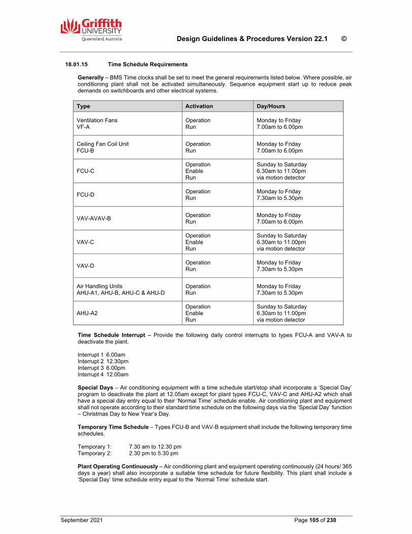
Design Guidelines & Procedures Version 22.1 ©
September 2021 Page 105 of 230
Time Schedule Requirements Generally – BMS Time clocks shall be set to meet the general requirements listed below. Where possible, air conditioning plant shall not be activated simultaneously. Sequence equipment start up to reduce peak demands on switchboards and other electrical systems.
Type Activation Day/Hours
Ventilation Fans VF-A
Operation Run
Monday to Friday 7.00am to 6.00pm
Ceiling Fan Coil Unit FCU-B
Operation Run
Monday to Friday 7.00am to 6.00pm
FCU-C Operation Enable Run
Sunday to Saturday 6.30am to 11.00pm via motion detector
FCU-D Operation Run
Monday to Friday 7.30am to 5.30pm
VAV-AVAV-B Operation Run
Monday to Friday 7.00am to 6.00pm
VAV-C Operation Enable Run
Sunday to Saturday 6.30am to 11.00pm via motion detector
VAV-D Operation Run
Monday to Friday 7.30am to 5.30pm
Air Handling Units AHU-A1, AHU-B, AHU-C & AHU-D
Operation Run
Monday to Friday 7.30am to 5.30pm
AHU-A2 Operation Enable Run
Sunday to Saturday 6.30am to 11.00pm via motion detector
Time Schedule Interrupt – Provide the following daily control interrupts to types FCU-A and VAV-A to deactivate the plant. Interrupt 1 6.00am Interrupt 2 12.30pm Interrupt 3 6.00pm Interrupt 4 12.00am Special Days – Air conditioning equipment with a time schedule start/stop shall incorporate a ‘Special Day’ program to deactivate the plant at 12.05am except for plant types FCU-C, VAV-C and AHU-A2 which shall have a special day entry equal to their ‘Normal Time’ schedule enable. Air conditioning plant and equipment shall not operate according to their standard time schedule on the following days via the ‘Special Day’ function – Christmas Day to New Year’s Day. Temporary Time Schedule – Types FCU-B and VAV-B equipment shall include the following temporary time schedules. Temporary 1: 7.30 am to 12.30 pm Temporary 2: 2.30 pm to 5.30 pm Plant Operating Continuously – Air conditioning plant and equipment operating continuously (24 hours/ 365 days a year) shall also incorporate a suitable time schedule for future flexibility. This plant shall include a ‘Special Day’ time schedule entry equal to the ‘Normal Time’ schedule start.
Design Guidelines & Procedures Version 22.1 ©
September 2021 Page 106 of 230
Control – Ventilation Fans Provide controls to ventilation fans as follows;
VF-A (e.g. General, toilet exhausts) – Start fan according to time schedule. If the fan (e.g. toilet exhaust) also runs with an AC unit, then interlock the exhaust with the AC unit’s time schedule.
VF-B (e.g. Plantroom exhausts) – Cycle fan to maintain room temperature within the specified band.
VF-C (Lift motor rooms) – Cycle fan to maintain room temperature within the specified band. Raise alarm when temperature reaches upper limit. Hard wired from local lift MSB not on BMS – only the alarm on the BMS
VF-D (Fume Cupboards) – fume cupboard has its own controls for fan switching and fan speed control dependant on door opening. Monitor status, fault and fan speed at the fume cupboard terminal strip.
Control – Ceiling Fan Coil Units
Where a single Motion Detector (MD) in an area controls both the A/C and the lighting, there must be a way to turn each off individually by the User e.g. power the MD first then to individual switches for the light and A/C. It is less problematic where there is individual MD’s for the A/C and the lights. Provide time scheduled control of Fan Coil Units as follows;
FCU-A (Staff Offices) – Provide a wall mounted controller with three (3) fan speed settings plus an Auto speed function, motion detection and temperature set point adjustment. Initial activation of the FCU shall be via a start/stop button on the controller and activation shall be maintained by a 3600 ceiling mounted motion detector with a 20 minute (adjustable) minimum running period. The button on the controller shall provide the option to turn off the FCU whilst the room is still occupied (overriding the motion detector). The controller shall also have a local temperature adjustment to allow the occupant to adjust their temperature set point by a maximum of 1.5o C either side of the set point.
FCU-B (e.g. Areas operating continuously) – Provide a daily time schedule to limit the operating hours of the unit. A sensor shall monitor the room temperature and the set point shall be maintained by modulating the chilled water valve to cycle with the heater.
FCU-C (e.g. seminar rooms, laboratories and meeting/conference rooms) - Provide a daily time schedule to limit the operating hours of the unit. Activation of the unit shall be via a motion detector, and the unit shall stop if no motion is detected after 20 minutes. A sensor shall monitor the room temperature and the set point shall be maintained by modulating the chilled water valve to cycle with the heater.
FCU-D (e.g. General Areas) - Provide a daily time schedule to limit the operating hours of the unit. Activation of the unit outside the scheduled hours shall be via a push button, and the unit shall run for a maximum period of 2 hours. A sensor shall monitor the room temperature and the set point shall be maintained by modulating the chilled water valve to cycle with the heater.
Control – Variable Air Volume Boxes (VAV’s)
Provide time schedule control of VAVs as follows;
VAV-A (Staff Offices) - Provide a daily time schedule to limit the operating hours of the unit. Activation of the unit shall be via a motion detector, and the unit shall stop if no motion is detected after 20 minutes. A sensor shall monitor the room temperature and the set point shall be maintained by modulating the VAV damper between its minimum and maximum positions in cycle with heater activation.
VAV-B (e.g. Areas operating continuously) – Provide a daily time schedule to limit the operating hours of the unit. A sensor shall monitor the room temperature and the set point shall be maintained by modulating the VAV damper between its minimum and maximum positions in cycle with heater activation.
VAV-C (e.g. Seminar Rooms, laboratories and meeting/conference rooms) - As for VAV-A above
VAV-D (e.g. General Areas) - Provide a daily time schedule to limit the operating hours of the unit. Activation of the unit outside the scheduled hours shall be via a push button, and the unit shall run for a maximum period of 2 hours (adjustable). A sensor shall monitor the room temperature and the set point shall be
Design Guidelines & Procedures Version 22.1 ©
September 2021 Page 107 of 230
maintained by modulating the VAV damper between its minimum and maximum positions in cycle with heater activation.
Control – Air Handling Units (AHUs) Provide control of AHUs where applicable as follows;
Supply Air – All AHUs shall have a temperature sensor fitted to the unit air supply.
Chilled Water Flow to Coils - Wherever possible (AHU’s over 750l/s), AHUs shall be fitted with split coils in the ratio of 30% and 70%. Each coil shall be fitted with a chilled water supply valve controlled by the BMS. The valve is to be controlled in series with the small coil valve to be opened first. Economy Cycle – Air handling units within systems which utilise an economy mode shall have temperature and humidity sensors installed in the return air. The BMS shall be programmed to calculate the enthalpy of the return air. This enthalpy calculation shall be compared with the enthalpy reading at the campus weather station and the unit shall then be controlled to the most efficient mode. Economy cycles will only be required as per NCC Section J. Carbon dioxide control – a lifecycle cost analysis shall be provided by the consultant to confirm benefits of any proposed CO2 control. Provision for access for sensor calibration shall be specified on the drawings.
Provide time schedule control of AHUs as follows;
AHU-A1 (Single zone unit) – Provide a daily time schedule to limit the operating hours of the unit. Activation of the unit outside the scheduled hours shall be via a push button, and the unit shall run for a maximum period of 2 hours. A sensor shall monitor the room temperature and the set point shall be maintained by modulating the chilled water valve to cycle with the heater bank/coil.
AHU-A2 (Single zone unit) - Provide a daily time schedule to limit the operating hours of the unit. Activation of the unit shall be via a motion detector, and the unit shall stop if no motion is detected after 20 minutes. A sensor shall monitor the room temperature and the set point shall be maintained by modulating the chilled water valve to cycle with the heater bank/coil.
AHU-B (VAV unit) - Provide a daily time schedule to limit the operating hours of the unit. Activation of the unit outside the scheduled hours shall be via a push button, and the unit shall run for a maximum period of 2 hours. VAV cooling demand shall be determined by selecting the highest reading from multiple sensors and reset the supply air temperature set point between 120C and 200C as the maximum cooling demand varies from maximum to nil. The supply air temperature set point shall be maintained by modulating the chilled water valve to cycle with the heater bank/coil. Modulate the VSD to the supply fan to maintain supply air pressure at the set point.
AHU-C (Multi zone face and bypass unit) - Provide a daily time schedule to limit the operating hours of the unit. Activation of the unit outside the scheduled hours shall be via a push button, and the unit shall run for a maximum period of 2 hours. Modulate the zone face and bypass dampers to cycle with the heaters to maintain the zone set point. Zone cooling demand shall be determined by selecting the highest reading from multiple sensors and reset the temperature set point of the supply air off the coils between 120C and 200C as the maximum cooling demand varies from maximum to nil. The control of the chilled water supply to the coils to maintain the off coil air temperature set point is described elsewhere in this clause. Bypass dampers shall adopt the full face position on the shutdown of the AHU.
AHU-D (Single zone DX unit) - Provide a daily time schedule to limit the operating hours of the unit. Activation of the unit outside the scheduled hours shall be via a push button, and the unit shall run for a maximum period of 2 hours. A sensor shall monitor the room temperature and the set point shall be maintained by cycling cooling and heating modes.
AHU-E Lecture Theatres – Provide a daily time schedule. Start the AHU 20 minutes prior to the commencement of the first lecture for the day and run the AHU on at a relaxed temperature if the next lecture is less than 1 hour away – relaxation to 27°C in Summer and 19°C in winter.
Design Guidelines & Procedures Version 22.1 ©
September 2021 Page 108 of 230
Control – Chilled water Primary Chilled Water System (Chillers) – The temperature sensor in the return line in the chilled water loop shall control the sequencing of the chiller units in a chilled water generation plant. Step Up time shall be dynamic varying from thirty (30) minutes to two (2) minutes depending on the temperature differential between common return chilled water and the Step Up temperature set point. Step Down time shall be dynamic varying from thirty (30) minutes to two (2) minutes depending on the temperature differential between common return chilled water and the Step Down temperature set point. Settle time shall be dynamic varying from thirty (30) minutes to fifteen (15) minutes depending on the temperature differential between common return chilled water and the Step Up and Step Down temperature set points. The following control/monitoring points shall be able to be forced with an indicator;
Common entering return chilled water temperature Total Chiller load % in actual kW refrigeration Master cooling call
The following control points shall be adjustable;
Set Up temperature set point Step Down temperature set point Step Up load % set point Step Down load % set point Step Up time controller Step down time controller Settle time controller Chiller sequence
The following control points shall not be changeable from the graphics page and shall be dynamic;
Set Up time Step Down time Settle time
Chiller Units Graphics Page – Each chiller unit shall have its own graphics page. If a chiller is in fault or fails to start, then a command to start shall be passed to the next chiller in available sequence. The sequence in which the chillers are operating shall be highlighted on each chiller graphics page. Chilled Water Reticulation Graphics Page – The sequence in which the chillers are operating shall be highlighted on the page. The following points shall be able to be forced with an indicator;
Change lead chiller/pump Secondary chilled water pump start/stop Pump VSD speed Cooling call
If secondary chilled water pumps in a building on the chilled water loop are running, and the building return water temperature is greater than the Step Up temperature set point for more than ten (10) minutes and no chillers are running, then a signal shall be given to start the lead chiller. Generally, precinct systems shall be Primary/Secondary/Tertiary systems so that each element of the system is not affected by the others. Primary Chilled Water System – Modulate the primary CHW pump VSD speed to maintain the optimum chilled water flow through the chillers. This flow may vary depending on the chillers selected. The flow shall be managed to maintain the optimum operation of the chillers. It is preferred for the chillers to be controlled via the chiller manufacturers proprietary control system – not the BMS.
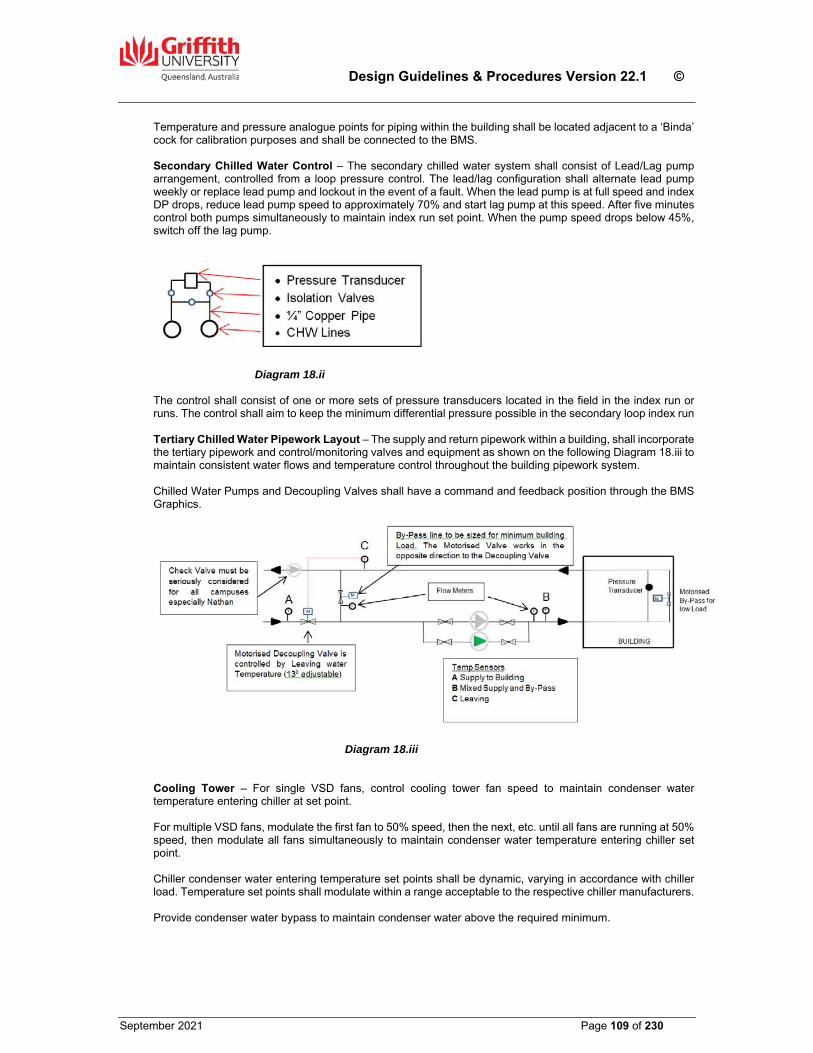
Design Guidelines & Procedures Version 22.1 ©
September 2021 Page 109 of 230
Temperature and pressure analogue points for piping within the building shall be located adjacent to a ‘Binda’ cock for calibration purposes and shall be connected to the BMS. Secondary Chilled Water Control – The secondary chilled water system shall consist of Lead/Lag pump arrangement, controlled from a loop pressure control. The lead/lag configuration shall alternate lead pump weekly or replace lead pump and lockout in the event of a fault. When the lead pump is at full speed and index DP drops, reduce lead pump speed to approximately 70% and start lag pump at this speed. After five minutes control both pumps simultaneously to maintain index run set point. When the pump speed drops below 45%, switch off the lag pump.
Diagram 18.ii The control shall consist of one or more sets of pressure transducers located in the field in the index run or runs. The control shall aim to keep the minimum differential pressure possible in the secondary loop index run Tertiary Chilled Water Pipework Layout – The supply and return pipework within a building, shall incorporate the tertiary pipework and control/monitoring valves and equipment as shown on the following Diagram 18.iii to maintain consistent water flows and temperature control throughout the building pipework system. Chilled Water Pumps and Decoupling Valves shall have a command and feedback position through the BMS Graphics.
Diagram 18.iii Cooling Tower – For single VSD fans, control cooling tower fan speed to maintain condenser water temperature entering chiller at set point. For multiple VSD fans, modulate the first fan to 50% speed, then the next, etc. until all fans are running at 50% speed, then modulate all fans simultaneously to maintain condenser water temperature entering chiller set point. Chiller condenser water entering temperature set points shall be dynamic, varying in accordance with chiller load. Temperature set points shall modulate within a range acceptable to the respective chiller manufacturers. Provide condenser water bypass to maintain condenser water above the required minimum.
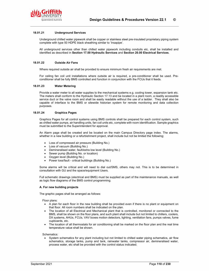
Design Guidelines & Procedures Version 22.1 ©
September 2021 Page 110 of 230
Underground Services Underground chilled water pipework shall be copper or stainless steel pre-insulated proprietary piping system complete with type 50 HDPE black sheathing similar to ’Insapipe’. All underground services other than chilled water pipework including conduits etc, shall be installed and identified as described in Section 17.00 Hydraulic Services and Section 20.00 Electrical Services.
Outside Air Fans Where required outside air shall be provided to ensure minimum fresh air requirements are met. For ceiling fan coil unit installations where outside air is required, a pre-conditioner shall be used. Pre-conditioner shall be fully BMS controlled and function in conjunction with the FCUs that it feeds.
Water Metering Provide a water meter to all water supplies to the mechanical systems e.g. cooling tower, expansion tank etc. The meters shall conform to the Hydraulic Section 17.13 and be located in a plant room, a readily accessible service duct or the valve room and shall be easily readable without the use of a ladder. They shall also be capable of interface to the BMS or sitewide historian system for remote monitoring and data collection purposes.
Graphics Pages Graphics Pages for all control systems using BMS controls shall be prepared for each control system, such as chilled water pumps, air handling units, fan coil units etc, complete with room identification. Sample graphics must be submitted to the Superintendent for approval. An Alarm page shall be created and be located on the main Campus Directory page index. The alarms, whether in a new building or a refurbishment project, shall include but not be limited the following;
Loss of compressed air pressure (Building No.) Loss of vacuum (Building No.) Demineralised water, fault/extra low level (Building No.) Sewer pump (Building No. or location) Oxygen level (Building No.) Power loss/fault - critical buildings (Building No.)
Some alarms will be critical and will need to dial out/SMS, others may not. This is to be determined in consultation with GU and the space/equipment Users. Full schematic drawings (electrical and BMS) must be supplied as part of the maintenance manuals, as well as logic flow diagrams of the BMS control programming. A. For new building projects The graphic pages shall be arranged as follows:
Floor plans: A plan for each floor in the new building shall be provided even if there is no plant or equipment on
that floor. All room numbers shall be indicated on the plan. The location of all Electrical and Mechanical plant that is controlled, monitored or connected to the
BMS, shall be shown on the floor plans, and such plant shall include but not limited to chillers, coolers, DX systems, AHUs, FCUs, VAV boxes motion detectors, lighting, ventilation fans, pumps valves, fume cupboards, etc.
The location of all thermostats for air conditioning shall be marked on the floor plan and the real time temperature value shall be shown.
Schematics: System schematics for any plant including but not limited to chilled water piping schematics, air flow
schematics, storage tanks, pump and tank, rainwater tanks, compressor air, demineralised water, process water, etc shall be provided with the control status indicated.
Design Guidelines & Procedures Version 22.1 ©
September 2021 Page 111 of 230
In general, system schematics for any plant items controlled/monitored by BMS shall be provided on request at no extra cost e.g. process water.
A separate schematic for the BMS shall be provided indicating all the main and sub main controllers, outstations, etc. Each location shall be identified by way of the room number, switchboard number, etc. The make, model and a brief description of each BMS device shall be provided in the form of a Schedule.
If the plant runs according to a time schedule, the graphic shall provide a link to view or modify the time schedule.
Schedules: Schedules with live data shall be provided for any plant including but not limited to AHUs, FCUs, VAVs,
pumps, chillers, cooling towers, lightings, fume cupboards, etc. In general, similar plant on the same floor shall be included in Schedule.
The first column of the Schedules shall indicate the location of that plant e.g. by room number. The second column shall be the equipment item identification number.
The Schedule shall include all details of the plant control and monitoring functions. Every control point or variable shall be indicated in the Schedule. All control values shall have clear units where appropriate e.g. ‘65% opening’ for a modulating valve position; ‘35Hz’ for a VSD output, ’23.5C’ for a temperature reading; ‘2345hr’ for total hour run, etc.
A separate page explaining the control philosophy shall be linked to the Schedule for each plant item. The content shall be brief and a simple explanation of the control logic for that plant item shall be given e.g. ‘FCU1.23 is started by motion detector MD1.23; the fan speed is fixed; the chilled water valve is an ‘on/off’ type controlled by the room wall mount thermostat; the cooling temperature is preset at 23.5C and subject to Global Temperature Reset; the heater is at 2 stages, the heating temperature is preset at 21.5°C and subject to Global Temperature Reset’
The location of all BMS controllers and devices shall be noted on the Schedule.
Load up sequence: The graphics page for a building shall contain links to each floor, system schematic and Schedule. The screen for each floor shall also have links to access the relevant schematics or Schedules. It must be possible to navigate via links to a previous page, or to the first page at any point.
B. For refurbishment projects
For any major refurbishment of a substantial area of an existing building, the same requirements as for new buildings shall apply, and the existing old graphics shall be decommissioned at the time of Practical Completion.
For minor refurbishments, update the graphics (plant, floor plan and schematics), and functional description to suit the changes.
Energy Management
Seminar, Lecture Theatre and Tutorial style rooms shall be controlled by the use of infra-red motion detectors specially designed for energy management purpose with the overall hours of operation controlled by the BMS. Limits on the hours of operation of all units shall be provided by the time-switching function of the BMS. All spaces with a population exceeding 100 persons or 100% outside air shall be investigated for the use of enthalpy control and/or heat transfer systems on outside air where a cost analysis proves the inclusion viable. Controls, thermostats and motorised dampers to allow for automatic operation on all outside air whenever conditions permit shall be incorporated wherever possible. All chilled water pumps and large air handling units incorporating VAV boxes shall have variable speed, variable frequency drives as manufactured by ‘ABB’ or ‘Danfoss’ with minimal harmonic effect and be capable of being controlled by the BMS for all parameters. HLI interface to BMS required All relevant requirements of Section 17.00 and Section 20.00 shall apply.
Air Conditioning Cooling & Heating Design Setpoints & Control Philosophy For general office and teaching areas, the design of air conditioning systems is intended to achieve space comfort conditions, and therefore the summer and winter indoor Setpoints as previously nominated in Clause 18.01.03 are to be as follows:
Design Guidelines & Procedures Version 22.1 ©
September 2021 Page 112 of 230
Summer - 23.5°C +/-1.0 °C Winter - 21.0°C +/-1.0 °C
This means that on a hot summer day, the room shall be cooled only when the temperature is above the Setpoint of 23.5°C. If the room temperature occasionally drops to lower than 23.5°C, the heater must never be activated to bring the temperature up. Conversely, the same principle shall apply when heating in winter in that the room must never be cooled if the temperature is slightly above 21.C°C. To achieve the above control logic, the control Setpoints of an air conditioning unit, whether it is a FCU or AHU, must be separated into a cooling (summer) Setpoint and a heating (winter) Setpoint. The software programming of the BMS controls shall be arranged in a way that both Setpoints can be adjusted individually, subject to either a manual or an automatic global reset. A ‘Global’ reset is an automatic programme that will adjust the temperature Setpoints when the ambient condition is extreme and outside the design parameters. For instance, when the summer outdoor temperature is at 38.4°C, which is 6.0°C higher than the design condition of 32.4°C, the indoor cooling Setpoint for the whole building shall be increased by 2.0°C to 25.5°C for better energy and comfort management. However, this increase in the cooling Setpoint shall have no effect on the heating Setpoint. Conversely the same principal shall apply in winter with a heating Global reset. For a particular system such as an FCU with a local thermostatic controller, the manual adjustment of the indoor temperature by the user shall only affect the summer cooling Setpoint. While the 23.5°C Setpoint may be varied up to +/-2.0°C for cooling, the heating Setpoint of 21.0°C shall remain unchanged. Both Setpoints shall still be individually subject to a global reset. The above section does not apply to areas with humidity control or specialist requirements for instrumentation, laboratories etc.
Design Requirements for VAV Air Conditioning Systems
The adoption of a VAV system for a new building or major refurbishment shall only be with the approval of the Superintendent, following a detailed review of the proposed design by the GU Mechanical Engineer. In preparing the design of a VAV system, the following guidelines shall be observed;
In general, a VAV system may be used for open plan office areas and large rooms such as multiple of dividable seminar rooms, laboratories and conference rooms.
Each conditioned space shall be properly zoned into perimeter and internal zones. The perimeter zone shall be further divided into North, South, East and West zones if required. The internal zone shall also be divided into more than one zone if the loading patterns differ significantly. Every zone shall be served by an individual AHU. This aims to avoid simultaneous cooling and heating requirements within the same zone at any time.
The minimum opening of the VAV box shall be set at 40% to achieve the best savings in energy consumption. This setting can be adjusted slightly up or down to suit the particular requirements of an area, however with the reduced minimum flow and proper zoning as outlined above, the possibility of having to provide heating to an overcooled space will be much reduced.
For better air distribution and to minimise cold air dumping during low air flow, linear slot type diffusers shall be used instead of louvre type.
A ‘start/stop’ push button with an indicator light shall be provided for each and every VAV box such that the user can choose to switch the conditioned air supply for the area served by that box ‘on’ or ‘off’. When the push button for a VAV is at ‘stop’, the box opening shall remain at approximately 5% to maintain a minimal air flow.
One motion detector shall be provided for each VAV box. When the VAV box is operating, the motion detector shall switch the box off if there is no motion detected for 30 minutes. When the VAV box is not operating, the motion detector shall not switch the box or even when motion is detected. The VAV box must be turned on the push button only.
The AHU servicing the zone shall automatically operate during the preset time schedule. Even if all the VAV boxes in the zone are off during the scheduled hours. The AHU shall remain on. The AHU shall not operate outside the scheduled time but if any on of the VAV boxes is turned on using the local push button, the AHU shall be activated. If electric heaters are fitted to the AHU, then the unit fan shall be time delay switched so that it will continue to run on at low speed for a period of five (5) minutes after the shutdown of all VAV boxes in order to dissipate the residual heat from the heater bank.
The fresh air supply to the AHU shall be maintained by a dedicated fan such that the design flow rate of fresh air will be fairly constant even when the supply/return air flow of the AHU is low. The fresh air fan shall operate whenever the AHU fan is on.
Design Guidelines & Procedures Version 22.1 ©
September 2021 Page 113 of 230
The indoor design temperature shall be 23.5°C in summer and 21.0°C in winter. During summer cooling, the VAV damper shall have a minimum opening on 40% when the temperature is at or below 23.5°C, and fully open at 24.5°C. During winter heating, The VAV damper shall always be open at 30% minimum.
The summer and winter indoor design temperatures shall subject to Global Reset as outlined in the previous Clause.
The heaters shall not operate when the indoor temperature is at or above 21.0³C. When the indoor temperature drops to 20.0°C, the heater shall start and step up to full load when indoor temperature drops to 19.0°C. The heater shall switch off when temperature rise to 21.0°C.
Fume Cupboards
General Requirements
The fume cupboard installation and associated services shall be designed, supplied, installed, tested and maintained to the requirements of the following standards:
AS 2243.8 – Safety in Laboratories, Fume Cupboards, AS 2982 – Laboratory Construction AS 60079.10.1 – Classification of Hazardous Areas – Examples of Area Classification – Laboratories
Including Fume Cupboards and Flammable Medical Agents, AS 1482 – Electrical Equipment for Explosive Atmospheres – Protected by Ventilation – Type of
Protection, AS 3000 – Electrical Installations – Buildings, Structures and Premises and the Workplace Health and
Safety Regulations. The requirements of this Clause relate to fume cupboards intended for general chemical use. Further requirements shall be incorporated in fume cupboards intended for special applications as established by the SDFs, e.g. perchloric and HF acid, radioactive substances high hazard operations. Where it is possible that the discharge from the cupboard or group of cupboards is likely to impact an adjacent building or installations, a detailed investigation including wind analysis is to be undertaken before the final design is submitted for consideration. If it is found that the proposed installation will have an adverse impact on the surroundings, recommendations for the elimination of these factors are to be included in the report.
Fume Cupboards Generally Fume cupboards shall be single-sided, of proprietary manufacture and shall be based on a proven standard design. Cupboards shall be dimensions to suit the particular requirements of the SDFs. Cupboards shall be constructed of fire-retardant glass reinforced plastic (GRP) and shall comply with AS1530.3. Fume cupboards shall be ‘Hamilton’, ‘S2M’, ‘Chemical Fume Handling’, ‘or equal approve by GU. Provide an infill panel at the top of each cupboard to the ceiling to conceal the exhaust duct and include a removable access panel to allow for servicing of glass door, pulleys and other equipment. Access panels for maintenance shall be easily accessible. Where multiple cupboards are installed side by side, ensure any access panels in sides of cupboards are not obstructed.
Fume Cupboard Construction Inner Chamber – The inner chamber shall be a single piece moulded design from chemical resistant GRP with large radiused corners. The roof shall be aerodynamically shaped evenly on three sides towards a flanged rectangle outlet at the rear of the chamber which shall not be less than 45% of the width of the inner chamber and containing no exposed fixing bolts. A flat non-aerodynamic type roof will not be acceptable. The inner chamber shall have a smooth finish for ease of maintenance and shall accept any runback from the exhaust. Sash – Access to the fume cupboard shall be via a single 6mm thick safety glass door panel stamped by the manufacturer together with the SAS approval stamp. The door shall slide vertically in special PVC extrusions. The door panel shall be carefully balanced to ensure even and easy operation using stainless steel cables and low friction pulleys. Closure cushions shall be installed at the bottom of the door tracks to allow a 50mm minimum opening.
Design Guidelines & Procedures Version 22.1 ©
September 2021 Page 114 of 230
Front Fascia – The aerodynamically shaped fascia and door assembly having a full length aerofoil section shall be incorporated and constructed to ensure a smooth even airflow pattern entering the fume cupboard. Rear Baffle – Moulded baffles are required at the rear of the cupboard and shall be designed to provide a laminar airflow at all levels and across the width of the cupboard. The baffles shall be readily removable for maintenance. The baffles shall be specifically designed, contain no exposed bolts and allow the whole chamber to be effectively scavenged. Base – The base of the chamber shall contain a full width sump moulded in one piece from GRP and fitted with a waste outlet. Worktop – The worktop shall be as required by the end user and may or may not incorporate a sink. Lighting – Provide a fluorescent light fitting mounted in a purpose made moulded cover and armour plate front panel in the roof of the chamber to provide lighting levels in accordance with AS 2243.8. The light fitting shall not disturb the airflow within the cupboard. The 240V electrical supply and final connection shall be undertaken by the mechanical sub-contractor. The light fitting shall be easily accessed for tube replacement and maintenance, via an access hatch in the front face of the cupboard.
Fume Cupboard Services The fume cupboard can have a range of services including gases, water and electricity, refer to the SDF’s. Service outlets shall generally be located in the inner side walls of the fume cupboard with the sink located under the water outlets. The outlets shall be finished in an electrostatically applied epoxy. Controls to services shall be mounted on the fascia panel below the door. All outlets shall be clearly identified both inside and outside the cupboard at outlets and controls with engraved plastic labels. Provide double GPOs as required appropriately labelled mounted in the bottom half of the vertical fascia, in accordance with AS 2243.8. Each GPO shall come complete with neon indicator lamps and shall be RCD protected. Where a user has nominated a requirement for a scrubbing fume cupboard for the use of perchloric and hydrofluoric acids, a hand-held spray with flexible hose connection shall be provided to allow a gentle cold water washdown of the cupboard interior. This washdown system shall be connected to a dedicated cold water service outlet. See also Clause 18.03.06 of this Section.
Fume Cupboard Support Cupboards shall be mounted at normal bench height and the entire unit shall have a neat aesthetic appearance. Provide disabled access to at least one fume cupboard per laboratory. The support structure shall be designed to support the cupboard and where required in the space description forms, provide storage space complete with adjustable shelving, doors and handles. The rear panel shall be removed to access services run on the back wall.
Sash Activated Velocity Control An electronic control system shall be coupled to the fume cupboard sash to control the speed of the extraction fan and maintain a velocity in accordance with AS 2243.8 across the open sash regardless of position. At minimum sash opening the fume cupboard shall be scavenged at a minimum rate of five (5) air changes per minute. The controller shall be easily accessed for adjustment of minimum and maximum flow rates. A discharge cone could be fitted which ensures a suitable discharge velocity even at minimum exhaust rates.
Control Systems Provide a control system complete with switches, timers, relays, pre and post purge functions and audio/visual alarms in full accordance with AS 2243.8, AS 2430 and AS 1492. Provide a manual reset switch to reset the alarm systems.
Design Guidelines & Procedures Version 22.1 ©
September 2021 Page 115 of 230
The exhaust system shall modulate to maintain negative pressure or inward air flow as required for the specific use of the area. The fume cupboard control system shall incorporate terminals to enable connection of the BMS. These terminals shall provide 2V free contacts for the BMS to monitor the fume cupboard status, and faults. The BMS is required to monitor the fume cupboard status so that the AHU serving the laboratory can be started and continue to run while the fume cupboard is in use even though the laboratory is unattended due to a prolonged experiment or reaction procedure. The fume cupboard manufacturer shall completely pre-wire the fume cupboard. Terminals shall be provided for the single phase electrical supply to the cupboard and the three phase connection between the cupboard and extraction fan.
Fume Exhaust Systems
Noise & Vibration The sound pressure level measured at each fume cupboard with the air conditioning in operation, should not exceed that nomination in AS 2243.8. When all fume cupboards in each laboratory are running at full capacity the overall sound pressure levels within the room shall not exceed the levels in AS2107. All equipment shall be installed so as to prevent vibration.
Exhaust Unit The exhaust fans shall be of the forward curved centrifugal type with overhung wheel, contracted of PVC and being of approve design and manufacture capable of being adjusted to run at 110% of the specified rating. The fan casing shall be fabricated entirely from Chemical resistant reinforced plastic in one piece without seams or joints. The impeller shall be of all PVC welded construction except for a stainless steel centre. Shafts are to be stainless steel, liberal in size to afford rigid support for the overhung fan impeller. All metal parts which may be exposed to corrosive fumes shall be completely covered with PVC. The impeller centre shall be extended outside the fan casing and shall be fitted with a high quality plastic seal which is resistant to chemical corrosion, wear and tear. The motor/fan base shall be constructed of fibreglass and mounted to a concrete plinth via spring or rubber vibration mounts with stainless steel nuts and bolts. Fan bearings shall be of the maintenance free ball or roller type. Fans shall be belt driven with drives designated for the motor starting torque and not less than 150% of the motor rated kW. Belts shall be matched sets, and a minimum of two belts shall be used on each fan. Motors shall be of totally enclosed fan cooled, running at not more than 24 rev/s, and suitable for operation on 3-phase, 415 volt, 50Hz supply. Provide belt guards on all fan drives with DZUS fasteners. Pulleys shall be ‘Taperlock’. A drain connection shall be provided in the bottom of the fan casing. PVC drains shall fun from each fan directly into the Laboratory waste system. Ensure fan drain lines dose not cross access paths creating trip hazards. Exhaust air fans shall be selected for an outlet velocity to comply with AS 2243.8, however where optimum static efficiency can be achieved by exceeding this velocity, an alternative fan selection may be submitted for approval.
Exhaust Fume Scrubbing A combination scrubbing and mist eliminator shall be fitted directly to the outlet of each fume cupboard capable of removing 98% of perchloric acid fumes by weight. Fume scrubbers shall be installed to all new fume cupboards except where specifically excluded in the space description forms. Cupboards not fitted with fume scrubbers shall be constructed with provisions to allow easy fitment at a future date if required.
Design Guidelines & Procedures Version 22.1 ©
September 2021 Page 116 of 230
The scrubber shall be constructed of fire retardant GRP incorporating eliminator pads and spray jet section. Scrubbers shall use recirculated neutralising solution and shall incorporate a storage tank of adequate size at the base of the unit together with all necessary connections, pumps etc, automatic bleeds, make-ups etc. Provide a GRP spillage tray beneath the neutralising tank with raised edges to contain any accidental spillage. The fume scrubber shall be completely pre-plumbed for easy connection to waste plumbing and water supply points provided by the Hydraulics subcontractor. Scrubbers mounted on top of fume cupboards with service access required through walls and ceilings are not acceptable. Adequate service access including visual inspection panels shall be provided through the front only. All ducting shall be labelled with ‘Safetyman’ labels.
Air-Conditioned Make-up Air Supply Conditioned make-up air is required to the laboratory during the operation of the fume cupboards and the quantity of air conditioned make up air shall be proportional to the number of cupboards operating and to the requirements of AS 2243.8. This shall be achieved by the use of static pressure indicators in each cupboard linked to the BMS which shall increase/decrease the speed of Variable Speed Drive fan in the Air Handling Unit together with an adjustment to the blade position of the outside air damper to vary air flow. The makeup cooling system shall provide conditioned air for the full air quantity and to meet the internal lab requirements for both temperature and humidity.
Fume Exhaust Ductwork Ductwork shall be circular Un-plasticised Poly Vinyl Chloride (uPVC) in accordance with the following schedule:
Duct Diameter Minimum Thickness of PVC
Up to 400mm 3mm
410-600mm 4mm
Horizontal ductwork shall be installed with a minimum fall of 1:100 back to the fume cupboard, and shall be adequately supported to prevent flexing, ‘drumming’ or sagging. Welds shall be V-type, using hot air welding equipment, one run of 3mm thick welding rod shall be used for 3mm and 4mm material and 3 runs of 3mm or triple welding rod for material 4.5mm or over. Welding shall be in accordance with AS 1477 Part 5. Exposed exhaust ductwork external to the building shall be an appropriate grade of stainless steel unless it is required to match existing ductwork installations. This shall particularly apply to discharge ductwork projecting above the roof. Provision shall be made in each exhaust duct on the discharge side of the fan for the insertion of pitot tubes to enable air flows to be measured. Provide access openings in the ductwork to enable cleaning of PVC ductwork internally. Access openings shall not be installed in the invert of horizontal ducting. Discharge ducts shall be adequately braced and shall comply with AS 2243.8 and AS 1668.2 for height above roof and discharge velocity, and shall be to the approval of the Air Pollution Council. The final height of discharge stacks shall be determined after consideration of the surrounding environment and the building’s aerodynamic wake. Exhaust stacks should extend above the aerodynamic wake of the building wherever possible. Fire protection shall be provided to all slab penetrations to meet Building Act requirements and to the approval of the Superintendent.
Electrical & Controls All electrical work shall be carried out in accordance with the requirements of Section 20.00 Electrical Services, AS 2430-3 and as described below.
Design Guidelines & Procedures Version 22.1 ©
September 2021 Page 117 of 230
Power to the fume cupboards exhaust and scrubber systems and associated controls and services shall be supplied from the mechanical switchboard serving that area. Provide a control cubicle incorporated within the fume cupboard easily accessible for maintenance for all necessary fuses, relays, timers, contactors etc. Each cubicle shall be fitted with a label which states the sub-boards and fuses which supply that fume cupboard. Power to the GPOs on each fume cupboard shall be supplied from the local electrical sub-board associated with that laboratory and shall use 2 x 15 A circuits. All GPOs must be labelled as per the requirements of Section 20 Electrical Services. In addition to the above requirements, each reticulated system to the laboratory including those points serving the fume cupboards shall be isolated by a local laboratory isolating device as required by AS 2982 located adjacent the exit door. The power to the GPOs on the fume cupboards shall be disconnected by the local sub-board shunt trip and the total gas to the laboratory isolated by operation of a gas solenoid valve on the gas supply line serving the laboratory.
Dangerous Goods & Safety Storage Cabinets The venting of dangerous goods and safety cabinets, unless mandatory under Australian Standards, shall be subject to a risk and safety assessment to be undertaken in conjunction with CLF and the GU Health & Safety Advisor (Chemical & Radiation Safety). Reference shall be made to the following Australian Standards with respect to the design of ventilation systems, duct materials and fan types; AS 1940 – The Storage & Handling of Flammable & Combustible Liquids AS/NZS 5026 – The Storage & Handling of Class 4 Dangerous Goods AS 4326 – The Storage & Handling of Oxidizing Agents AS 2414 – The Storage & Handling of Organic Peroxides AS/NZS 4452 – The Storing & Handling of Toxic Substances
Nederman Arm Extraction Systems
The following requirements are based on the Nederman arm model with pipe size 50mm. For bigger pipe size the air flow data shall be adjusted accordingly.
The design flow rate of each arm shall be within the range of 50m3/hr to 100m3/hr. The low limit is to ensure effective extraction effect and the high limit to avoid excessive noise generated.
The minimum flow shall be increased if extraction hoods bigger than the standard mini hood is being used. The selection of the hood type and size shall be discussed with the Users and it must be noted that bigger hoods require much higher suction flow rates to provide the effective capture velocity. In general, the mini hood is considered sufficient for most applications. The use of mixed hood types in a single room is not recommended, as the air flow balance will be extremely difficult to attain.
Multiple arms in separate rooms may be connected to a common mechanical fan extraction system. Where this occurs, a 100% standby fan shall be provided to enhance reliability of the system. The fans shall be controlled by VSDs with pressure sensors such that when all arms are working, the minimum flow of each arm can be maintained, and when only one arm is working, the flow shall be under the maximum design value. If the above cannot be achieved due to too many arms, then multiple separated extraction systems shall be adopted.
A motorised zone damper for each room shall be provided to close off the branch duct when the system in the room is not being used. Each arm shall also come with an integrated manual damper, and the Users are to be encouraged to close it when not in use.
An ON/OFF push button with light indicator shall be provided in the room for the users to activate the system. When the button is pushed ON, the zone damper shall open and the fan shall start. When the button is pushed for OFF, the zone damper shall close and the fan shall stop (note the fan will still run if arms in other rooms on the same system are in use). If the button is ON for a period in excess of 3 hours (this time period shall be adjustable), the room will be switched OFF automatically by the BMS control. The Users have to push it ON again if they wish to continue using the arms.
The whole extraction system shall be connected to the building BMS system for control and monitoring. The BMS graphics shall include a schematic of the system showing all the fans, zone dampers and push button status.
For a system where a common exhaust fan services multiple arms in a number of separate rooms, the fan shall be started when the arms in any one of the rooms is being used. To avoid dead flow of the fan in the case where all manual dampers are closed, at least one arm damper in each room shall be locked open permanently to maintain the air path.
Design Guidelines & Procedures Version 22.1 ©
September 2021 Page 118 of 230
Note that the extraction system shall not be used to maintain any negative pressure requirement of the room such as for PC2 or PC3 labs.
Please refer to the drawing GSD-601 for the indicative schematic of the extraction system with multiple room application.
A smoke test to verify the performance of each Nederman arm shall be carried out in addition to the overall system air flow testing and balancing works as specified in other Sections of the DG&P.
Laboratory Piped Services
LP Gas Pipework shall be Type ‘B’ copper. The minimum sizes shall comply with the latest version of AS/NZS 5601. All joints shall be silver soldered using 15% silver solder. Isolation valves shall be of the ball type. A gas meter shall be provided to the building main supply. All underground pipes shall be pre-lagged to the required colour and all joints colour taped after installation. Pressure reticulation shall be as determined by the relative authority. LP Gas delivered from bulk storage tanks shall include two stage regulation. LP gas stall be reticulated at high pressure after the first stage of regulation from the storage vessel to the building. A second stage regulator shall be provided adjacent the gas meter at each building. MJ/hr ratings for all equipment to be indicated on design drawings along with developed pipework length and pipework materials.
Laboratory Gases Laboratory gases shall conform to the requirements of the following standards:
AS2982 Laboratory Design and Construction AS2896 Medical Gas Systems AS4332 The Storage and Handling of Gases in Cylinders AS2243 Safety in Laboratories
Gases to be supplied from bottles shall be located within a secure ventilated storage compound located external to the building and which is easily accessible from a service road. Where this is not possible or practical e.g. refurbishment projects, the bottles shall be stored internally in an appropriate secure, ventilated store room adjacent to the laboratory readily accessible from the circulation corridors and the building lift for the replacement and removal of gas bottles. Cylinders shall be manifolded with non return valves in such a way that any cylinder can be removed and still allow the effective operation of the pressure manifold. Pipework and valves shall be of a material or type appropriate to the particular gas. Gas pipework shall be tested at 1000kPa or twice the working pressure whichever is the greater. High purity and ultra high purity gases shall be run in 316 stainless steel or equal approved.
Compressed Air Compressed air shall be supplied from a central air compressor station comprising duplicate air compressors and other necessary equipment such as refrigerated dryers, water/oil separators and filtration to meet the proposed User requirements. Compressors shall be from a manufacturer acceptable to GU and shall be fitted with volt free contacts for connection of the BMS to monitor ‘Common Fault’ and ‘Low Pressure’. The quality of the air shall be determined by the User and shall be classified to ISO8573 in terms of particulate, water and oil. The compressor shall be effectively silenced. Pipework shall be type ‘B’ copper with 15% silver soldered joints used for compressed air. All valves shall be ball valves.
Design Guidelines & Procedures Version 22.1 ©
September 2021 Page 119 of 230
Provide a suitably valved connection point outside the compressor plant room for connection of temporary air compressors or bottles.
Vacuum Vacuum shall be supplied by means of a central vacuum station comprising duplicate vacuum pumps and other necessary equipment such as charcoal filtration: water/oil separators etc. Vacuum pumps shall be oil free ‘Dynavac’ or ‘Busch’ manufacture, capable of passing fluids from the system without damage to the pump. Pump impellers shall be stainless steel. The pump shall be fitted with volt free contacts for connection of the BMS to monitor ‘Common Fault’ and ‘Loss of Vacuum’. Vacuum pumps shall be mounted together with their motor on an integral galvanised steel base and shall be effectively isolated from the structure. Pumps shall be oil free rotary lobe type or approved equal. Pipework shall be high pressure PVC. Plugged tees shall be used in place of bends to allow for cleaning or piping. Isolation valves shall be of Teflon-lined ball valves. Pipe reducers shall be of the eccentric type. A vacuum tank shall be provided to limit the number of starts per hour of the vacuum pump(s). The tank shall be provided with all necessary gauges, safety valves, pressure stats for automatic operation. Provide a storage tank at each building if required to satisfy instantaneous loads. All pipework shall rise in direction of flow. Bacterial filters shall be fitted where required by the Australian Standards or other applicable regulations. All control systems shall be checked and commissioned by the manufacturer or its authorised representative. Commissioning data shall be provided to the Superintendent. Provide a suitably valved connection point outside the plant room for connection of a temporary vacuum pump. Pipe this emergency connection point to the vacuum storage tank.
Reverse Osmosis Water A general laboratory RO water system capable of delivering Type 2 pure water shall be provided to all laboratories. If higher quality water e.g. Type 1 is required in a particular laboratory by the SDF, then additional purification equipment shall be provided locally within the nominated space. Purified water quality shall comply with the following guideline specification;
Contaminant Parameter & Unit Type 3 Type 2 Type 1
Ions Resistivity (MΩ.cm @ 250C) >0.05 >1 >18
Organics TOC (ppb) <200 <50 <10
Pyrogens (EU/mL) NA NA <0.03
Particulates Particulates > 0.2 µm (units/mL) NA NA <1
Colloids Silica (ppb) <1000 <10 <10
Bacteria Bacteria (cfu/mL) <1000 <100 <1
The system shall be fitted with volt free contacts for connection of the BMS to monitor ‘Common Fault’, ‘Conductivity’ and ‘Tank Level’. Conductivity meters shall be of the digital type Storage tanks shall be fabricated from a suitable plastic such as HDPE and sealed with a hygienic breather. Tanks shall have a lid complete with access manhole, and internal and external ladders shall be provided where required. All tanks shall be fitted with a water meter to the outlets. Water supply valves to demineralised plant shall be an RPZD in accordance with AS 3500. Reticulation shall be a pumped ‘flow’ and ‘return’ system. The pipework shall be propylene piping equal to ‘Aquatherm’, installed to eliminate air pockets and dead legs. Regenerative systems shall be incorporated in the demineralised water plant. Valves shall be of PVC or stainless steel. The supply to laboratory glass washer units shall terminate in an appropriately sized ball valve. A spare set of consumable components shall be supplied with each plant. Provide circulating pumps to continuously treat water.
Design Guidelines & Procedures Version 22.1 ©
September 2021 Page 120 of 230
Isolation of Piped Services All piped services within a laboratory or workshop space shall have isolation points located within, or within reasonable distance of the laboratory. Isolation of piped services serving laboratories and other research facilities shall be possible without the interruption of those services to other areas of the building. Provide the relevant safety isolators for gas and other services as required by the relevant Standards and Regulations. Position isolators adjacent to doors and away from light switches. Refer to Section 20.00 Electrical Services for details of isolators, service reset buttons and audible alarms. Individual reset buttons for each gas service may be required and this must be clarified with the GU Mechanical Engineer and the space User.
Outlets to Piped Services Unless stated otherwise in the SDFs, allow one outlet of each service per person or workstation. All outlets for LP gas, laboratory gases, vacuum and compressed air shall be ‘Broen’, ‘Enware LF Series’ or equal as approved by GU. Fittings shall have a chemical resistant coated finish and be colour coded as per the International Standard. Demineralised water outlets shall be ‘Ryan Herco R-300’ PVC Needle Valve dispensers.
Identification of Pipework All pipes shall be identified in accordance with Australian Standard AS 1345 for the Identification of Piping Conduits and Ducts; and AS 1318 – Industrial Safety Colour Code and AS 2700 Colour Standards for General Purposes.
BMS Alarm Points Provide alarms, grouped as one alarm for each of the following to be connected to the BMS via a BMS control panel in the building:
Alarm Type Details
Compressed air alarms Common fault from control panel Low air pressure
Vacuum alarms Loss of vacuum Common fault from control panel
Reverse Osmosis plant alarms High and Low level alarms to tank Common fault from RO plant
Commissioning and Handover
General Requirements The entire mechanical installation shall be inspected and tested to the satisfaction of the Superintendent and the GU Mechanical Engineer to ensure commissioning has been completed and the systems are calibrated. The Contractor shall perform all tests as requested and as necessary to prove the operation of each individual system. Witness tests shall vary from project to project but shall include the following checks.
Flushing of all pipework Hydrostatic testing of all pipework (or pneumatic testing where approved by GU) Air and water flows Temperature and Humidity Control operation and calibration Exhaust ventilation rates Supply air ventilation rates Compressed air and vacuum flow rates and pressures Chiller operation and capacity Cooling tower operation and capacity Pump operation conditions Electrical tests Operation of fire prevention and safety equipment
Design Guidelines & Procedures Version 22.1 ©
September 2021 Page 121 of 230
Additional testing and verification procedures may be required for specialised mechanical systems not identified above. In addition, the level of quantity of checks may vary depending on the project type and size. Verification checks and witness procedures will be undertaken until the Superintendent is satisfied all systems are operating in accordance with the acceptable tolerances. Recorded commissioning data for all mechanical systems shall be provided, via the Superintendent’s representative, for review before scheduling any verification inspections. Mechanical systems found operating outside acceptable limits will be rejected. These systems shall be repaired/replaced at no cost to GU. The Contractor shall also allow for fine tuning the systems during the Defects Liability Period.
Fume Cupboards The Contractor shall carry out air flow tests and scrubber tests on all fume cupboards. These tests shall be carried out on fume cupboards as installed within the laboratory. The contractor shall also allow to carry out tests on proprietary line or prototype fume cupboards in a premises provided by the Contractor prior to site installation. The minimum requirements for testing and commissioning shall be as detailed in AS 2243.8, Safety in Laboratories – Part 8 – Fume Cupboards. The following data shall be submitted as a minimum:
Verification of specified discharge velocity Verification of specified fume cupboard face velocity Smoke tests to determine correct air flow patterns around fume cupboards Motor running tests Noise levels Control and safety equipment tests Lighting levels
If the fume cupboard fails any of the tests specified above, the rectification of the system shall be entirely at the cost of the consultants and/or contractors. All tests shall be repeated until acceptance performance is achieved. All tests are to be carried out by a technician licensed to carry out NATA testing. Tests shall be carried out in the presence of the Superintendent or his representative.
Piped Services Contractors shall carry out all necessary and required test including the payment of fees, provision of labour and test equipment. All tests shall be carried out to the applicable Australian Standard, the requirements of any Act or Authority having jurisdiction or these Guidelines, whichever is the greatest. This includes point to point, and purity testing. Gas pipes shall be scavenged with Nitrogen then tested with Helium. No pipework, fixtures or equipment shall be concealed or covered by any means before they have been pressure tested, flow tested and inspected by the Superintendent and GU Mechanical Engineer. All work shall be completely installed and tested as required by this Section 18.00 and the Code requirements and shall be leak tight before inspection of the particular work is requested. Tests shall be repeated to the satisfaction of the Authorities having jurisdiction. All defects shall be remedied immediately, and the tests reapplied to the satisfaction of the Superintendent and the Authorities. At least 72 hours’ notice shall be given to the Superintendent prior to the carrying out of tests. Where construction vehicles or similar equipment have been used on the site, allowance shall be made for retesting pipelines under concrete slabs on ground immediately prior to placing membrane and reinforcing steel. Test results for tracer tapes placed above non-metallic pipework laid in the ground shall be provided to the Superintendent.
Design Guidelines & Procedures Version 22.1 ©
September 2021 Page 122 of 230
Depiction of Airflows on Mechanical Drawings for Consultants & Contractors
Requirements for Depiction of Airflows on Mechanical Design & ‘As Constructed’ Drawings
For all new building and refurbishment projects, the Mechanical layout drawings shall include simple arrow diagrams of the airflow paths, and numeric notations of the airflow and fresh air rates. The objective of this requirement is to provide an understanding of the Mechanical systems from the commencement of design through to completion of the systems installation, and to calculate the impact of any future modification. The diagrams and notations shall consist of but not be limited to the following;
On each Mechanical layout, the airflow path shall be clearly indicated starting from the AHU in the plant room wherever located, through the main supply air duct, branch duct, terminal outlets, into the room, and the return to return grille, return duct or ceiling void etc, all the way back to the AHU.
The supply and return airflow rates shall be noted, preferably marked on every supply, return, transfer, intake and exhaust air grilles with the airflow direction arrow. The airflow rate of all AHUs and fans shall also be marked on the drawing.
The fresh air flow rate shall be indicated. It can be expressed as a ratio of outdoor air to total supply air for central AHU systems. The designed outdoor air flow rate expressed in L/s per person shall be indicated.
As a portion of the supply or return air will transfer to corridors, toilets or be assumed to escape through door/window gaps without any mechanical means, and while the assumptions made in the design with respect to such air transfers or losses cannot be shown diagrammatically, a note outlining any such assumptions shall be included on the drawing.
In summary, the diagrams and notations together with the layout drawing shall fully indicate the whole airflow path, airflow rates and associated outdoor air quantities.
Requirements for Airflow Schematics for Special Mechanical Systems
For all projects involving new special Mechanical systems where pressurization or directional airflow is required, including but not limited to PC2 or PC3 labs, clean rooms etc, airflow schematics shall be provided as follows;
Airflow schematics showing airflows into and out of each room (with maximum and minimum air flows indicated where the air flow can vary such as with fume cupboards or other exhaust systems)
Return and outside air flows at air conditioning units and the pressures in each room. Single line ductwork, pressure sensors, motorized dampers, air conditioning units, exhaust fans and
VSDs shall be indicated on airflow schematics. Any filtering device such as HEPA filter with gastight casing, isolation valves, etc. shall be clearly
indicated. In addition to the schematic diagram, details of air flows as required by Clause 18.06.01 shall be
provided on the same drawing for easy and thorough understanding of the systems.
Water Meters for Cooling Towers Water meters of appropriate size shall be provided for water make up pipe and dumping pipe of each cooling tower. Remote reading/monitoring function shall be included in the meters.
Mechanical Equipment Identification Equipment identification shall be in accordance with the requirements of GU's Equipment Data Collection Procedure.
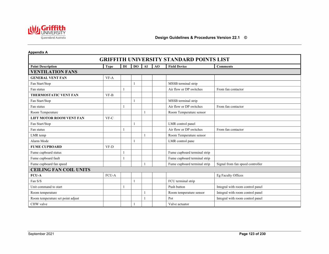
Design Guidelines & Procedures Version 22.1 ©
September 2021 Page 123 of 230
Appendix A
GRIFFITH UNIVERSITY STANDARD POINTS LIST Point Description Type DI DO AI AO Field Device Comments
VENTILATION FANS GENERAL VENT FAN VF-A
Fan Start/Stop 1 MSSB terminal strip
Fan status 1 Air flow or DP switches From fan contactor
THERMOSTATIC VENT FAN VF-B
Fan Start/Stop 1 MSSB terminal strip
Fan status 1 Air flow or DP switches From fan contactor
Room Temperature 1 Room Temperature sensor
LIFT MOTOR ROOM VENT FAN VF-C
Fan Start/Stop 1 LMR control panel
Fan status 1 Air flow or DP switches From fan contactor
LMR temp 1 Room Temperature sensor
Alarm Mode 1 LMR control pane
FUME CUPBOARD VF-D
Fume cupboard status 1 Fume cupboard terminal strip
Fume cupboard fault 1 Fume cupboard terminal strip
Fume cupboard fan speed 1 Fume cupboard terminal strip Signal from fan speed controller
CEILING FAN COIL UNITS FCU-A FCU-A Eg Faculty Offices
Fan S/S 1 FCU terminal strip
Unit command to start 1 Push button Integral with room control panel
Room temperature 1 Room temperature sensor Integral with room control panel
Room temperature set point adjust 1 Pot Integral with room control panel
CHW valve 1 Valve actuator
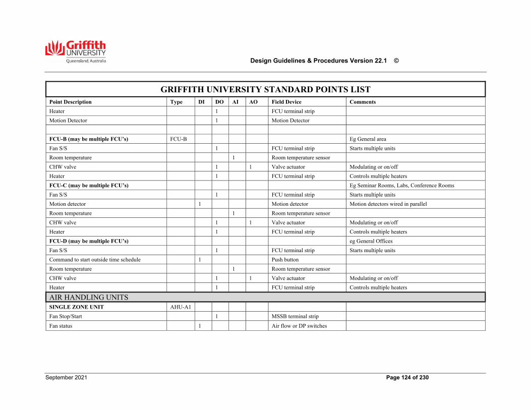
Design Guidelines & Procedures Version 22.1 ©
September 2021 Page 124 of 230
GRIFFITH UNIVERSITY STANDARD POINTS LIST
Point Description Type DI DO AI AO Field Device Comments
Heater 1 FCU terminal strip
Motion Detector 1 Motion Detector
FCU-B (may be multiple FCU’s) FCU-B Eg General area
Fan S/S 1 FCU terminal strip Starts multiple units
Room temperature 1 Room temperature sensor
CHW valve 1 1 Valve actuator Modulating or on/off
Heater 1 FCU terminal strip Controls multiple heaters
FCU-C (may be multiple FCU’s) Eg Seminar Rooms, Labs, Conference Rooms
Fan S/S 1 FCU terminal strip Starts multiple units
Motion detector 1 Motion detector Motion detectors wired in parallel
Room temperature 1 Room temperature sensor
CHW valve 1 1 Valve actuator Modulating or on/off
Heater 1 FCU terminal strip Controls multiple heaters
FCU-D (may be multiple FCU’s) eg General Offices
Fan S/S 1 FCU terminal strip Starts multiple units
Command to start outside time schedule 1 Push button
Room temperature 1 Room temperature sensor
CHW valve 1 1 Valve actuator Modulating or on/off
Heater 1 FCU terminal strip Controls multiple heaters
AIR HANDLING UNITS SINGLE ZONE UNIT AHU-A1
Fan Stop/Start 1 MSSB terminal strip
Fan status 1 Air flow or DP switches
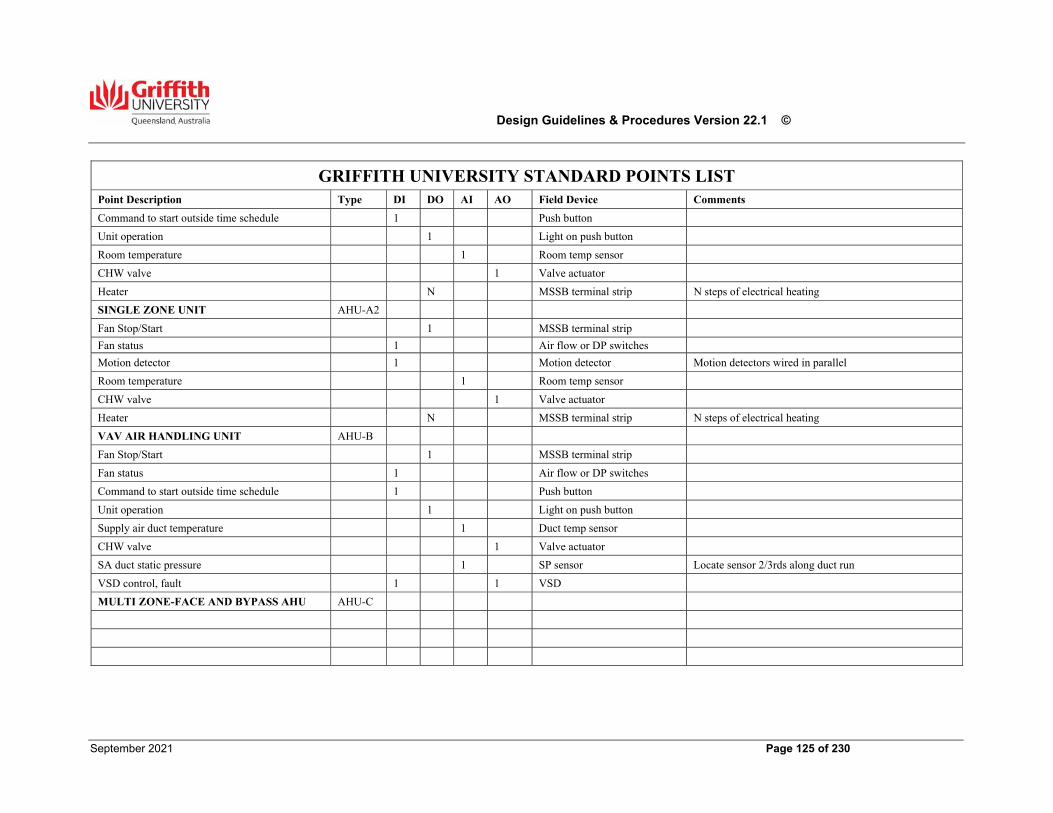
Design Guidelines & Procedures Version 22.1 ©
September 2021 Page 125 of 230
GRIFFITH UNIVERSITY STANDARD POINTS LIST
Point Description Type DI DO AI AO Field Device Comments
Command to start outside time schedule 1 Push button
Unit operation 1 Light on push button
Room temperature 1 Room temp sensor
CHW valve 1 Valve actuator
Heater N MSSB terminal strip N steps of electrical heating
SINGLE ZONE UNIT AHU-A2
Fan Stop/Start 1 MSSB terminal strip
Fan status 1 Air flow or DP switches
Motion detector 1 Motion detector Motion detectors wired in parallel
Room temperature 1 Room temp sensor
CHW valve 1 Valve actuator
Heater N MSSB terminal strip N steps of electrical heating
VAV AIR HANDLING UNIT AHU-B
Fan Stop/Start 1 MSSB terminal strip
Fan status 1 Air flow or DP switches
Command to start outside time schedule 1 Push button
Unit operation 1 Light on push button
Supply air duct temperature 1 Duct temp sensor
CHW valve 1 Valve actuator
SA duct static pressure 1 SP sensor Locate sensor 2/3rds along duct run
VSD control, fault 1 1 VSD
MULTI ZONE-FACE AND BYPASS AHU AHU-C
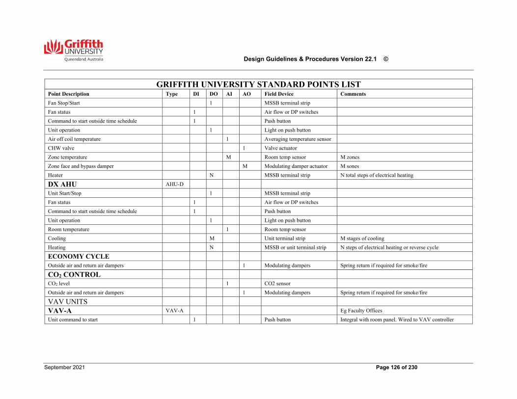
Design Guidelines & Procedures Version 22.1 ©
September 2021 Page 126 of 230
GRIFFITH UNIVERSITY STANDARD POINTS LIST
Point Description Type DI DO AI AO Field Device Comments
Fan Stop/Start 1 MSSB terminal strip
Fan status 1 Air flow or DP switches
Command to start outside time schedule 1 Push button
Unit operation 1 Light on push button
Air off coil temperature 1 Averaging temperature sensor
CHW valve 1 Valve actuator
Zone temperature M Room temp sensor M zones
Zone face and bypass damper M Modulating damper actuator M sones
Heater N MSSB terminal strip N total steps of electrical heating
DX AHU AHU-D
Unit Start/Stop 1 MSSB terminal strip
Fan status 1 Air flow or DP switches
Command to start outside time schedule 1 Push button
Unit operation 1 Light on push button
Room temperature 1 Room temp sensor
Cooling M Unit terminal strip M stages of cooling
Heating N MSSB or unit terminal strip N steps of electrical heating or reverse cycle
ECONOMY CYCLE
Outside air and return air dampers 1 Modulating dampers Spring return if required for smoke/fire
CO2 CONTROL
CO2 level 1 CO2 sensor
Outside air and return air dampers 1 Modulating dampers Spring return if required for smoke/fire
VAV UNITS
VAV-A VAV-A Eg Faculty Offices
Unit command to start 1 Push button Integral with room panel. Wired to VAV controller
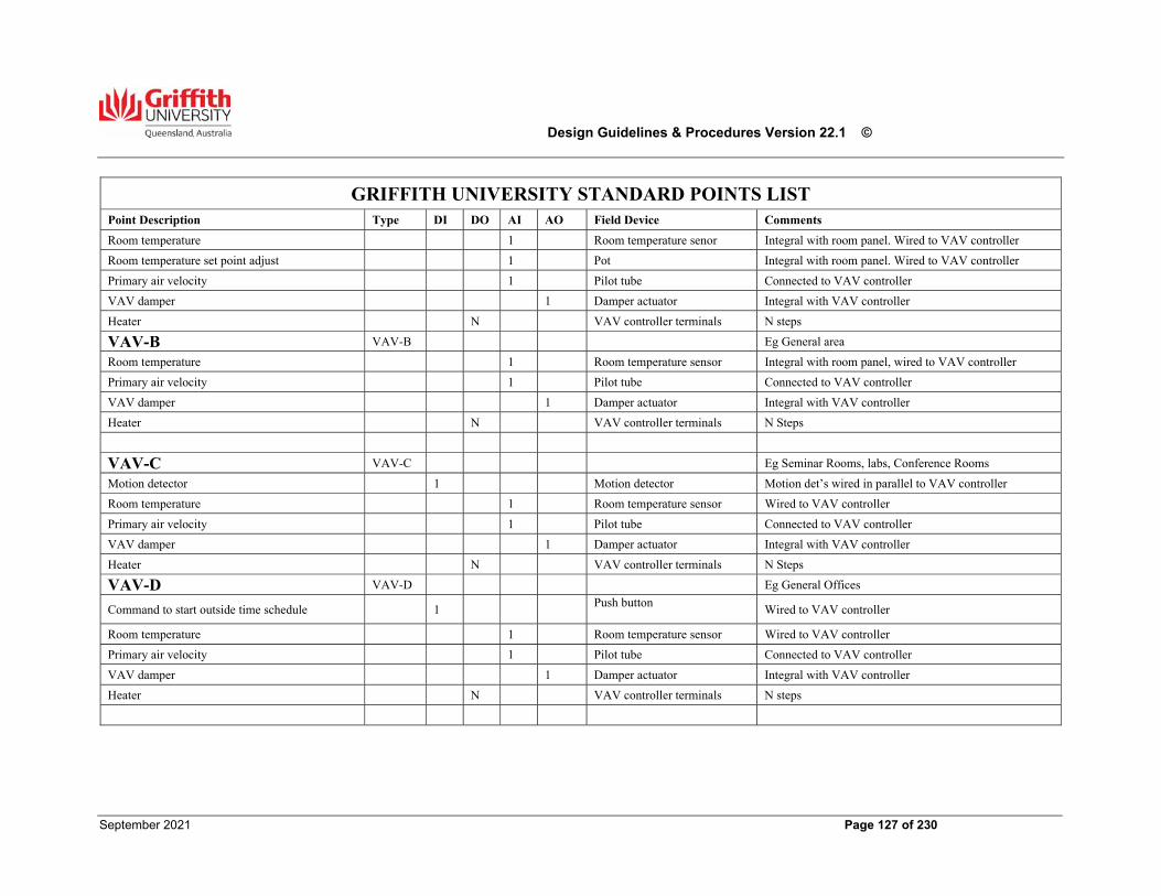
Design Guidelines & Procedures Version 22.1 ©
September 2021 Page 127 of 230
GRIFFITH UNIVERSITY STANDARD POINTS LIST
Point Description Type DI DO AI AO Field Device Comments
Room temperature 1 Room temperature senor Integral with room panel. Wired to VAV controller
Room temperature set point adjust 1 Pot Integral with room panel. Wired to VAV controller
Primary air velocity 1 Pilot tube Connected to VAV controller
VAV damper 1 Damper actuator Integral with VAV controller
Heater N VAV controller terminals N steps
VAV-B VAV-B Eg General area
Room temperature 1 Room temperature sensor Integral with room panel, wired to VAV controller
Primary air velocity 1 Pilot tube Connected to VAV controller
VAV damper 1 Damper actuator Integral with VAV controller
Heater N VAV controller terminals N Steps
VAV-C VAV-C Eg Seminar Rooms, labs, Conference Rooms
Motion detector 1 Motion detector Motion det’s wired in parallel to VAV controller
Room temperature 1 Room temperature sensor Wired to VAV controller
Primary air velocity 1 Pilot tube Connected to VAV controller
VAV damper 1 Damper actuator Integral with VAV controller
Heater N VAV controller terminals N Steps
VAV-D VAV-D Eg General Offices
Command to start outside time schedule 1 Push button
Wired to VAV controller
Room temperature 1 Room temperature sensor Wired to VAV controller
Primary air velocity 1 Pilot tube Connected to VAV controller
VAV damper 1 Damper actuator Integral with VAV controller
Heater N VAV controller terminals N steps
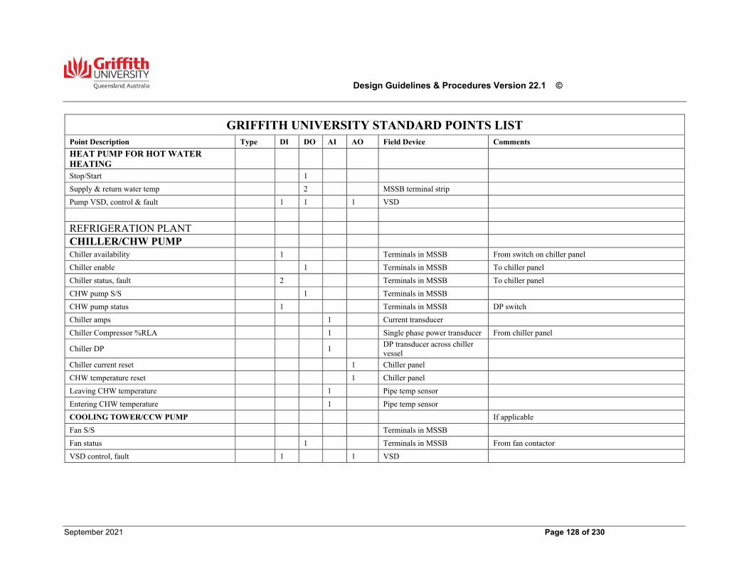
Design Guidelines & Procedures Version 22.1 ©
September 2021 Page 128 of 230
GRIFFITH UNIVERSITY STANDARD POINTS LIST
Point Description Type DI DO AI AO Field Device Comments
HEAT PUMP FOR HOT WATER HEATING
Stop/Start 1
Supply & return water temp 2 MSSB terminal strip
Pump VSD, control & fault 1 1 1 VSD
REFRIGERATION PLANT
CHILLER/CHW PUMP
Chiller availability 1 Terminals in MSSB From switch on chiller panel
Chiller enable 1 Terminals in MSSB To chiller panel
Chiller status, fault 2 Terminals in MSSB To chiller panel
CHW pump S/S 1 Terminals in MSSB
CHW pump status 1 Terminals in MSSB DP switch
Chiller amps 1 Current transducer
Chiller Compressor %RLA 1 Single phase power transducer From chiller panel
Chiller DP 1 DP transducer across chiller vessel
Chiller current reset 1 Chiller panel
CHW temperature reset 1 Chiller panel
Leaving CHW temperature 1 Pipe temp sensor
Entering CHW temperature 1 Pipe temp sensor
COOLING TOWER/CCW PUMP If applicable
Fan S/S Terminals in MSSB
Fan status 1 Terminals in MSSB From fan contactor
VSD control, fault 1 1 VSD
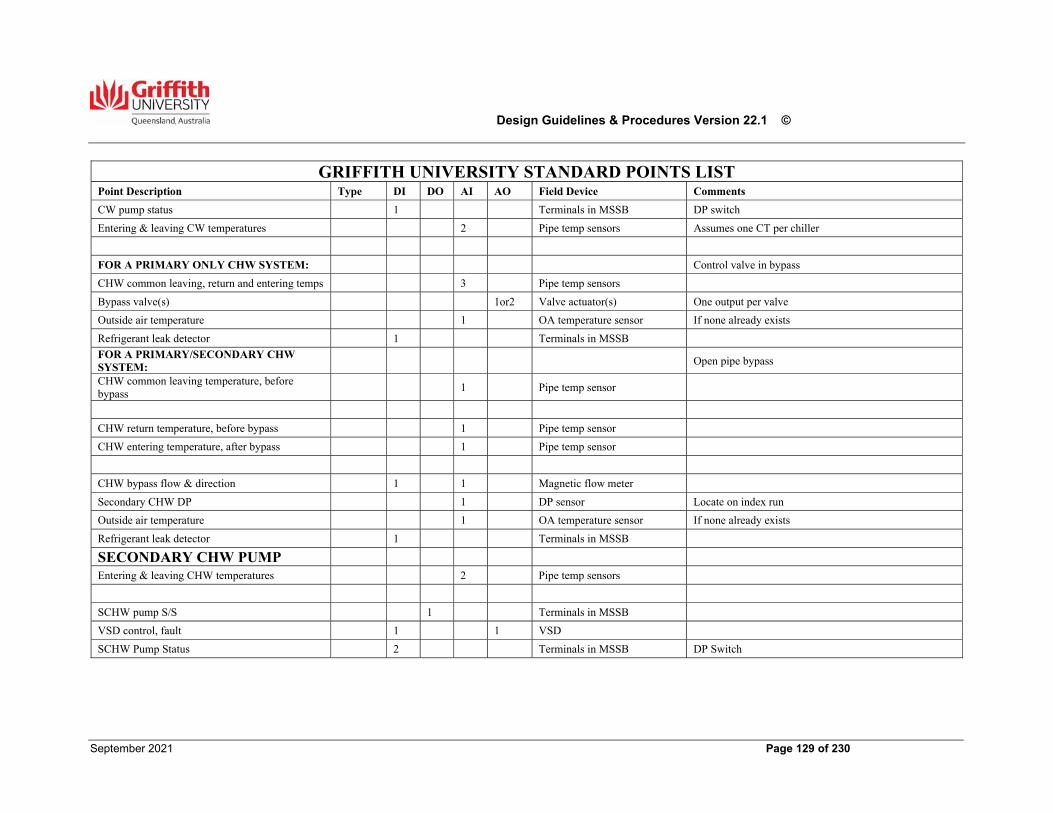
Design Guidelines & Procedures Version 22.1 ©
September 2021 Page 129 of 230
GRIFFITH UNIVERSITY STANDARD POINTS LIST
Point Description Type DI DO AI AO Field Device Comments
CW pump status 1 Terminals in MSSB DP switch
Entering & leaving CW temperatures 2 Pipe temp sensors Assumes one CT per chiller
FOR A PRIMARY ONLY CHW SYSTEM: Control valve in bypass
CHW common leaving, return and entering temps 3 Pipe temp sensors
Bypass valve(s) 1or2 Valve actuator(s) One output per valve
Outside air temperature 1 OA temperature sensor If none already exists
Refrigerant leak detector 1 Terminals in MSSB
FOR A PRIMARY/SECONDARY CHW SYSTEM:
Open pipe bypass
CHW common leaving temperature, before bypass
1 Pipe temp sensor
CHW return temperature, before bypass 1 Pipe temp sensor
CHW entering temperature, after bypass 1 Pipe temp sensor
CHW bypass flow & direction 1 1 Magnetic flow meter
Secondary CHW DP 1 DP sensor Locate on index run
Outside air temperature 1 OA temperature sensor If none already exists
Refrigerant leak detector 1 Terminals in MSSB
SECONDARY CHW PUMP
Entering & leaving CHW temperatures 2 Pipe temp sensors
SCHW pump S/S 1 Terminals in MSSB
VSD control, fault 1 1 VSD
SCHW Pump Status 2 Terminals in MSSB DP Switch
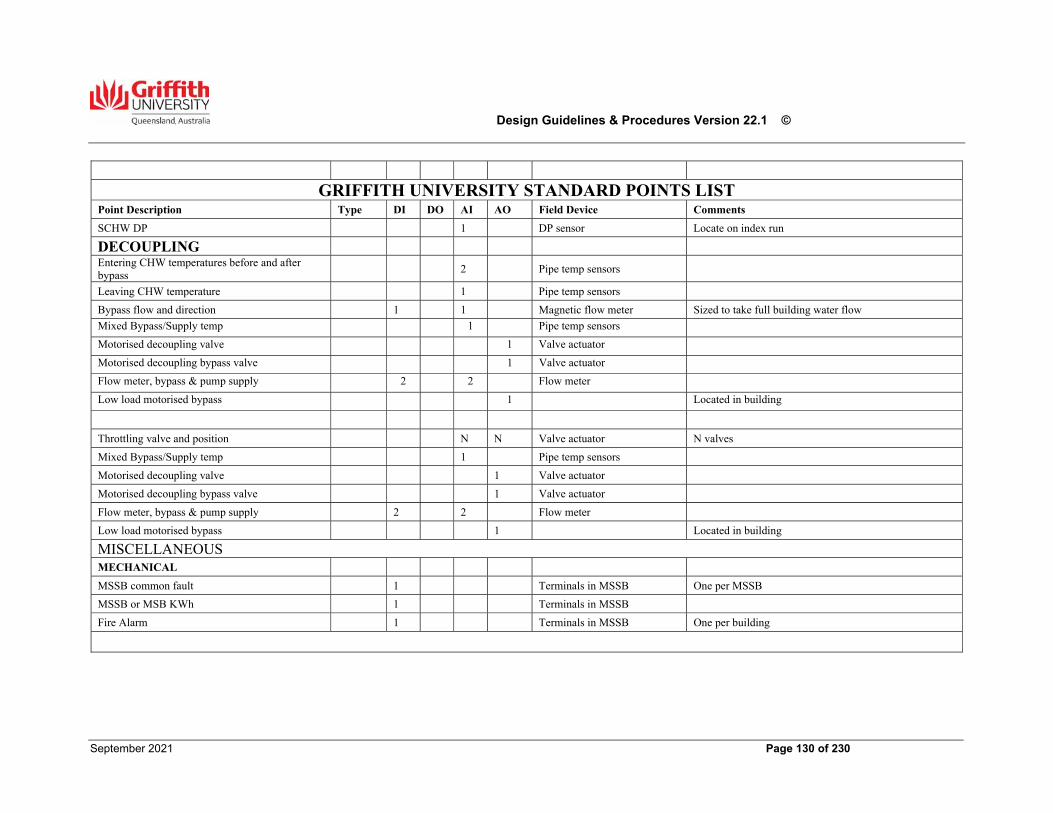
Design Guidelines & Procedures Version 22.1 ©
September 2021 Page 130 of 230
GRIFFITH UNIVERSITY STANDARD POINTS LIST
Point Description Type DI DO AI AO Field Device Comments
SCHW DP 1 DP sensor Locate on index run
DECOUPLING
Entering CHW temperatures before and after bypass
2 Pipe temp sensors
Leaving CHW temperature 1 Pipe temp sensors
Bypass flow and direction 1 1 Magnetic flow meter Sized to take full building water flow
Mixed Bypass/Supply temp 1 Pipe temp sensors
Motorised decoupling valve 1 Valve actuator
Motorised decoupling bypass valve 1 Valve actuator
Flow meter, bypass & pump supply 2 2 Flow meter
Low load motorised bypass 1 Located in building
Throttling valve and position N N Valve actuator N valves
Mixed Bypass/Supply temp 1 Pipe temp sensors
Motorised decoupling valve 1 Valve actuator
Motorised decoupling bypass valve 1 Valve actuator
Flow meter, bypass & pump supply 2 2 Flow meter
Low load motorised bypass 1 Located in building
MISCELLANEOUS
MECHANICAL
MSSB common fault 1 Terminals in MSSB One per MSSB
MSSB or MSB KWh 1 Terminals in MSSB
Fire Alarm 1 Terminals in MSSB One per building
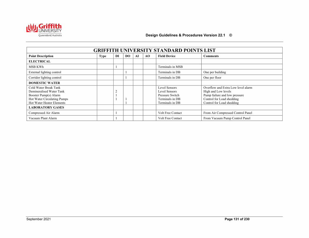
Design Guidelines & Procedures Version 22.1 ©
September 2021 Page 131 of 230
GRIFFITH UNIVERSITY STANDARD POINTS LIST
Point Description Type DI DO AI AO Field Device Comments
ELECTRICAL
MSB KWh 1 Terminals in MSB
External lighting control 1 Terminals in DB One per building
Corridor lighting control 1 Terminals in DB One per floor
DOMESTIC WATER
Cold Water Break Tank Demineralised Water Tank Booster Pump(s) Alarm Hot Water Circulating Pumps Hot Water Heater Elements
2 1 1
1 1
Level Sensors Level Sensors Pressure Switch Terminals in DB Terminals in DB
Overflow and Extra Low level alarm High and Low levels Pump failure and low pressure Control for Load shedding Control for Load shedding
LABORATORY GASES
Compressed Air Alarm 1 Volt Free Contact From Air Compressed Control Panel
Vacuum Plant Alarm 1 Volt Free Contact From Vacuum Pump Control Panel
Design Guidelines & Procedures Version 22.1 ©
September 2021 Page 132 of 230
19.00 Fire Services The requirements of this Section are Mandatory.
Generally This Section outlines GU's minimum requirements for the following Fire Detection Systems and Passive Fire Protection;
Automatic Fire Detection and Alarm Systems. Emergency Warning and Intercommunications Systems (EWIS) Emergency warning Systems (EWS) Hydrants and hose reels. First Attack Fire Fighting Equipment (Extinguishers & Blankets) Fire Hazard Indices
Each building shall be provided with a system of fire protection in accordance with the relevant Codes and Standards. In general, all buildings shall be equipped with Automatic Fire Detection & Alarm Systems connected to the Building’s Fire Indicator Panel (FIP). The building FIP shall be connected to the Site Master Panel and Site Mimic Panel(s) and the Qld Fire & Rescue Service (QFES), or as otherwise agreed to by the QFES.
Basic Requirements for Fire Detection & Alarm Systems All fire detection and alarm systems shall be arranged so that in the event of an alarm condition existing in any protected zone, including the operation of a manual push button alarm, the systems shall provide, but not be limited to, the following functions;
Illuminate an indicator light for the relevant circuit on the building fire indicator panel. Illuminate an indicator light for the building on the Master Panel. Transmit an alarm signal to the QFES, via a site Mimic Panel. Energise alarms. Shut down any integrated ventilation systems, operate smoke doors, fire doors, emergency exit doors, fire dampers, smoke exhaust systems, make up air facilities, stair pressurisation
systems and flammable gas services. Transmit a signal to the Pager Alert System (where installed) to activate the Pager System. Provide a signal to visual alarms. Transmit signal to operate electronic door locks.
The fire alarm system shall also incorporate an emergency warning and communication system to AS 1670-1 and AS 2220-1. Fire detection and alarm systems shall comply with the Fire & Rescue Service Act 1990 Sections 104D and 104DA, and the ‘Fire Alarm and Building Design Guidelines for the Reduction of Unwanted Alarms’ issued by the QFES.
Fire Services Contractor Qualifications Fire Services Contractors shall provide evidence that they are duly registered with the Fire Protection Contractors Registration Board of Queensland, and have such licences as required by State legislation, before commencing any installations.
General Equipment Requirements All equipment associated with Fire Alarms, EWIS and EWS shall be provided by a recognised Fire Alarm company or Manufacturer with a proven record of high standard within the Fire Protection Industry for a period of not less than 10 years. Installation of such equipment shall not be regarded as complying with this Section unless it is carried out by the manufacturer of the equipment, or by a Contractor duly authorised by the manufacturer.
Design Guidelines & Procedures Version 22.1 ©
September 2021 Page 133 of 230
Fire Indicator Panels (FIP) Each building shall be equipped with a FIP showing all alarm circuits. Each FIP shall have a minimum provision of 10% spare space to allow for future circuit installation. The maximum number of thermal alarms or smoke detectors that shall be provided on any circuit shall be no greater than 90% as permitted by the Code. FIPs shall be auto testing and equipped with additional ‘LED’ indication for ease of circuit identification. FIPs shall be fitted with a Check Alarm facility which shall be activated on commissioning of the panel. All new FIPs for buildings on each of the GU campuses shall be as follows;
Gold Coast, South Bank & Logan – ‘Ampac’ manufactured panels Nathan & Mt Gravatt – A proprietary manufactured panel (e.g. Inertia)
Where an addressable panel is installed as a ‘Site Master Panel’ or a ‘Building Panel’, a factory fitted strip type printer shall be integrated into the panel. The panel manufacturer shall provide to CLF at no additional cost all maintenance tools and software for the servicing and upgrading of the panels. All integrated evacuation systems shall be factory fitted. Electronic door locking output shall not be connected to any auxiliary output controlled by the fire panel door switch. The Building FIP shall be Non Latching. Alterations or additions to existing fire panels shall only be carried out by the GU Fire Equipment Maintenance Contractor. Work by any other contractor is not permitted. A full impact study of the existing system shall be conducted for any alterations or additions and must be approved by the Superintendent. Installation cabling from any Building FIP to the Site Master Panel FIP and Site MIMIC Panel(s) shall be connected by the GU Fire Equipment Maintenance Contractor. Sufficient cabling and information is to be made available for this connection. All cabling to and from FIP’s shall be continuous and without joints. The Site Mimic Panel shall be upgraded to show all new buildings installed under the contract. ‘Schematic Location’ diagrams associated with FIP’s shall be colour coded and of such design and contain such information as approved by the SUPERINTENDENT. They shall be of plastic, be ‘Back Engraved’ and show all relevant information. Each FIP shall also be linked via a BMS control in the building to indicate an alarm on the BMS. All FIPs, and Mimic Panels shall be positioned as outlined in AS 1670 - Control and Indicating Equipment. FIPs shall not be positioned on external walls or in sun affected locations. Lightning surge protection shall be installed to all FIPs. A spring return Fire Service Isolation button shall be fitted to the building FIP for testing purposes.
Detection Systems Buildings shall be fitted with thermal and/or smoke detectors in accordance with the requirements of AS 1670 - Automatic Fire Alarms, and be interfaced with visual detectors such as flashing strobe lights to be installed in public areas and rooms with high acoustic isolation. Detectors shall be ‘Hocheki’ type in accordance with the requirements of AS 1603.
Design Guidelines & Procedures Version 22.1 ©
September 2021 Page 134 of 230
Thermal detectors shall be of the electro-pneumatic, compensating rate of rise type. Thermo-pile and solid state alarms are also acceptable. Smoke detectors (combustion type) are to be used where early warning is required in areas such as sub-stations, switch rooms, PABX and MDF rooms, TER rooms and other areas as required by Australian Standards or other Codes. Thermal detection shall be used in other areas approved by the Superintendent and the QFES. Ceiling mounted detectors shall be mounted in accordance with the requirements of Section 14.00 Ceilings. Detectors are not to be positioned directly above transformers or other electrically energised equipment. ‘VESDA’ systems shall be installed in areas where nominated in the SDFs. All thermal and smoke detectors shall have ‘L.E.D.’ indication. Concealed detectors in areas such as ducts, DB’s, lift motor rooms and other small rooms, shall have the remote indicator mounted on the wall over the door. Note - Remote indication is only required for conventional flip panel installations. Concealed space detectors shall be equipped with remote neon indicators labelled with the type and location of the detector. Concealed detectors should be grouped in the same manner as room detectors and not be installed on a complete circuit extending over the entire floor. Alarm zones shall be arranged to suit the attending Fire Service and the Superintendent. All detectors shall be identified by labels fixed to the base, identifying the circuit and detector number corresponding to the numbering plan on the as installed drawings and ’Schematic Zone’ diagram. Large rooms/area may be deemed to require Remote Detector indicators for Fire Service advice. Such specific rooms/areas requiring remote indicators shall be determined by Building Surveyor and/or the Superintendent. On recent projects, the QRFS has required the installation of thermal detectors not smoke detectors in laboratories and kitchenettes. Prior to designing the detection system in any such spaces, the Fire Services Consultant shall consult with and confirm the requirements of the QRFS.
Visual Alarm Indicators All new buildings or any upgrade of an existing building shall have an emergency warning system installed with visual alarm indicators in accordance with AS 1603.11, comprising dual AMBER and RED flashing lights. The AMBER light shall be programmed to flash on an ‘Alert’ alarm, and the RED light will be programmed to flash on an ‘Evacuate’ alarm.
Fire Services Wiring All fire alarm wiring between floors shall be run in a separate, accessible cable tray or metal duct. Trays and the duct shall be painted RED in colour where exposed or colour banded where concealed. Fire Alarm cables shall not run on the same cable trays as electrically energised cables or be installed in Electrical or Data cable risers. Refer to Section 20.00 Electrical Services for wiring in ceiling spaces and riser ducts.
Hydraulic Fire Services
Water Supply
The water supply for hydrants and hose reels shall be provided via a separate dedicated water service to the building. The appropriate backflow and isolation valves shall be located in the Valve Room.
Design Guidelines & Procedures Version 22.1 ©
September 2021 Page 135 of 230
Pipe Materials Mains and fittings buried in the ground shall be:
PE100 ‘red” striped SDR 11 PN16 minimum to AS4130. Mains and fittings above ground shall be:
Galvanized steel medium duty, Victaulic system with EZ style 009H installation ready couplings or approved equal.
Hydrants including signage and block plans shall be provided in accordance AS 2419.1. Unless otherwise specified, hydrant systems shall be a’ wet pipe’ system. System designs, hydraulic calculations and variations shall be submitted and agreed to with CLF prior to installation. Hydrant booster installations where required shall meet the requirements of AS 2419.1/2/3. The location, colour and design of fire booster installations shall be approved by the Building Surveyor and the QFES prior to design finalisation. The design of the enclosure must be approved by OFM. Masonry construction is preferred to metal cabinets. Any inground spring type hydrants shall be of the A.W.E. (Associated Water Equipment) ‘Maxi Flow’ nylon coated type. Where internal hydrants are installed, a safe discharge point shall be provided for the testing of the most disadvantaged fire hydrants. The discharge point shall be fitted with a 65mm round QRFS thread coupling and shall discharge to the Stormwater drainage system. The discharge pipework shall be braced and supported to the approval of the Superintendent.
Hydrants Hydrants including signage and block plans shall be provided in accordance AS 2419.1. Block plan signage to include the following additional information: -
BCA Building classifications Relevant Australian Standard including version date National Construction Code version including version date Most disadvantaged hydrant/s location/description Dangerous Goods locations and main switch boards Design frictional loss through system in KPA
Unless otherwise specified, hydrant systems shall be a’ wet pipe’ system. System designs, hydraulic calculations and variations shall be submitted and agreed to with CLF prior to installation. Hydrant booster installations where required shall meet the requirements of AS 2419.1/2/3. The location, colour and design of fire booster installations shall be approved by the Building Surveyor and the QFES prior to design finalisation. The design of the enclosure must be approved by Facilities Management. Masonry construction is preferred to metal cabinets. Any inground spring type hydrants shall be of the A.W.E. (Associated Water Equipment) ‘Maxi Flow’ nylon coated type. Where internal hydrants are installed, a safe discharge point shall be provided for the testing of the most disadvantaged fire hydrants. The discharge point shall be fitted with a 65mm round QRFS thread coupling and shall discharge to the Stormwater drainage system.
Design Guidelines & Procedures Version 22.1 ©
September 2021 Page 136 of 230
The discharge pipework shall be of Galvanised medium steel construction within the above ground building envelope and shall be braced and supported to the approval of GU Engineering Services. Fire hose reels shall be provided to serve all buildings and shall be of ‘Wormald’ manufacture, or an alternative approved by the SUPERINTENDENT. Installation of the hose reel system shall comply with Part E2 of the BCA.
Hose Reels Fire hose reels shall be provided to serve all buildings and shall be of ‘Wormald’ manufacture, or an alternative approved by GU Engineering Services. Installation of the hose reel system shall comply with Part E1 of the BCA and AS 2441. All External fire hose reel to be installed in a lockable “003” QFES keyed enclosure with a break glass key window.
Fire Hydrant and Hose Reel Travel Paths Fire hydrant and hose reel travel paths are to be clearly identified for all buildings on a dedicated drawing in the required GU drafting format.
Fire Sprinklers
A fire sprinkler system shall be provided where required in accordance with Spec E1.5 of the BCA and AS 2118.4.
Testing Water supply pipelines for Fire Mains and Services shall be tested at 2.1 Mpa for twelve (12) hours and generally kept charged thereafter. Fire Hydrants and Hose Reels shall be tested for pressure and flow as required by the BCA and QFES. Such tests to be certified by the responsible design consultant. First Attack Fire Fighting Equipment.
Fire Extinguishers
Fire extinguishers shall be provided to all areas in accordance with the BCA. Only extinguishers approved by SA are acceptable. In general, the following extinguishers should be used for standardisation and shall be provided under the Contract:
General Office areas
(where Hose Reels are not installed)
Air Water 9 litre
Cooking areas (commercial) Wet Chemical
CO2
7.5 litre
3.5 kg
High electrical hazard – main switchboard Dry Powder 2.5 kg
Plant Rooms Dry Powder 4.5 kg
Laboratories
(adjacent each Fire Hose Reel or in designated “Fire Cabinets”)
Dry Powder
4.5 kg
Fume Cupboards Dry Powder 2.5 kg of 5b rating
Design Guidelines & Procedures Version 22.1 ©
September 2021 Page 137 of 230
Extinguishers should be used where the risk so demands. All extinguishers shall be provided with coded location signs and usage signs in accordance with the requirements of AS 1851. Extinguishers shall be installed in accordance with the requirements of Australian Standard 2444 and at a height agreed with the Superintendent.
Fire Blankets
Fire blankets shall be installed in all commercial kitchen areas and in laboratories. Locations shall be approved by the Superintendent.
Special Fire Systems Where required by Legislation or other reasons, provide special systems such as;
Gas extinguishment systems High velocity water spray systems High expansion foam systems Sprinklers
Any proposal for any of the above systems should be discussed with CLF prior to documentation.
Door Hold Open Devices The requirements for hold open devices activated by the fire alarm systems are outlined in Section 11.00 Doors & Hardware. Hold open devices on Smoke or Fire doors shall not be of the ‘Combination hold open/Auto door closer’ type. The hold open devices shall be wall mounted at 1800mm above finished floor level, and any variation to this height shall be at the discretion of the Superintendent. The hold open devices shall be of a type, manufacture, configuration and design as agreed to by the Superintendent if they are an alternative to those nominated in Section 11.00. Electro magnetic hold open devices (EMHODs) shall be provided on all fire doors in fire isolated stairwells used for occupant circulation.
Door Control Any doors secured by electric locks must be interfaced with the fire alarm system as outlined previously in this Section. Refer to Section 11.00 for details of electric lock types.
Smoke Exhaust Systems Any smoke exhaust systems incorporated into the building design shall be in accordance with the BCA and the relevant Australian Standards.
Fume Cupboards Fire protection measures for Fume Cupboards shall comply with AS 2243-8 and with AS 3689-1 for Specialised Protection.
Fire Hazard Indices Commonwealth Fire Board Fire Safety Circular 73 ‘Linings for Buildings’ including Early Fire Hazard Indices shall be used as a guide to determine acceptable materials for use in buildings. Fire Hazard Indices information shall be provided to the Superintendent during the design stage.
Design Guidelines & Procedures Version 22.1 ©
September 2021 Page 138 of 230
Hazchem Signage Appropriate signage shall be determined and installed in all areas deemed to require such signage on the completion of all new buildings and refurbishments.
Emergency Services Vehicle Access Access requirements for Fire Services vehicles shall be designed to accommodate the largest vehicle in service of the normally attending Fire Service. Dimensions of vehicles should be obtained from the Motor Officer or other nominated Officer of the QRFS, or from either the Superintendent or Superintendent. Access requirements shall be determined at the schematic stage of design and submitted for review to the Building Surveyor and the QFES. Safe vehicle access must be considered including fire separation distances and space for vehicle turn around during an emergency event.
Inspections & Documentation Pre-Approval Inspections - Building Fire Safety Systems shall be fully tested to the approval of the Superintendent prior to final approval inspections being carried out by QFES Community Safety Officers. Inspections During Construction – The Certifier and Superintendent, and the relevant QFES Officers shall be notified before completion and prior to covering up any Special Fire Services to allow any required inspections to be carried out. Final Inspections - Authority for final inspections by QFES Community Safety Officers shall be the responsibility of the Building Certifier and/or the Superintendent. Documentation - The following documentation shall be available at the time of both inspections as required by QFES;
Installation certificates (fire alarm systems, hydraulics, smoke control, etc). Test certificates for installed systems. Draft/Final Fire Alarm Zone schematic diagram. Draft/Final system ‘Block Plan’ (if applicable)
All Draft documentation must be provided for review by the Superintendent in advance of the Pre-Approval inspections.
Design Guidelines & Procedures Version 22.1 ©
September 2021 Page 139 of 230
20.00 Electrical Services
The requirements of this Section are generally Mandatory (Refer to Section 1.00)
This Section outlines Griffith University's specific requirements for electrical services. Comply with all relevant Australian Standards and the National Construction Code.
Demolition The Contractor, in conjunction with campus maintenance staff, must identify and label all cables, equipment, boards and accessories which are to remain and which are redundant prior to the commencement of demolition. All redundant electrical services including cables, equipment, switch boards, light fittings and accessories shall be removed in their entirety from the site and the ‘as constructed’ record amended accordingly. Offer removed items to GU prior to disposal.
External Lighting
External lighting design shall comply with AS 1158. When using selection criteria tables to determine the applicable lighting subcategory, the minimum risk/selection criteria is assumed to be ‘Medium’. Confirm with GU if the selection criteria for the areas under consideration are considered ‘High’. Illumination levels, luminaire types and control strategy for each area shall be nominated by the designer and submitted for approval as part of Schematic Design. All external lighting shall be LED luminaires with 3000K colour temperature, unless specified otherwise to serve a specific purpose. The lighting design must consider the high glare of LED luminaires and must not cause any discomfort glare. Carpark, pathway and street lighting luminaires shall be WE-EF VFL or an approved equal. Minimise the number of luminaire types and standardise types as much as possible. All pole top mounted luminaires must have a ‘quick release’ feature for ease of replacement. Bollards are generally unacceptable. If the project scope includes a new path or road, the project scope shall include the lighting of that path or road. Where paths run adjacent to, through or beneath buildings, the luminaire shall be mounted on the external wall of the building and the mounting location must be easily accessible for future maintenance work via an elevated work platform. Lighting poles shall be fitted with base plates and mounted on concrete footing with cast-in cage and bolts complete with levelling nuts and washers. After erection, bolts shall be trimmed and capped to a maximum of 10mm above the lock nut. Poles must be installed with the base plate above the finished level of pavements or garden beds. Poles with bases buried in footings are unacceptable. A traffolyte label must be strapped to the pole’s incoming cable at a visible location to indicate the supply origin i.e. distribution board reference and the building it is fed from. Install RCDs on street lighting circuits. Reticulate cabling to all lighting poles on a loop-in/loop-out basis. All lighting poles shall have terminals, a circuit breaker and surge protection located in the base (alternatively, surge protection may be integrated into the luminaire power supply), accessible through a removable panel. Provide DIN rail within the base of the pole for mounting. Hinged poles must be used where the pole height is greater than 3 metres and there is no access for an EWP or ‘cherry picker’, or there is no flat surface to utilise a work platform. External lighting shall be served by two separate circuits, one for general external lighting and one for feature lighting. Both circuits must be controlled by BMS lighting control signals for time scheduling and provided with an Auto Manual Off (AOM) switch for isolation/override. External lighting for specialist areas such as study pods, can be controlled by a timed weather proof push button located on the luminaire support post provided that there is sufficient lighting to maintain safe movement and security without this lighting.
Design Guidelines & Procedures Version 22.1 ©
September 2021 Page 140 of 230
All external luminaires selected must have a minimum ten year replacement warranty, commencing at practical completion. Where a substitute is offered by a Contractor during the construction phase to replace any specified electrical product, the Contractor is to provide a comprehensive engineering assessment/report to demonstrate that the proposed product is equal or better than the specified product. This document must include assessment of all engineering aspects including but not limited to comparison of the following:
Registration of compliance mark (RCM) in Australia, LM80, LM79 and TM21 NATA certified test certificates, ERAC registration documentation, and EMC compliance documentation Full lighting design Working sample of every type of fitting
The engineering assessment/report must be provided at a timely manner and at no cost to GU.
Internal Lighting
Internal areas shall be designed in accordance with the minimum requirements of AS 1680 and AS 1428. Provide higher illumination levels or other additions to the lighting system where nominated by users in the SDFs. Illumination levels, luminaire types and control strategy for each area shall be nominated by the designer and submitted for approval as part of Schematic Design. Luminaires manufactured in Australia, comprising Australian-made components and/or assembled in Australia are preferred. LED luminaires shall be used for all lighting. All specified internal LED fittings shall have the following characteristics:
a CRI >8.3, R9 value > 7 Gamut Index > 8 SDCM value < 3 Glare index <19
Minimise the number of luminaire types and standardise as much as possible. All internal luminaires shall be neutral white (4000K) unless stated otherwise in the Space Description Forms, or to suit specific functions. All luminaires shall be installed at a maximum of 3000 mm AFFL. Installation shall provide easy access for maintenance. Do not install luminaires over voids or stairs. In lecture theatres and auditoria with high ceilings, mount lighting on a lowerable lighting beam system. Lighting beams shall have a local, key lockable control to raise and lower the beam. In T-bar ceiling grids, install 1200x300 LED white recessed troffer luminaires. Consider specifying a fitting with a lumen output of either 1500lm or 2700lm. In teaching spaces, provide luminaires to illuminate the whiteboard. Use an asymmetric distribution and carefully select and position luminaires to minimise reflections and glare. In lecture theatres, provide low level theatre-style aisle and stair lighting to illuminate walkways while in presentation mode. Aisle stairs and ramps within lecture theatres and the like shall have lighting mounted on the end of the seating rows or fixed writing benches. Luminaires shall have number inserts. The luminaire should be selected to avoid discomfort glare. Illuminate the teaching position in lecture theatres with dedicated spotlight/s. Avoid lighting from other luminaire groups spilling onto projection surfaces. Illuminated LED ‘Theatre in Use‘ signs must be provided adjacent to all entry doors to lecture theatres which seat 100 or more persons.
Design Guidelines & Procedures Version 22.1 ©
September 2021 Page 141 of 230
Provide lighting in all electrical cupboards and plant rooms. Luminaires in plant rooms shall be chain suspended LED fittings with a clear base to provide more light to the ceiling, located to provide maximum evenly distributed illumination within the space, and shall be IP rated where required. Luminaires shall incorporate high frequency Osram, Tridonic or approved equal with a suitable controller and power factor correction. Electronic control gear and other components shall be easily accessible for replacement with the luminaire in-situ without the need for special tools. All internal luminaires shall have a minimum 5 year replacement warranty, commencing at practical completion. Where a substitute is offered by a Contractor during the construction phase to replace any specified electrical product, the Contractor is to provide a comprehensive engineering assessment/report to demonstrate that the proposed product is equal or better than the specified product. This document must include assessment of all engineering aspects including but not limited to comparison of the following:
Registration of compliance mark (RCM) in Australia, LM80, LM79 and TM21 NATA certified test certificates, ERAC registration documentation, and EMC compliance documentation Full lighting design Working sample of every type of fitting
The engineering assessment/report must be provided at a timely manner and at no cost to GU. Luminaires shall be connected to the wiring loom by means of a three-pin plug and 1500mm of flexible lead. Lighting loom sockets in ceiling spaces shall be circuit numbered using the Sub Board No. and Circuit Breaker No. marked neatly with permanent felt pen. The loom socket shall be firmly fixed to the concrete soffit, purlins, catenary wires or chain suspended off the ceiling grid system. Use a non-conductive material support system such as ‘Ezi-Fix’. Supporting off other services or ceiling hangers is unacceptable. All incoming/outgoing cables in a junction box or lighting loom socket must be strapped to the base plate of the socket to avoid movement in the terminal. Where required for DALI or similar lighting control systems, controlled luminaries shall be fitted with a sterminal block for a plug-in type connection for the lighting control data network. Terminal blocks shall be capable of terminating 2 x 2.5 mm2 cables in a loop-in/loop-out system (if required to suit lighting control system). Terminal blocks shall be connected to the internal data terminals of the ballast. In stairs where natural light is sufficient for day time use, stair lighting shall be switched by the external lighting program of the BMS. Luminaires in laboratories shall be carefully selected meet any special requirements which may apply to the space e.g. PC rating or hazardous zoning. In laboratories with a PC rating of 2 or above, utilise sealed, recessed troffer luminaires with an appropriate IP rating (min IP44).
Lighting Control Use the following table as guidance for GU’s preferred lighting control strategies. Discuss and agree project-specific control strategies and control system with GU at Schematic Design. Table 2: Typical Lighting Programs Type Typical area Controls OperationA Offices Local wall
switch Motion sensor PE cell
When lights are off, activation of the motion sensor will turn lights on. If no presence is detected for more than ten minutes, dim lights to 50% for five minutes. If presence is detected, return lighting to 100%. If no presence is detected after this period, turn lights off. Local wall switch will be used as a manual override for users. Turning the switch on, activates the motion sensor control of lighting. Turning the switch
Design Guidelines & Procedures Version 22.1 ©
September 2021 Page 142 of 230
Type Typical area Controls Operation off, deactivates the motion sensor and forces lights off. In perimeter zones or other areas with significant daylight contribution, use PE cells to dim artificial lighting such that the illumination level is maintained while minimising energy use. Ensure dimming responses are not noticeable.
B Teaching spaces Local wall switches Motion sensors
Operate as per A. In addition, provide a master on/off switch adjacent the entry door and three gang controls at the teaching position to separately operate lighting the main house lighting, the front row of lighting and whiteboard lighting.
C Lecture Theatres Local wall switches Lighting control panel Motion sensors Fire alarm interface
Operate as per B. In addition, separately switch whiteboard lighting and the teaching position spotlight. Separately control stair and aisle lighting from remainder of lighting (non-dimmable). Provide an interface to the fire alarm system to turn on all lighting to 100% in the event of a general alarm. Provide controls in projection rooms/bio boxes where required in addition to that at the teaching position.
D Storage, corridors, toilets, internal stairwells, foyers and other circulation spaces
Motion sensors When lights are off, activation of the motion sensor will turn lights on. If no presence is detected for more than ten minutes, dim lights to 50% for five minutes. If presence is detected, return lighting to 100%. If no presence is detected after this period, turn lights off.
E Plant rooms, services risers, commercial kitchens, TERs and other communications spaces
Local wall switch
Switch turns lights on and off.
F Laboratories Local wall switches PE cells
Switches turn lights on and off. In large labs, group luminaires appropriate to function. Where requested by SDFs, provide dimming controls. In perimeter zones or other areas with significant daylight contribution, use PE cells to dim artificial lighting such that the illumination level is maintained while minimising energy use. Ensure dimming responses are not noticeable.
Design Guidelines & Procedures Version 22.1 ©
September 2021 Page 143 of 230
Type Typical area Controls Operation G Video Conferencing
and other meeting rooms (10p or more)
Lighting control panel Motion sensor
Lighting control panel shall have the following minimum functions:
1. Automatic (lighting controlled by AV interface or activated by motion sensor)
2. All on 3. All off 4. All to 50% 5. Front row of lighting off, remainder to 50% 6. Dim up 7. Dim down 8. Video conferencing mode (if required by
SDFs) When lights are off, activation of the motion sensor will turn lights on. If no presence is detected for more than ten minutes, dim lights to 50% for five minutes. If presence is detected, return lighting to 100%. If no presence is detected after this period, turn lights off. Label lighting control panel in a clear manner so that users can easily understand each button’s function.
H External Lighting Contactor control by BMS Auto-off-manual (AOM) switches
Provide two lighting circuits for external lighting. Circuit 1 is switched by the BMS such that lighting is on from dusk until dawn. Circuit 2 is switched by the BMS such that lighting is on from dusk until 11pm. Provide AOM switch at distribution board of origin for each lighting control group.
Notes: 1) Use a dedicated lighting control cabling system to avoid poor termination usually found in terminal boxes
and to reduce installation time 2) Wiring with single insulation without additional mechanical protection is not acceptable. Group lighting control to control luminaires covering no more than 100 square metres of floor area. Switches shall be located on permanent walls or columns wherever possible, at 1000mm AFFL. All switch plates shall be identified with typed labels with black lettering indicating circuit and switchboard of origin. Light switches shall be 20A rated push button type (Clipsal PB30 with C2000 faceplate or equal approved) with I.D. covers secured with j-screw mechanism located behind the switch plate. The installation of light switches on metal backing plates behind wall linings is not acceptable as it can result in loose switches and cause loose wiring connections with an increased risk of hot joints. Traffolyte labels shall be installed on light switches with no ID window. Controllers shall be located at the local distribution board, in a clearly labelled segregated section or separate enclosure. Control circuit block diagram drawings must be provided in the local control board. All cables must have circuit ID and must be shown in the control block diagram drawing. An electronic copy of the lighting program, and any hand held device software required to modify the lighting control program, shall be included in the ‘As Constructed’ documentation. All rights, intellectual or otherwise, to the programming shall be vested in the Principal. Any special devices or equipment required for programming the system shall be supplied to the campus Maintenance Supervisor at Final Completion of a project. For new control systems, provide tuition of up to three GU staff, nominated by the Superintendent, covering the maintenance, operation and programming of the system. .
Design Guidelines & Procedures Version 22.1 ©
September 2021 Page 144 of 230
Spaces with AMX AV Control
AV to be generally independent of lighting control systems.
High Voltage
Design
All design on the high voltage networks shall be undertaken by an Energex accredited consultant. Undertake design in accordance with standard Energex designs, including pit design, conduit arrangements, cabling installation and substation design. The ownership of the high voltage (HV) network varies from campus to campus. Request up-to-date schematics and ownership information from Griffith University prior to the commencement of design work. Where required to provide supply for new buildings, joint and extend HV cabling to maintain the ring topology of the network (spurs will not be accepted). Each new substation shall comprise a ring main unit and a transformer. Verify estimated loads for new buildings are within the capacity of the HV ring main. Review balance of loads across ring mains and propose alterations to network configuration, as required, to maintain balance of loads. Any transformer upgrade or installation of generator must consider the effect of increased fault current rating for all switchboards connected. The consultant is required to submit a full fault current study for review. Include the final study in the O&M manual. Submit design deliverables to Superintendent for review.
Installation
All works on the high voltage networks shall be undertaken by Energex accredited contractors. Undertake all works in accordance with standard Energex procedures. The contractor shall engage an appropriately accredited HV Auditor to audit the work of the HV Electrical Contractor from the commencement of the HV works to certify compliance of the installation with the relevant Australian Standards.
All HV Switching shall be performed by ENERGEX or a qualified HV Electrical Contractor Where any HV cable is to be cut, altered or moved, the Contractor shall arrange for a suitably qualified and licensed HV Contractor to test and mark the cable to ensure that it is the correct cable and that it is not ‘live’ before work commences. Any new transformer installed must be set to have 230V potential between the phase and neutral terminals.
Mark all transformers with their kVA rating and owner (GU/Energex) on the external casing. Label all outgoing ways with their destination building/load above the LV terminals in permanently fixed traffolyte.
Low Voltage
Distribution Provide a LV site main switchboard (SMSB) with each new transformer. The SMSB and consumer mains shall be rated to match the transformer. All LV distribution shall originate from the SMSB. The SMSB and building MSB may be combined if it is unlikely that there will be other substantial loads connected to the SMSB outside of the building. Balance loads across phases.
Design Guidelines & Procedures Version 22.1 ©
September 2021 Page 145 of 230
General Power Provide dual socket outlets in all locations that call for general purpose outlets (GPOs), unless nominated otherwise. GPOs shall be ‘Clipsal C2000’ or approved equal with ID covers. The colour of the GPO face plates shall be white except in body protected areas, where the requirements of AS3003 take precedence. Rocker switches shall be colour coded as follows:
Blue for GPOs connected to a UPS-backed supply Red for GPOs connected to a generator-backed supply Green for cleaner’s outlet (except in body protected areas, where beige faceplate is required) White for all other GPOs
All outlets shall be fitted with typed labels indicating the circuit number and distribution board of origin e.g. DB.2.A-15. Traffolyte labels on an outdoor rated mounting tape shall be provided for any GPO which has no ID window. Special purpose outlets shall be ‘Clipsal IP56’ or approved equal. Three-phase outlets shall be ‘Clipsal’ and shall have 5 round pins. These outlets shall be identified by means of circuit identification traffolyte labels strapped on the cable at visible location. A soft wiring system is only allowed for a desk mounted application for ‘sit/stand’ desks. The soft wiring system shall be specified with ID window, rocker switch cable basket and umbilical duct specially design for a ‘sit/stand’ desk. Suspended GPOs shall be ‘Clipsal SS15’ or approved equal complete with metal suspension chain. A hook shall be fitted at the end of the suspension chain to allow the GPO to be stowed at a higher level. Suspension chains must be fixed to a solid support surface such as a concrete slab soffit or steel beam. A ‘Traffolyte’ ID label must be installed on the outlets at a visible location or strapped on the suspension system. Retractable systems are discouraged as they are not durable and cause maintenance and safety issues. Provide dedicated circuits for the following:
Coffee machines Microwaves Dishwashers Hot water units, including combined chilled/boiling water units Starter sockets Audio visual equipment (where multiple circuits are required, ensure all circuits are on the same phase) Sensitive analytical, measuring or monitoring equipment Outlets and isolators rated for 15A or greater
Provide the following. All outlets are double GPOs unless noted otherwise.
one GPO in each riser cupboard four GPOs for the access control system at each panel location two GPOs at each vending machine location one single weather protected GPO on the external face of two walls (new buildings only) in lecture theatres:
o one GPO at each end of the front wall o four GPOs within the lectern for AV equipment (coordinate with AV) o two GPOs on lectern wing adjacent the AMX touch panel
in seminar rooms, computer teaching, other specialist teaching spaces and videoconferencing rooms: o one GPO at each end of the front wall o one GPO on the rear wall o one GPO in the ceiling for the data projector o one GPO at each computer position o two GPOs on the wall adjacent to the control console at 600mm AFFL
in technology-enabled collaboration zones and lounges: o one GPO per wall mounted monitor o one GPO per fixed seat position, mounted above the seat back o one GPO per wheelchair position
in technology-free collaboration zones, provide two GPOs per booth in team study booths:
Design Guidelines & Procedures Version 22.1 ©
September 2021 Page 146 of 230
o one GPO per wall mounted monitor o one GPO for table mounted equipment
in individual study zones, one GPO per computer in chill/quiet zones, four GPOs in resources areas, two GPOs and one 15A outlet per multi-function device
Provide a single GPO, for cleaner’s use, at every 20m along all corridors, within each laboratory, seminar room, auditorium, lecture theatre and the like, at main stair landings and in any room preceding a room that is not accessed from the before mentioned rooms, excluding cupboards and minor storerooms. A GPO shall be provided outside toilets and each Telecommunications Equipment Room (TER) adjacent to the entry. These GPO’s shall have a green rocker and white face plate, be mounted 300mm AFFL and shall be on a dedicated cleaner’s circuit. Multiple cleaner’s outlets may co-exist on the same circuit. Electric hand driers must be provided with an isolator. This isolator shall be recessed into the wall at high level below or above the false ceiling line and shall be lockable. Where not mounted in a wall duct or not otherwise determined by the situation, GPOs shall be mounted at 1000mm AFFL to centreline of face plate unless otherwise stated on the SDFs. Confirm the need for additional, higher rated external outlets outlets to serve food trucks, outdoor events and the like. Cabling to enter external outlets from below to eliminate water ingress issues. Label external GPOs with traffolyte labels fixed to the conduit with a durable strap. Recess external GPOs installed in concrete street furniture. Floor boxes must only be specified for an island bench where it is not viable to drop electrical services from the ceiling to the table. All outlets within the floor box must have traffolyte ID labels fixed with flat point screws. Include screed box with all floor boxes and ensure make and model is suitable to reticulate Category 7A data cabling.
Emergency Stops Provide safety isolators for power, gas and other services as required by the relevant standards and regulations in laboratories, commercial kitchens and other similary hazardous spaces. Isolators shall be ‘NHP D5’ range or approved equal, colour coded. Position isolators adjacent to doors and away from light switches if possible. Isolators shall be shrouded to prevent accidental activation. If a service supply is cut off by activation of the safety isolator in an emergency, then the reinstatement of the affected service shall be via a remote reset button. The button shall be fixed on a stainless steel plate flush mounted on the wall external to the space and engraved with red infill lettering to read ‘Emergency Stop Reset Button, Operation by Authorised Person Only’. The plate shall also be fitted with an audible alarm and mute button which is activated by the isolator. Design emergency stops to ensure they do not activate on power loss, voltage sag or brownout and only activate when the relevant button is pressed.
Backup Power
Strategy
When commencing new buildings or significant refurbishments, review the project scope and user requirements (if these have not been provided, request them from GU) and nominate a backup power strategy based on one of the following: 1. Provide no backup power. 2. Provide UPS only. 3. Provide UPS and generator. Size the generator to accommodate the loads agreed with GU up to a
nominated prioritisation level and reticulate power on an essential/non-essential split. 4. Provide UPS and generator. Implement a load shedding system which operates in real time in response
to actual demand to maximise connected load without overloading the generator capacity. 5. Provide generator only, sizing as per options 3 or 4. Discuss and agree the preferred strategy with GU during the concept and schematic design phases.
Design Guidelines & Procedures Version 22.1 ©
September 2021 Page 147 of 230
If strategy 1 has been agreed with GU, the remainder of this Backup Power section is not relevant. The following are guidelines only and should be used as the basis to start the design process. Each project will have unique requirements that do not fit neatly within the categories provided here. If in doubt, ask.
Uninterruptible Power Supply If strategy 5 has been agreed with GU to be implemented, this section is not relevant. When strategies 2, 3 or 4 have been agreed with GU to be implemented, the following equipment requires UPS-backed supply: Security equipment Communications equipment (if directed by GU Data Services) BMS controllers Refrigeration temperature monitoring systems Gas detection systems in laboratories and similar spaces Specific loads identified by users via the SDFs as requiring UPS-backed supply (e.g. specific lab
equipment) Power supplies to power quality meters and emergency stop systems Do not provide UPS-backed GPOs generally. UPS supply to user loads is only to be provided for specifically nominated equipment. Review existing UPS capacity, where applicable, prior to adding any additional user loads to an existing UPS. Where there is no existing UPS, provide a single building UPS (preferably modular) to provide supply to the nominated loads. Provide infrastructure to reticulate the UPS-backed supply to all parts of the building via a UPS main distribution board with no more than one UPS-backed distribution board per floor or as required to suit the loads. Provide full external bypass to allow isolation of the UPS for maintenance without interrupting power to the loads.
Prioritisation The following is a general description of the levels of prioritisation that will be used if strategies 3, 4 or 5 are implemented.
Priority Description Typical application1 Very high
importance Fire and life safety equipment
2 High importance UPS, equipment required for the building to operate for an extended period, sensitive or hazardous experimental spaces
3 Moderate importance
Essential air conditioning and refrigeration plant, other research spaces
4 Low importance Offices, teaching spaces 5 Very low
importance Balance of building loads
Once a strategy and prioritisation level to be included in the design has been agreed with GU, review and classify the loads within the building to calculate the required generator capacity (UPS capacity to be calculated as per the previous section). There are two ways by which electrical loads are assigned a level of prioritisation:
By the type of equipment to be provided with back-up power (equipment-based prioritisation) By the type of space to be provided with back-up power (area-based prioritisation)
Equipment-based prioritisation will generally take precedence over area-based prioritisation (e.g. fume cupboard exhaust remains priority 1 equipment in priority 4 teaching laboratories).
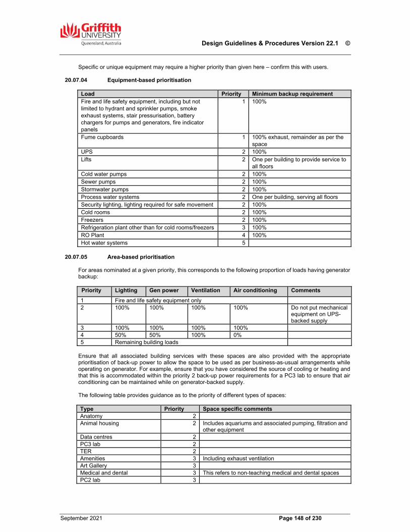
Design Guidelines & Procedures Version 22.1 ©
September 2021 Page 148 of 230
Specific or unique equipment may require a higher priority than given here – confirm this with users.
Equipment-based prioritisation Load Priority Minimum backup requirement Fire and life safety equipment, including but not limited to hydrant and sprinkler pumps, smoke exhaust systems, stair pressurisation, battery chargers for pumps and generators, fire indicator panels
1 100%
Fume cupboards 1 100% exhaust, remainder as per the space
UPS 2 100% Lifts 2 One per building to provide service to
all floors Cold water pumps 2 100% Sewer pumps 2 100% Stormwater pumps 2 100% Process water systems 2 One per building, serving all floors Security lighting, lighting required for safe movement 2 100% Cold rooms 2 100% Freezers 2 100% Refrigeration plant other than for cold rooms/freezers 3 100% RO Plant 4 100% Hot water systems 5
Area-based prioritisation
For areas nominated at a given priority, this corresponds to the following proportion of loads having generator backup:
Priority Lighting Gen power Ventilation Air conditioning Comments 1 Fire and life safety equipment only 2 100% 100% 100% 100% Do not put mechanical
equipment on UPS-backed supply
3 100% 100% 100% 100% 4 50% 50% 100% 0% 5 Remaining building loads
Ensure that all associated building services with these spaces are also provided with the appropriate prioritisation of back-up power to allow the space to be used as per business-as-usual arrangements while operating on generator. For example, ensure that you have considered the source of cooling or heating and that this is accommodated within the priority 2 back-up power requirements for a PC3 lab to ensure that air conditioning can be maintained while on generator-backed supply. The following table provides guidance as to the priority of different types of spaces:
Type Priority Space specific commentsAnatomy 2Animal housing 2 Includes aquariums and associated pumping, filtration and
other equipment Data centres 2 PC3 lab 2TER 2Amenities 3 Including exhaust ventilation Art Gallery 3 Medical and dental 3 This refers to non-teaching medical and dental spaces PC2 lab 3
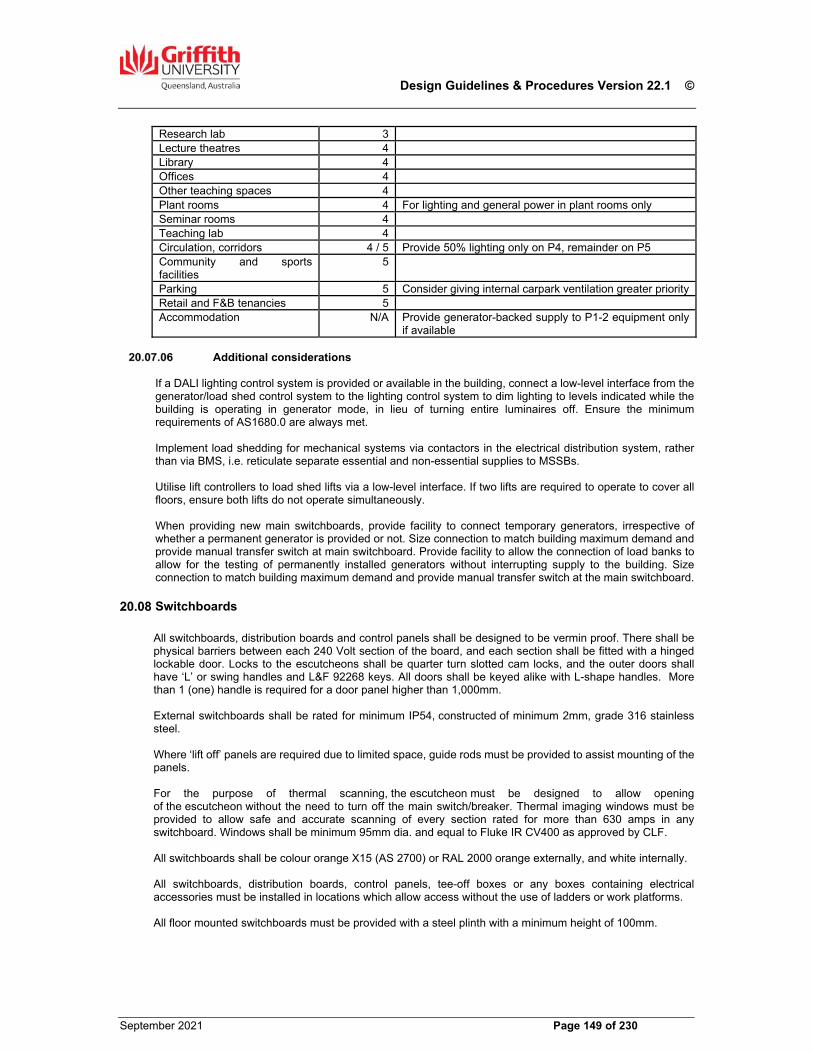
Design Guidelines & Procedures Version 22.1 ©
September 2021 Page 149 of 230
Research lab 3Lecture theatres 4Library 4 Offices 4 Other teaching spaces 4 Plant rooms 4 For lighting and general power in plant rooms only Seminar rooms 4 Teaching lab 4Circulation, corridors 4 / 5 Provide 50% lighting only on P4, remainder on P5 Community and sports facilities
5
Parking 5 Consider giving internal carpark ventilation greater priorityRetail and F&B tenancies 5Accommodation N/A Provide generator-backed supply to P1-2 equipment only
if available
Additional considerations If a DALI lighting control system is provided or available in the building, connect a low-level interface from the generator/load shed control system to the lighting control system to dim lighting to levels indicated while the building is operating in generator mode, in lieu of turning entire luminaires off. Ensure the minimum requirements of AS1680.0 are always met. Implement load shedding for mechanical systems via contactors in the electrical distribution system, rather than via BMS, i.e. reticulate separate essential and non-essential supplies to MSSBs. Utilise lift controllers to load shed lifts via a low-level interface. If two lifts are required to operate to cover all floors, ensure both lifts do not operate simultaneously. When providing new main switchboards, provide facility to connect temporary generators, irrespective of whether a permanent generator is provided or not. Size connection to match building maximum demand and provide manual transfer switch at main switchboard. Provide facility to allow the connection of load banks to allow for the testing of permanently installed generators without interrupting supply to the building. Size connection to match building maximum demand and provide manual transfer switch at the main switchboard.
Switchboards
All switchboards, distribution boards and control panels shall be designed to be vermin proof. There shall be physical barriers between each 240 Volt section of the board, and each section shall be fitted with a hinged lockable door. Locks to the escutcheons shall be quarter turn slotted cam locks, and the outer doors shall have ‘L’ or swing handles and L&F 92268 keys. All doors shall be keyed alike with L-shape handles. More than 1 (one) handle is required for a door panel higher than 1,000mm. External switchboards shall be rated for minimum IP54, constructed of minimum 2mm, grade 316 stainless steel. Where ‘lift off’ panels are required due to limited space, guide rods must be provided to assist mounting of the panels. For the purpose of thermal scanning, the escutcheon must be designed to allow opening of the escutcheon without the need to turn off the main switch/breaker. Thermal imaging windows must be provided to allow safe and accurate scanning of every section rated for more than 630 amps in any switchboard. Windows shall be minimum 95mm dia. and equal to Fluke IR CV400 as approved by CLF. All switchboards shall be colour orange X15 (AS 2700) or RAL 2000 orange externally, and white internally. All switchboards, distribution boards, control panels, tee-off boxes or any boxes containing electrical accessories must be installed in locations which allow access without the use of ladders or work platforms. All floor mounted switchboards must be provided with a steel plinth with a minimum height of 100mm.
Design Guidelines & Procedures Version 22.1 ©
September 2021 Page 150 of 230
Bottom entry floor mounted switchboards must be designed to accommodate easy installation of a cable gland at the point of entry and easy terminations to the relevant busbars or functional units. Provide access pits under and in front of the switchboard to allow for the connection of future cabling. Every switch and protective device on every switchboard shall have a label noting the following:
Name of load Trip setting and frame rating of protective devices, or current rating for isolators and switches Size, length, specification and current carrying capacity of the sub-mains cable to the load
All labels shall be engraved black text on white traffolyte. For fire and life safety services, labels shall be engraved white text on red traffolyte. Labels shall be secured by means of flat point screws, nuts and washers. Gluing or the use of self-tapping screws is unacceptable. Labelling within the switchboards for relays, contactors etc should be on stand off brackets. Seek advice from GU for the naming conventions for switchboards. Label outgoing cables from MSB and MSSBs with traffolyte labels, secured with zip-ties.
Main Switchboard The main switchboard shall be a Form 4b verified assembly, floor mounted, free standing and preferably modular construction. Provision shall be made to extend the main busbar systems in either direction. Switchboard components shall be Schneider, ABB, IPD or approved equal. Switchboard workshop drawings must be submitted for review and approval by GU and the consultant and include the following information for review:
Plan view Front and rear elevations Sectional views showing segregation, busbar arrangements and module layouts Single line diagram, including the size and current carrying rating of each section of busbar Schedule of equipment, including make and model for all items
The switchboard builder must also produce relevant verification documents to demonstrate that the proposed MSB complies with the current version of AS 61439. The verification documents must be submitted as part of the MSB workshop drawings and reviewed by a qualified third party Consultant (engaged by GU) to review. These documents shall be included in the Operation and Maintenance Manual. The design of the MSB must include the provision to monitor, detect and release the energy generated by an arc fault in accordance with AS3000. Where multiple transformers supply a single building, provide manually operated mechanical interlocks to allow the building to operate on a single transformer. Provide inspection windows to allow thermal imaging scan of all functional unit termination points rated 630 amps or higher. The inspection window should be Fluke, Flir or a Griffith University approved equivalent to AS. A vertical busbar arrangement is required to maximise cooling of the busbars by convection. Main switchboards shall have at least 25% spare capacity in physical connection space. Provide a variety of different frame sizes for future connections and ensure busbars are suitably rated. The MSB shall be supplied with a label noting:
Switchboard name Test certificate number Date of manufacture IP rating Origin, size and current rating of consumer mains Recommended information as specified in AS 61439.1
Non-fading laminated A3 size prints of the ‘As Constructed’ line diagram schematic drawings of the main switchboard and the electrical power reticulation to the building shall be provided in the Main Switch Room.
Design Guidelines & Procedures Version 22.1 ©
September 2021 Page 151 of 230
These drawings shall be ring bound into a plastic folder and placed in a suitable wall mounted rack holder. The main Switchboard line diagram must include the size, rating, and the length of all incoming and outgoing cable and the rating, model and manufacturer of all switchgear.
Distribution Boards The design of distribution boards shall be verified to AS 61439. Provide minimum Form 2 separation with a chassis rated for minimum 250A per phase. For pole quantities, provide
100% spare capacity on all distribution boards in science buildings 75% spare capacity in other academic buildings 50% spare capacity in non-academic buildings
Spare capacity of pole quantities is measured at practical completion. Distribution boards shall be provided to serve areas of heavy load concentration (e.g. workshops) and each laboratory. Locate distribution boards to be accessible for maintenance purposes without having to access the space itself. All light and power circuits are to be loaded to less than 75% of their rated capacity. All distribution boards shall be sized to allow for all incoming mains and outgoing cables and the positioning of Transformers, Terminal Blocks and Contactors such that cable to these items is completed in a neat and tidy manner. All distribution boards shall be supplied with a label noting:
Switchboard name Test certificate number Date of manufacture IP rating Origin, size and current rating of consumer mains Recommended information as specified in AS 61439.1
Current Schedules & Diagrams
Circuit schedules shall be typed and shall be provided at all switchboard positions. Schedules shall be secured in purpose made clear PVC covered holders. Circuit schedules shall indicate the room numbers or area served by the circuit. The schedule should also show where the Board is fed from and type and length of cable used to feed the board. An electronic copy, Word or Excel format, of the circuit schedules shall be included in the ‘As Constructed’ documentation. An A1 size non-fading laminated single line circuit diagram shall be provided for each DB and shall be hung on the internal face of the board door using an eye lid mechanism. If an updated circuit legend is required, the old sheet must be marked as superseded and left on site, behind the new sheet, for future reference.
Circuit Breakers Circuit breakers to final circuits shall be NHP, ABB or Schneider miniature circuit breakers or equal approved. If a refurbishment project results in more than 35% of the circuits on an existing switchboard being replaced or modified, then all lighting and power circuits on that switchboard shall be fitted with RCDs if they are not currently installed to the level required by the current edition of the Wiring Rules. Where existing Eaton Quicklag circuit breakers are installed, replace with NHP, ABB or Schneider circuit breakers with the correct adaptor to fit an existing ‘Eaton’ board.
Cable Numbering
Design Guidelines & Procedures Version 22.1 ©
September 2021 Page 152 of 230
All neutrals, earths and active cables shall be number ferruled to correspond to the circuit breaker number. All circuit breakers shall be numbered consecutively on the fascia from top to bottom on the left hand side then top to bottom on the right hand side, and also on the circuit breaker mounting bracket for ease of identification once the fascia has been removed. All active cables entering circuit breakers shall be installed as per manufacture’s recommendations. All control wiring shall be number ferruled with numbers as indicated on as constructed drawings. Neutral and earth bars shall have the same number of terminations as there are circuit breaker positions and be provided with two grub screws per terminal. Multi-joining of earths and neutrals into one joint prior to termination shall not be acceptable unless they are screened cable earthing. Screw type cable connections shall not be permitted within switchboards and distribution boards.
Telecommunications Equipment Room (TER) All power circuits within the TER shall originate from a dedicated distribution board installed within the TER. The poles within each shall be grouped into two sections, Section A (left) and Section B (right). Each Section shall be clearly identified using traffolyte type labels as DB.TER.A and DB.TER.B. Provision shall be made for a 50% spare pole capacity within each Section. (note that ‘Super High Immunity’ MCB+RCD combinations can be larger than one pole). The power supply to the distribution boards shall be directly from the building main switchboard via a separate feed and be capable of being maintained if the supply to another part of the building is switched off or from the UPS distribution board (where available). For each rack, provide two separate 32A power circuits, each protected by ‘Super High Immunity’ MCB+RCDs. One shall be supplied from DB.TER.A and the other from DB.TER.B, utilising matching pole positions on each switchboard. Each supply shall be terminated with a 32A, three pin single phase IEC 60309 socket outlet, rated for 250V, complete with locking plug retainer and isolator switch. Mount outlets on a Unistrut channel (HD galvanised or powder coated), suspended on threaded rods anchored to the concrete soffit over. If approved by DS, the power circuits may be rated for 20A and the outlets 16A, respectively. Provide one double GPO, mounted 800mm AFFL. This GPO shall have a face plate labelled ‘Telecommunication Equipment Only’ with a rocker switch colour selected to suit the type of supply (essential preferred, where available). Provide a cleaner’s outlet in each TER. Supply both of these outlets from the general distribution board and not the TER DBs. Lighting circuits within the TER shall be fed from a distribution board outside of the TER. Earth all racks and trays. Provide a Communications Earth Terminal at TER DB and connected to the building main earth. Coordinate design and any special requirements with GU DS.
Metering
Context GU has a centralised metering approach which collects energy, and other data from all electrical meters across all University buildings at all major campuses. The product is referred to as the Historian by GU and is a product sourced from OSIsoft. This system meets the NCC metering system requirements. The collection of this data uses Modbus IP registers as its main collection interface and electrical energy meters require either a compatible Modbus IP interface or to have their Modbus RTU communications pass through a serial to IP gateway to be presented on the GU network as Modbus IP registers for collection by the Historian. This approach allows the BMS and other Modbus IP compatible systems to read from the meters in parallel with the Historian as needed.
Design Guidelines & Procedures Version 22.1 ©
September 2021 Page 153 of 230
Additionally, GU has deployed its own power quality meters at appropriate points in the distribution system to aid in management of power factor correction, and power quality across its internal network. These meters are referred to as “Type 1” and in parallel with collection by the Historian require separate commissioning in GU’s Schneider Power and Energy Management system.
What to Meter
The metering system shall measure the following:
Total transformer output Total building input Total mechanical services input Individual Tenancy inputs Input for each chiller unit Individual laboratory distribution board Any other loads as nominated in the project Technical Brief or National Construction Code
Where possible the preference is for metering to occur in the MSB where the feed to the DB/MSSB is sourced.
Meter Types Type 1 – Schneider Electric ION 9000 or approved equivalent
Power quality meter where there are critical/sensitive electrical load requirements such as Research buildings, Data Centres, chiller plants, or where the building/facility takes the first load from the supply authority HV feeder (i.e. the site main switchboard).
A qualified specialist Electricity Metering Contractor must be engaged to fully commission the Type 1 metering installation into GU’s Schneider Power and Energy Management system, the full spectrum of the power quality function must be specified and fully commissioned.
Type 1 meters must be four quadrant meters, capable of measuring apparent, real and reactive power and energy consumption.
This meter shall also be remotely monitored by the existing Historian system.
Type 2 – Schneider Electric PM 5350, CETA PMC-512A or approved equivalent Shall be installed in all other buildings and situations where a critical load measurement is not required. Type 2 meters must have at least one (1) Modbus RTU RS485 serial port. Type 2 meters must be four quadrant meters, capable of measuring apparent, real and reactive power
and energy consumption. Meters must be installed, commissioned, and integrated to the Historian system. Each phase on the PMC-512A meter to be labelled with corresponding load using brother label tape. New loads added to existing PMC-512A meters shall be commissioned and checked for remote
monitoring by in the Historian system. Type 3 – EDMI Mk10 or Mk7 Patent approved for tenancy with onboard data retention
A Type 3 pattern approved meter is required for any tenancy space. The meter must be installed upstream of the Tenancy distribution board. These meters must be fully commissioned to be remotely monitored by the existing Historian system.
Installation
Where a new switchboard is constructed offsite injection test the CT’s and meter as installed to prove function prior to delivery to site. A Meter Commissioning Record is to be provided for all meters. A typical example is provided below. Electricity meters shall be located in a separate compartment within the board and additional space shall be provided within that compartment for future metering. Current transformers (CT’s) for metering shall be of class 0.5 accuracy. CT’s shall be located to allow for easy reading of the ratios printed on the face plate. A traffolyte label indicating the CT ratio shall be provided adjacent to the CT shorting block.
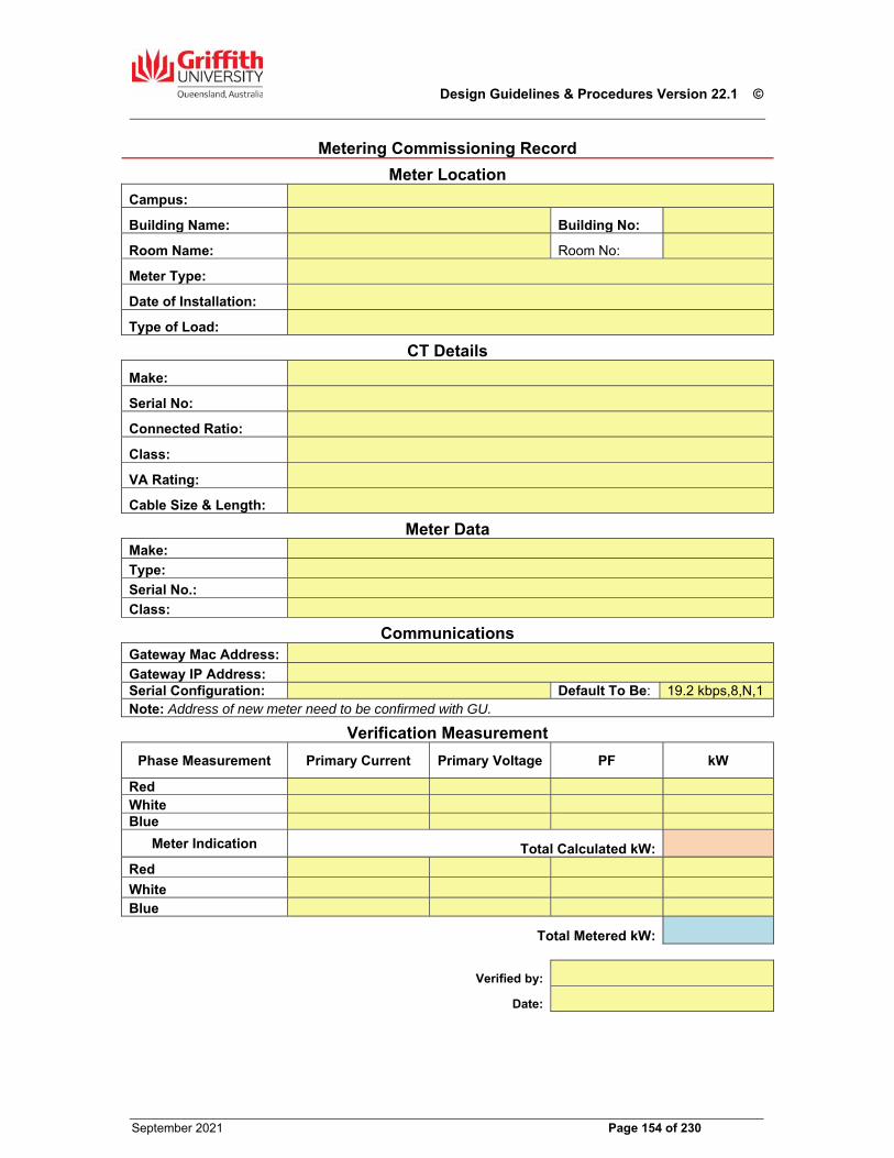
Design Guidelines & Procedures Version 22.1 ©
September 2021 Page 154 of 230
Metering Commissioning Record
Meter Location
Campus:
Building Name: Building No:
Room Name: Room No:
Meter Type:
Date of Installation:
Type of Load:
CT Details
Make:
Serial No:
Connected Ratio:
Class:
VA Rating:
Cable Size & Length:
Meter DataMake: Type: Serial No.: Class:
CommunicationsGateway Mac Address:
Gateway IP Address: Serial Configuration: Default To Be: 19.2 kbps,8,N,1Note: Address of new meter need to be confirmed with GU.
Verification Measurement
Phase Measurement Primary Current Primary Voltage PF kW
Red White Blue
Meter Indication Total Calculated kW:
Red
White Blue
Total Metered kW:
Verified by:
Date:
Design Guidelines & Procedures Version 22.1 ©
September 2021 Page 155 of 230
Metering Communications IP Network devices are to be capable of DHCP unless specifically granted an exemption by GU. IP addresses are managed by GU and will be allocated when location and MAC address of device are provided to GU. Meters that are natively IP are to present data via Modbus IP. Meters that are natively Modbus RTU are to have their data presented to the GU network via a Modbus Serial to IP gateway for collection by the Historian and other systems as deemed appropriate. Gateway devices are to support, at minimum, 5 TCP sessions for parallel systems to connect as needed. There is to be no more than 10 serial devices on any leg of a serial to IP gateway. GU preferred gateways are the Moxa 3180, 3280, or 3480 in conjunction with a Planet IPOE-162S PoE splitter, or pre-approved by GU equivalent. RS 485 serial comms cable is to be Belden 9841 or approved equivalent. Installed cables are to be labelled at each end with source and destination to aid in future fault finding and maintenance.
Power Quality
Each main switchboard must be provisioned for the connection of power factor correction (PFC), harmonic filtering and/or voltage regulation devices. Confirm requirements with GU in schematic design. Where not supplied by the building UPS or if UPS power is of insufficient quality, sensitive equipment which has specific power quality requirements must be supplied with a power quality device. Any such specific requirement must be discussed with the equipment user.If directed to provide as part of the works, the PFC should be sized to achieve a minimum 0.95 power factor when the building is fully operational. If directed to provide as part of the works, install power quality devices to achieve a THD value of less than 5%. The device must be able to provide the compensation for these mentioned parameters within less than 5ms. If directed to provide as part of the works, a voltage regulator should be installed to maintain a voltage fluctuation of less than 2% from the nominal voltage of 230V.
Cabling
Types & Sizes
Power and lighting cable shall not be less than 2.5mm², stranded copper conductors. Field control wiring for extra low voltage (less than 32 V AC./110 V DC.) shall be not less than 2.5mm² stranded copper. Control wiring within switch board can be 1.5mm² but once these control cables leave the board they are to be 2.5mm² and leave via a terminal block. Communications/Data cable used for RS-485 applications must be BELDEN 9841 or an exact electrical equivalent. Junction boxes, with identification labels shall only be used after written approval from the Superintendent. Cable exposed to sunlight in external locations must be UV rated.
Cable Entries Cable Entries to switchboards or equipment via gland plates or through panels shall be made using circular, orange-sheathed, cable and suitable compression glands. Double insulated flat cable may be used if entering through ducts or conduits. Non-magnetic gland plates and penetration cover plates shall be used when the cable rating exceeds 100 amps. Data/control cabling originating external to the building shall be fitted with an appropriately selected surge diverter to protect the electronic device from damage.
Design Guidelines & Procedures Version 22.1 ©
September 2021 Page 156 of 230
Containment
Provide zinc anneal cable trays for internal applications, minimum 1.25mm thickness with minimum 30% perforated hole area. Cable trays in external applications or otherwise exposed to the weather shall be fully galvanised and corrosion resistant and provided with ventilated and removable top hat cover sections to protect the entire length of the cabling. Cable trays, ladders and ducts shall be colour banded (300mm width) at a maximum of three metre intervals, and at each change of direction and either side of any partition or barrier. Trays and ladders shall have the following colour coding throughout the entire installation:
Orange X15 - for power, lighting and 240V controls. Grey - for extra low voltage or low voltage controls. White - for telecommunication and data services. Signal Red R13 - for fire services.
Where cable containment systems are painted, attach a label indicating the type of service (e.g. power, ELV, communications) for ease of identification. Conduits installed below ground for low or high voltage services shall be orange. Small conduits above ground shall be grey/white for painting. Large conduits above ground shall be orange and provided a protective metal hat section, suitably painted/powder coated to blend with the surrounding wall colour. Conduit saddles shall be of the stand-off type i.e. full saddle with spacer in exposed areas or on painted walls. Half saddles are not acceptable. All cable trays, ladders and ducts shall have 50% spare carrying capacity. All cable ladders or ducts leaving switchboards or load centres shall have 100% spare capacity up to the ceiling space.
Installation
All cables shall be installed in the ceiling of the floor they serve. Install all consumer mains, sub-mains and other major cabling on cable trays in ceiling spaces and on ceiling ladders where rising in cupboards in trefoil formation. Do not install major cabling runs over offices or other enclosed spaces. Where cables are not run on ladders and trays, every cable shall be supported clear of the ceiling grid or framing using ‘Unicon’ or approved equal push-in clips, or tied to a catenary wire. The spacing of clips and ties shall not exceed manufacturer’s recommendations. Adhesive fixed clips are not permitted. Where the number of final sub-circuit cables running parallel in the ceiling space exceeds six, a catenary must be used for support. Where the number of final sub-circuit cables running parallel in the ceiling space exceeds twenty-four, a cable tray must be used for support. Where cables are run in conduits, any connection between rigid and flexible conduit shall use an appropriate adaptor and not be adhesive or silicon joined. Conduits cast in slabs shall be 35mm min. dia. and their location shall be properly surveyed and clearly shown on the ‘As Constructed’ drawings. The laying of cable on top of the ceiling tiles or lining, or tying cables to ceiling grid, cable tray or duct support hangers is not permitted. All electrical accessories such as junction boxes, battery packs, control gear and lighting power sockets must also be supported clear of the ceiling grid or framing. Power circuits within partitions or wall cavities shall be installed vertically from the ceiling space to the outlet or connection position. Outlets within 1000mm of each other may be connected horizontally, providing the total horizontal route between successive outlets shall not exceed 1m. Cables shall not be installed diagonally. Where cables are installed within concealed areas or horizontally within partitions they shall be installed within conduit so that they can be withdrawn and so that sufficient segregation can be afforded if a new telecommunication cable is installed across its path. Services mounted beneath windows or viewing panels shall be duct mounted.

Design Guidelines & Procedures Version 22.1 ©
September 2021 Page 157 of 230
Where cables are installed through existing sealed penetrations, the barrier material shall be reinstated to meet the original rating or requirement. Where cable duct is used, provide three channel, aluminium duct. Select finish to suit architectural requirements. Install ducting above desk level. Where island rooms exist, these shall be provided with a minimum of 2 x 32mm spare conduits for future installation of additional power from the relevant distribution board.
Emergency Evacuation Lightning All emergency lights and exit signs shall be single-point and self-contained, suitable for use with a computerised testing and monitoring system. Emergency lights will generally be unmaintained and exit signs will generally be maintained. Install emergency lighting in all areas required by the NCC, AS2293 and where the sudden loss of lighting could pose a safety risk (e.g. laboratories, toilets, etc). All EEL shall be LED with Lithium Iron Phosphate battery technology. All new emergency and exit lighting shall be either be monitored by a Clevertronics Hive or a NHP StaniliteNexus RF (NCS) Platinum system. When working in existing buildings, refer to GU for details of existing monitoring systems. Generally:
Where neither monitoring system is in use in a building, provide new router or controller, associated GPOs and data outlets, as appropriate for the new EEL monitoring system. Connect the new monitoring system to the existing campus-wide system.
Where one monitoring system is already in use in a building, provide new EEL to match the existing and incorporate new fittings into the monitoring system.
Where both monitoring systems are already in use in a building, new fittings can be of either make and shall be provided based on cost effectiveness and compatibility, with new fittings incorporated into the existing monitoring system.
Where required, the contractor shall engage the incumbent maintenance contractor to undertake works to modify existing monitoring systems in conjunction with the supplier and provide all required information. Each luminaire shall have visible ID labels on the fitting for maintenance identification purposes. The ID for ‘Stanilite Nexus’ shall indicate the Building No./Router No./Floor Level/adjacent Room No./ the Fitting No./DB it is fed from e.g. N13/3/2/1.10/340/DB1A, and for Clevertronics shall be symbol Z, Floor Level/Fitting No./DB it is fed from, or Staircase No./Fitting No./DB it is fed from e.g. Z/2/01/DB1A or Z/ST2/01/DB1A. Emergency Evacuation Lighting System shall have a minimum five (5) year replacement warranty at the time of installation. If required, normal NCS LAN cabling is to be installed using NCS data cable (yellow). Prior to practical completion of refurbishment projects, a full test of the building system shall be carried out including a comparison of the previous and new test results to confirm that the installation and commissioning of the modified system have been undertaken correctly and that all parts of the building are functioning as required. Provide a theatre mask for all exit signs installed in lecture theatres and similar spaces. Confirm with users if activation of emergency or exit lighting during testing will negatively impact on operational uses of the space.
Lighting Protection
Lightning protection shall be provided to a building if recommended using the risk assessment criteria specified by AS 1768. Provide a copy of the risk assessment to GU for review, irrespective of whether a system is recommended by the assessment or not. Test points shall be provided at the lowest level of the building.
Design Guidelines & Procedures Version 22.1 ©
September 2021 Page 158 of 230
Provide surge protection on all cabling when cabling is installed external to the building (incoming or final sub-circuit). Provide Novaris, Erico, Dehn or approved equal.
Clocks Master clocks are no longer required on campus. No new master clock should be installed. In a refurbishment project, existing clocks should be decommissioned, and redundant services must be removed from site. Decommissioning work must not impair the operation of the clock system outside the refurbishment area.
Underground Electrical Services All underground electrical services shall be laid in sand with 75mm below and 150mm above and to sides. Trenches shall be backfilled only with selected fill and compacted in layers not exceeding 200 mm to a relative density of 90%. The minimum cover shall be not less than 600mm to the top of conduit. Concrete cover to conduits at a lesser depth will be allowed only with the written approval of the Superintendent. No backfilling of trenches shall be undertaken until photographs of all open trenches have been taken to identify the cable route, and the conduit installation has been inspected and approved by a GU representative. A photographic record shall be provided to the Superintendent to gain approval for back filling and must be included as part of ‘As Constructed’ documentation. The photographic record shall also show the installation of the marker tape Cable schedule, cable single line diagram, cable route with burial depth and pit & pipe verification checklist must be included in the as constructed documentation. The minimum size of underground conduit shall be 25mm diameter. All underground conduits >80mm diameter must be fitted with a bell mouth at pit entries to assist with future work. All penetration to building fabrics must be designed to avoid water ingress to the building, and all conduits must be sealed at both ends to avoid vermin and water ingress. All spare in-ground conduits shall be fitted with a 2.5mm2 TPI cable or a draw wire. All underground cable shall be double insulated cable, not less than 2.5mm2. Jointing of underground cables is not preferred but if a joint cannot be avoided, it may only be done with the written consent from the Superintendent, be done in a cable pit with an IP68 rated jointing kit and be suspended at 200mm (at least) above the bottom of the pit. Traffolyte ID labels must be provided (cable-tied to a cable or conduit) to every cable run in a pit to identify the cable (i.e. Consumer Main to N23). Maximum distance between pits on underground cable runs shall be sixty (60) metres. All pits shall have their lids marked with a recessed brass plate indicating the service installed and the route from the pit. Where available, drain the lowest pit in the conduit and pit network to a nearby storm water drain, including a back-flow prevention valve. If there is no adjacent storm water line available, a 2mx2m gravel pit must be provided under each pit with a grating suitably sized to drain the water into the pit. All underground pits must be cleaned out prior to practical completion to remove construction debris. Brass marker plates with lettering not less than 10mm high shall be installed on the building external wall at entry/exit points, at kerbs and road crossings and any changes in direction. The plate shall be installed flush and fixed by a mechanical fixing. Plates must include an arrow showing the direction of the cable run. In unpaved areas, the marker shall be set in a concrete pad not less than 300 x 300 x 200mm deep.
Testing
All faults detected during mandatory testing shall be immediately rectified and retested at no additional cost to GU.
Design Guidelines & Procedures Version 22.1 ©
September 2021 Page 159 of 230
On all projects, the Main Switchboard, distribution boards and load centres installed or modified within the project shall be checked using a Thermoscan infrared scanning unit or equivalent during the defects liability period by the Contractor at a time of maximum demand to check for faulty connections. All test results shall be recorded and provided to the Superintendent on completion of testing. At the conclusion of commissioning and testing, GU reserves the right to witness the testing of systems to verify operation is as per documentation and the DG&P. Liaise with GU for witness testing requirements in good time prior to the commencement of commissioning. Any defects found shall be made good prior to the issue of a Certificate of Final Completion and a complete report together with thermal photographs shall be provided on completion.
Product Substitution Where a product substitution is proposed for any specific electrical system/item nominated , a comprehensive engineering assessment report shall be produced for each item by the project Consultant to demonstrate product equivalence. The reports must assess all aspects of the electrical system/item and be supported with test certification, performance calculations and modelling plus all other supporting documents for both the original and proposed substitute items of equipment.
These reports must be provided to GU Engineering in a timely manner for review, and shall be prepared at no
additional cost to GU. Approval of the proposed substitute items is at the discretion of GU, however approval will not be unreasonably withheld.
Plant and Equipment As part of the building manual, a fully populated schedule of maintainable electrical equipment supplied in this
project must be provided in electronic format (combination of PDF, DWG, RVT and DOC file formats only).
Warranty
All major electrical components such as MSB’s, HV equipment, power quality equipment, generators and associated control systems must have a two (2) year manufacturers and installation warranty.
A warranty document for each major equipment must be supplied as part of building manual. All electrical equipment/accessories/items purchased for a project must be allocated a Griffith University
supplied project number for future warranty claim reference.
Renewable Energy Systems
The renewable energy system installation and associated services shall be designed, supplied, installed, tested and maintained to the requirements of the following standards:
Clean Energy Council Install and Supervise Guidelines for Accredited Installers AS/NZS 5033 - Installation and safety requirements for photovoltaic (PV) arrays AS/NZS 1768 - Lightning Protection AS/NZS 1170.2 - Wind Loads AS/NZS 4777.1 - Grid Connections of Energy Systems via Inverters EX 01960 - Energex Approved Grid Protection Relays Energex STNW1174 - Standard for Low Voltage Embedded Generation Connections or Energex
STNW1175 - Standard for High Voltage Embedded Generation Connections
Renewable Energy Equipment Identification and Asset Data
Equipment identification shall be in accordance with the requirements of GU's Equipment Data Collection Procedure.
Design Guidelines & Procedures Version 22.1 ©
September 2021 Page 160 of 230
Inverters
Where multiple inverters are installed, they must be fitted with isolators to enable quick and safe inverter replacement. Installation of a custom-built inverter is not acceptable. Inverters shall be installed in a location that will allow safe and easy future maintenance access. All renewable energy generation systems must be designed, installed and commissioned in a way that will allow the system plus the derived data to be displayed for educational purposes. Inverter communications port shall conform to the Sunspec protocol and at a minimum shall have the ability to for the following to be remotely set:
Real power output Power factor/VAR’s Inverter grid protection device (a.c. output relay)
Inverters shall have the ability to be remotely read by the University’s OSISoft Pi Historian system and the following Sunspec registers:
Voltage (a.c.) Current (a.c.) Real power (a.c.) KVA (a.c.) KVAr (a.c.) Power factor Voltage for d.c. each input Current for d.c. each input Error messages Inverter temperature
The inverters shall be able to actively change the output power to match the load at the network coupling point. Each inverter shall be connected to a Bluelog XC site controller (or approved equivalent) The inverter output at the PV-DB shall be metered by an NMI pattern approved meter and shall have Modbus communications. The inverters shall have a minimum 98% uptime guarantee. The inverter is to be certified compliant to AS/NZS 4777.2:2020 The inverter shall have a warranty of 10 years or more. Inverters shall be installed in plant rooms however if this is not practicable, installation is preferred to be undercover.
Solar Panels
Any shaded panels shall have an optimiser. This includes any panel that over time may become shaded due to growing trees. Optimisers on all panels are preferred to maximise the output per panel and for record-keeping purposes. All PV strings shall be able to be monitored for voltage and current output. This can be done via the inverter if each string is separately fed into the inverter and can be measured. PV Strings should not be paralleled at the array. All solar arrays shall be shut down and all cables from the inverter to the array shall be at no more than 35V d.c. in the case that a.c. voltage is lost to the inverter.
Design Guidelines & Procedures Version 22.1 ©
September 2021 Page 161 of 230
Solar panel performance shall not degrade faster than what is stated on the solar panel datasheet. The solar panels must have a minimum product warranty of 12 years and a performance warranty of 25 years. Solar panels shall have an expiry date on the Clean Energy Council website of no early than 12 months from the installation date. All panels shall be mounted at a minimum of 10° tilt to allow for self-cleaning and where possible tilted to the north to increase yearly output.
Communication
All meters, gateways, grid protection relays and inverters that are installed must communicate with the GU network and log to the data management platform, OSIsoft Pi Historian. The Modbus register values of the device will be made available to the GU and confirmed they are being logged at commissioning.
Roof Placement
Solar panels clearances shall be as below:
1500mm from the edge of the roof. 1000m from any box gutter to ensure adequate space for gutter cleaning 1000mm from any roof-mounted plant No more than two rows of panels may be butted next to each other 600mm walkway between panels 100mm from the bottom of the panel to the roof
Mounting rails must be oriented to facilitate the natural flow of air under the PV panels. There are to be no roof penetrations on Kliplok or other non-penetrative roof types except for cable entries. All fixings to the roof must be via a non-penetrative clamp. All rooftop cabling to be mounted on a cable tray with lid and run on the roof where possible. Trays and lids must be hot-dipped galvanised (Galvabond or similar products are not acceptable) If the tray is visible from the ground, the tray is to be powder coated the same colour as the roof or wall it is fixed to.
Other
Each LV transformer to which an inverter is connected shall have a ComAp Intelipro (or approved equivalent) grid protection relay connected downstream that trips any inverter connected as required by STNW1175 or STNW1174 (whichever is relevant). Where a battery or other energy storage system is installed, the location must facilitate both access and maintainability and shall be mutually agreed upon with GU. The battery system space must be adequately illuminated, ventilated and installed with the required firefighting system. Any devices that could generate electrical noise must be fitted with a relevant power quality devices to suppress the negative effect on other building loads.
Electrical Design Requirements
Griffith University reserves the right to review any documentation, calculations and the like relating to electrical services. This may include but is not limited to:
Maximum demand calculations for each switchboard, net and with spare capacity Voltage drop calculations
Design Guidelines & Procedures Version 22.1 ©
September 2021 Page 162 of 230
Cable sizing calculations Protection/discrimination study and device settings Illumination level calculations Lightning protection system risk assessment Line diagram schematic of the main switchboard with fault current withstand rating, size and ratings
of switchgear and cables entering or leaving the board. Details of distribution boards including number of poles, rating of busbar and main switch and
number of spare poles. Details of lightning protection, earthing schematic and fault loop impedances for non RCD circuits. Layout of cable tray/ladder routes Layouts of underground services Schedule of luminaire types and outlets Luminaire layouts and switching/control schematics Locations, types and classifications of emergency lighting.
All lighting and power drawings are to show the Circuit Breaker No. and distribution board feeding the circuit. The use of ‘L’ and ‘P’ on the design, tender or ‘As Constructed’ drawings, will not be accepted by GU.
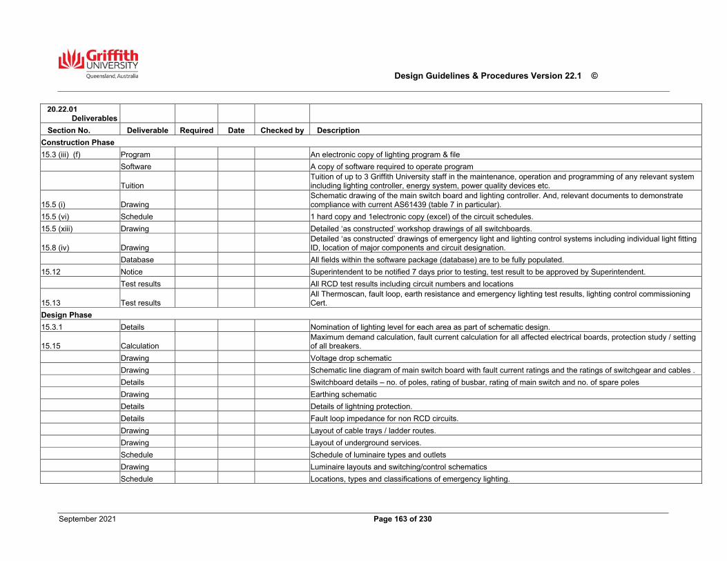
Design Guidelines & Procedures Version 22.1 ©
September 2021 Page 163 of 230
Deliverables
Section No. Deliverable Required Date Checked by Description
Construction Phase
15.3 (iii) (f) Program An electronic copy of lighting program & file
Software A copy of software required to operate program
Tuition Tuition of up to 3 Griffith University staff in the maintenance, operation and programming of any relevant system including lighting controller, energy system, power quality devices etc.
15.5 (i) Drawing Schematic drawing of the main switch board and lighting controller. And, relevant documents to demonstrate compliance with current AS61439 (table 7 in particular).
15.5 (vi) Schedule 1 hard copy and 1electronic copy (excel) of the circuit schedules.
15.5 (xiii) Drawing Detailed ‘as constructed’ workshop drawings of all switchboards.
15.8 (iv) Drawing Detailed ‘as constructed’ drawings of emergency light and lighting control systems including individual light fitting ID, location of major components and circuit designation.
Database All fields within the software package (database) are to be fully populated.
15.12 Notice Superintendent to be notified 7 days prior to testing, test result to be approved by Superintendent.
Test results All RCD test results including circuit numbers and locations
15.13 Test results All Thermoscan, fault loop, earth resistance and emergency lighting test results, lighting control commissioning Cert.
Design Phase
15.3.1 Details Nomination of lighting level for each area as part of schematic design.
15.15 Calculation Maximum demand calculation, fault current calculation for all affected electrical boards, protection study / setting of all breakers.
Drawing Voltage drop schematic
Drawing Schematic line diagram of main switch board with fault current ratings and the ratings of switchgear and cables .
Details Switchboard details – no. of poles, rating of busbar, rating of main switch and no. of spare poles
Drawing Earthing schematic
Details Details of lightning protection.
Details Fault loop impedance for non RCD circuits.
Drawing Layout of cable trays / ladder routes.
Drawing Layout of underground services.
Schedule Schedule of luminaire types and outlets
Drawing Luminaire layouts and switching/control schematics
Schedule Locations, types and classifications of emergency lighting.
Design Guidelines & Procedures Version 22.1 ©
September 2021 Page 164 of 230
21.00 Communication & Data Services
All the requirements of this Section are Mandatory.
System Generally All GU campuses are serviced by a structured cabling system comprising a flexible cabling infrastructure that can support computer, telephone, and audio-visual systems independent of their manufacturer. In this structured cabling system, each information outlet (IO) is wired to a central point using a star topology, facilitating system interconnection and administration. The current guidelines seek to ensure there is adequate facility for all Communication and Data Services to cater for the exponential increase and reliance on cabling and wireless infrastructure in the future. The requirements for a structured cabling system as described in this document has been prepared by the Network and Collaboration Services (NCS) and shall apply to all new cabling installations on all GU campuses, including the refurbishment of existing installations. Consultants and Contractors shall not depart from these requirements unless it is stated otherwise in the Technical Brief, or they are advised in writing by the Superintendent on the advice and approval of NCS.
Subsystems
The structured cabling system may consist of any or all of the following subsystems;
Work Area subsystem – The connection between the IO and the equipment in the work area is provided by the work area subsystem. It consists of fly leads, adapters and other transmission electronics. Horizontal subsystem – The horizontal subsystem connects the telecommunications equipment room to the work areas. It consists of the transmission media, the associated hardware terminating this media and the IOs.
Building Backbone subsystem – The main cable route between floors within a building and between Telecommunications Equipment Rooms (TER) within a building is called the building backbone subsystem. It consists of the transmission media and the associated terminating hardware. Access to the building backbone subsystem is via telecommunications risers on each floor. The building backbone subsystem is only used for the through passage of cables. No cables shall be terminated in telecommunications risers. Administration subsystem – The administration subsystem joins all of the subsystems together. It consists of labelled hardware for circuit identification and patch leads or jumper wire for creating circuit connections. Equipment subsystem – The equipment subsystem consists of electronic communications and audio visual equipment in the telecommunications equipment room and the transmission media required terminating this equipment on distribution hardware. This equipment shall not be installed in telecommunications closets.
Campus subsystem – The campus subsystem provides the circuits between buildings and must include two paths to each building in order to provide redundancy. This subsystem includes the entrance facilities into the building, transmission media, associated terminating hardware, and electrical protection devices to mitigate harmful voltages when the media is exposed to lightning and/or power surges.
General Requirements All Systems
Types of Use As a minimum, the structured cabling system shall be capable of supporting future services that require up to 1000 Mhz signaling and Power over Ethernet (PoE) using a mix of fibre optics and up to Category 7 structured cabling for (but not limited to) the following protocols; Data Communications
IEEE 802.3 IEEE-802.3ab (1000BaseT) IEEE-802.3af (Power over Ethernet)
Design Guidelines & Procedures Version 22.1 ©
September 2021 Page 165 of 230
IEEE-802.3at (Power over Ethernet Plus) IEEE 802.11 (Wireless LAN) IEEE 802.1x (Port based network access control) IEE – 802.3bt (Universal PoE)
Voice Communications
IP Telephony Analogue telephone EFTPOS ADSL Services
Video
IP Telephony with video and audio Analogue video Digital video Composite baseband video and audio Broadband Video RGB baseband video 3D Imaging and printing
Standards Conformance
General - All cabling work shall be implemented and completed in strict compliance with Griffith University Design Guidelines and the latest regulations and standards issued or endorsed by the Standards Association of Australia and Australian Communications Authority. International Standards shall be used where there are no applicable Australian Standards. The requirements outlined in this document, where different to the Standards, the GU Design Guidelines will take precedence. Where differences occur between Australian Standards and International Standards, the Australian Standards will take precedence. Quality Standard - The Contractor shall have a Quality System in place that conforms to the requirements of AS/NZS 9000 series of quality related Standards or shall provide details of progression towards accreditation to the relevant Standard. NCS approved Contractors shall install, terminate and test cabling at GU unless otherwise approved in writing by NCS. Communications Standards - The cabling materials and practices shall result in a structured cabling system that meets or exceeds the latest edition at the time of all relevant communications standards including but not limited to:
IEEE 802.3 CSMA/CD Access Method Physical Layer Specifications for 10 Mbps Ethernet
IEEE 802.3 Supp 1 Twisted Pair Media Attachment unit (MAU) and Baseband Medium Type 10 Base T (Section 14 of IEEE 802.3)
IEEE 802.3u CSMA/CD Access Method Physical Layer Specifications for 100 Mbps Ethernet
IEEE 802.3ab CSMA/CD Access Method Physical Layer Specifications for 1000 Mbps Ethernet
IEEE 802.3an 10GBASE-T 10 Gbit/s (1,250 MB/s) Ethernet over unshielded twisted pair (UTP)
IEEE 802.3at/bt Power over Ethernet enhancements
IEEE 802.11 Wireless networking standards
Design Guidelines & Procedures Version 22.1 ©
September 2021 Page 166 of 230
Australian Standards and Legislation - The cabling materials and practices shall comply with the latest edition at the time of all relevant Australian Cabling Standards including but not limited to the following;
AS/ACIF S009:2013 Installation requirements for customer cabling (wiring rules) requires cabling providers to comply with the relevant Commonwealth, State and Territory occupational health and safety requirements including, but not limited to, building code requirements.
AS/CA S008:2010 requirements for customer cabling products (supersedes AS/ACIF S008:2006
Telecommunications Cabling Provider Rules 2014 (CPRs)
Telecommunications Act 1997 -2014 revision
AS/NZS 3080:2013 Telecommunications Installations – Generic cabling for commercial premises (ISO/IEC 11801:2002, MOD) (Incorporating Amendment 1:2009)
AS/NZS 3084:2003 Telecommunications Installations Telecommunications Pathways and spaces for Commercial Buildings (Incorporating Amendment 1:2007) (ISO/IEC 18010:2002, MOD);
AS/NZS ISO/IEC 14763.3:2012
Telecommunications installations – Implementation and operation of customer premises cabling – Acceptance testing of optical fibre cabling;
AS/NZS ISO/IEC 61935.1:2012
Testing of balanced communication cabling in accordance with ISO/IEC 11801 – Installed cabling
AS/NZS ISO/IEC 61935.2:2006
Testing of balanced communication cabling in accordance with ISO/IEC 11801 – Patch cords and work area cords
AS/NZS 3085.1:2004 Telecommunications Installations - Administration of communications cabling systems – Basic requirements
AS/NZS ISO/IEC 24702:2007
Telecommunications installations - Generic cabling –Industrial premises (Incorporating Amendment 1:2009)
AS/NZS ISO/IEC 15018:2005
Information technology – Generic cabling for homes
Queensland Government Enterprise Architecture
Information and communication technology ICT cabling infrastructure technical standard v3.0 Queensland Government Chief Information Office
Other Standards - The cabling materials and practices shall comply with the latest edition at the time of all other relevant standards including but not limited to:
IEC 801 PT 3 & 4 Immunity to radiated electromagnetic fields and electrical transients
ISO/IEC 11801 For Cabling Standards
Other Requirements
Workplace Health & Safety Compliance - All work shall comply with the GU WH&S procedures for Contractors. Sealing of Openings – The Contractor shall carry out the following sealing of openings associated with cabling installation;
Effectively seal all openings, made or provided, in or through building walls, floors, ceilings, and other fixtures after cable reticulation to ensure that the integrity of the barrier penetrated is maintained.
Effectively seal all cable duct openings above ground level, and all cable entries into trenches or buildings to prevent the ingress of moisture and the entry of rodents and fire where applicable.
Ensure that all spare conduit and cable entries into TERs are effectively plugged and sealed to prevent the ingress of moisture, entry of rodents or fire penetration.
Ensure that all openings through roofs and external walls are made weatherproof. Where necessary, this will include the installation of flashing and/or rain hoods to prevent the entry of driving rain, seepage, etc.
Ensure all fire rated sealing shall be done in accordance with the requirements of the BCA and AS3000. Particular attention shall be given to penetrations through fire rated barriers such as walls, floors, ceilings and doors. The barriers must have their fire- stopping capabilities restored after the
Design Guidelines & Procedures Version 22.1 ©
September 2021 Page 167 of 230
cabling, conduit or cable tray penetrations have been made. ‘Hilti Firestop’ foam, blocks, logs, plugs and mastic, or tested equal, are the preferred materials for the sealing of penetrations through fire rated floors and walls, installed strictly in accordance with the manufacturers printed instructions.
Material Colours - All exposed materials shall be of a colour, which is consistent with the surrounding decor and shall be approved by the Superintendent.
The colour of telecommunications cable trays, conduits etc. shall conform to the requirements listed in Section 20.00 Electrical Services. Painting and Corrosion - The Contractor shall be held responsible for corrosion protection and the painting of all brackets, supports, cable ladders weather shields, etc. being supplied and/or installed. The Contractor shall also be responsible for the restoration of any damaged paintwork on equipment and accessories to the supplier’s finish, or to a matching finish approved in writing by the Superintendent. Testing Documentation - The Contractor shall provide a printed and electronic copy of the test summary results for all cabling with detailed test results provided in PDF file format as outlined. Accredited installers must be trained and certified for the test equipment used for testing. Certificates of competence must be provided when requested. Fibre optic cabling test results shall be based on using power meter and a light source providing the optical loss of fibre using 850 and 1300nm in both directions for multimode fibres and 1310 and 1550nm in both directions for single mode fibres. In addition to this, all fibres shall be tested using OTDR and a printed copy of the waveform parameters shall be submitted for each fibre of the cable tested. Short runs of optical fibre shall be tested by the Contractor as required by NCS. Additionally, all testing documentation must be submitted to the relevant cable provider for warranty purposes. A copy of the Warranty Certificates must be submitted to the NCS representative. As Constructed or Final Build documentation – All new or updated campus cable, optical fibre, copper services or powered fibre runs will require an as built or final drawing to be submitted within in 10 working days from practical completion. Final documentation is to be submitted in CAD format and overlaid on the most up to date and to scale campus drawing. Campus drawings are available from Planning Design & Construction (PD&C), Corporate Services. For minor works, a scaled drawing in .pdf (Acrobat) format may be submitted at the discretion of the NCS Project Manager Identification Labelling - Identify (label) all cables and equipment as outlined in this document for each specific subsystem. Record Books - Ensure that distribution frame record books pertaining to new installations and changes are updated and accurate for each subsystem. Record entries shall be neat, tidy and completed in pencil. Redundant Cabling - The Contractor shall be responsible for the following when replacing existing cables;
The end to end removal of all redundant cabling resulting from a building or room refurbishment. This
includes any cabling disconnected and not required, any old cabling left in walls, access poles, work station partitions, on cable trays, or in (wall and floor) ducting.
The removal of any underground cable made redundant by the running of a new replacement underground cable.
The removal of the cabling is to be from either the patch panel to outlet, from ‘CommScope’ frame to outlet or in the case of underground cable termination point to termination point at both ends.
In all cases records are to be rewritten to reflect the changes. A list of outlets made redundant during a refurbishment is to be created and provided to NCS as part
of the ‘as built’ information by the Contractor to ensure accurate updating of records. Existing labelling of redundant outlets shall be blanked out on the patch panel end to show that the
previous cabling is no longer existent Cabling in Partition or Wall Cavities - The requirements of Section 20 Electrical Services, shall apply equally to the installation of communication and data cabling. Also, cables shall not be installed diagonally, and the use of wall frames is not permitted as a cable tray path. Notification of non-compliant cabling installations - When non-compliant cabling is identified during site
Design Guidelines & Procedures Version 22.1 ©
September 2021 Page 168 of 230
inspections, or during normal work activities, notification of this non-compliance shall be provided to the NCS representative and the PD&C Project Manager in a written format. Non-compliant cabling is pre-existing cabling that does not meet the GU or Australian cabling standards. NBN (National Broadband Network) - NBN access and advisory policies are under development. Any NBN access requirements are to be forwarded to NCS for appraisal and analysis.
Performance Warranties, Guarantees & Auditing
Installation testing – 100% of all cabling shall be tested prior to commissioning. All tests shall be from end-to-end (patch panel to IO inclusive) and shall include the connectors and terminating equipment fixed in their final position at both ends at the time of the testing. These test results shall use IO identification as reference. All as installed cable lengths shall be recorded and submitted with the test results, to the Superintendent. Electrical acceptance tests shall be carried out on all Cables following the termination and labelling of the cabling in compliance with the relevant standards. The tester used shall have a current calibration certificate from the manufacturer’s accredited certification facility.
Post Installation test of all fibre optic cables shall be carried out with the following minimum criteria;
Optical Loss end to end including connectors Physical condition by the use of an OTDR
Warranty - The installation Contractor shall provide a minimum twenty-five (25) year warranty backed by the cabling manufacturer (Commscope) and a copy of any additional Contractor warranties. All warranties will commence from the date of certification and shall be submitted to the NCS representative within four weeks of the commissioning of the installed cable. All components of the structured cable system shall be matched, tested and guaranteed as a channel system. Substitution of nominally equivalent components in lieu of vendor matched components will not be allowed unless specifically authorised in writing by the Superintendent. Multi-pair telephone lead-in cables are to be continuity tested and the results recorded and provided to NCS. Auditing - NCS reserves the right to inspect any cabling installation at any time. Campus cabling shall include a process to cover the auditing of cabling work to verify that it has met the specified standard. This audit may be completed by NCS or by invited industry specialists external to GU. The audit shall not be completed by the installation staff that installed the cabling. The Contractor must rectify any faults, omissions or defects detected within three (3) working days of these inspections.
Scheduling
No networking equipment shall be installed until a clean, dust-free and secure telecommunications equipment room (TER) is provided. It is preferred that the building has reached practical completion before network equipment is installed. Ten (10) working days from Practical Completion must be allowed in the project schedule for network equipment installation, testing and commissioning.
Refurbishments of Minor Internal Works
Where internal building works or alterations are necessary, all in-place networking equipment will be required to be continuously housed in a clean, air-conditioned, dust-free and secure environment. Internal works that envelope or encroach upon a telecommunications equipment room (TER) or dust and heat sensitive equipment will require a re-housing or temporary solution agreement to be reached between NCS and PD&C. All costs associated with continuity of service (like for like) to the local clients will be borne by the initiating project.
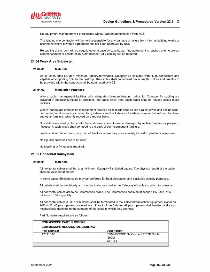
Design Guidelines & Procedures Version 22.1 ©
September 2021 Page 169 of 230
No equipment may be moved or relocated without written authorisation from NCS The leading site contractor will be held responsible for any damage or failure from internal building works or alterations where a written agreement has not been approved by NCS Re-cabling of the room will be negotiated on a case by case basis. If no agreement is reached prior to project commencement or construction, Commscope Cat 7 cabling will be required.
Work Area Subsystem
Materials All fly leads shall be, at a minimum, factory-terminated, Category 6a shielded with RJ45 connectors and capable of supporting 10G to the desktop. The cables shall not exceed 5m in length. Colour and quantity to be provided within the contract shall be nominated by NCS.
Installation Practices Where cable management facilities with adequate minimum bending radius for Category 6a cabling are provided in modular furniture or partitions, the cable slack from patch leads shall be housed inside these facilities. Where inadequate or no cable management facilities exist, leads shall be laid against a wall and behind semi-permanent furniture such as desks, filing cabinets and bookshelves. Leads must never be laid next to chairs and other furniture, which is moved on a regular basis. No cable slack shall protrude into the work area where it can be damaged by mobile furniture or people. If necessary, cable slack shall be taped to the back of semi-permanent furniture. Leads shall not be run along any part of the floor where they pose a safety hazard to people or equipment. No zip lock cable ties are to be used. No labelling of fly leads is required.
Horizontal Subsystem
Materials All horizontal cables shall be, at a minimum, Category 7 shielded cables. The physical length of the cable shall not exceed 90 meters. In some cases Shielded cable may be preferred for heat dissipation and stackable density purposes. All outlets shall be electrically and mechanically matched to the Category of cables to which it connects. All horizontal cables are to be Commscope brand. The Commscope cable must support PoE and, at a minimum, 10G capability All horizontal cables (UTP or Shielded) shall be terminated in the Telecommunication equipment Room on 24Port, RJ 45 patch panels mounted in a 19” rack of the Cabinet. All patch panels shall be electrically and mechanically matched to the category of the cable to which they connect. Part Numbers required are as follows;
COMMSCOPE PART NUMBERS
COMMSCOPE HORIZONTAL CABLING Part Number Description 1711163-1 COMMSCOPE NetConnect F/FTP Cable
(500M WHITE)
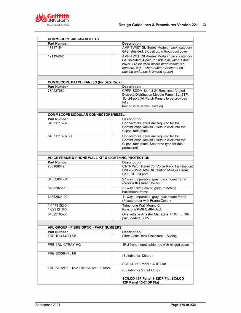
Design Guidelines & Procedures Version 22.1 ©
September 2021 Page 170 of 230
COMMSCOPE JACKS/OUTLETS Part Number Description 1711716-1 AMP-TWIST SL-Series Modular Jack, category
6AS, shielded, 8-position, without dust cover
1711343-2 AMP-TWIST SL-Series Modular Jack, category 6A, shielded, 4 pair, for side exit, without dust cover. (To be used where bend radius is a concern, e.g. - when outlet terminated on ducting and there is limited space)
COMMSCOPE PATCH PANELS (for Data Rack) Part Number Description 760237050 CPPR-SDDM-SL-1U-24 Recessed Angled
Discrete Distribution Module Panel, SL, STP, 1U, 24 port (All Patch Panels to be provided fully loaded with Jacks - always)
COMMSCOPE MODULAR CONNECTORS/BEZEL Part Number Description64671116-07 Connectors/Bezels are required for the
CommScope Jacks/Outlets to click into the Clipsal face plate.
64671116-07SH Connectors/Bezels are required for the CommScope Jacks/Outlets to click into the Clipsal face plate (Shuttered type for dust protection)
VOICE FRAME & PHONE WALL KIT & LIGHTNING PROTECTION Part Number Description 760180042 CAT6 Patch Panel (for Voice Rack Termination)
UNP-6-DM-1U-24 Distribution Module Panel, Cat6, 1U, 24 port
64552034-01 27 way jumperable, gray, backmount frame (order with Frame Cover)
64552022-10 27 way Frame cover, gray, matching backmount frame
64552034-00 11 way jumperable, gray, backmount frame (Please order with Frame Cover)
1-1479152-3 1-2291216-3
Telephone Wall Mount Kit Keystone KM8 Cat6A Jack
64622105-00 Overvoltage Arrestor Magazine, PROFIL, 10- pair, loaded, 500V
AFL GROUP - FIBRE OPTIC - PART NUMBERS Part Number DescriptionFRE 1RU MOD SB Fibre Optic Rack Enclosure – Sliding
FRE-1RU-CTRAY-HG 1RU front mount cable tray with hinged cover
FRE-SC06H-FL1/6 (Suitable for 12core)
SC/LCD 6P Panel 1-6HP Flat FRE-SC12D-FL1/12 FRE-SC12D-FL13/24
(Suitable for 2 x 24 Core)
SC/LCD 12P Panel 1-12DP Flat SC/LCD 12P Panel 13-24DP Flat
Design Guidelines & Procedures Version 22.1 ©
September 2021 Page 171 of 230
Horizontal fibre optic cable shall only be installed when specified in writing by NCS and shall be a minimum of 2 core fibre to each workstation area. Powered fibre may also be considered for horizontal cabling purposes in consultation with NCS.
All fibre optic cable shall only be installed using LC Duplex connectors on 19” rack mounted optical fibre termination panels with appropriate labelling ID strips, or as otherwise instructed in writing by an NCS representative.
Mechanical Protection of Cables The Contractor shall supply and install approved mechanical protection on all horizontal cables. In work areas
and public places, horizontal cables must be fully enclosed within cable ducts.
In ceilings, telecommunications equipment rooms, telecommunications risers, and other non- public areas, mechanical protection shall consist of cable ladders, cable trays, conduits, ‘Unicons’ and catenary wires. Cables shall be supported clear of the ceiling structure by approved cabling support systems. Under no circumstances shall cables be laid on ceiling tiles, attached to a ceiling support, or other services. New Velcro cable ties are to be used when adding new cabling to existing pathways or new installations.
Cable Ducts Cable ducts shall be installed in work areas and public places for the containment of telecommunications cables, where nominated. These ducts shall be;
Identical to existing ducts in that location, if they exist Approved by NCS Located at a height consistent with existing ducts. Where no duct currently exists, the installer shall
consult the Superintendent to determine the appropriate height for fixing A minimum of 50mm deep or be able to ensure bend radius requirements
Cable Supports
If ten (10) or more cables run in ceiling space in parallel, a cable tray must be used unless otherwise specified by an NCS representative in writing. The cable tray shall be installed no less than 150mm from the underside of any slab or cable tray carrying other services, and no less than 300mm from any roofing material unless varied in writing by an NCS representative. On exiting the cable tray system, cables can be directed to their ultimate connection point through the use of catenary wires to the top of service columns or partition walls on which the workstation outlet is located. Ensure that the ends of catenary wires are not attached to the cable trays, but are anchored to strong and stable structural elements such as columns, walls or slab beams. Where cables enter the Telecommunications Equipment Room (TER) above the racks, large bend radius cable ladders shall be used to facilitate the dropping off of cables into racks. All cables shall be tied to rack mounted cable tray using Velcro cable ties.
Cable Hangers Cable hangers shall only be used in circumstances where it is not possible to install cable trays, ladders, or conduits. Written approval must be obtained from NCS prior to the installation and use of cable hangers. If approved, cable hangers should only provide strain relief or ensure that the radius of any bend in the cable route conforms to the standards. Cable hangers must be a type which is approved by the cable manufacturer as suitable for the cable type, and must be installed to conform to the manufacturer’s correct cable installation procedures including spacing and attachment requirements.
Conduits
Design Guidelines & Procedures Version 22.1 ©
September 2021 Page 172 of 230
Where cables traverse inaccessible ceiling areas, such as those behind lock-in type ceiling tiles, drywall and plaster, conduits with draw wires shall be used for the distribution and containment of cables. Provide n+1conduits, where n is the quantity required for known services at time of installation. Inspection type tees, bends, etc. are permitted if approved by NCS. Draw wires shall be provided in all conduits after installation for possible future cabling additions, and shall be replaced in existing conduits after the initial draw wire has been used for new cabling.
Separation For UTP and shielded cable, the minimum separation between the fixed telecommunications cabling and parallel runs greater than 3 metres of low voltage (240V) fixed electrical cabling shall be at least 150mm for performance and noise reduction reasons. Separation from other electrically noisy environments such as power distribution mains, sub- mains, fluorescent light fittings and halogen down light transformers shall be 150mm. Shielded cable has greater heat dissipation properties and may therefore be a better option for stackable density purposes Optical fibre and Powered fibre will require zero separation if the cables are separated by a barrier of durable insulating material. All separation requirements are to adhere to AS/ACIF S009:2013
Installation Practices General - All horizontal cables shall be terminated in the TER. A 1RU patch ring patch cord minder CommScope (1375158-1) shall manage two RJ45 patch panels. The cables shall be terminated onto the sockets in accordance with AS/ACIF S009; 2013 Within a rack, cabling to each patch panel shall be run in an alternating pattern on both sides to spread out cable congestion. The typical layout of the equipment cabinets is illustrated in GU Standard Detail Drawing No. GSD-701. The project specific cabinet layout will be provided by NCS. All fibre optic interconnection units (FOIC) shall be mounted at the top of a 19” cabinet in the TER unless instructed otherwise by NCS. Cable entry into a power pole, riser column, duct or cavity wall shall be preceded by a 3 metre service loop of approximately 300mm in diameter and adequately supported to allow for minor moves/changes. If necessary, cable trays should be installed that are wide enough to store this loop and maintain correct bend radius. Where cables exit from skirting ducts and enter workstation furniture, flexible conduit shall be used to reticulate cables and to afford protection. Sufficient excess cable (at least 1.5 metre) shall be included in the installation to enable each patch panel and fibre optic interconnection unit to be relocated at a later date to any position on the same equipment cabinet. Cables shall not be installed in floor slabs unless approved by the Superintendent. Cables within partitions or wall cavities shall be installed vertically from the ceiling space to the outlet or connection position. Cables shall not be installed diagonally or horizontally. The use of wall framing components shall not be permitted as a ‘cable tray’ pathway. Where cables need to be installed in inaccessible locations such as behind wall linings, or horizontally within partitions, they shall be installed within conduits so that they can be withdrawn easily and so that there will be sufficient segregation provided for the installation of new cables across its path. Outlets - All outlets shall be mounted on faceplates suitable for flush mounting in standard wall boxes, skirting trunking, ducts in modular partition systems and similar. Mounting shall be arranged to minimise the risk of
Design Guidelines & Procedures Version 22.1 ©
September 2021 Page 173 of 230
damage during removal and replacement of skirting trunking covers or other associated hardware. Outlets shall be of the ‘Clipsal C2000’ type with I.D. covers unless otherwise nominated. Outlets shall be firmly attached to the structure with Z-point (flat tipped) screws. Outlets shall be mounted wherever possible with the key at the bottom and contacts at the top to reduce the risk of contamination of contacts with grit and dust. If this is not possible, outlets may be positioned on their side. Faceplate colours shall be to the approval of NCS. Outlets shall be mounted at a height consistent with existing outlets in that area or where no outlets currently exist, at 850mm above finished floor level (underside of cover plate) unless nominated otherwise. All wall mounted telephone outlets in public areas shall be installed at 1250mm above finished floor level. Outlets for wall-mounted telephones shall be a ’Commscope’ wall mounted kit A clear area of dimensions 300mm width and 300mm length shall exist to allow the installation of a wall telephone outlet. Minimum distance between the bottom of an installed wall telephone and a horizontal surface shall be 300mm. All other wall mounted telephone outlets shall be installed at 1250mm above finished floor level. The number of data outlets in a standard office shall be two (2), one for data and one for phone in a dual face plate, unless directed otherwise in writing by an NCS representative.
Identification Requirements Outlet Identification - Faceplates with an ID window shall be fitted with type printed labels. Where faceplates without an ID window are used, each faceplate shall be engraved with the outlet identification in accordance with. AS/NZS 3084:2003 The identification shall clearly identify the room, outlet number, and the sockets. The outlets will number consecutively in a clockwise direction around the room starting from the door. The socket at the top left of the faceplate shall be designated the ’A’ socket with the next rightmost socket being the ‘B’ and continuing from left to right in normal reading style; for example, if there are two dual outlets in room 1.28, they shall be labelled as illustrated in GU Standard Detail Drawing No. GSD-702. The standard labelling for Wireless Access data outlets shall be as follows; [Room No.] + [/] + [W] + [Outlet No.] + [Port Letter] Example: for Room 2.06A 2.06A/W1A – for the first wireless data port in the room 2.06A/W2A – for the second wireless data port in the room 2.06A/W1A & 2.06A/W1B – for the first dual wireless data port in the room The standard labelling for Ethernet Clock data outlets is as follows; [Room No.] + [/] + [CLK] + [Outlet No.] + [Port Letter] Example: for Room 2.06A 2.06A/CLK – for the first clock data port in the room 2.06A/CLK2A – for the second clock data port in the room 2.06A/CLK1A & 2.06A/CLK1B – for the first dual clock data port in the room The standard labelling for Projector data outlets shall be as follows; [Room No.] + [/] + [P] + [Outlet No.] + [Port Letter] Example: for Room 2.06A 2.06A/P1A – for the first projector data port in the room 2.06A/P2A – for the second projector data port in the room 2.06A/P1A & 2.06A/P1B – for the first dual projector data port in the room The standard labelling for IP Camera data outlets shall be as follows; [Room No.] + [/] + [CM] + [Outlet No.] + [Port Letter] Example: for Room 2.06A 2.06A/CM1A – for the first camera data port in the room 2.06A/CM2A – for the second camera data port in the room 2.06A/CM1A & 2.06A/CM1B – for the first dual camera data port in the room The standard labelling for Digital Signage data outlets shall be as follows; [Room No.] + [/] + [DS] + [Outlet No.] + [Port Letter] Example: for Room 2.06A 2.06A/DS1A – for the first sign data port in the room 2.06A/DS2A – for the second sign data port in the room 2.06A/DS1A & 2.06A/DS1B – for the first dual sign data port in the room
Design Guidelines & Procedures Version 22.1 ©
September 2021 Page 174 of 230
The standard labelling for Audio Visual (AV) data outlets when terminated in an AV rack or lectern shall be as follows; [Room No.] + [/] + [AV] + [Rack No.] + [Port Letter] Example: for Room 2.06A 2.06A/AV1A – for the first AV rack ports in the room, continuing with B, C, D, etc. 2.06A/AV2A – for the second AV rack ports in the room, continuing with B, C, D, etc. AV ports terminated on a wall plate will follow standard labelling as illustrated in GU Standard Detail Drawing No. GSD-702. Printed labels at the wall outlet are either to be Times New Roman 10 point bold font if using Microsoft Office software or Times New Roman 4mm font size bold if using Clipsal ID Label Printing software. Wrapping the text to two lines when one line won’t fit on a label is acceptable provided the entire label is visible. Patch Panel Identification - Each patch panel shall be fitted with a type printed label in accordance with AS/NZS 3084:2003. Printed labels shall be the same as for wall outlets provided there is no need to wrap around to a second line. If this necessary, reduce the font size to fit one line. The identification label shall clearly identify the corresponding room and outlet number as illustrated in GU Standard Detail Drawing No. GSD-702. Identification of Fibre Optic Interconnection Units - Each fibre cable termination shall be clearly numbered, commencing with number 1 at the top left, and continuing from left to right in natural reading order. The numbering shall recommence at 1 for each unique destination; for example, if there are two 12 core cables going to the campus telecommunications room, they shall be numbered 1-24. Another 12 core cable going to another destination shall be numbered 1-12. For all new installations LC Duplex Fibre enclosures shall be used unless specified by NCS representative in writing. Another example is illustrated in GU Standard Detail Drawing No. GSD- 702. Each group of fibres shall be clearly labelled to identify the destination (building and room) to which it connects. A warning notice detailing the hazards associated with optical devices shall be affixed to each termination enclosure in a prominent position.
Riser Subsystem The riser subsystem is the main cable route between floors within a building and between TERs within a building. The riser subsystem is only to be used for the through passage of cables. No cables shall be terminated in telecommunications risers. The material requirements, mechanical protection of cables and Fibre, and installation practices are identical to those of the horizontal subsystem outlined in GU Standard Detail Drawing No. GSD-700. The identification and documentation requirements are identical to the requirements of the previous Clause with the addition of the following; All fibre cables shall be identified with an indelible label in every telecommunications riser closet and TER through which they pass. (refer to GU Standard Detail Drawing No. GSD-705 Cable Identification Tag).
Administration Subsystem
Generally The administration subsystem provides for the interconnection of two or more wiring subsystems. The logical arrangement of hardware in the TER is an important part of hardware administration. All administration shall be performed in the TER.
Materials All patch leads shall be factory terminated four pair Cable with RJ 45 connectors or connectors to suit the manufacturer’s modules.
Design Guidelines & Procedures Version 22.1 ©
September 2021 Page 175 of 230
Fibre optic patch leads shall be at least 3000mm in length with LC Duplex connectors at both ends. ST or SC connectors may be used where installed equipment exists. Jumper wire shall only be used for interconnecting existing telephone wiring systems which are terminated on ‘CommScope/CommScope’ disconnect modules. All patch leads within the administration subsystem will be supplied by GU.
Mechanical protection All patch leads shall be contained by cable management facilities on the equipment and/or equipment rack.
Method of Administration Patch leads shall be used for all circuit administration, except for fire, lift and security services. In existing buildings, circuit administration for telephony circuits may be carried out by means of jumper wire.
Identification Record books shall be updated as previously described. When building services include fire use telephone cable pairs for the respective services, it is the responsibility of each service installer or maintainer to update and maintain records.
Equipment Subsystem
Materials Equipment Cabinets - Unless otherwise specified equipment cabinets shall be; Refurbishments or Like for Like replacements in existing buildings
A MFB Type A 650/19” Reduced Rack Cabinets 45RU and 855mm deep (Part No. MFBP4397), and provided with cage nuts and bolts
Supplied with the following unless otherwise specified by an ITI representative – For 32A socket installations: 1 x horizontal APC branded (AP7724) Rack ATS, 2U 230V, 32A, IEC309
32 2P+E, (16) C13, (2) C19 Out Supplied with 2RU CommScope patch Cord Minder (Product no. 6450 2 017-00) installed at the top of
each Rack Supplied with a Glass Lockable door, roof panel and two side panels, the same colour as the cabinet
if not housed in a Data Room Complete with 19” Type ‘C’ profile mounting rails, front and rear Provided with a minimum 80mm clearance between the front face and the equipment Complete with 300mm wide vertical cable ladders on both sides 2RU from the back of the cabinet for
securing power services (back right), and data services (back left). Cable ladders shall be the same colour as the cabinet
In accordance with GU Standard Detail Drawing No. GSD-701 An APC Netshelter SX Series 42RU rack shall be used for mounting a UPS where there is a
requirement to install one in a TER. For new buildings;
Provision of 3 additional ‘Rack Technologies’ Racks. Each rack is a 45RU, 4 Post, Open Frame Rack Complete with Accessories:
4 x 45RU vertical cable managers (installed front and rear each side of the front rails) Minimum size 300mm (W), x 205mm (D) in between racks. 150mm (W) managers are specified for the two ends of bayed racks. Provided with dual hinge doors with 2 point latch mounted at front and a matching sized cover for each minder mounted at rear. 5 off 140mm/210mm (D) plastic cable management spools fitted within each of the vertical cable managers at front and rear.
Cable through plate for base. 4 x 2RU horizontal cable minders with covers per rack. 1 x 1RU horizontal cable minder with cover per rack
Design Guidelines & Procedures Version 22.1 ©
September 2021 Page 176 of 230
Provide metal schedule holder Rear posts mounted with a minimum 800mm behind the front posts. Bolt racks to floor slab and provide overhead bracing in accordance with structural engineers seismic
bracing requirements. Rack to be supplied, assembled and installed by the Electrical/Communications Contractor via Griffith
University specifications and manufacturer’s instructions. Mounting rails and dimensions conforming to IEC60297. Earthing: all mounting rails, top and side panels and doors shall be electrically bonded to the cabinet
frame. Provide a prepared location for connection of earthing lug Bolt racks to floor slab and provide overhead bracing in accordance with structural engineers seismic
bracing requirements. Terminate voice terminations on a patch panel of matching category of previous phase 1 installation(s)
within the data rack. Each rack to be provided with left and right T-shaped 45RU vertical cable managers. Each cable guide
shall align with each RU space in the cabinet. Provide cable spools (5 per vertical manager) for organisation of cable bundles. Provide front-to-rear cable manager on the left and right hand sides of the rack (min. 60x75x800).
Cable manager to be provided at top, middle and bottom on each side. Provide two slotted cable lashing brackets per rack (left and right hand sides) Provide 150mm perforated cable tray on the left and right hand sides. Power Supply to be power rails to suit dual power supply requirements unless specified Provision of Two (2) separate 32A power circuits with ‘Super High Immunity’ MCB+RCDs capable of
providing better continuity of service and immunity against nuisance tripping of networking and other IT related equipment (e.g. Schneider iDPN Class A Type Si 32A MCB D Curve, approved equivalent or better), one from each Section (A left and B right) and from matching and corresponding pole positions on the board shall feed each cabinet via Unistrut (hot dipped galvanised or powder coated) mounted IEC 60309 or approved equal 250V, 32A, 3 Pin single phase socket outlets complete with locking plug retainer and isolator switch. Outlet must match IEC60309 plug of the Power PDU.
Small or wall mounted cabinets - Wall-mounted cabinets may be used in special circumstances with the written authorisation of the NCS representative. These cabinets may be;
Wall mounting cabinet with swing frame or suitable access 12 to 18RU (to be determined for site) Useable depth of no less than 650mm Fitted with steel sides, roof and lockable doors. Vermin proof and/or IP rated to suit the environment Mechanical Protection
Equipment cabinets shall be housed inside a TER. Wall-mounted cabinets shall be located in positions, which minimise the risk of physical obstruction and damage, and must not pose a health or safety risk to people using the area.
Installation Procedure
Equipment cabinets shall be located in the telecommunications equipment room as illustrated in GU Standard Detail Drawing No. GSD-703. All cabinets in the rooms shall be serviced by a horizontal overhead cable ladder, which connects to the cable trays on the same floor, and to the cable ladders in the riser subsystem.
Campus Subsystem
Materials Multi-pair copper cabling, greater than four pair, shall be used for telephone circuits only. Fibre optic cable shall be used for inter-building data circuits. Composition of the fibre shall be determined by NCS. All fibre optic cable shall be terminated using LC Duplex connectors.
Design Guidelines & Procedures Version 22.1 ©
September 2021 Page 177 of 230
Mechanical Protection of Cables All underground conduits and cableways shall be approved by the Superintendent. All underground, communications conduits shall not be less than 100mmin diameter unless agreed by NCS in writing. Where powered fibre is to be used, LV sub-ducting may be considered. All sub-ducting will need to be approved by NCS prior to install. Protection of all cables shall conform to AS/ACIF S009:2013
Installation Procedures Excavation - Prior to any excavation, the contractors shall obtain approval from the Superintendent’s representative. All excavation, trenches and pits shall conform to the latest edition of the Griffith University Design Guidelines and shall conform to all relevant standards. Data Cables – Inter building data cables are to be terminated as follows;
Within a rack, cabling to each patch panel (‘CommScope’ part # 6450 1 185-24) cabling looms shall be run in an alternating pattern on both sides to spread out cable congestion.
A CommScope 1RU Patch Cord Minder (‘CommScope’ part # 6450 1 050-30) shall be placed before and after every 2 installed patch panels for required cable management
The typical layout of the equipment cabinets is illustrated in GU Standard Detail Drawing No. GSD-701. The project specific cabinet layout will be provided by NCS.
Telephone Cables - Inter building Telephone cables are to be terminated as follows;
Site MDF on ‘CommScope’ Disconnect modules All inter building copper cable shall be terminated on an earthed ‘CommScope’ 27 Way Jumperable
Back Mount’ frame (CommScope part # 6455 2 034-01) and covered with a Metal Cover (CommScope part # 6455 2 022-10) in the building TER
Minimum 30 pair lead-in cable terminated on the 27 Way CommScope frame from pair 01 to pair 30. For buildings with more than 1 TER, the building lead-in cable would be increased to 50 pairs, 25 pairs to cover each TER. For buildings with more than 2 TER, please consult NCS
Distribute cables from the back mount frame to the ‘CommScope’ patch panels (CommScope part # 6450 1 185-24) in equipment racks as directed by NCS.
The ‘CommScope’ 27 way frame shall be mounted on the wall of the TER behind the data racks at a height of not less than 1800mm above f.f.l. to the top of the frame. Refer to HB29 cabling requirements 3.1.6 Distributor Mounting, and GU Standard Detail Drawing GSD-704 also. The final location of the frame shall be to the approval of NCS.
Terminate the building distribution cables above the building lead-in cable. Distribute cables from the back mount frame to the ‘CommScope’ patch panels with a minimum of 25
pairs per rack starting at pair 101 on the distribution frame ‘Special Services’ will have exclusive access to the last 10 pairs of the lead in copper cable terminated
on the ‘CommScope’ back mount frame. ‘Special Services’ include, but are not limited to the following;
o Fire alarms o Lift phones o Public Telephones and their earth o Any services that should not be connected via a patch pane
Lightning/Electrical overstress protection (CommScope Profil Arrestor Magazine Loaded 500v, (Part No. 6462 2 099-00) shall be installed on all inter-building copper cable at the MDF end of all cables less than 800 metres in length, and at both ends when the cable length exceeds 800 metres.
24 pairs of cable terminated, and the 25th pair left un-terminated and coiled as a spare on the patch panel
24 Port Patch Panels - Pairs 1 to 24 are to be terminated on the top patch panel, pairs 26 to 49 on the next patch panel down, pairs 51 to 74 on the next patch panel down, and pairs 76 to 99 on the next patch panel down
Excess Cable - Sufficient excess cable (at least 1.5m) shall be included in the installation to enable each patch panel and fibre optic interconnection unit to be relocated at a later date to any position on the same equipment rack.
Design Guidelines & Procedures Version 22.1 ©
September 2021 Page 178 of 230
Underground Cables - Refer to Section 20.00 Electrical Services for the installation and separation of underground cables. All inter-building cables shall be run underground unless authorised in writing by NCS. All pits and conduit installations shall meet the requirements of AS/CA S009: 2013, Where powered fibre is to be used, LV sub-ducting may be considered. All sub-ducting will need to be approved by NCS prior to install and conform to the relevant standards All new pit installations must have a 200mm wide X 200mm thick concrete collar around the top of the pit finished flush with the surrounding ground level and the pit cover. All telecommunications pits installed in locations where vehicles (including self-propelled mowers) may impact the integrity of the completed pit with damage by crushing will have a bollard installed adjacent to the pit. Where conduits serving a new building connect into the existing network, the minimum pit size requirement is defined by the number of conduits and must comply with AS/CA S009:2013 or any applicable standards. A pit shall be installed at each cable entry point to the building. All underground cables shall be Gel Filled and meet the relevant standards A nylon draw rope is to be installed in one continuous length and left in each conduit Ensure segregation between telecommunications and other types of cables comply with AS/CA S009; 2013 Cabling requirements, particularly electrical and control cabling. All telecommunications conduits in ground will be white. Underground cable joints are not acceptable. Maximum distance between pits on underground cable runs shall be 60m. All underground pits shall have their lids marked with a brass plate indicating the service installed and the route from the pit, and shall be positively drained without the use of pumps. Ensure pits do not receive water inflows through conduits. Brass marker plates with lettering not less than 10mm high shall be installed at kerbs and road crossings and any changes in direction. In unpaved areas, the marker shall be set in a concrete pad not less than 300mm square x 200mm deep. Powered fibre services that share electrical conduits or are sub-ducted will require the appropriate labeling. It is recommended that each access pit or hole be labelled or marked with the working voltage and use of fibre optic services as per AS/CA S009: 2013 as well as standard identification practices Fibre Optic Cable - All fibre Patch Panels shall be ‘AFL’ rack mounted optical fibre termination panels (see Clause 21.05.01). All fibres shall be terminated on to a type ‘LC’ connector. The fibre patch panel shall consist of angle adaptor plates/adaptor kits plus the patch cord minder to meet Class 2 Laser Product Standards. Identification Practices - All inter-building cables shall be identified with a permanent and indelible label in every pit clearly indicating destination from/to (refer to GU Standard Detail Drawing No. GSD-705, Cable Identification Tag). All inter-building cables shall be identified with an indelible label in every telecommunications riser closet and telecommunications equipment room through which they pass.
Design Criteria for New Buildings
Generally
The following requirements shall be incorporated into the design of new buildings and are in addition to the requirements of the relevant subsystems.
Telecommunications Equipment Rooms (TER) The number of Telecommunications Equipment Rooms (TERs) required in new buildings is directly related to the number of floors in the building and the building length.
Design Guidelines & Procedures Version 22.1 ©
September 2021 Page 179 of 230
The length of the building is the distance between the farthest extremes of the building along the path of the proposed cable trays on any single floor. The following table indicates the minimum number of TERs.
Number of floors
Building length Number and location of equipment rooms
1 <160m 1 Room centrally located on the ground floor
1 >160m and < 240m 2 Rooms located equidistant along the ground floor
1 > 240m and < 320m 2 Rooms on the ground floor, each located 80m from opposite extremes of the building.
2 <140m 1 Room centrally located on the ground floor
2 >140m and < 210m 2 Rooms located equidistant along the ground floor
2 > 210m and < 280m 2 Rooms on the ground floor, each located 70m from opposite extremes of the building.
3 <140m 1 Room centrally located on the second floor
3 >140m and < 210m 2 Rooms located equidistant along the second floor
3 > 210m and < 280m 2 Rooms on the second floor, each located 70m from opposite extremes of the building.
4 <120m 1 Room centrally located on the second floor
4 >120m and < 180m 2 Rooms located equidistant along the second floor
4 > 180m and < 240m 2 Rooms on the second floor, each located 60m from opposite extremes of the building.
5 <120m 1 Room centrally located on the third floor
5 >120m and < 180m 2 Rooms located equidistant along the third floor
5 > 180m and < 240m 2 Rooms on the third floor, each located 60m from opposite extremes of the building.
6 <100m 1 Room centrally located on the third floor
6 >100m and < 150m 2 Rooms located equidistant along the third floor
6 > 150m and < 200m 2 Rooms on the third floor, each located 50m from opposite extremes of the building.
7 <100m 1 Room centrally located on the third floor
7 >100m and < 150m 2 Rooms located equidistant along the third floor
7 >150m and < 200m 2 Rooms on the third floor, each located 50m from opposite extremes of the building.
Other Other To be determined by the ITI representative.
The size of each TER and number of cabinets required are directly related to the number of outlets, which will be terminated in that room. Written approval must be obtained from ITI prior to the final acceptance of the TER size.
No. of Outlets Served Size of Equipment Room (mm) Number of Cabinets Required
<190 2600 x 2000 2
>190 and <380 2600 x 3250 3
>380 and <840 2600 x 4000 4
> 840 Consult NCS Consult NCS
Design Guidelines & Procedures Version 22.1 ©
September 2021 Page 180 of 230
The TER will be for the exclusive use of telecommunications equipment and associated power distribution systems. All other services are prohibited in this room. The door shall have a minimum clearance of 900mm wide x 2000mm high and shall be fitted with an electronic lock with free handle internally. Doors to TERs in external walls shall be properly sealed against the ingress of water, dust, leaves, debris and insects. Where more than one TER is required, the rooms shall be connected to each other via easily accessible cable trays. Refer to Clause 21.10.05 Riser Subsystem.
The room shall be air-conditioned to maintain a temperature of no more than 22oC. Refer to Section 18.00 Mechanical Services for details of air-conditioning system. Each TER shall be fitted with an APC Model NBRK0201 Environmental Unit (EMU). The walls and ceiling shall be paint sealed to reduce dust. Finishes shall be light in colour to enhance room lighting. Floors shall be covered in antistatic vinyl with paint finish below raised computer floors where installed. Vinyl flooring shall be coved at walls, and the room linings shall be sealed to painted floors around the perimeter against the ingress of moisture. All electrical power requirements for the TER are outlined in Section 20.00 Electrical Services. No hydraulics system whatsoever or air conditioning ductwork shall pass through a TER. Incoming underground communications cabling to the building shall be via 100mm conduits terminating at floor level adjacent to the rear wall of the TER or communications riser to facilitate transfer of the cables to a wall mounted cable tray. Conduits shall not terminate in a pit within the body of the TER. Appropriate portable fire extinguishers, in accordance with local fire regulations, shall be provided, and maintained within the equipment room. They shall be located as close as practicable to the entry/exit. Security Access Control Equipment shall not be installed in the TER without consultation with NCS.
Telecommunication Risers Telecommunications risers shall run the vertical height of the building and shall be used for routing all horizontal cables back to the telecommunications equipment room. A telecommunications riser shall be located within 5 metres of each TER. The minimum size of the riser shall be 1000mm wide x 500mm deep. The telecommunications riser shall be accessible on each floor by way of door 900mm wide x 2000mm high. Cable ladders shall run the entire height of the riser and feed the horizontal cable trays in the telecommunications equipment room. No communications or other electronic equipment is to be mounted or terminated in a telecommunications riser.
Campus Subsystem Unless specified otherwise in writing by NCS, the following shall apply for each new building;
It shall be connected to the campus TERs by two (2) physically diverse 100mm conduits for optical fibre cable.
The optical fibre conduit(s) shall be installed to provide a diverse path in order to establish and maintain redundancy for the data network to the new building.
It shall be connected to the campus TERs by two (2) 24-core Composite Fibre Optic cables. Final composition of the Fibre types shall be determined by NCS.
It shall be connected to the Campus MDF by 100mm conduits for telephone copper cabling. (see next dot point). An additional 100mm conduit is to be provided for future expansion.
TERs shall have a copper cable/s delivered to the room. The aggregate size of the cable will be determined by NCS and will allow for capacity for future expansion.
In buildings with no copper voice cabling the first TER shall be connected to the Campus Special Services Room by a minimum 30 pair cable for the use of ‘Special Services’. All 30 pairs are to be terminated on
Design Guidelines & Procedures Version 22.1 ©
September 2021 Page 181 of 230
‘CommScope’ disconnect modules, wall mounted in the TER. NCS will identify the position where this frame is to be installed via agreed drawings or plans. Voice Jumpering Colour Standards will be as follows;
White/Red For analogue lines incorporating Phones, Faxes, Modems, some alarm lines
White/Green For Fire Alarms, ADSL lines
Riser Subsystem
Within each new building, the second, third, and subsequent TERs shall be star-wired to the main TER in that building by a fibre optic cable, the composition of which will be determined by NCS. Where the distance between multiple TERs within a building is less than 90m, they shall also be star-wired to the main TER in that building using, at a minimum, Category 6a cables, with the quantity to be determined by NCS, and terminated on a separate patch panel and labelled.
Standard Documentation & Labelling Requirements Block Diagrams - For new buildings and major refurbishment, the Contractor shall provide block diagrams showing all cable runs. Room/Riser Titles - The TER shall be titled ‘TELECOMMUNICATIONS EQUIPMENT ROOM’. Telecommunications riser closets shall be titled ‘TELECOMMUNICATIONS RISER’. Record Books - Cable record books shall be supplied in each TER and completed for the initial installation and updated as work continues. A separate Cable Record Book shall be completed for the initial installation of the special services cable and updated as work continues. A ‘Special Services’ record book shall be placed in a 10 Pair terminal block. Voice Patch Panel Labelling - The standard for Voice Tie cables to Patch Panels is as follows; The tie cable should be terminated one pair per port on each 24 port patch panel. Example: a 100 pair coming from the PABX frame to the building terminates on vertical A, pairs 101 to 199.
Rack 1: A101 to A124 would be terminated on the first patch panel. A125 would not be terminated but left at the back of the patch panel
Rack 2: A126 to A149 would be terminated on the second patch panel. A150 would not be terminated but left at the back of the patch panel
Rack 3: A151 to A174 would be terminated on the third patch panel. A175 would not be terminated but left at the back of the patch panel
Rack 4: A176 to A199 would be terminated on the fourth patch panel. A200 would not be terminated but would be left at the back of the patch panel.
This rack termination sequence would continue depending on how many racks are required in the TER.
The patch panel would then be labelled to match the cable. Example : the port that is wired to pair A124 should be labelled ‘Vertical letter [A] + cable pair [24]’.
Building Control Systems
Generally The following shall apply to the installation of Building control Systems;
Building control systems shall be located in building plant rooms Services cabling will be Black in colour Patch Leads connecting building control systems to the Griffith Network shall be Black Installation of data cabling shall be by preferred data contractors as advised by OFM/ITI
Design Guidelines & Procedures Version 22.1 ©
September 2021 Page 182 of 230
No building control system shall be installed in Data Rooms or Data Risers with the exception of legacy ‘Cardax’ installation in Residential Colleges
Building control system Black cabling is to be run with services cables, not on data trays or with data cabling
Early Data Network Provisioning for BCS
The Project Construction Program shall take account of the following requirements to enable early provisioning of the data network to activate the BMS for commissioning of building services;
Relevant data outlets shall be identified and both cabling and outlets shall be tested Outlets must be identified at the field end and at the TER patch panel end. NCS is to be provided
with a schedule of the outlet numbers. The TER room shall be clean, free from dust, secure, safe and with a stable electrical power supply,
lighting and ventilation. The Building/Campus fibre link must be installed, tested and commissioned. The Campus Life Project manager must ensure that all BCS/BMS services are entered and
submitted in NetReg for network connectivity registration and activation. The MAC address of the BCS/BMS equipment to be activated must be provided by NCS. The IP address for the BMS outlet is to be obtained from NCS, DHCP configuration should be used Reasonable notice (minimum 10 working days) is required to allow adequate time for NCS network
configuration activities to be completed before activating the BCS/BMS network in the building. All test results for cables and outlets are to be provided to NCS.
Wireless Networks A single dual data outlet for each Wireless Access Point (WAP) is to be provided where access to Wireless Networks is required as a standard feature in, but not limited to, the following rooms;
All Libraries Lecture Theatres Learning Centres Collaboration Zones Seminar/Tutorial Rooms Meeting Rooms Board Rooms Teaching Laboratories RHD/PG Student Rooms Common Rooms (Staff & Student)
This is a requirement in all new building and refurbishments, but does not replace the need for fixed cable data connections to the network in other spaces. The location of all such data outlets must be approved by NCS. Generally, WAPs shall be wall mounted, but where this not practical fixing to columns, cable trays or other agreed locations is acceptable as long as it does not require the removal of more than one ceiling tile to gain access. The WAP shall be installed flush in the ceiling at a height not exceeding 3000mm above finished floor level (f.f.l.) to enable easy access for maintenance using a standard platform ladder. Generally the WAP shall be located over the entry door/s to the space it is covering. In spaces where the floor to ceiling height is greater than 3000mm, the WAP may be fixed to a wall but not at a height that is less than 3000mm above f.f.l. WAP brackets will be supplied by GU, however the Contractor is responsible to fix them, but only in locations which have been approved by NCS. Note: PD&C approval for the mounting method must be obtained when planning to install WAP in building foyers, on decorative ceilings, in fire rated or where the design intent is for a clear ceiling. WAP Equipment & Mounting Brackets –WAP equipment and mounting brackets are to be installed and securely fixed with the correct alignment close to the WAP data outlet. In cases where the WAP must be installed in the ceiling, ensure that there is adequate clearance between the WAP and the slab soffit, ductwork, cable trays and the like to allow for the wireless device to be easily slid in and out of the mounting bracket. .
Design Guidelines & Procedures Version 22.1 ©
September 2021 Page 183 of 230
External Mounting –WAP devices installed externally of buildings in exposed locations shall be mounted in an IP55 watertight enclosure (equal to Code GR17016) with minimum internal dimensions of 310mm L x 240mm W x 100mm H. The mounting bracket and data outlet shall also be contained within the enclosure and positioned to ensure that the device can be easily installed and removed if required for maintenance. Note The PD&C Project Manager must be consulted to approve location and aesthetics. Access to WAPs in Ceiling Spaces – Where the WAP device and bracket is located above a ceiling, it must be mounted within arm’s length of a removable ceiling tile (T bar grid ceiling) or an access panel (flush ceiling). Access panels in flush ceilings shall not be less than 450 x 450mm square and shall open downward and be fitted with a simple Allen key locking mechanism. Remote/difficult placement WAPs – Should the agreed placement of the WAP extend beyond practical network and/or power capability a powered fibre or PoE solution should be considered Note The Planning, Design and Construction Project Manager must be consulted to approve location, placement and access requirements.
Particular Telecommunications & Data Requirements – Teaching Spaces
The following communications and data requirements for Teaching Spaces are outlined in the following Clauses unless directed otherwise by PD&C/NCS.
Lecture Theatres
Provide the following data outlets;
One (1) triple outlet on the wall to the side of the FOH equipment rack below the lectern, or if it is an island console then install the outlet in a recessed floor box under the console position.
One (1) double outlet in the ceiling adjacent to the Video/Data projector mounting bracket One (1) double outlet in the ceiling adjacent to the IP camera mounting One (1) single outlet in the ceiling for each Wireless Access point Any other outlets required will be determined by PD&C/ITI and noted in the SDF Provide the
following telephone outlets; One (1) single outlet on the wall adjacent to the lectern at 1250mm above f.f.l. or installed in the
recessed floor box where and island console is utilised One (1) single outlet in the Projection Room (if any) Any other outlets required will be determined by PD&C/ITI and noted in the SDF
Seminar & Computer Teaching Rooms, Other Specialist Teaching Spaces
One (1) triple outlet on the wall at the teaching position, below lectern level One (1) double outlet in the ceiling adjacent to the Video/Data projector mounting bracket One (1) single outlet per computer position (if computer related teaching room) One (1) single outlet in the ceiling for each wireless access point Any other outlets required will be determined by PD&C/ITI and noted in the SDF Provide the
following telephone outlets; One (1) single outlet (wall phone kit) adjacent to the lectern Any other outlets required will be determined by PD&C/ITI and noted in the SDF
Video Conferencing Rooms
Provide the following data outlets;
Three (3) triple outlets to the equipment rack console, or if it is an island console then install the outlets in a recessed floor box under the console position.
One (1) double outlet in the ceiling adjacent to the video/data projector mounting bracket One (1) double outlet in the ceiling for each wireless access point Any other outlets required will be determined by NCS and noted in the SDFs.
Provide the following telephone outlets; One (1) single outlet (wall phone kit) adjacent to the control console at 1250mm above f.f.l. or
installed in the recessed floor box where an island console is utilized, Any other outlets required will be determined by NCS and noted in the SDFs.
Design Guidelines & Procedures Version 22.1 ©
September 2021 Page 184 of 230
Learning Centres
Provide the following data outlets;
One (1) single outlet to each workstation in the Open Computer Work Area and Computer Teaching
Rooms One (1) double outlet on the wall adjacent to each printing station One (1) triple outlet to the Help Desk/Secure Area (if any) One double outlet per group Study Room/Booth One (1) double outlet on the ceiling adjacent to the Video/Data projector mounting bracket One (1) single outlet in the ceiling space for each Wireless Access point Any other outlets required will be determined by PD&C/ITI and noted in the SDF
Provide the following telephone outlets;
One (1) single outlet (wall phone kit) adjacent to the control console at 1250mm above f.f.l. One (1) single outlet (wall phone kit) at the front of the Learning Centre at 1250mm above f.f.l. One (1) single outlet adjacent to the printers One (1) single outlet to the Help Desk (if any) One (1) single outlet for a Security Phone adjacent to the main entry Any other outlets required will be determined by PD&C/ITI and noted in the SDF
Power over Ethernet Clocks
An Ethernet Clock system shall be installed in new buildings in spaces nominated on the SDFs and generally as required by Section 20.00 Electrical Services. The clocks shall be Simplex PoE analogue or digital clocks as follows;
Analogue clocks – Simplex Part No. ONTA12-BK of 343mm dia. with raised surround Part No. W643-481 (ensure that clock is ordered with MAC address label details on external packaging).
Digital clocks – Simplex Part No. ONT4BK-S with a 102mm digit height (ensure that clock is ordered with MAC address label details on external packaging)
Each clock requires an Ethernet outlet located adjacent to the clock, connected via a fly lead to the clock’s Ethernet socket. If the clock is dual faced e.g. in a corridor, a dual outlet is required. Particular attention shall be given to mounting the Ethernet clocks to ensure that when the provided fly lead is attached to both the clock and the Ethernet outlet, that it is hidden by the mounted clock which should hang flush with the wall. The Ethernet outlet shall be wired back to the patch panel in the TER using Category 6a cable. All outlets shall be identified and labelled as required by Clause 21.05.09 of this Section 21.00.
Space Utilisation & Occupancy Monitoring As part of the University’s Space Management System, all teaching spaces shall be fitted with special devices to allow monitoring of the utilisation efficiency and occupancy of each lecture theatre, seminar room, laboratory etc. used for teaching purposes. The monitoring devices shall be Brickstream 1100 Series or approved equal self-contained people counters installed in the room on the ceiling above each entry point, and connected to and powered from the Ethernet network. The number and installation of the monitoring devices shall be carried out in accordance with the GU Installation Guidelines for Space Utilisation & Occupancy Monitoring Devices contained in Section 34 of these Design Guidelines & Procedures.
Design Guidelines & Procedures Version 22.1 ©
September 2021 Page 185 of 230
Mobiles Infrastructure
Poor mobile phone coverage inside buildings can mainly be summarised to the following factors: The building structure itself reduces the level of RF signal from external base stations • It may not be physically possible to direct RF signal into areas of the building or underground
levels due to the use of specialised glazing and/or environmental shading • The number of base stations in populated areas can sometimes result in overlapping RF signal
(referred to as “interference”) The high number of mobile phone users inside a building may require a dedicated base station to
handle the number of calls A dedicated In-Building mobiles system should improve these issues and will usually consists of:
• Base Transceiver Station (BTS), often located in a Facilities/technical equipment room or other service area
• Cables which run from the base station through the building risers connecting the base station equipment to antennas
• Small antennas located on ceilings or walls in strategic locations
Mobiles Carrier Room Requirements A separate, detached from the TER, room or space to be confirmed within the building zone A BTS often requires 5 equipment racks at a minimum. These rooms should allow sufficient floor
space to accommodate 3 or more Mobile Network Operators (MNO or Carrier), each requiring five equipment cabinets, full height 19” type (600mm x 600mm).
For multiple carriers a 4 x5m room with an E type config ie 3 sets of racks in a row would be an optimal config. 3 x mobiles carriers being Optus, Telstra & Vodafone.
Airconditioning for a BTS room typically needs to be in the order of 15-20KW (5-7KW per MNO or Carrier).
Power - 415 V 3 Phase power 40A rated. A minimum 3 x 4m area is required for a single carrier mobiles equipment room (with correct
HVAC). Incoming underground communications conduits to the room via 100mm conduit(s) with draw
wire, terminating at floor level adjacent to a rear wall of the room or communications riser to facilitate transfer of the cables to the local racks
Carriers or MNO’s will draw their own fibre and transmission services for termination within their own racks
Distributed Antenna System
The DAS (Distributed Antenna System) should be provisioned separate to the builder/electrical fit out and a major carrier consulted (Optus, Telstra, Vodafone/TPG). A correct install will ensure all carriers can provision their solution at a later date
A list of DAS providers/installers can be made on request Reference document MCF 2018 Design Specification for Distributed Antenna Systems
Other
Outdoor black spots issues can be mitigated by deployment of Small Cells. These are typically interconnected via a backhaul fibre to the local exchange and mounted on specialised poles.
All mobile phone networks must comply with strict regulations set by the Federal Government in relation to exposure to EME, known as the ARPANSA Radiation Protection Standard (RPS3).
The lead carrier will negotiate MOU’s with secondary carriers or MNO’s for a multi provider approach
Reference documents
The following GU Standard Drawings are applicable to this Section and are available on GU Website (refer to Section 31.00);
GSD – 700, Telecommunications Subsystems GSD – 701, Typical Cabinet Configuration GSD – 702, Telecommunications Labelling GSD – 703, Typical Layout of Telecommunications equipment Room GSD -- 704, MDF Frame Mounting Heights & Accessibility GSD – 705, Cable Identification Tag
Design Guidelines & Procedures Version 22.1 ©
September 2021 Page 186 of 230
22.00 Security Services All the requirements of this Section are Mandatory
Generally In addition to the requirements of Crime Prevention Through Environmental Design (CPTED) as outlined in Section 2.00 Planning & Design Controls, there are specific systems required to secure the University’s buildings and carparks against unauthorised access. These systems as further described in this Section are as follows;
Electronic Access Control CCTV Security Phones Carpark Barrier Gates
Master keying of locks is covered in Section 11.00 Doors & Hardware. The ‘Griffith University Electronic Security Systems Specifications & Installation Guidelines’, referred to as the ‘Security Services Specifications & Guidelines’ throughout this Section, are available on the CLF Campus Development website at GU Design Guidelines and shall be strictly complied with for all electronic security measures.
Electronic Access Control System (EAC) Electronic Access Control systems shall be as set out on the SDFs, however the final EAC system for the building shall be determined during design development in consultation with the CLF Security & Traffic Manager. All doors controlled by the EAC systems will be connected to and controlled by the Gallagher CCFT Server located at the Nathan campus via Gallagher Controllers located in the building. All Controllers installed in new buildings or refurbishments are to have 30% minimum spare capacity for future expansion. The whole of the EAC system installation shall be carried out strictly in accordance with the requirements of the ‘Security Systems Specifications & Guidelines’. All equipment provided shall be in accordance with the list contained in Appendix 1 to that document unless otherwise approved by the Security & Traffic Manager or Security Systems Administrator.
Closed Circuit Television (CCTV) System
Generally There are currently a variety of CCTV systems installed across the various campuses of the University. As each Element or School is responsible for its own security, this has led to the large range of different systems installed over the years, many of which are poorly maintained and managed. CLF has established a guideline for the standardisation of CCTV systems across the University to achieve a consistent approach in terms of application, installation, maintenance and management. An IP solution has also been approved. For details refer to the ‘Security Services Specifications & Guidelines’.
System Standard All CCTV systems installed shall achieve the following standard objectives;
Provision of high-resolution colour CCD cameras and Digital Video Recording (DVR). Be capable of continuous operation and not require manual activation during or before an incident to
commence recording.
Design Guidelines & Procedures Version 22.1 ©
September 2021 Page 187 of 230
Be able to record high quality pictures of every person who comes in through the view of a camera in the system. High quality pictures shall mean that individuals passing through the view of a camera in the system may be easily identified from those pictures.
Provide general coverage of all the areas as indicated by the fields of view marked on the security system plan for the building / area or as specified by CLF Security & Traffic Manager.
Storage capacity to be minimum of 30 days. All equipment complies with the requirements of the ‘Security Systems Specifications & Guidelines’. The equipment is installed in accordance with the requirements of the ‘Security Services Specifications
& Guidelines’.
System Components The components of the CCTV system are outlined in Clause 5.6 of the ‘Security Systems Specifications & Guidelines’.
System Control Equipment The Control Equipment shall be in accordance with Subclause 5.6.10 and Appendix 2 of the ‘Security Systems Specifications & Guidelines’.
Cameras CCTV cameras shall be in accordance with Subclauses 5.6.12, 5.6.13 and 5.6.14 and Appendix 2 of the ‘Security Systems Specifications & Guidelines’.
Power Supply Camera power supplies shall be in accordance with Clause 5.9 and Appendix 2 of the ‘Security Services Specifications & Guidelines’.
Cabling Requirements All cabling is to be performed as per the relevant Australian Standard and relevant Sections of these Design Guidelines & Procedures.
Equipment Locations & Installation Install CCTV cameras in the approximate locations marked on the Security Systems plan for the building / area, providing the field of view as indicated. Each camera shall be tested and adjusted using a test monitor temporarily connected not more than 2 metres from the camera. Exact locations of equipment shall be determined on site to provide effective security, in consultation with CLF, but in all cases shall cover items and areas indicated on the Security Systems plan for the building / area. The installer shall not select new locations for the equipment. Where a ‘Public Space’ monitor is required, it shall be installed and secured on a suitable shelf or bracket approved by the Security & Traffic Manager or the Security Systems Administrator. In the location designated for the ‘CCTV Control Equipment’, install the digital video recorder together with all ancillary equipment and connect all CCTV cameras. CCTV Control Equipment shall be installed so that a keyboard and mouse can be operated and the monitor viewed (if installed). It is the preference of the GU that the CCTV Control Equipment be mounted in a rack to facilitate maximum airflow around the equipment. It is also preferable that the CCTV Control Equipment be mounted in an air-conditioned space to reduce the effects of heat on the hard drive. Install all power supplies, mounting brackets, sundry items required for the efficient operation of the CCTV system and to the approval of the CLF Security & Traffic Manager. Setup and program the system so that all cameras are simultaneously recording and can be replayed on the digital recording equipment, each camera rendering clear images and meeting all requirements of the
Design Guidelines & Procedures Version 22.1 ©
September 2021 Page 188 of 230
‘Security Services Specifications & Guidelines’. As part of the installation and commissioning of the system, all DVRs are to be networked into the GU data network for remote management. As a basic standard (and unless otherwise specified) the CCTV Control Equipment will be configured to record 24 hours / 7 days. The CCTV Control Equipment will record 12 ½ frames per second and be on a 28-day cycle of hard drive write over. Any variations to this standard shall only be approved in writing by CLF. All entrance / exit points to a Learning Centre and all areas containing computers within the Centre, need to be monitored by security cameras with recording ability.
Security Phones Security phones shall be required in the following locations for each building; Main building entry (externally) Main building foyer Lift cars Learning Centre entry (externally) Main foyer on each level adjacent to the lifts
Additional phones shall be provided in locations as determined by the CLF Security & Traffic Manager. Phones shall be mounted 1200 mm above finished surface level. The Contractor shall provide all necessary cabling to the nominated locations in accordance with the requirements of Section 21.00 Communication & Data Services. The Security phone handsets shall be supplied and installed by GU.
Carpark Barrier Gates Where access control is required to carparks by the CLF Security & Traffic Manager, an automatic electrically operated barrier gate equal to ‘Magnetic Control MAGSTOP MIB30/MIB40’ shall be provided. The barrier gate shall be connected to the EAC system, and shall be fitted with a voice communications unit to enable remote activation by campus security for authorised casual carpark users. The installation of the barrier gate shall include all concrete foundations, electrical, communications and security services connections in accordance with the requirements of Sections 20.00, 21.00 and this Section.
Design Guidelines & Procedures Version 22.1 ©
September 2021 Page 189 of 230
23.00 Lifts All the requirements of this Section are Mandatory.
Lift Contracts Tenders from lift contractors are to be considered on the basis of the requirement of the specification and the performance data submitted on the Tender form. The lift shall be able to be maintained without the use of any ‘special’ or ‘proprietary’ tools or controls. If such tools or controls are required, a complete set of tools or controls shall be provided to the Principal by the date of Practical Completion. Proprietary controls will need to be modified or an alternative control considered so that maintenance is not restricted to selected industry groups or businesses. Lift companies that cannot comply with this requirement shall not be considered. Lifts shall also be selected on the basis of the tendered life cycle costs over ten (10) years (construction plus maintenance). The Principal may exercise its absolute rights to accept or reject the maintenance contract tendered or negotiated.
New Project Lift Design The lift design parameters for new lifts shall be as follows:
a) Population based on actual numbers or 1 person per 12m2 whichever is the greater.
b) 12% two-way handling capacity
c) Average waiting time of 30 seconds
d) Machine room less traction lifts at a minimum.
e) Calculations to be based on a maximum 70% car loading.
f) Lift cars shall be designed for
Goods movement, furnishings and other project specific equipment
Lift cars to be minimum 1400mm wide x 2100mm deep x 2300mm high with 1000mm wide x 2100mm high doors. The 2100mm depth is to meet stretcher requirements with a rear wall handrail.
Minimum dimensions may otherwise be approved in writing by the Superintendent where the dimensions detailed above are unachievable and meet the minimum requires for disability access.
Where goods/passenger lifts are nominated on the Space Description Forms, the lift dimensions and car doors shall be sized accordingly.
NCC Building Code of Australia (latest code at time of tender)
AS1735 including EN81-20:50 (latest codes at time of tender)
The design team shall submit a report detailing the predicted performance including traffic analysis studies and project specific requirements.
Existing Project Lift Design
Lift upgrades shall retain the existing structure including lift wells, machine rooms, landing frames and doors. Options for upgrading or replacing the lift equipment shall be provided including compliance with current codes (disability access and stretcher compliance), redundancy of equipment, performance etc. Performance assessment shall be based on the same criteria as for new lifts. Lift upgrades shall fully comply with AS735 Part 1 regarding code requirements with any non-compliances due to building constraints documented. The lift upgrade/replacement components shall be energy efficient and environmentally friendly utilizing the latest technology.
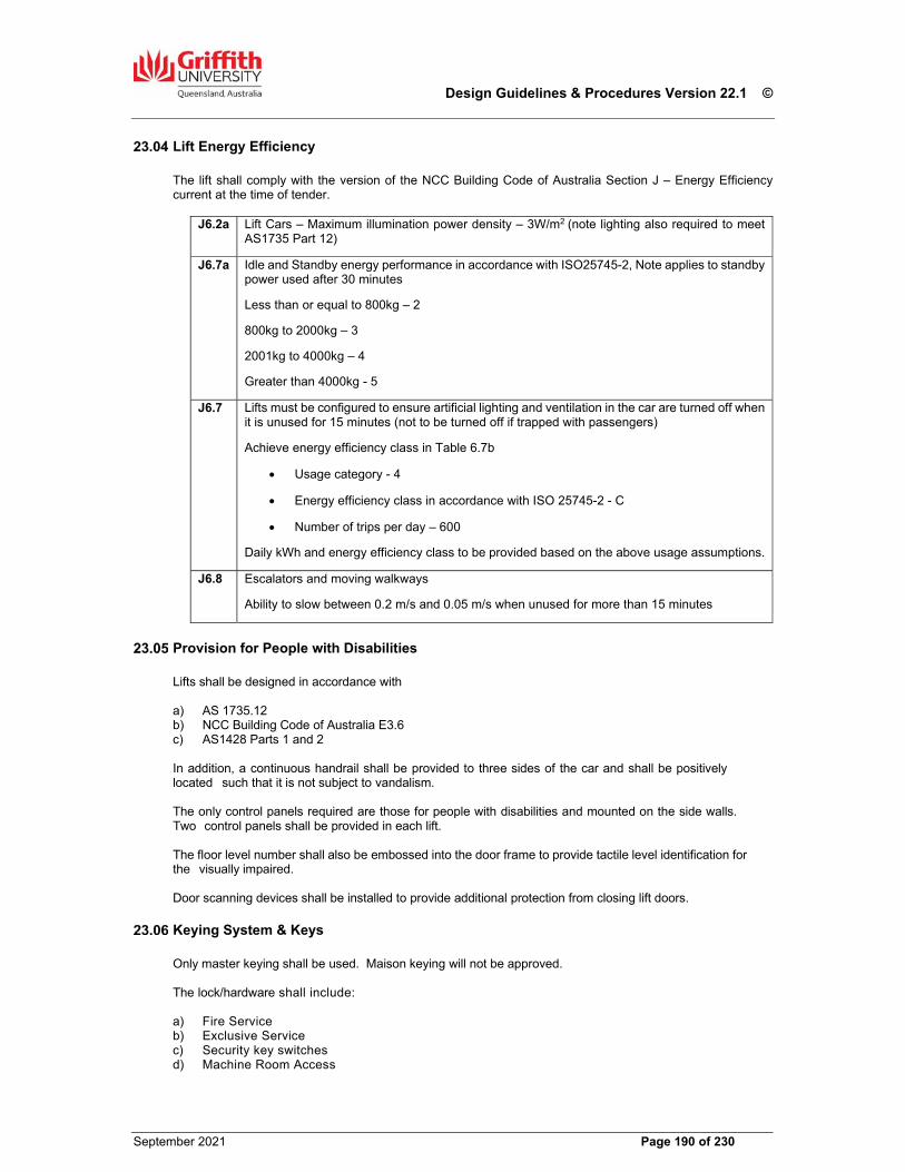
Design Guidelines & Procedures Version 22.1 ©
September 2021 Page 190 of 230
Lift Energy Efficiency The lift shall comply with the version of the NCC Building Code of Australia Section J – Energy Efficiency current at the time of tender.
J6.2a Lift Cars – Maximum illumination power density – 3W/m2 (note lighting also required to meet AS1735 Part 12)
J6.7a Idle and Standby energy performance in accordance with ISO25745-2, Note applies to standby power used after 30 minutes
Less than or equal to 800kg – 2
800kg to 2000kg – 3
2001kg to 4000kg – 4
Greater than 4000kg - 5
J6.7 Lifts must be configured to ensure artificial lighting and ventilation in the car are turned off when it is unused for 15 minutes (not to be turned off if trapped with passengers)
Achieve energy efficiency class in Table 6.7b
Usage category - 4
Energy efficiency class in accordance with ISO 25745-2 - C
Number of trips per day – 600
Daily kWh and energy efficiency class to be provided based on the above usage assumptions.
J6.8 Escalators and moving walkways
Ability to slow between 0.2 m/s and 0.05 m/s when unused for more than 15 minutes
Provision for People with Disabilities
Lifts shall be designed in accordance with a) AS 1735.12 b) NCC Building Code of Australia E3.6 c) AS1428 Parts 1 and 2 In addition, a continuous handrail shall be provided to three sides of the car and shall be positively located such that it is not subject to vandalism. The only control panels required are those for people with disabilities and mounted on the side walls. Two control panels shall be provided in each lift. The floor level number shall also be embossed into the door frame to provide tactile level identification for the visually impaired. Door scanning devices shall be installed to provide additional protection from closing lift doors.
Keying System & Keys Only master keying shall be used. Maison keying will not be approved. The lock/hardware shall include: a) Fire Service b) Exclusive Service c) Security key switches d) Machine Room Access
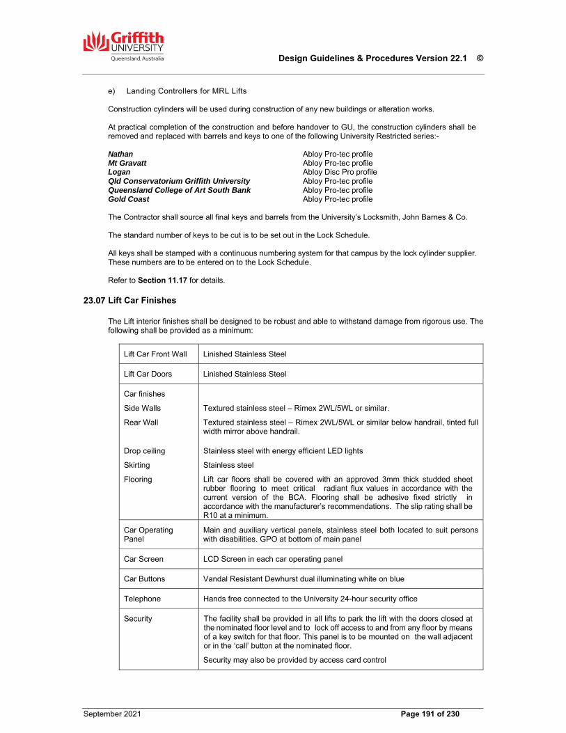
Design Guidelines & Procedures Version 22.1 ©
September 2021 Page 191 of 230
e) Landing Controllers for MRL Lifts Construction cylinders will be used during construction of any new buildings or alteration works. At practical completion of the construction and before handover to GU, the construction cylinders shall be removed and replaced with barrels and keys to one of the following University Restricted series:- Nathan Abloy Pro-tec profile Mt Gravatt Abloy Pro-tec profile Logan Abloy Disc Pro profile Qld Conservatorium Griffith University Abloy Pro-tec profile Queensland College of Art South Bank Abloy Pro-tec profile Gold Coast Abloy Pro-tec profile The Contractor shall source all final keys and barrels from the University’s Locksmith, John Barnes & Co. The standard number of keys to be cut is to be set out in the Lock Schedule. All keys shall be stamped with a continuous numbering system for that campus by the lock cylinder supplier. These numbers are to be entered on to the Lock Schedule. Refer to Section 11.17 for details.
Lift Car Finishes
The Lift interior finishes shall be designed to be robust and able to withstand damage from rigorous use. The following shall be provided as a minimum:
Lift Car Front Wall Linished Stainless Steel
Lift Car Doors Linished Stainless Steel
Car finishes
Side Walls
Rear Wall
Drop ceiling
Skirting
Flooring
Textured stainless steel – Rimex 2WL/5WL or similar.
Textured stainless steel – Rimex 2WL/5WL or similar below handrail, tinted full width mirror above handrail.
Stainless steel with energy efficient LED lights
Stainless steel
Lift car floors shall be covered with an approved 3mm thick studded sheet rubber flooring to meet critical radiant flux values in accordance with the current version of the BCA. Flooring shall be adhesive fixed strictly in accordance with the manufacturer’s recommendations. The slip rating shall be R10 at a minimum.
Car Operating Panel
Main and auxiliary vertical panels, stainless steel both located to suit persons with disabilities. GPO at bottom of main panel
Car Screen LCD Screen in each car operating panel
Car Buttons Vandal Resistant Dewhurst dual illuminating white on blue
Telephone Hands free connected to the University 24-hour security office
Security The facility shall be provided in all lifts to park the lift with the doors closed at the nominated floor level and to lock off access to and from any floor by means of a key switch for that floor. This panel is to be mounted on the wall adjacent or in the ‘call’ button at the nominated floor.
Security may also be provided by access card control
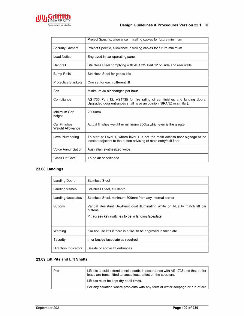
Design Guidelines & Procedures Version 22.1 ©
September 2021 Page 192 of 230
Project Specific, allowance in trailing cables for future minimum
Security Camera Project Specific, allowance in trailing cables for future minimum
Load Notice Engraved in car operating panel
Handrail Stainless Steel complying with AS1735 Part 12 on side and rear walls
Bump Rails Stainless Steel for goods lifts
Protective Blankets One set for each different lift
Fan Minimum 30 air changes per hour
Compliance AS1735 Part 12, AS1735 for fire rating of car finishes and landing doors. Upgraded door entrances shall have an opinion (BRANZ or similar).
Minimum Car height
2300mm
Car Finishes Weight Allowance
Actual finishes weight or minimum 300kg whichever is the greater.
Level Numbering To start at Level 1, where level 1 is not the main access floor signage to be located adjacent to the button advising of main entry/exit floor.
Voice Annunciation Australian synthesized voice
Glass Lift Cars To be air conditioned
Landings
Landing Doors Stainless Steel
Landing frames Stainless Steel, full depth
Landing faceplates Stainless Steel, minimum 500mm from any internal corner
Buttons Vandal Resistant Dewhurst dual illuminating white on blue to match lift car buttons.
Pit access key switches to be in landing faceplate.
Warning “Do not use lifts if there is a fire” to be engraved in faceplate.
Security In or beside faceplate as required
Direction Indicators Beside or above lift entrances
Lift Pits and Lift Shafts
Pits Lift pits should extend to solid earth, in accordance with AS 1735 and that buffer loads are transmitted to cause least effect on the structure.
Lift pits must be kept dry at all times.
For any situation where problems with any form of water seepage or run of are
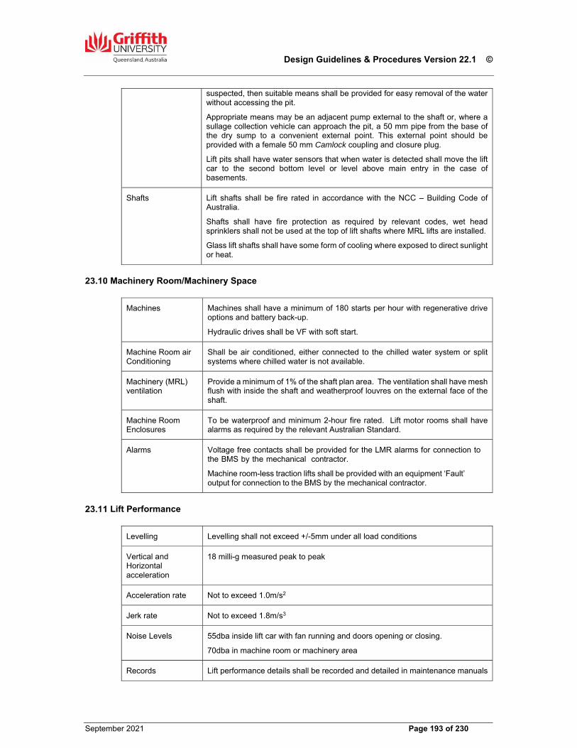
Design Guidelines & Procedures Version 22.1 ©
September 2021 Page 193 of 230
suspected, then suitable means shall be provided for easy removal of the water without accessing the pit.
Appropriate means may be an adjacent pump external to the shaft or, where a sullage collection vehicle can approach the pit, a 50 mm pipe from the base of the dry sump to a convenient external point. This external point should be provided with a female 50 mm Camlock coupling and closure plug.
Lift pits shall have water sensors that when water is detected shall move the lift car to the second bottom level or level above main entry in the case of basements.
Shafts Lift shafts shall be fire rated in accordance with the NCC – Building Code of Australia.
Shafts shall have fire protection as required by relevant codes, wet head sprinklers shall not be used at the top of lift shafts where MRL lifts are installed.
Glass lift shafts shall have some form of cooling where exposed to direct sunlight or heat.
Machinery Room/Machinery Space
Machines Machines shall have a minimum of 180 starts per hour with regenerative drive options and battery back-up.
Hydraulic drives shall be VF with soft start.
Machine Room air Conditioning
Shall be air conditioned, either connected to the chilled water system or split systems where chilled water is not available.
Machinery (MRL) ventilation
Provide a minimum of 1% of the shaft plan area. The ventilation shall have mesh flush with inside the shaft and weatherproof louvres on the external face of the shaft.
Machine Room Enclosures
To be waterproof and minimum 2-hour fire rated. Lift motor rooms shall have alarms as required by the relevant Australian Standard.
Alarms Voltage free contacts shall be provided for the LMR alarms for connection to the BMS by the mechanical contractor.
Machine room-less traction lifts shall be provided with an equipment ‘Fault’ output for connection to the BMS by the mechanical contractor.
Lift Performance
Levelling Levelling shall not exceed +/-5mm under all load conditions
Vertical and Horizontal acceleration
18 milli-g measured peak to peak
Acceleration rate Not to exceed 1.0m/s2
Jerk rate Not to exceed 1.8m/s3
Noise Levels 55dba inside lift car with fan running and doors opening or closing.
70dba in machine room or machinery area
Records Lift performance details shall be recorded and detailed in maintenance manuals
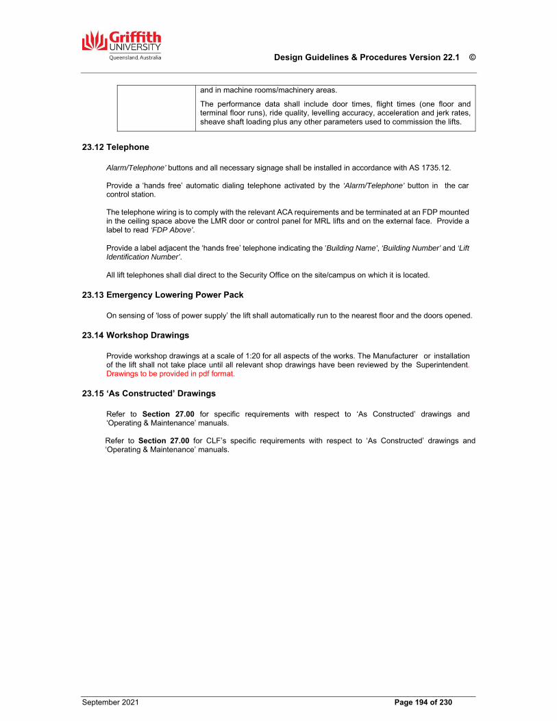
Design Guidelines & Procedures Version 22.1 ©
September 2021 Page 194 of 230
and in machine rooms/machinery areas.
The performance data shall include door times, flight times (one floor and terminal floor runs), ride quality, levelling accuracy, acceleration and jerk rates, sheave shaft loading plus any other parameters used to commission the lifts.
Telephone Alarm/Telephone’ buttons and all necessary signage shall be installed in accordance with AS 1735.12. Provide a ‘hands free’ automatic dialing telephone activated by the ‘Alarm/Telephone’ button in the car control station. The telephone wiring is to comply with the relevant ACA requirements and be terminated at an FDP mounted in the ceiling space above the LMR door or control panel for MRL lifts and on the external face. Provide a label to read ‘FDP Above’. Provide a label adjacent the ‘hands free’ telephone indicating the ‘Building Name’, ‘Building Number’ and ‘Lift Identification Number’. All lift telephones shall dial direct to the Security Office on the site/campus on which it is located.
Emergency Lowering Power Pack On sensing of ‘loss of power supply’ the lift shall automatically run to the nearest floor and the doors opened.
Workshop Drawings Provide workshop drawings at a scale of 1:20 for all aspects of the works. The Manufacturer or installation of the lift shall not take place until all relevant shop drawings have been reviewed by the Superintendent. Drawings to be provided in pdf format.
‘As Constructed’ Drawings Refer to Section 27.00 for specific requirements with respect to ‘As Constructed’ drawings and ‘Operating & Maintenance’ manuals. Refer to Section 27.00 for CLF’s specific requirements with respect to ‘As Constructed’ drawings and ‘Operating & Maintenance’ manuals.
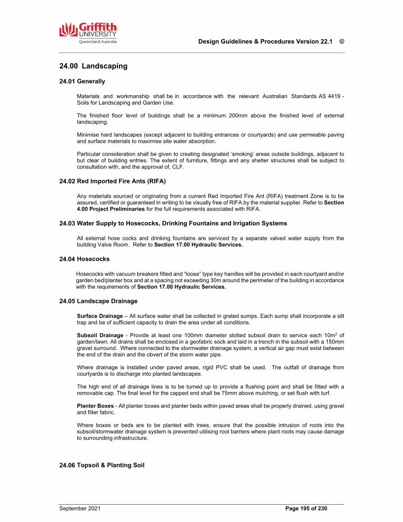
Design Guidelines & Procedures Version 22.1 ©
September 2021 Page 195 of 230
24.00 Landscaping
Generally Materials and workmanship shall be in accordance with the relevant Australian Standards AS 4419 - Soils for Landscaping and Garden Use. The finished floor level of buildings shall be a minimum 200mm above the finished level of external landscaping. Minimise hard landscapes (except adjacent to building entrances or courtyards) and use permeable paving and surface materials to maximise site water absorption. Particular consideration shall be given to creating designated ‘smoking’ areas outside buildings, adjacent to but clear of building entries. The extent of furniture, fittings and any shelter structures shall be subject to consultation with, and the approval of, CLF.
Red Imported Fire Ants (RIFA) Any materials sourced or originating from a current Red Imported Fire Ant (RIFA) treatment Zone is to be assured, certified or guaranteed in writing to be visually free of RIFA by the material supplier. Refer to Section 4.00 Project Preliminaries for the full requirements associated with RIFA.
Water Supply to Hosecocks, Drinking Fountains and Irrigation Systems All external hose cocks and drinking fountains are serviced by a separate valved water supply from the building Valve Room. Refer to Section 17.00 Hydraulic Services.
Hosecocks Hosecocks with vacuum breakers fitted and “loose” type key handles will be provided in each courtyard and/or garden bed/planter box and at a spacing not exceeding 30m around the perimeter of the building in accordance with the requirements of Section 17.00 Hydraulic Services.
Landscape Drainage
Surface Drainage – All surface water shall be collected in grated sumps. Each sump shall incorporate a silt trap and be of sufficient capacity to drain the area under all conditions. Subsoil Drainage - Provide at least one 100mm diameter slotted subsoil drain to service each 10m2 of garden/lawn. All drains shall be enclosed in a geofabric sock and laid in a trench in the subsoil with a 150mm gravel surround. Where connected to the stormwater drainage system, a vertical air gap must exist between the end of the drain and the obvert of the storm water pipe. Where drainage is installed under paved areas, rigid PVC shall be used. The outfall of drainage from courtyards is to discharge into planted landscapes. The high end of all drainage lines is to be turned up to provide a flushing point and shall be fitted with a removable cap. The final level for the capped end shall be 75mm above mulching, or set flush with turf. Planter Boxes - All planter boxes and planter beds within paved areas shall be properly drained, using gravel and filter fabric. Where boxes or beds are to be planted with trees, ensure that the possible intrusion of roots into the subsoil/stormwater drainage system is prevented utilising root barriers where plant roots may cause damage to surrounding infrastructure.
Topsoil & Planting Soil
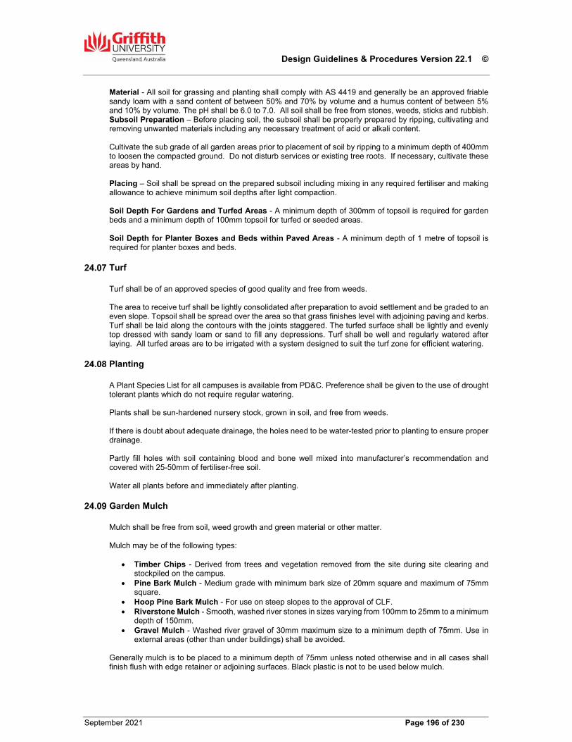
Design Guidelines & Procedures Version 22.1 ©
September 2021 Page 196 of 230
Material - All soil for grassing and planting shall comply with AS 4419 and generally be an approved friable sandy loam with a sand content of between 50% and 70% by volume and a humus content of between 5% and 10% by volume. The pH shall be 6.0 to 7.0. All soil shall be free from stones, weeds, sticks and rubbish. Subsoil Preparation – Before placing soil, the subsoil shall be properly prepared by ripping, cultivating and removing unwanted materials including any necessary treatment of acid or alkali content. Cultivate the sub grade of all garden areas prior to placement of soil by ripping to a minimum depth of 400mm to loosen the compacted ground. Do not disturb services or existing tree roots. If necessary, cultivate these areas by hand. Placing – Soil shall be spread on the prepared subsoil including mixing in any required fertiliser and making allowance to achieve minimum soil depths after light compaction. Soil Depth For Gardens and Turfed Areas - A minimum depth of 300mm of topsoil is required for garden beds and a minimum depth of 100mm topsoil for turfed or seeded areas. Soil Depth for Planter Boxes and Beds within Paved Areas - A minimum depth of 1 metre of topsoil is required for planter boxes and beds.
Turf Turf shall be of an approved species of good quality and free from weeds. The area to receive turf shall be lightly consolidated after preparation to avoid settlement and be graded to an even slope. Topsoil shall be spread over the area so that grass finishes level with adjoining paving and kerbs. Turf shall be laid along the contours with the joints staggered. The turfed surface shall be lightly and evenly top dressed with sandy loam or sand to fill any depressions. Turf shall be well and regularly watered after laying. All turfed areas are to be irrigated with a system designed to suit the turf zone for efficient watering.
Planting A Plant Species List for all campuses is available from PD&C. Preference shall be given to the use of drought tolerant plants which do not require regular watering. Plants shall be sun-hardened nursery stock, grown in soil, and free from weeds. If there is doubt about adequate drainage, the holes need to be water-tested prior to planting to ensure proper drainage. Partly fill holes with soil containing blood and bone well mixed into manufacturer’s recommendation and covered with 25-50mm of fertiliser-free soil. Water all plants before and immediately after planting.
Garden Mulch Mulch shall be free from soil, weed growth and green material or other matter. Mulch may be of the following types:
Timber Chips - Derived from trees and vegetation removed from the site during site clearing and stockpiled on the campus.
Pine Bark Mulch - Medium grade with minimum bark size of 20mm square and maximum of 75mm square.
Hoop Pine Bark Mulch - For use on steep slopes to the approval of CLF. Riverstone Mulch - Smooth, washed river stones in sizes varying from 100mm to 25mm to a minimum
depth of 150mm. Gravel Mulch - Washed river gravel of 30mm maximum size to a minimum depth of 75mm. Use in
external areas (other than under buildings) shall be avoided. Generally mulch is to be placed to a minimum depth of 75mm unless noted otherwise and in all cases shall finish flush with edge retainer or adjoining surfaces. Black plastic is not to be used below mulch.
Design Guidelines & Procedures Version 22.1 ©
September 2021 Page 197 of 230
The selection of the garden mulch type is to be approved by CLF.
Landscape Timber All timber shall be LOSP (Light Organic Solvent Preservative) treated to AS 1604 – 1993 with a minimum stress grade of F5. All timber faces are to receive 2 no. coats of clear water repellent timber preservative after cutting, arising etc. and prior to assembly. All exposed edges are to receive a 5mm wide arris. All fixings to be hot dipped galvanised. Timber edges to gardens are not permitted.
Garden Edges Garden edges to be brown or other approved coloured concrete 100mm wide x 125mm deep, finished with a steel float with arrised edges and construction joints at 1500mm maximum centres.
Retaining & Planter Box Walls Retaining walls to changes in site levels within the landscaped areas may be as follows;
Rock Walls - Rock retaining walls are to be constructed of weathered sandstone or an approved
alternative stone. Walls are to be constructed to an angle of repose of approximately 60o maximum, with all rocks set horizontally into wall face. Install Geotextile filter fabric to rear of rocks.
Concrete Crib Walls - Concrete crib type retaining walls constructed from interlocking precast concrete components and filled with free draining material and earth backfill, all in accordance with the manufacturers’ instructions.
Concrete Block Interlocking Walls - Caps shall be adhered to tops of all walls, and where walls have stepped tops, the caps are to be cut to suit. Installation of walls is to conform to manufacturers’ instructions. Backfill behind wall to depth of 300mm with top soil.
Insitu Concrete Walls – Walls shall be constructed with an approved off form finish. Coloured concrete may be used.
Planter box walls shall generally be constructed in concrete or reinforced concrete masonry. The finish to retaining and planter box walls shall be selected to minimise maintenance. All planter box walls shall be fully tanked, properly drained and water tested prior to placing soil. Tops of retaining and planter box walls shall be designed to eliminate damage from skateboards, roller blades and bicycles. The material, colour and finish of retaining and planter box walls shall be approved by OFM.
Paving & Footpaths In all cases, the finished paving level shall be not less than 200mm below internal floor level or 100mm below damp proof course level, except at entries where paths shall be ramped to doorways to conform to AS 1428.1. Design pavements and locate them in such a manner as to reduce stormwater velocity. The surface of paving should be finished to falls and cross-falls to allow drainage to gardens or grassed areas where possible. Gratings to sumps in courtyards and feature paving shall be stainless steel of a type that is compatible with wheelchair traffic. Paving types may be as follows;
Concrete - Footpaths and general paving may be either exposed aggregate or broom finished and set out with jointing or patterning. The concrete colour should generally be to match any adjoining paving however the use of coloured concrete is desirable. Refer to GU Standard Detail Drawing No. GSD-100 for expansion and contraction joints in concrete paving.
Clay or Concrete Paving Units (including quarry tiles) - Where existing unit paved areas are to be extended or modified, paving units shall be to match existing. If no matching paving units are available,
Design Guidelines & Procedures Version 22.1 ©
September 2021 Page 198 of 230
then consideration shall be given to removing all existing paving units and replacing with an alternative approved by the Superintendent. Refer to Section 6.00 Staircases & Ramps Clause 6.06 for details of permitted tactile indicators in existing paving.
Stone Paving – GU has selected Australian granite as its preferred unit paving for all campuses. The selected stone is ‘Austral Juparana’ in 605 x 300 x 20mm thick units as the main base colour, with ‘Austral Coffee’ in 148 x 148 x 20mm thick units for the contrast features. Examples of the use of this paving can viewed at the Nathan campus in the Campus Heart Plaza and along the Johnson Path pedestrian spine. Black granite/basalt warning and directional tactile pavers 300 x 300 x 25mm thick shall be used in conjunction with all stone paving. The nosing to step treads shall be black in 75 x 20 x 300mm long units with the front edge bevelled to 10mm high to satisfy Code requirements. Pavers on step risers shall have a bevelled top edge to fit the nosing. All paving units, tactile pavers, nosing units and step risers are available from J.H. Wagner & Sons.
Where stone paving is subject to heavy vehicular traffic, the thickness shall be increased to 30mm.
All paving units shall be laid on a reinforced concrete base slab. The thickness of base slabs shall be 100mm min. thick for pedestrian traffic and 150mm. min thick for vehicular traffic areas. Set pavers on a nominal 10mm thickness of mortar bedding, fill joints with matching sand and cement/colour agent and install 10mm thick ‘Ableflex’ to expansion joints in new paving and where new paving abuts existing paths or structures. Provide a concrete haunch along any unsupported edge to paving.
Irrigation System Generally
Garden beds and turfed areas shall not be irrigated unless instructed by the Superintendent. Water for irrigation shall only be taken from the rainwater storage tank provided for the building. If irrigation is required, the Contractor shall supply an irrigation plan before the commencement of the landscaping. The landscape contract must include for the supply, installation, testing and commissioning of all the equipment necessary for the completion of the works described or inferred in the tender specification and drawings. The irrigation system shall be controlled from a Central Controller unit. All necessary approvals must be obtained from the local authorities, Department of Environment and Heritage and other regulatory authorities. The system installer must undertake the commissioning of the irrigation system in the presence of the Superintendent.
Irrigation System Materials & Equipment The irrigation system shall be installed using the following equipment and materials; Water Supply Equipment - Measurable quantities of filtered water at the optimum supply pressure must be provided at the Point of Connection using the following equipment. The equipment must all be flanged drill table D&E.
Filter - ‘Amiad’ or equivalent with 80 mesh filter and a pressure ‘Binda’ cock. Backflow Prevention – ‘RMC‘ or equivalent testable backflow prevention device (on site) to Australian
Standards Control Valves - ‘Irritroll’ either ‘Century’ or ‘Toro 250’ or equivalent. Solenoid Cable - Solenoid cable must consist of polythene insulated multi-strand, multi-core copper
wire in a sheath suitable for direct burial. HTE cable to AS 3147/1988. Cables must run continuously, without joints from controller to converters, valves and switches.
Cable Connectors - Cable joints must be made waterproof and corrosion proof using solder and ‘TYFLO’ Heat shrink, or ‘3 DBY’ or equivalent.
Pipework – All pipework shall be uPVC minimum Class 12 pipe for all main lines, laterals and sub-laterals with solvent welded joints. Class 10 may be used where laterals are down stream from solenoid valves. Sizes
Design Guidelines & Procedures Version 22.1 ©
September 2021 Page 199 of 230
80mm and upward must be rubber ring jointed to AS 1477. MDPE pipe PN 12.5 Class 12 polythene may be substituted for uPVC. Fused joints, or compression fittings must be used, and must have matching pressure ratings. Drip Line – 19mm dia. standard uPVC pipe as nominated above perforated as required to suit the application. Pipe Fittings - Galvanized or black iron fittings or pipe must not be used. uPVC pipe fittings must be Class 18 and complying with AS 1477, and must be made by the same manufacturer as the PVC pipe. MDPE pipe fittings must be ‘Philmac’ or equivalent. Screwed fittings must be ‘Philmac’ or equivalent with tapered threads. Drip tape fittings must be ‘Wingfield’. Fittings selection and use should be as follows:
Item Fittings DescriptionsuPVC Pipe, bends Cat P12 rubber ring long radius fittings
uPVC Pipe 50mm uPVC fittings
uPVC Mainline to control valves Screwed bronze tapping saddles
MDPE Pipe to sprinklers Plastic tapping saddles complete with 4 stainless steel bolts and stainless steel reinforcing rings; Plasson or equivalent
uPVC Mainline to Air Valves Screwed bronze tapping saddles with valve sized outlet mounted vertically, Philmac nipples to ball valve and air valve
uPVC termination uPVC rubber ring end cap and concrete thrust block Sprinklers - Spray heads must be Toro, Hardie or approved equivalent. Use 12” Pop-up for shrubs and 6” Pop-up for ground covers. Sprinkler heads shall be as follows;
Small Rotor Heads - ‘Toro 300’ series. Small Spray Heads – ‘Toro 570’ series Large Rotor Heads – ‘Toro 640’ series. Pop-up Sprinklers – ‘Spears’ on articulated risers sized to match the sprinkler inlet size.
Valves – Valves shall be as follows;
Air Valves – ‘Bermad’ 25 and 50mm double purpose air release model 4415 or equivalent. Isolating Valves – Refer to Section 12.00 Hydraulic Services Valve Boxes - Must be made of structural foam and must be fitted with locking lids. Valve boxes for
control valves must be Carson 910 or equal. Other boxes must be large enough to house, and allow service of, their valves.
Irrigation System Installation Controller – The controller must be hard wired to a dedicated circuit breaker and must be identified at fuse box as being ‘Irrigation Only’. Water Meter and Pressure Regulating Valve – This shall be installed as a single assembly, comprising filter, water meter, pressure regulating valve and backflow device in accordance with current AS 3500 and associated codes. The assembly connections are to be dezincified brass with inlet/outlet isolation ball valves. The assembly must be supported by a hot dipped galvanized mild steel stand and be contained within a lockable, purpose made, galvanized box.
Design Guidelines & Procedures Version 22.1 ©
September 2021 Page 200 of 230
Rain Sensor – A Rain Sensor 'Mini-Click™ ' or ‘Toro’ with a ‘Irritrol’ Code 2595 Moisture Sensor Override is to be installed on each system aesthetically positioned in a location safe from vandals, and where rain will always fall on it. If the sensor must be on a field post see sample at Nathan Oval No. 1. Sprinklers - Sprinkler positions must be set out by a certified irrigation designer with a minimum of head to head spacings. Shrub sprinklers must be installed on risers. Pop-up sprinkler risers must be installed allow free movement of the sprinkler before backfilling, and sprinklers shall be set to grade. Control valves with flow control must all be adjusted to provide optimum sprinkler performance without misting or overthrow. Drip Lines - Installation must commence at the control valve where the 20mm, 200 mesh filter and air vent are fitted. The 40mm MDPE sub main is to be connected to a pressure regulating valve with 68 kPa discharge pressure, and at each group of two or three lines. The pressure reducing valve is connected to the line by 19mm Polythene pipe. The drip line must be buried 75mm below ground level and must be laid in row spacings of 600mm. Control Valves - Control valves must be identified by permanent engraved labels securely fastened to the valve flow stem. Valve boxes must be set to grade with the base supported on bricks to ensure there can be no contact with irrigation pipe works. Excavation & Backfilling - The system installer must not excavate by machine within 1 metre of existing underground services. All surfaces (turf, concrete, bitumen etc) and any existing underground services damaged or cut as a result of excavations by the installer must be restored to their original condition. Trench widths must be equivalent to 3 nominal pipe diameters to provide working room and to ensure ample sand bedding all round the pipes. Trench depths must be sufficient to allow 75mm of sand underlay under the pipe, + the pipe diameter of pipe + 150mm sand + 150mm of topsoil. The trench bottom must be level, free of rocks and sharp objects and must support the whole length of the pipe. Backfilling to trenches for all pipes, and cables and conduits shall be screened bedding sand. The minimum underlay shall be 75mm and the minimum overlay 150mm. Install pipe marker tape over sand before backfilling with top soil. Suitable spoil from the trench excavation, free from rocks, clay, rubbish and building debris may be used to top up the trench if necessary. Where separate trenching is needed for the power or communication cable, the minimum depth must be 450mm and minimum width 100mm. Pipelaying - PVC pipe must be installed to conform with the current AS 2032. MDPE pipe must be installed to current AS 2033 and AS 1460 parts 1 & 2. Care must be taken not to kink pipe. Control Wiring - Control wire (24V AC) must be run continuously without joins from each pilot valve to the Controller. The common and actives must be taped together at 1 metre intervals and laid in a trench on the sand bedding beside the pipe. Wires must be laid loosely in the trench, with a 300mm loop at each valve connection and at each change of direction, so that they are not under tension when the trench is backfilled. Any exposed wire or installation below concrete must be installed in grey conduit.
Design Guidelines & Procedures Version 22.1 ©
September 2021 Page 201 of 230
All solenoid cables must be tested for electrical conductivity to ensure no leaks to earth or other faults occur. Any problems must be fixed prior to connection to the controller. Flushing of New Pipework - After pressure testing has been carried out the new pipework must be flushed thoroughly with the available water pressure before the sprinklers are attached to the risers. Hydraulic Testing - The whole of the system must be tested at 1000 kPa. The tests must be carried out by the installer at his own risk and expense. All work shall withstand the test pressure for a period of two hours. Thrust Blocks - Thrust blocks are required on all rubber ring jointed pipe, uPVC pipe sizes 80mm and above and Poly pipe 100mm and above or where fabricated fittings are used AS 3500. Thrust blocks shall must be placed at all tees, and bends, (whether horizontal or vertical), and blank ends and changes in diameter or direction, or where it is expected to develop thrust eg. valves or in unstable soil conditions. in rubber ring jointed pipe. Ductile iron isolating valves must be tied down to thrust blocks by galvanised iron straps using galvanised bolts. Thrust blocks must be placed so that pipe and fittings will be accessible for repair. Thrust blocks must not be covered until they have been inspected by the Superintendent. Restoration of Existing Surfaces - All existing surfaces, concrete, turf, or bitumen where disturbed by the system installation shall be restored by the installer unless otherwise advised by the Superintendent. Warranty – The Contractor must provide a warranty on workmanship for a period of twelve (12) months after the date of Practical Completion to GU. As Constructed Drawings - As constructed drawings of the irrigation system shall be submitted according to requirements in Section 27.00. All piping, wiring and major components must be shown using triangulation from at least two fixed ground permanent points and/or surveyed. Provide a list of components and show typical layouts and fittings.
Landscape Furniture The selection of landscape furniture including seats, bins, bollards, lighting, fencing and signs is to be to the approval of CLF. In all cases, consideration is to be given to matching existing adjacent furniture or that which is generally adopted for use on the particular campus. Drinking fountains in external landscaped areas shall be ‘Street & Garden Furniture Co.’ FL100 cast aluminium fountains with selected powdercoat finish. Fountains shall be securely fixed to concrete slabs or pad footing in accordance with the manufacturer’s instructions, and waste water disposal shall be to the approval of CLF. Furniture on the Nathan campus shall be in accordance with the Furniture Catalogue developed from the Nathan Master Plan. This catalogue is available from the CLF Senior Architect, who shall be consulted on the type and colours of furniture items to be incorporated into the Landscape design.
Supervision of Landscaping Work The Landscaping Design Consultant shall be responsible for the supervision of all landscaping works carried out in accordance with its specification and drawings and these Guidelines and Procedures. The Design Consultant shall submit a report on the completion of the works certifying that the work has been completed to the satisfaction of the Consultant and in compliance with all the above mentioned documentation.
The Landscape Maintenance Period The Landscape Maintenance period shall commence from the date of Practical Completion of the Works and shall extend for a period of twelve (12) months. Maintenance of landscape works to include watering, mowing,
Design Guidelines & Procedures Version 22.1 ©
September 2021 Page 202 of 230
pruning, weeding, fertilising, pest and disease control, replacement of dead or missing plants and the like for grassed and garden areas. Any replacement plants shall be of a size and maturity which matches those in the landscaping at the time of replacement.
External Signage
All external signage shall be in accordance with the GU Signage Manual. The CLF Senior Architect shall be consulted on the type and location of all signage units.
Design Guidelines & Procedures Version 22.1 ©
September 2021 Page 203 of 230
25.00 Signage
The requirements of this Section are Mandatory.
Generally
The University has adopted a new suite of standard signs to be used across all its campuses. All sign types are illustrated in the Griffith University Signage Manual together with any Pending Amendments to that Manual, which are published on the University website at the following address GU Signage. In conjunction with this Manual, CLF is preparing a series of Standard Drawings for the fabrication and installation of all signs which are not ‘flat plate’ or fabricated from proprietary components. The current list of Standard Drawings is provided later in this Section.
Responsibilities of Design Consultants for Signage Unless otherwise advised by CLF, the project Architect is responsible for the preparation of documentation required for the procurement and installation of all project signage, both internal and external, which shall be included in the tender documents. This documentation shall be based on the Signage Proposal example and Signage Schedule template documents published on the foregoing web address. The text to be included on each sign type will be provided to the architect by the CLF Project Manager following consultation with and input from the project User Coordinator or principal User.
Departures from the Signage Manual There shall be no departures from the design and use of the signage types, colours and graphics nominated in the Signage Manual. Any proposal to depart from the Manual’s requirements must be submitted to CLF for consideration and approval.
Statutory Signage All statutory signage required for a project shall be provided as part of the Contract Works. The project Architect in conjunction with the other design consultants is responsible to determine all statutory signage requirements in accordance with the BCA, Australian Standards or relevant legislation. Statutory signage also includes all hazard identification and safety signage associated with laboratories and other specialist areas. These requirements shall be confirmed with the relevant Group/School/Research Centre WH&S officers.
Braille and Tactile Signage Braille and tactile signage shall be provided in accordance with the requirements of the BCA and the recommendations of the GU Access Consultant. Braille and tactile elements are a mandatory requirement for the following signage types;
Internal room identification Facility entrance identification Public directory information
Special Signage The use of special signage to the reception area or counter for Groups, Schools, Research Centres or Departments to identify and portray the unique nature or function of that facility including logos, non standard text fonts or illumination, is permissible. Such signage shall be designed by the project architect or interior designer in consultation with CLF and the Users. In designing and locating special signage, consideration must be given to the future removal or modification of the signage without causing significant damage to wall, bulkhead or ceiling surfaces and finishes.
Design Guidelines & Procedures Version 22.1 ©
September 2021 Page 204 of 230
The use of the Griffith University logo in signage elements, must be referred to the Office of Marketing & Communication for their review and approval to ensure compliance with the GU Identity Manual. Signage for commercial tenancies will normally be the responsibility of the tenant/operator, subject to the approval of CLF.
Standard Signage Drawings Standard Drawings (GSS Series) have been prepared by CLF which are applicable to the following sign types;
Building Identification sign –freestanding Pedestrian directional sign – freestanding Site directory information sign – freestanding Identity sign – projecting Directional sign – suspended
These drawings are under regular review and the current revision will be provided by the PD&C Senior Architect on request. Drawings for other sign types will be developed progressively and made available when completed.
Design Guidelines & Procedures Version 22.1 ©
September 2021 Page 205 of 230
26.00 Loose Furniture & Equipment
Generally Unless otherwise noted on the SDFs, all loose furniture and equipment shall be supplied and installed by GU under a separate contract to the main building contract. Furniture (e.g. chairs, seats, work stations, tables etc.) is generally to be of a quality suitable for ‘heavy duty commercial’ use, with a minimum warranty of five (5) years. The Head Consultant or Contractor shall prepare a furniture layout drawing and a ‘Colours & Finishes Board’ which includes the furniture finishes for presentation to CLF. User requirements for furniture types shall be described in the project Space Description Forms. Furniture purchased shall comply with the specifications contained in the Furniture Catalogue prepared by CLF. This catalogue is located on the Griffith Portal which is accessible only to GU employees, however the relevant specifications will be made available to Consultants and Contractors on written application to the Associate Director, Minor Projects (PD&C) CLF.
Specialist Furniture In some areas (e.g. executive areas, areas requiring a corporate image, Research Centres, Learning Centres, Laboratories, Cafes etc.) ‘specialist’ furniture, other than that described on the web page may be required. Selections are to be approved by CLF.
Furniture Suppliers Furniture shall be purchased only from suppliers approved by CLF and who are pre-qualified under the Queensland Government State Purchasing Policy (QGSPP) to supply furniture to Queensland Government Departments and other entities who fall under the jurisdiction of the QGSPP. For any other suppliers, competitive quoting procedures (in accordance with the QGSPP) will apply. Current acceptable suppliers and suppliers previously used by the University, are listed on the CLF web page.
Timber Furniture Requirements Timber furniture includes items manufactured from timber or melamine veneered MDF board and metal, such as office work stations (GU Standard Detail Drawing GSD-407), mobile drawer units (GU Standard Detail Drawing GSD-408), tables, trolleys, etc. MDF board used in furniture items shall be ‘E Zero’ board, and the selection of all materials used shall comply with the requirements of Section 3.00 Designing for Sustainability. Furniture shall generally be finished in Laminex Select ‘Beech’ melamine with matching 2mm ABS edging. In some circumstances graded Tasmanian Oak veneer with matching 2mm solid flat and arrised edging. All Tasmanian Oak veneer and edging shall be GECA, FSC and AFS/PEFC certified. All large meeting tables are to have a Laminex Select ‘Beech’ melamine finish. Melamine finishes to computer benches shall as approved by CLF. Work surfaces (e.g. work stations, desks, computer benches) shall be 720mm above finished floor level, unless otherwise required. Generally, horizontal timber spans (>800mm) and gable supports shall be 25mm thick, with other vertical panels 18mm thick. SHS metal framing and legs shall have 2mm minimum thick walls with a black powder coated finish, and the foot of each leg shall be fitted with a black plastic slide.
Design Guidelines & Procedures Version 22.1 ©
September 2021 Page 206 of 230
Chairs This clause provides requirements for task chairs, visitor chairs, meeting chairs, seminar chairs, waiting chairs etc. Chairs selected for general use must be available for a minimum of five years so replacements can be purchased. All office task chairs and chairs used for computers are to be fully ergonomic gas lift chairs on castors. Office task chairs shall have adjustable backs, and seat and back tilt. Arms are not recommended. Chairs with adjustable lumbar support to backs, adjustable arms and large seats and backs will be supplied to individuals if required (requirement to be confirmed by CLF). Chairs, including fabrics, will generally be suitable for ‘heavy-duty commercial’ use. Ergonomic task chairs will have a ‘Furntech/AFDI’ Level 6 certificate of assessment. Upholstery fabrics shall be selected to disguise stains, therefore light colours are to be avoided. Patterns and/or textures are preferable. Preference is to be given to fabrics where the fibre is produced from a recyclable or renewable resource. Acceptable fabrics are nominated in the ‘Furniture Standards’ on the CLF web page. Chair arms are not to be fabric-upholstered. Chairs used in teaching areas will not be fully upholstered, but upholstered seat and back pads may be used. Visitor, waiting and lounge chairs shall be selected in consultation with and to the approval of CLF.
Seminar Room Furniture Tables shall be a general purpose type 600 x 1200mm, and two (2) shall be adjustable for wheelchair use. Chairs to Seminar/Tutorial Rooms shall be ‘Sebel Progress’ polypropylene stackable chairs (no upholstery) in standard colours.
Learning Centre Furniture The selection and colours for Learning Centre furniture shall be coordinated with the overall design, and in consultation with CLF. Loose tables to the Open Access Computer Work Area shall be selected or designed to suit the overall style and theme of the ‘built-in’ fittings. Tables for Group Study Spaces shall be similar to Seminar Rooms. All chairs other than computer chairs shall be stackable partly upholstered chairs.
External Furniture External furniture may be loose if the area is secured, otherwise it shall be fixed. External furniture shall generally be limited to tables and chairs or benches. Chairs shall be anodised aluminium or UV stable polypropylene, and shall be self-draining. Table tops shall be resistant to water, heat, abrasion, cigarette burn and UV light. Framing to tables and chairs shall be welded and not screw fixed.

Design Guidelines & Procedures Version 22.1 ©
September 2021 Page 207 of 230
Metal Furniture Metal furniture shall comprise filing cabinets (2, 3 or 4 drawer), storage cupboards, shelving units or lockers. All metal furniture shall have a powdercoat finish with minimum five (5) year warranty for both furniture and finish.
Design Guidelines & Procedures Version 22.1 ©
September 2021 Page 208 of 230
27.00 Post Construction Responsibilities of Consultants & Contractors All the requirements of this Section are Mandatory.
Generally This Section deals with the responsibilities for Consultants and Contractors with respect to the provision of ‘As Constructed’ drawings, Maintenance Manuals and Survey information to the Superintendent, as well as the GU requirements with respect to the performance of preventative maintenance during the Defects Liability Period. The responsibility for providing the necessary documentation for projects delivered under ‘Traditional’ Lump Sum contracts shall be with the Design Consultants. In the case of projects delivered under Design & Construct contracts, the responsibility shall be with the D&C Manager.
Preventative Maintenance All GU Contracts require the performance of regular preventive maintenance and servicing of the works during the Defects Liability Period. Such maintenance shall be in accordance with the manufacturer’s instructions and the requirements of the Workplace Health and Safety Act, Standards or other applicable regulations, legislation or codes of practice. With respect to any mechanical or electrical service, fire alarms, hydraulic systems, lifts etc. maintenance shall be carried out not less frequently than monthly. At least one month prior to achieving Practical Completion, the Contractor shall prepare and provide a Program to the Superintendent which indicates all Preventative and Statutory Maintenance work to be undertaken during the Defects Liability period including nominating the company/person who will undertake the maintenance work and the time frame (month/year) on which it will be carried out. A written report including copies of Logbooks and maintenance records shall be provided to the Superintendent immediately after each monthly service is performed. The report shall detail all work done, defects identified and repaired, and general comments on overall performance. The Certificate of Final Completion will not be issued until such time as all preventive and statutory maintenance requirements have been completed, including the final service at the of the defects liability period, and all Log Books and maintenance records have been provided to the Superintendent.
Guarantees & Warranties The Contractor must provide guarantees, test and similar certificates as specified under the various trades as soon as reasonably possible after the granting of Practical Completion and before the issue of the Certificate of Final Completion. The Contractor must ensure that such guarantees and certificates have been effectively transferred or issued to the Principal so that thereafter the Guarantor must be directly responsible to the Principal commencing from the date of Practical Completion. Written warranties in respect of Windows, Roofs and Applied Finishes shall be for not less than ten (10) years. Refer to Section 14.00 Clause 14.02 for warranty requirements with respect to mineral fibre tile suspended ceiling systems.
Operating & Maintenance Manuals Operating and Maintenance (O&M) manuals shall cover all aspects of the work undertaken in the project. All Manuals shall have a Cover page providing the key project information as required by Standard Drawing GSD-001D. Each Manual shall have a Contents page properly structured into Sections and indexed with page numbers. The manuals shall be submitted to the Superintendent in electronic format, and they shall be grouped into a single PDF file for each discipline corresponding to the list provided on Standard Drawing GSD-001C. The PDF file shall be fully searchable and bookmarked according to the section index. Refer to Section 32.00 for an Operating & Maintenance Manual template. A PDF file of this template shall be requested from and provided by the Superintendent. All PDF files shall be unlocked, and not secured or restricted in any form.
Design Guidelines & Procedures Version 22.1 ©
September 2021 Page 209 of 230
The O&M manuals shall include but not be limited to the following; A general description of the scope of the project A list of all design consultants employed on the project whether by the Principal or the Contractor Details of all suppliers and subcontractors supplying goods or services to the project Finishes and colour identification schedules Operating instructions and technical schedules for all equipment and plant installed as component
parts of the project Maintenance instructions including time schedules Control system and electrical layout plans complete with terminal numbers corresponding to wiring
ferrules, with cross referencing as necessary Testing and commissioning dates, set points, flow rates, timer settings etc. including all testing
evidence certificates An asset list of all maintainable equipment (CLF will provide a template which must be completed in
full) All warranties and guarantees All statutory certificates and approvals
‘As Constructed’ Drawings
Prior to Practical Completion, the Consultants or Contractor shall submit a proposed Schedule of ‘As Constructed Drawings’ for approval by the Superintendent. The Schedule shall comprise a full list of ‘As Constructed’ drawings for the project, with all key information on the drawing noted and including the corresponding electronic drawing file name for each drawing. The Consultants or Contractor shall submit the ‘As Constructed’ drawings in accordance with the approved Schedule. Failure to provide ‘As Constructed’ drawings in accordance with the Schedule will result in the Superintendent withholding funds from progress payments sufficient to cover the cost of preparing the documents by other means. Where drawings are sourced from Subcontractors e.g. shop drawings, for ‘As Constructed’ drawings, the Consultant or Contractor shall check to ensure that these drawings comply fully with these Design Guidelines & Procedures, before submitting them to the Superintendent. The ‘As Constructed’ drawings shall clearly describe all works carried out in the Contract showing both concealed and exposed items, be fully dimensioned and contain at least the following information:
All equipment and system identification All regulating and measuring devices in the system Final accepted values of commissioning data (e.g. air/water flow quantities, voltage/current, signal
strength etc.) Final settings of all regulating devices Major equipment maintenance/servicing access clearance requirements
The scope of ‘As Constructed Drawings’ shall include as a minimum the following drawings provided:
Discipline Minimum Content of Drawings
General site information All in-ground services reticulation and external installation including electrical, lighting, fire hydrants, sewerage, water, stormwater, chilled water, gases, communications and data.
Connection details to existing infrastructure and invert levels of gravity fall pipework.
Site & Building location
Architectural All floor plans and partition layout plans
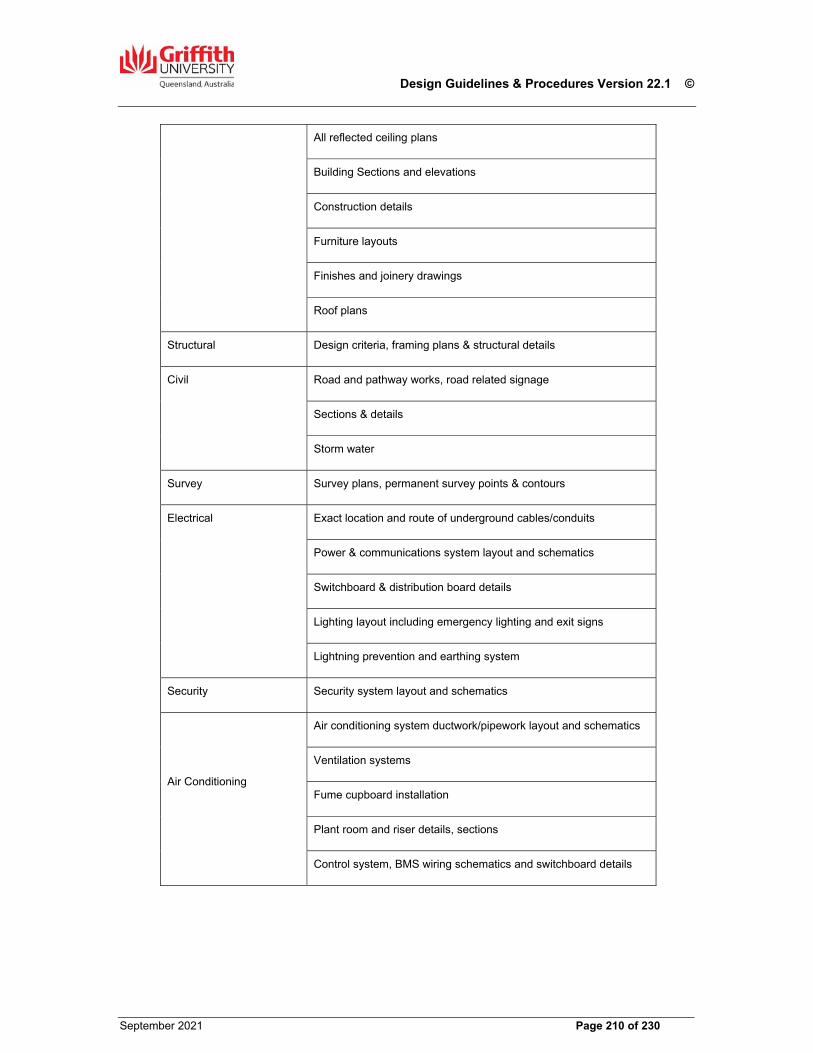
Design Guidelines & Procedures Version 22.1 ©
September 2021 Page 210 of 230
All reflected ceiling plans
Building Sections and elevations
Construction details
Furniture layouts
Finishes and joinery drawings
Roof plans
Structural Design criteria, framing plans & structural details
Civil Road and pathway works, road related signage
Sections & details
Storm water
Survey Survey plans, permanent survey points & contours
Electrical Exact location and route of underground cables/conduits
Power & communications system layout and schematics
Switchboard & distribution board details
Lighting layout including emergency lighting and exit signs
Lightning prevention and earthing system
Security Security system layout and schematics
Air Conditioning
Air conditioning system ductwork/pipework layout and schematics
Ventilation systems
Fume cupboard installation
Plant room and riser details, sections
Control system, BMS wiring schematics and switchboard details
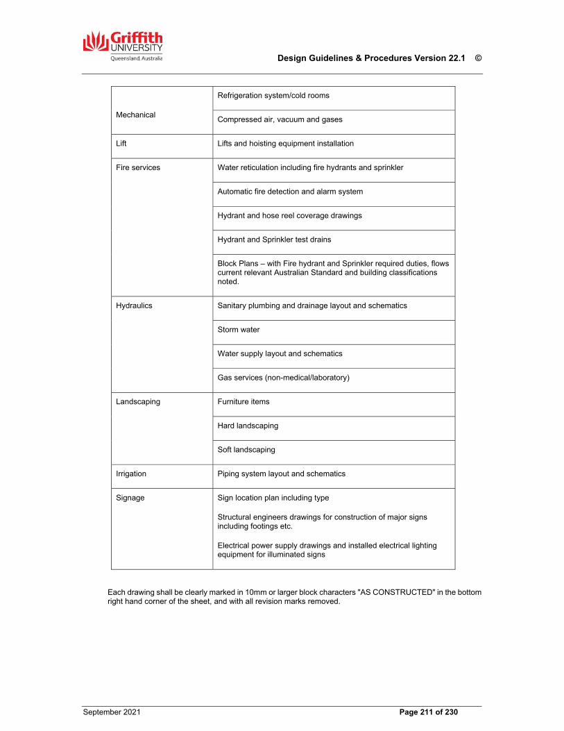
Design Guidelines & Procedures Version 22.1 ©
September 2021 Page 211 of 230
Mechanical
Refrigeration system/cold rooms
Compressed air, vacuum and gases
Lift Lifts and hoisting equipment installation
Fire services Water reticulation including fire hydrants and sprinkler
Automatic fire detection and alarm system
Hydrant and hose reel coverage drawings
Hydrant and Sprinkler test drains
Block Plans – with Fire hydrant and Sprinkler required duties, flows current relevant Australian Standard and building classifications noted.
Hydraulics Sanitary plumbing and drainage layout and schematics
Storm water
Water supply layout and schematics
Gas services (non-medical/laboratory)
Landscaping Furniture items
Hard landscaping
Soft landscaping
Irrigation Piping system layout and schematics
Signage Sign location plan including type
Structural engineers drawings for construction of major signs including footings etc.
Electrical power supply drawings and installed electrical lighting equipment for illuminated signs
Each drawing shall be clearly marked in 10mm or larger block characters "AS CONSTRUCTED" in the bottom right hand corner of the sheet, and with all revision marks removed.
Design Guidelines & Procedures Version 22.1 ©
September 2021 Page 212 of 230
Post Construction Site Survey
The Contractor shall provide a Post Construction Site Survey for any contract involving new buildings and extensions to existing buildings, within four weeks of the date of Practical Completion. All survey work must be carried out by a competent, registered Surveyor. The new post construction survey undertaken must relate to the original site survey provided to the Consultant/Contractor by the Principal, and shall be merged, aligned and presented in layers which correspond with the overall existing campus CAD file survey record.
The survey shall achieve the following;
Topographical survey of all areas affected by the construction work in this contract showing the ground level contours at 0.25m (maximum) intervals based on Australian Height Datum (AHD).
The site survey shall be on Map Grid of Australia 1994 (MGA94) grid coordinates and shall also be referenced to at least one existing Permanent Survey Mark (PSM) within the campus concerned.
The exact footprint of the new building, or extension to existing building, in relation to existing buildings in the immediate vicinity.
Provide invert and surface levels of pits and underground services including changes of direction Provide all pipe sizes of underground pipes Provide location of all underground services including co-ordinates
The following details are to be shown;
In-ground data and electrical reticulation, including all data and electrical pits. Sewer and stormwater reticulation, including pipe sizes and location of all access/inspection chambers. Water and fire main reticulation, isolation valves, including all fire hydrants and booster pumps. Chilled water reticulation, including location of pits and isolation valves. All paths and roads constructed as part of the contract, tied into existing site surveys provided by the
principal. All external path and road lighting, provided under the contract. Location and size of drains, columns, poles, sign posts, overhead structures, planters, steps, ramps
and retaining walls Ground line markings for car parks and traffic, traffic islands, boom gates and traffic lights All building entry locations and levels All trees with a girth greater than 200mm measured at one (1) meter above surrounding ground level
and exposed rocks greater than one (1) meter in any one dimension which occur within ten (10) meters of the building footprint
Any other permanent site features Underground Services shall be surveyed for line and level prior to backfilling
The Post Construction Site Survey Plans shall meet the requirements for ‘As Constructed’ Drawings outlined in Clause 27.05 of this Section.
Permanent Survey Marks The Contractor’s surveyor must supply and install a Permanent Survey Mark (PSM) in the form of a brass plaque, set into a concrete path, pavement or kerb external to the building, in a location determined by the Superintendent. The surveyor shall also register the PSM with the Department of Environment & Resource Management, on a ‘Form 6 - Permanent Mark Sketch Plan’ in accordance with the requirements of the Survey and Mapping Infrastructure Act 2003. A copy of the Form 6 shall be provided to GU.
Design Guidelines & Procedures Version 22.1 ©
September 2021 Page 213 of 230
28.00 Project Briefing & Procurement
Generally A new building marks a significant investment in the future of the University. For many years hence it will reflect the changing role of the University in ongoing learning, research and community service. It is likely that each new building will have a life of up to forty (40) years, and so, by its very nature a building is a strategic investment. A new building will need to adequately cater for the needs of several future generations of students, staff and academic styles. It is important that the design of each new building is based on a well developed understanding of the future direction of the community, Griffith University, our region and the changing nature of the professions and academic disciplines that are to be housed in it. The purpose of this Section is to outline the processes and procedures for developing the Project Design Brief for a new building, and for procuring the project in accordance with that Brief. The Project Design Brief comprises two elements, the Strategic Objective Brief and the Technical Brief, the details of which are outlined in the clauses of this Section. Prior to a Capital Works project being undertaken by GU, the Project Design Brief must be developed to enable suitable Architects and Contractors to submit proposals for the design only, or the design and construction of the proposed facility. The procedures for the planning, design, documentation and construction of GU’s Capital Works, is represented in this Section Schematic form.
The Strategic Objective Brief The aims of the Strategic Objective Brief are as follows;
to ensure that the design of the proposed new building is related to clearly stated University and academic objectives;
to maximise the return on the investment in built assets by ensuring the future appropriateness of the new building; and
to give guidance and direction to the design of the new facility through a structured design brief that respects and reflects current academic and community trends.
The Brief will be developed, with the assistance of CLF, by the Academic Group/s having ultimate responsibility for the staff and/or functions to be housed in the proposed building. The preparation of this Brief enables the intended building users to have an opportunity to specify the strategic intent of the new building, and to systematically develop a building concept which realises that objective. Once this Brief has been reviewed and agreed to by the Group PVC/s and senior executives of the University if appropriate, the Brief will be circulated to members of the Project User Committee (PUC) for comment with a view to the formal ratification of the Brief at the first scheduled PUC meeting.
Structure & Content of the Strategic Objective Brief The Strategic Objective Brief will comprise two specific sections. Each section will address a key objective for the project as follows;
Overview and Purpose - to provide a structured outline of the strategic and academic intent of the proposed building according to four main sub-headings.
Design Intent - to provide guideline as to how the strategic and academic intent of the proposed building might be reflected in its design to realise the User’s specific requirements and expectations
Design Guidelines & Procedures Version 22.1 ©
September 2021 Page 214 of 230
Overview & Purpose This section contains four specific topics to be considered in context by the Users to demonstrate how the proposed building will achieve the strategic goals and functional requirements of the University. These topics are as follows;
University context Community context Campus context Academic context
In considering each topic, the Users are presented with an opportunity to explore and elaborate on the role that the new or refurbished building will play in the context of meeting the strategic development goals of the University and its campuses, the enhancement of engagement with both the University and the wider communities, and the expansion and improvement in the delivery of academic programs. University Context - This topic will explain how the proposed new or refurbished building is intended to meet the Vision and Mission of Griffith University. It should cover the key principles of excellence and innovation in teaching, research and community services and specifically if and whether these principles are integral to the academic function and design of the proposed building. This explanation will demonstrate how the building will enhance the following goals of the University to;
maintain and enhance its position as the dominant provider of tertiary education in the Brisbane-Gold
Coast corridor provide a national model for innovative teaching and learning through bringing disciplines together establish Itself as a major research-based University with international recognition of expertise in key
areas of research strength; develop best practice in ensuring equitable and effective environments for students and staff consolidate a series of key strategic alliances to develop a network of service provision in teaching
and information services Community Context - This topic will explain the role of the building and its functions in the community, and should address the following issues;
will the building serve broader University community needs? how will it relate to other professional or academic institutions? how will the University and wider community interact with the building? who in the University and wider community will interact with the building?
Campus Context – This topic will include an explanation of the selected campus and building location within that campus and why this is the case. Consideration may be given to briefly cover any other options that have been or should be considered (e.g. off-campus location, cross-campus operations). The importance or necessity of a specific location in terms of the identified demand or critical relationship with a specific campus zone or other buildings is explained. Academic Context - This topic elaborates on the aspects of the building that are critical to the academic, research and community objectives of the specific elements (Group, School, Centre, Department) that are to be housed in the proposed building. It provides a description of the academic and working environment to be created in the new building by considering each of the following aspects or requirements to be catered for in the proposed building;
Teaching Flexible Learning Research Day to day functionality Number, type, size and mix of the elements e.g. Academic Research and General Staff
Administration, special teaching or research spaces Organisational structure Explanation of the likely future direction, expansion or change anticipated within the elements over
the short to medium term after occupation.
Design Guidelines & Procedures Version 22.1 ©
September 2021 Page 215 of 230
Design Intent This section contains three topics to guide Consultants and Users in developing their concept of the new building. In ‘Design Intent’, users have an opportunity to elaborate on the role of the proposed new building in realising the issues covered in the ‘Overview and Purpose’ section of the Brief. The three topics to be used as guidelines to cover design issues are; Building Concept - This topic is intended to focus on the building itself and provide an opportunity for User groups to imagine the building on the preferred site already identified. Any essential aspects or ideas should be covered, and these could include:-
Building size or scale (No. of storeys) Building orientation Vehicle and pedestrian access Outside area requirements with reasons e.g. work areas, patios etc Aesthetics
Design Parameters - This topic deals with the functionality of the proposed building Itself. Here the Brief should explain any critical relationships, restrictions or movement that will dictate the overall internal layout of the building. A schematic sketch (‘bubble diagram’) of the preferred relationships between and within elements occupying the building, may be provided to clarify those relationships. Once the broad parameters that impact on the overall layout of the internal spaces have been described, the main functional areas will be listed in a provisional Schedule of Useable Spaces. The likely total Useable Floor Area (UFA) available within the building will have been calculated by CLF based on the allocated budget for the building and its anticipated cost per square meter. The total of the functional areas listed in the Schedule of Useable Spaces should not exceed this nominated UFA figure. Human Factors - This topic provides an explanation of User requirements in terms of human comfort and behaviour. For instance, any special requirements or expectations around WH&S, security, hygiene, ergonomic design, or any special visual, auditory or thermal requirements are outlined. This topic includes internal aesthetic preferences/requirements as well as interior fitout and design issues. These factors are couched in general terms only at this stage, as the determination of detail will be part of the development of the design phases that follow.
Technical Brief The Technical Brief is written by CLF with input from DS and other elements of the University as appropriate. Content of the Brief includes an outline of the Project, Design Parameters including Aesthetics, Services to the Building, Landscaping requirements and any deviations from the Griffith University Design Guidelines and Procedures. Other key elements of the Technical Brief include; Site Location Plan - This is prepared by CLF and shows the approximate location of the proposed building. The plan also shows any ancillary works to be undertaken as part of the project e.g. roads, footpaths and in-ground services to the building. Schedule of Spaces – This is provided by the Users of the building in conjunction with the OFM Project Manager. If an indicative Schedule of Spaces has been included in the Strategic Objective Brief, it will be further refined and agreed by the Users at this stage. Space Description Forms (SDFs) - A SDF is provided for each of the spaces identified in the Schedule of Spaces. These forms are designed to enable the users of the space to identify what they require in each space to enable the building to function effectively. The users will be given assistance in completing these forms by CLF staff. An example of a typical SDF is included in Section 32.00 Standard Forms.
Design Guidelines & Procedures Version 22.1 ©
September 2021 Page 216 of 230
Capital Works Procurement
The University Council approves a Capital Management Plan (CMP) for the development and upgrade of its campuses. Funds for the CMP are approved by the University Council as part of the University Budget, and this funding generally covers a period of three (3) years. The CMP will identify the projects required to address ongoing accommodation needs generated by new courses/programs, increases in student places and research initiatives, which may include the following;
New buildings Refurbishment of existing spaces (indoor and outdoor) Replace and/or refurbish plant and equipment Site services infrastructure expansion or upgrade Disability Access and other legislative requirements.
CLF plays an important role in identifying emerging space needs and advising the University Executive on likely building projects to satisfy those needs. Projects nominated in the CMP will be activated when appropriate to match those needs with respect to time and annual funding allocations. GU uses three project procurement methodologies for all its capital, alteration and refurbishment works. Projects are procured under either a ‘Traditional’ Lump Sum Fixed Price Contract, or ‘Non Traditional’ Construction Management (CM) or Design & Construction Management (D&C) arrangements. The method of procurement is generally determined by project type, size, value and program, and will be nominated by CLF at project initiation based on these criteria, plus any other special considerations which may be appropriate. Generally, all alteration and refurbishment works and new buildings with a contract sum up to $3m, will be procured under a ‘Traditional’ Lump Sum Fixed Price Contract. All new building projects with a contract sum greater than $3m, will generally be procured under a two stage ‘Non Traditional’ Design & Construct contractual arrangement, however there may be instances where this benchmark will not apply due to the nature of the project. Projects where the scope cannot be easily defined within a reasonable period to allow full documentation for tendering as a Lump Sum Fixed Price Contract, may be procured using a Construction Management (CM) procurement methodology subject to a thorough assessment of the risk profile of the project with respect to time and cost. Each method has its own particular procedures for the appointment of design consultants (refer to Section 29.00). GU has developed Standard Conditions of Contract to be used for each procurement methodology. The appropriate GU Conditions of Contract will be used for each project, and no other Conditions are permitted except with the approval of the CLF.
Design Guidelines & Procedures Version 22.1 ©
September 2021 Page 217 of 230
29.00 Design Procedures for Consultants & Contractors
Generally The following information is provided to assist Consultants and Contractors’ Design Managers to carry out their obligations under their respective Agreements with GU. This Section defines a number of fundamental procedures that are to be strictly observed for all consultancy commissions carried out for GU. They are intended to ensure that the standard of consultancy work for GU achieves a consistently high standard. Notwithstanding this these guidelines may be varied for specific projects where is in in the University’s interest to do so. Any such variation will be confirmed in writing by the ADMP. Consultants should ensure that fees submitted to either GU or a Contractor, including those of other disciplines where applicable, allow for all the requirements of this Section. The nominated procedures are also intended to improve communication, to ensure the accuracy of the Project Design Brief, and to ensure that the scope of work documented complies with that Brief. The Associate Director, Minor Projects (ADMP) CLF is delegated by the Director CLF as having the administrative and technical responsibility for the delivery of Capital Works for GU. All correspondence from Consultants and Contractors shall be addressed to the ADMP. All instructions to Consultants and Contractors will only be issued by the ADMP, the PD&C Project Manager or any other officer of CLF as nominated in writing by the ADMP. Consultants or Contractors must not under any circumstances accept any instruction whatsoever from any other person or persons, whether involved in the project or not. If a Consultant or Contractor accepts an instruction from anyone other than the ADMP or its nominees, then the Consultant or Contractor shall be responsible for any costs it incurs if that instruction is rescinded by the ADMP. The ADMP is the Superintendent under the contract for all capital and minor works projects undertaken by GU. The GU Committees that need to be involved in each aspect of a Capital Works project are summarised later in this Section. It is the longstanding practice of CLF not to appoint a single consultant for the design and documentation of both Electrical and Mechanical Services, but to award separate commissions for each Service to two individual unrelated consultancy firms. Any departure from this practice requires the written approval of the ADMP.
Consultant The term Consultant shall mean any Architect, Engineer, Surveyor, Quantity Surveyor and any other individual or firm providing its services either appointed directly under an Agreement with GU, or employed by a Contractor who has been appointed by GU to undertake the design and construction management of a project.
Contractor The term Contractor applies only to a building contractor appointed for D&C Contracts, to undertake the management of both the design and construction of a project. Contractors undertaking D&C Contracts are required to appoint a competent Design Manager to manage and coordinate the activities of all necessary design consultants through both Stages of the D&C project delivery process through to project completion and handover.
Selection of Consultants for ‘Traditional’ Contracts Only consultants who have lodged an Expression of Interest to undertake consultancy services on GU projects, and who have been advised in writing that their EOI has been accepted (with or without qualification) and have been entered on the GU Approved Supplier Register for Consultants & Contractors, will be invited to submit proposals (including fees) to undertake design and documentation services on GU projects to be procured under a fully documented and tendered Lump Sum Fixed Price contractual arrangement. GU reserves the right to invite a submission from any Consultant not registered on the Data Base if that Consultant possesses particular skills or experience, which GU believes will be beneficial to a particular project.
Design Guidelines & Procedures Version 22.1 ©
September 2021 Page 218 of 230
CLF will prepare a package of documents to be issued to consultants to prepare proposals which will include, but not be limited to, the following;
Letter of Invitation Strategic Objective Brief (if available) Technical Brief (if available) Space Description Forms (if available) GU Standard Conditions of Appointment for Consultants (current Edition) including the following
Schedules 1 to 4 Schedule 1 – Consultancy Services Schedule 2 – Supplementary Information and Requirements Schedule 3 – Additional information to be Provided with Proposal Schedule 4 – Proposal Form Site plan showing location of building Any sketch plans of the proposed works prepared by PD&C or other consultants GU Guidelines for Delivery of Consultant Services
All consultants will be engaged by and contracted to GU, and CLF will manage the design consultancy team throughout the project duration however one consultant, usually the architect, will be appointed as the Coordinating Consultant with responsibility to review and coordinate the work of all the design consultants to ensure that the designs and documentation are comprehensive and fully integrated. CLF will review all documents issued for tender with respect to scope definition and compliance with these Design Guidelines, but will not be checking the accuracy and coordination of the documents. In some instances GU may appoint a ‘Head’ Consultant to manage and coordinate the design for ‘Traditional’ contracts. The ‘Head’ Consultant will be required to engage all secondary consultants to complete the design, and details and fees for those consultants shall be included in the proposal from the ‘Head’ Consultant (Schedules 3 & 4). GU must be consulted as to the suitability of secondary consultants to be included in any proposal. Consultants must review the Consultant Brief, and submit any queries regarding the scope of the project or services required in writing to the nominated PD&C Project Manager. A visit to the site is recommended, and should be arranged through the PD&C Project Manager. Claims for additional fees as a result of failing to be fully aware of the site conditions will not be considered. Consultants submitting proposals may be required to participate in an interview process with the project Users, as part of the evaluation process.
Selection of Consultants for D&C Contracts As for ‘Traditional’ Contracts, Consultants will generally be selected from the GU Approved Supplier Register for Consultants & Contractors, however reserves the right to invite a submission from any Consultant not registered on the Data Base if that Consultant possesses particular skills or experience, which GU believes will be beneficial to a particular project. GU will select an architectural firm through a CLF managed EOI, design concept submission and interview process. The selected firm will have demonstrated to GU nominated Architectural Selection Committee that it has provided the best response to the EOI criteria and has the necessary design skills to satisfy the Project Brief requirements. The full selection process will be outlined in detail to participating firms when invited to submit an EOI, and may vary slightly from project to project. The selected architect will be nominated to the Contractor for engagement as the project architect. Following the appointment of a preferred Contractor for Stage 1 Services as defined by the project Conditions of Contract, the Contractor will compile in consultation with CLF, a shortlist of design consultants for all disciplines other than architecture, from which fee proposals will be sought. The Contractor will prepare the Brief for each consultancy, and following receipt of submissions from all consultants, will evaluate those submissions and submit its recommendation for consultant appointments to GU for its approval. GU has nominated procedures and criteria for the seeking and evaluation of proposals from Consultants by the Contractor. These criteria are outlined in the ‘Conditions of Submission of Proposals’ contained in the invitation document issued to Contractors.
Design Guidelines & Procedures Version 22.1 ©
September 2021 Page 219 of 230
Conditions of Engagement Consultants engaged to provide services to GU on ‘Traditional’ Lump Sum contracts will be appointed by the Associate Director, Minor Projects (ADMP) CLF to perform the required services under the current edition of the ‘Griffith University Standard Conditions of Appointment for Consultants’, including the Schedules 1 to 4 completed by the consultant and submitted as part of its proposal. Consultants will receive a letter of appointment and an Official Order to undertake the commission. Consultants appointed by a Contractor to undertake services on D&C projects, will be commissioned by the Contractor under terms and conditions mutually agreed to between the Contractor and the Consultant. No agreement will exist between the Consultant and GU in this instance. The appointment of the GU nominated architectural consultant by the Contractor will be based on a document titled ‘Minimum Scope of Architectural Service required for D&C Projects’ prepared by GU and provided to the architectural firms participating in the selection process as a basis for providing a fee to undertake those services. The Contractor has the right to increase the scope of services to be provided by the architect, with any corresponding adjustment in the proposed fee, if it considers it necessary for the efficient delivery of the project. Any such change to the scope of service and fee must be submitted to the ADMP for approval. The Conditions of Appointment shall not be less than the GU Standard Conditions used for consultant appointments for ‘Traditional’ contracts. In the absence of any instructions to the contrary from the ADMP, the requirements of this Section will apply to any commission undertaken by a Consultant on a GU project, whether appointed by GU or a Contractor.
Information to be provided to Consultants & Contractors by CLF GU will arrange an initial induction and briefing meeting for all Consultants or the Contractor, following their notification of appointment. At this meeting, the PD&C Project Manager will explain and advise on the following; Communication protocols required by CLF relevant to the procurement method
proposed Names and contact details of all members of the Consultant team Names of the principal User and the Project User Coordinator or User Representative Program details including times and venue for design meetings Availability of a detailed site survey Availability of relevant existing ‘as constructed’ drawings and O & M manuals Specific project protocols relevant to drawing sheet title blocks, project titles etc. GU Design Guidelines & Procedures (Current Edition) plus any Pending Amendments The GU Signage Manual (Current Edition) plus any Pending Amendments
The PD&C Project Manager will also arrange for supplementary briefing meetings with relevant personnel from the following list; GU Principal Architect GU appointed Building Certifier CLF Mechanical Engineer CLF Electrical Engineer CLF WH&S Coordinator CLF Security & Traffic Manager CLF Campus Facilities Manager DS - NCS Network Services Project Manager DS - UIP Audio Visual Technical Officer Project User Coordinator or User Representative
The coordinating Consultant or Contractor shall prepare and issue minutes of all such meetings.
Design Guidelines & Procedures Version 22.1 ©
September 2021 Page 220 of 230
Project Control Group Compliance with the reporting criteria of this Clause is Mandatory. Function & Duties - A Project Control Group (PCG) will be established for most major projects irrespective of the procurement methodology, and will meet monthly for the duration of the Contract. The function, powers and duties of the PCG are to give all approvals, acceptances and directions on behalf of the Principal, which the Principal is required or entitled to give under the Conditions of Contract. Composition – Membership of the PCG shall be limited to the contracted parties only and shall consist of the Director and Associate Director, Minor Projects (PD&C) CLF representing GU, and two representatives of the Contractor, one of who should be the Site Manager. The Architectural Consultant shall be invited to attend as an observer and to discuss design issues. Other persons such as the User Coordinator/User Representative or design consultants, may be invited to attend and assist at meetings but only with the prior approval of the PCG members. The relevant PD&C Project Manager and the Audit/Project Quantity Surveyor will attend all PCG meetings. Only PCG Members will have voting rights, but all other attendees at PCG meetings will be able to contribute to the discussion but cannot vote on any matters raised for which a determination is required. Reports - The Contractor shall prepare and present a report to each PCG meeting which shall include, but not be limited to, the following information relating to the project;
Meeting agenda Minutes of previous PCG meeting Extension of time claims and approvals Current program and site progress including a table of any potential risks which could affect the date
for Practical Completion Approvals issued by and required from the Principal Design report indicating status of design work for each stage of the works (D&C Projects only) Trade package procurement report (D&C Projects only) Construction report including performance against program and any issues impacting on progress Cost report including updated Cashflow and Variations register Quality control reports from consultants (D&C Projects only) Rectification status of defective or non-compliant work identified by the Superintendent or consultants Safety Audits undertaken and responses to Auditor’s report Commissioning plans and implementation status Current site photos
The Contractors PCG report for D&C projects shall include a report from each design consultant which shall include information with respect to the following;
Resources currently allocated to the project Status of design work including a statement confirming that no decisions have been taken that
compromise the architectural integrity of the design Status of documentation for trade package tenders and construction Authorities approvals applied for or obtained Information or approvals required or outstanding from the Principal Site inspections undertaken or planned Defective or non compliant work identified during site inspections Quality of work completed Any other issues
Traditional Contracts, Particular Requirements & Procedures The following paragraphs define the key documents, procedures and responsibilities which impact on the performance of consultancy commissions undertaken for GU. Budget – The project Budget for Construction will be nominated in the Letter of Invitation, and shall not be varied unless approved by the Superintendent. The budget is fixed, and is not subject to inflation or industry escalation factors. Consultants are required to prepare a design solution within the nominated budget amount and shall bear the cost of modifying the preferred design option until this requirement is achieved, unless the consultant can demonstrate at Schematic Design stage that the Client requirements are unachievable within the advised budget.

Design Guidelines & Procedures Version 22.1 ©
September 2021 Page 221 of 230
Conditions of Contract – General Conditions of Contract AS 2124 - 1992 plus the GU Amending Conditions or Minor Works Contract (Refer to Section 33.00). Conditions of Tendering – The GU General Conditions of Tendering for Building Works (current edition) including Appendix A Supplementary Information, Form of Tender and Supplementary Tender Form (if required). Please note that the GU Minor Works Contract is inclusive of Conditions of Tender and Tender Form (Refer to Section 33.00) PC & Provisional Sums – The use of PC and Provisional Sums or Quantities shall be avoided, and shall only be included in Tender Documentation with the written approval of the Associate Director, Minor Projects (PD&C) CLF. Cost Estimates – Consultants shall provide cost estimates if required by the Scope of Service in Schedule 1 to the GU Conditions of Appointment for Consultants issued with the Letter of Invitation to submit a proposal. The project Quantity Surveyor/Cost Consultant shall prepare detailed estimates of construction costs only in either elemental or trade format which shall be inclusive of all contractor’s overheads and margins, preliminaries and a reasonable contingency allowance. Services consultants shall provide estimates which reflect the likely subcontractor trade costs together with a reasonable contingency allowance but exclude all contractor mark-ups. Cost estimates shall be continuously reviewed and any design changes which have a significant impact on any estimate must be immediately advised to the PD&C Project Manager by the relevant consultant. Clause 3.10 of the GU Conditions of Appointment for Consultants defines the liability of consultants with respect to estimates prepared. Design Meetings – Design consultants meetings shall be held as frequently as necessary. All design meetings shall be open to attendance by the Superintendent or his nominees. The Coordinating Consultant will prepare minutes of each meeting and provide a copy to GU. Minutes of Design Meetings shall include comments on the following;
progress on design anticipated tender date dates of approvals required from GU problems encountered and proposed solutions
Site Meetings – Throughout the construction phase of the project, all consultants shall attend site meetings with the PD&C Project Manager and the Contractor as nominated in Schedule 1. These meetings are intended to review and resolve any issues arising from documentation errors or omissions, unforseen works and RFI’s from the Contractor. These meetings also provide the opportunity for consultants to inspect the works and to bring matters relating to quality and compliance with construction documents to the attention of the Superintendent and the Contractor. Design Guidelines & Procedures – All Consultants must ensure that they are in possession of the current edition of these Guidelines & Procedures before undertaking any work on the project. These can be accessed at https://www.griffith.edu.au/campus-development, along with any Pending Amendments to the current edition. Consultants shall note that reproducing or referencing only Sections, Clauses and paragraphs from these Design Guidelines & Procedures (DG&P) in lieu of preparing detailed Specifications of work to be undertaken, is unacceptable to GU. The clauses of Section 4.00 Project Preliminaries, as they apply to a Traditional Contract only, shall be incorporated into the Specification without modification. Standard Drawings – All Consultants must refer to the GU Standard Drawings, which can be accessed as above. Variations – Only the Superintendent can issue a Variation to a Contract. Variations to a project must be minimised through the preparation of comprehensive and coordinated tender documents by the consultant team, and Variations should only occur as a result of scope changes by the Principal, latent conditions or unforeseen works, or changes to legislation or Standards which occur after the works are tendered. If a consultant becomes aware of the need for a Variation to be issued to the Contractor for whatever reason, it shall immediately notify the Superintendent who will determine if a Variation is appropriate. If the Superintendent is required to issue a Variation to the Contractor for a design error or omission on the part of a consultant, then GU will expect to recover any additional costs it incurs from the relevant consultant in accordance with Clause 3.11 of the Conditions of Appointment for Consultants.
Design Guidelines & Procedures Version 22.1 ©
September 2021 Page 222 of 230
D&C Contracts, Particular Requirements & Procedures The following paragraphs define the key documents, procedures and responsibilities which will impact on the performance of the Design Management of GU D&C Contracts by the appointed Design & Construct Manager. Budget – The Budget for the design and construction of the project (excluding design consultants fees) is nominated in the Technical Brief. The Budget and its component parts will be adjusted for the actual lump sums and percentages offered by the selected D&C Manager’ for on-site overheads (Preliminaries), Stage 1 Design Management fee, off-site overheads and management fee (profit), and the lump sum fees for design consultants when appointed. The adjusted Budget is inclusive of, and not adjustable for, inflation or industry cost escalation during the period of the Contract. Conditions of Contract – The current edition of the GU Standard Conditions of Contract for Design & Construct Projects (Based on AS 4300 – 1995, amended and reproduced under copyright License 1311-c113-3), including the Annexures A to H inclusive. Conditions of Submission of Proposals – The current edition of the GU Conditions of Submission of Proposals by Contractors for the Management of the Design & Construction of Projects (Based on AS 4300 – 1995). This document outlines the duties and responsibilities of the D&C Manager during Stage 1 of its appointment up to and including the submission of a Total Project Sum Offer to design and construct the project. Strategic Objective Brief & Technical Brief – The requirements of these Briefs shall not be changed unless advised by CLF. Cost Plans – The Cost Plan included as part of a Total Project Sum submission from the D&C Manager in accordance with the requirements of the Conditions of Contract, shall be prepared in Elemental format and shall be in sufficient detail to enable the Audit Quantity Surveyor to check the quantum of work included and the basis for the rates applied to each item in the Cost Plan. A generic Cost Plan template is available from PD&C in electronic format which indicates the level of detail GU believes is required to evaluate the price component of the TPS submission. Following the appointment of consultants for the Stage 1 services, the Contractors’ Cost Planner is required to provide an opinion of ‘Budget Adequacy’, before any design work commences. The object of this exercise is to establish cost benchmarks for each element against which the design can be managed and monitored. Design Meetings – Design consultants meetings shall be held as frequently as necessary. All design meetings shall be open to attendance by the Superintendent or his nominees. The Contractor will prepare minutes of each meeting and provide a copy to CLF. The minutes shall include items and actions with respect to the following; progress on design anticipated TPS submission date dates for approvals required from GU documentation completion and tender dates for Trade Packages problems encountered and proposed solutions
Design Guidelines & Procedures – Design Managers shall ensure that all Consultants are provided with the current edition of these Guidelines & Procedures. Standard Drawings – Design Managers shall ensure that Consultants have accessed the current Standard Drawings as required. Variations – Changes to the works as shown on drawings included in the Contract Documents, which arise out of further design development are not considered to be changes in scope or quality.
Documentation Format The requirements of this Clause are Mandatory. All drawings shall follow the basic principles of drawing practice set out in AS 1100 and shall be drawn to scale in S.I. units. All drawings issued in hard copy shall be International Series ‘A’ sizes. Tender drawings shall be A3 size (normal or reduced) and drawings issued ‘For Construction’ shall be maximum A1 size (841mm x
Design Guidelines & Procedures Version 22.1 ©
September 2021 Page 223 of 230
594mm). All drawings issued in electronic format shall be accompanied with a proper drawing schedule detailing the drawing number, revision, drawing title, and the corresponding electronic file name of each drawing issued. All drawings shall bear the standard Griffith University drawing title block and shall follow the standard project numbering and drawing numbering system as detailed in Griffith University Standard Detail Drawing No. GSD-001A, B and C. The Consultant or Contractor shall submit to the Superintendent a copy of all tender documents in electronic format, for all disciplines. All drawings shall be saved/exported as .dwg files conforming to the requirements outlined in Clause 29.13 of this Section. The hard copy of the drawings shall be A3 size. Specifications shall be provided to the Superintendent in MS Word format.
Technical requirements for CAD Drawings The requirements of this Clause are Mandatory. The ‘As Constructed’ BIM model files shall;
a. be on AHD levels, shared common coordinates and true North orientation, b. include all drawing plot sheets corresponding to the ‘As Constructed’ set of PDF drawing files, c. include all linked models and files (such as site, landscaping, fit-out etc.) in the model package, d. include all equipment/materials schedules used for construction, e. include all set-out reference grid lines, and f. be cleared of all extraneous ‘scrap’ or ‘working space’ layers, stories, abandoned designs, object
creation and testing spaces, empty layers or otherwise redundant content produced during BIM production.
If any BIM model is not done in rvt. Format, the native model file and an .ifc format of the ‘As Constructed’ model file shall be provided. The federated model shall also be submitted if being used in the project. Electronic files of all drawings shall be submitted in AutoCAD.dwg and PDF formats. If the Consultant or Contractor has utilised BIM capable software (e.g. Autodesk Revit, Graphisoft ArchiCAD, Bentley Microstation) in the documentation process, the model matching with the ‘As Constructed’ Drawings shall be submitted before the Practical Completion of the project. The Consultant or Contractor shall submit a test sample of the CAD files at the commencement of project documentation for approval. All drawings submitted shall comply with the following requirements;
Each CAD drawing file shall contain only one drawing with its own title block (layout) and the file name shall be relevant to the drawing number on the title block.
CAD drawings shall include all the information necessary to view, plot and edit the drawings. Prior approval before submission is required for individual file size exceeding 10MB. All fonts and line type styles shall be in accordance with the standards provided by AutoCAD. Each service shall have an individual designated line type. The use of continuous line types only in
different colours for services will not be accepted. All services must be legible and differentiable on a black and white plot.
All entity properties (i.e. colours and linetypes) shall be drawn “BYLAYER”. All blocks attributes and symbols shall be inserted onto the desired layer. Follow the Layer naming convention used by the AIA Layering Standard (long format) and consist of:
Major Group (1 character) - Minor Group – Modifier (optional) e.g. A-Wall (walls), A-DOOR-IDEN (door numbers), E-POWR-GPO (power outlets), or as agreed with Griffith University.
Various drawing entities, blocks and annotations shall reside on layers with names relevant to the information they contain. They shall be separately kept on independent layers such that their appearance and visibility are highly controllable.
All hatching is to be on separate dedicated hatch layers and appropriately named. The name length of layers, blocks, Dimstyles, Linetypes, Linestyles, UCS’s, views and vports shall not
exceed 24 characters. Bind all external reference files (XREF). All drawings shall be purged of any unused elements such as blocks, fonts, layers, linetypes, and X-
References etc. prior to submission. Image files used shall be pasted into the drawing without needing to link or refer to any external file.
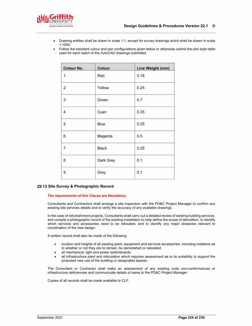
Design Guidelines & Procedures Version 22.1 ©
September 2021 Page 224 of 230
Drawing entities shall be drawn in scale 1:1, except for survey drawings which shall be drawn in scale 1:1000.
Follow the standard colour and pen configurations given below or otherwise submit the plot style table used for each batch of the AutoCAD drawings submitted.
Colour No. Colour Line Weight (mm)
1 Red 0.18
2 Yellow 0.25
3 Green 0.7
4 Cyan 0.35
5 Blue 0.25
6 Magenta 0.5
7 Black 0.25
8 Dark Grey 0.1
9 Grey 0.1
Site Survey & Photographic Record The requirements of this Clause are Mandatory. Consultants and Contractors shall arrange a site inspection with the PD&C Project Manager to confirm any existing site services details and to verify the accuracy of any available drawings. In the case of refurbishment projects, Consultants shall carry out a detailed review of existing building services, and compile a photographic record of the existing installation to help define the scope of demolition, to identify which services and accessories need to be relocated, and to identify any major obstacles relevant to coordination of the new design. A written record shall also be made of the following;
location and heights of all existing plant, equipment and services accessories, including notations as to whether or not they are to remain, be demolished or relocated.
all mechanical, light and power switchboards. all infrastructure plant and reticulation which requires assessment as to its suitability to support the
proposed new use of the building or designated spaces. The Consultant or Contractor shall make an assessment of any existing code non-conformances or infrastructure deficiencies and communicate details of same to the PD&C Project Manager. Copies of all records shall be made available to CLF.
Design Guidelines & Procedures Version 22.1 ©
September 2021 Page 225 of 230
Communication with GU Project Personnel It is the responsibility of all Consultants to maintain regular communication with their GU technical service discipline counterpart, to ensure that each is fully briefed on the progress and direction of the design philosophy. It is in the interests of both the Consultant and GU that all stakeholders are kept fully informed and involved in the design process, through the PD&C Project Manager.
Document Review and Compliance with the GU Design Guidelines The requirements of this Clause are Mandatory. In addition to the Consultant’s or Contractor’s normal ‘in house’ design and quality control reviews carried out prior to documents being issued to CLF for review and comment, a dedicated Design Guidelines audit must be carried out before the documents are formally issued. No documents are to be issued for tender purposes before a Design Guidelines audit has been undertaken. The Consultant or Contractor must also ensure that interim preliminary issues are made to the PD&C Project Manager for distribution to key Users. The transmittal must clearly identify to whom the documents have been issued and for what purpose.
Building Services Plans of Altered Existing Buildings The requirements of this Clause are Mandatory. Where a Consultant undertakes design services for a major alterations/refurbishment project (over $250,000 in value), the Consultant will be required to add to his drawings all existing building services of the Building level or levels to be altered/refurbished, in CAD format, where the existing services have not previously been documented in that format. If the existing building services to the altered/refurbished Building level or levels have been documented in CAD format and are in the possession of CLF, copies of the relevant files will be provided to assist the Consultant. The building services files are to be:
Communications, Electrical and Fire Hydraulics Mechanical
The relevant electronic files of architectural floor plan of the Building level or levels will be supplied in AutoCAD format for reference upon request. The PD&C Project Manager is to be notified of any discrepancies found in the floor plan.
Practical Completion Practical Completion will be determined only by the Associate Director, Minor Projects (PD&C) CLF, on the advice of the PD&C Project Manager and Consultants. The Certificate of Practical Completion will be issued by the Superintendent. The Certificate will not be issued until such time as all systems have been properly commissioned and are fully operational, inspections have been completed and passed by QFES, and a ‘Certificate of Classification Occupancy’ has been issued by the University's appointed Building Surveyor. Prior to issue of the Certificate, GU personnel will carry out comprehensive inspections of the works. These inspections will not commence until such time as all Consultants have completed their inspections and necessary rectification has been carried out. Not less than two (2) weeks should be allowed for the GU inspections and tests. The outcome of these inspections will in no way absolve the Consultant or Contractor from any subsequent problems or defects that may become apparent as part of the new works.
Design Guidelines & Procedures Version 22.1 ©
September 2021 Page 226 of 230
Work Opportunities for GU Students Contractors undertaking construction works for GU, and Design Consultants awarded commissions to design and document GU projects either by direct appointment by GU or appointed by a Contractor, are encouraged to provide work experience and training opportunities for students enrolled in appropriate courses at GU. In particular, students enrolled with the Schools of Engineering, Environment (Architecture) and Information & Communications Technology, would benefit from receiving some practical experience and training from Engineering and Architectural Consultants, on the University’s own projects, to comply with the Engineers Australia and Australian Institute of Architects requirements and policies for industry experience. Courses with particular application to GU capital projects are as follows;
Civil, structural & geotechnical engineering Architecture Mechanical engineering Electrical & electronic engineering Mechatronic engineering Environmental engineering Environmental science Information technology & computing Urban & environmental planning
Contractors and Consultants can seek further information regarding the relevant School’s objectives for industry training including the Industry Affiliates Program on the GU website www.griffith.edu.au.
Design Guidelines & Procedures Version 22.1 ©
September 2021 Page 227 of 230
30.00 Certification under the Building Act at Griffith University
Background By Order-In-Council made on the 13th January 1983, as amended by Order-In-Council 13th November 1986, GU is deemed to represent the Crown in right of the State for the purposes of the Building Act. In 1999 all GU campuses were designated as Community Infrastructure under Part 6 of the Integrated Planning Act. The result of this Order-In-Council and Ministerial Designation is that all building work carried out within the University is assessed for Building Act compliance by the University. To meet its obligations, the University will appoint a Registered Building Surveyor for each project to perform the building surveying duties.
Obtaining Building Approval Building approvals are to be obtained from the GU appointed Building Surveyor (UBS) for all building works which involve alterations to existing walls, extensions to existing buildings and the construction of new buildings. A building application submitted to the UBS shall include three (3) copies of all documents listed below: Note: With regard to plans, two (2) A3 copies and one (1) A1 copy of all drawings requested is to be provided. The A1 set is required for lodgement with Queensland Fire & Rescue Service (QFES). Building Application and Certificates Building Application Forms Part A & B available at - https://www.business.qld.gov.au/industries/building-property-development/building-construction/forms-guidelines Architectural Floor Plans, Elevations and Sections Architects Design Certificates Structural Design Drawings Structural Design Certificate Mechanical Design Drawings Mechanical Design Certificate Electrical Floor Plans (indicating Exit Signs and Emergency Light) Electrical Design Certificate Hydraulic Floor Plans (indicating Booster Hydrant and Hose reels locations including fire hydrant hose and hose reel travel paths) Hydraulic Design Certificate Fire Services Floor Plans (indicating All Special Fire Services) Fire Detection & Warning System Design Certificate Note: Standard Certificates (Form 15) available at -http://www.hpw.qld.gov.au/aboutus/ReportsPublications/FormsTemplates/Pages/BuildingForms.aspx
Process for Obtaining Building Approval Obtaining Building Approval The Coordinating Consultant or Contractor is to coordinate and lodge all documentation described in Section 24.1 to the UBS prior to issuing tender documents or within four (4) weeks of agreeing Total Project Sum (TPS) for Design & Construct projects.
Design Guidelines & Procedures Version 22.1 ©
September 2021 Page 228 of 230
When building work is approved, the UBS will return one (1) set of the approved documentation to the Applicant. During Construction The Applicant and all relevant consultants will carry out inspections of the building work to check general compliance with the approved documentation. The UBS will be available to answer questions or carry out specific inspections as the need arises. The Applicant must keep the UBS informed about any amendments which may effect the building’s compliance with the Building Legislation. At Practical Completion The Applicant shall advise the UBS that all work has been completed in accordance with the approved documents and of any changes affecting the Buildings Compliance, which happened during the construction period. Copies of Consultants completion certificates and all other relevant certificates are to be provided to the UBS. The UBS and the Superintendent (SUPERINTENDENT) shall be invited to witness all testing prior to inspection by the QFES. The UBS will issue the Certificate of Classification for the building once completion and compliance is achieved. Note: Standard Completion Certificate (Form 16). must be submitted in order for a Certificate of Classification to be issued if required.
Queensland Fire and Emergency Services Approvals The QFES approval for Special Fire Services is required by the University acting as the Local Authority under the Building Act. Once all relevant documentation is received, the UBS will arrange lodgement of the Special Fire Services application to the QFES and payment of the relevant fees.
Health Approvals The Coordinating Consultant or Contractor is to obtain the Health approvals from the relevant Local Authority. Note: Building approval will not be issued by the UBS until Health comments are received.
Sewerage and Water Supply Approval The Coordinating Consultant or Contractor shall coordinate documents, pay all associated fees and obtain approval from the relevant local authority as required under the Sewerage and Water Supply Act. This application is to be made at the same time as lodging the Building Application with the University.
Design Guidelines & Procedures Version 22.1 ©
September 2021 Page 229 of 230
31.00 Standard Drawings The following drawings have been adopted as standard details by the University. The details shall be used wherever applicable. Drawings are available at GU Standard Drawings. Alterations to details must be approved by the University Project Manager
General Revision
GSD-001A Standard Drawing Title Block Format 5
GSD-001B Drawing Numbering System 4
GSD-001C Standard Discipline Codes 5
GSD-001D Operation & Maintenance Manual Cover -
External Work
GSD-103 Bicycle Rack 5
GSD-105 External Hose Cock 3
GSD-106 Typical Eave Gutter 4
GSD-107 Double “K” Flashing 3
Benches
GSD-201A Typical Laboratory Bench with Services 3
GSD-201B Typical Laboratory Bench with Services 3
GSD-202 Laboratory Sink 3
Room Layouts
GSD-300 Typical 12m2 office 3
GSD-301 Typical 18m2 and 24m2 offices 3
GSD-302 Typical Kitchenette 3
Furniture and Fixtures
GSD-400 Door Hardware Setout 3
GSD-401 Lock and Handle for Aluminium Doors 3
GSD-402 Lockable Staff Mail Box Unit 3
GSD-403 Assignment Return and Mail Box Unit 3
GSD-404 Lockable Notice Board 3
GSD-407 Typical Corner Workstation 4
GSD-409 Typical Indoor Waste & Recycle Station 1
Audio Visual Revision
GSD-501 Data Projector Mounting Plate – Large Theatre
3
GSD-502 Acrylic Instruction Panel for Lecture Theatres 3
GSD-505A Lecture Theatre Audio Visual Cabling Schematic
3
GSD-505B Lecture Theatre Audio Visual Cabling Schematic Cont.
3
GSD-505C
Video Conferencing Lecture Theatre – Additional Audio Visual
3
Design Guidelines & Procedures Version 22.1 ©
September 2021 Page 230 of 230
GSD-506 Wiring Specs for AMX & Data Projection in Seminar Rooms
3
GSD-507 Projector Mounting Pole – Seminar/Computing Rooms
3
GSD-508 Video Conference: Data Projector Wiring Specification for Medium Rooms
3
GSD-509 Video Conference: Plasma Monitor Wiring Specification for Meeting Rooms
3
Air Conditioning
GSD-600 Typical Switchboard Fascia Details 3
GSD-601 Indicative Schematic for Design of Nederman Arm Extraction System
-
Telecommunications
GSD-700 Telecommunications Subsystems 3
GSD-701 Typical Cabinet Configuration 6
GSD-702 Telecommunications Labelling 4
GSD-703 Typical Layout of Telecommunications Equipment Room
4
GSD-704 MDF Frame Mounting Heights & Accessibility -
GSD-705 Cable Identification Tag 1


![[XLS] · Web viewCONSOLIDADO TOTAL ESCOPETA REVOLVER CARABINAS PISTOLA MARCA 0.00 0.00 1.00 1.00 MODELO 0.00 0.00 1.00 1.00 TIPOARMA 0.00 0.00 1.00 1.00 NRO TIPO_ARMA MARCA MODELO](https://img.pdfslide.net/doc/110x75/5b0bc0427f8b9a685a8b515e/xls-viewconsolidado-total-escopeta-revolver-carabinas-pistola-marca-000-000.jpg)