Embed Size (px)
DESCRIPTION
Component housings – WAVEBOX M.4 Housings in terminal form – DK M.21 M Housings in terminal form – MCZ M.24 Component housings – MICROBOX 6 M.10 Installation housings in profile form – RS M.16 Contents Housings for Electronics Housings for Electronics M.1
Citation preview
Ho
usin
gs f
or
Ele
ctr
on
ics
M.1
M
Housings for Electronics
Overview M.2
Component housings – WAVEBOX M.4
Component housings – MICROBOX 6 M.10
Component housings – EG M.11
Installation housings in profile form – RS M.16
Housings in terminal form – DK M.21
Housings in terminal form – MCZ M.24
IP68 housing – JACKPAC® M.25
Housings for Electronics
Contents
Ho
usin
gs f
or
Ele
ctr
on
ics
M.2
M
Overview
Housings for Electronics
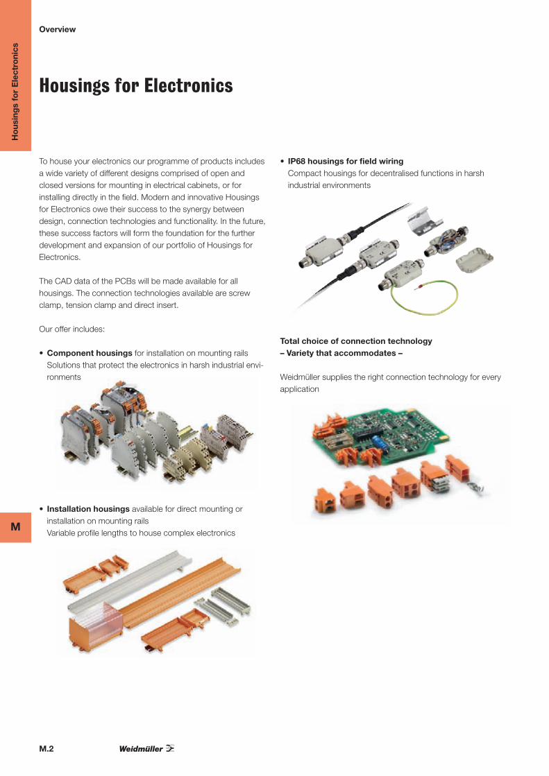
• IP68 housings for field wiring
Compact housings for decentralised functions in harsh
industrial environments
Total choice of connection technology
– Variety that accommodates –
Weidmüller supplies the right connection technology for every
application
To house your electronics our programme of products includes
a wide variety of different designs comprised of open and
closed versions for mounting in electrical cabinets, or for
installing directly in the field. Modern and innovative Housings
for Electronics owe their success to the synergy between
design, connection technologies and functionality. In the future,
these success factors will form the foundation for the further
development and expansion of our portfolio of Housings for
Electronics.
The CAD data of the PCBs will be made available for all
housings. The connection technologies available are screw
clamp, tension clamp and direct insert.
Our offer includes:
• Component housings for installation on mounting rails
Solutions that protect the electronics in harsh industrial envi-
ronments
• Installation housings available for direct mounting or
installation on mounting rails
Variable profile lengths to house complex electronics
Ho
usin
gs f
or
Ele
ctr
on
ics
M.3
M
Overview
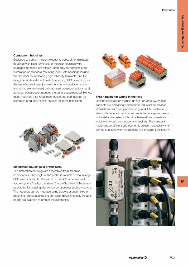
Component housings
Designed to contain modern electronic pcbs, either miniature
housings with fixed terminals, or modular housings with
pluggable terminals are offered. Both provide vibration-proof
installation on standard mounting rails. Both housings include
Weidmüller’s marketleading high reliability terminals, and the
design facilitates efficient heat dissipation, EMC protection, and
the use of operating/adjustment functions. Installation costs
and wiring are minimised by integrated crossconnections, and
compact construction reduces the panel space needed. Hence,
these housings offer reliable protection and connections for
electronic products, as well as cost-effective installation.
Installation housings in profile form
The installation housings are assembled from modular
components. The length of the profile is variable so that a large
PCB area is available. The width of the PCB is determined
according to a fixed grid system. The profile offers high-density
packaging for housing electronics components and connectors.
The housings can be mounted using screws or assembled on
mounting rails by utilising the corresponding fixing feet. Suitable
hoods are available to protect the electronics.
IP68 housing for wiring in the field
Decentralised systems which do not use large switchgear
cabinets are increasingly preferred in industrial automation
installations. With compact housings and IP68 protection,
Weidmüller offers a modular and versatile concept for use in
industrial environments. Electrical terminations is made via
industry standard connectors and sockets. The compact
housing is an efficient and economic solution, especially when it
comes to bus network installations or increasing functionality.
M.4
M
Ho
usin
gs
for
Ele
ctro
nics
Component housings
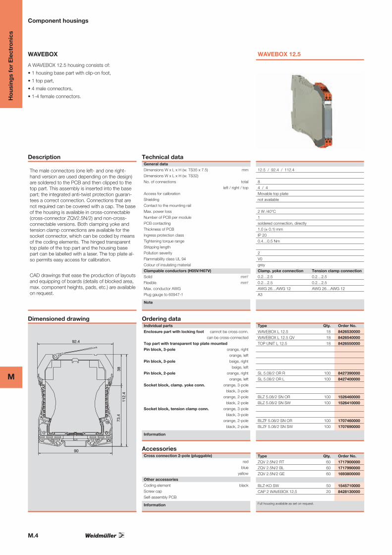
WAVEBOX
A WAVEBOX 12.5 housing consists of:
• 1 housing base part with clip-on foot,
• 1 top part,
• 4 male connectors,
• 1-4 female connectors.
Description
The male connectors (one left- and one right-hand version are used depending on the design)are soldered to the PCB and then clipped to thetop part. This assembly is inserted into the basepart; the integrated anti-twist protection guaran-tees a correct connection. Connections that arenot required can be covered with a cap. The baseof the housing is available in cross-connectable(cross-connector ZQV2.5N/2) and non-cross-connectable versions. Both clamping yoke andtension clamp connections are available for thesocket connector, which can be coded by meansof the coding elements. The hinged transparenttop plate of the top part and the housing basepart can be labelled with a laser. The top plate al-so permits easy access for calibration.
CAD drawings that ease the production of layoutsand equipping of boards (details of blocked area,max. component heights, pads, etc.) are availableon request.
Dimensioned drawing
92.4
3811
2.4
73.4
90
Technical dataGeneral data
Dimensions W x L x H (w. TS35 x 7.5) mm
Dimensions W x L x H (w. TS32)
No. of connections total
left / right / top
Access for calibration
Shielding
Contact to the mounting rail
Max. power loss
Number of PCB per module
PCB contacting
Thickness of PCB
Ingress protection class
Tightening torque range
Stripping length
Pollution severity
Flammability class UL 94
Colour of insulating material
Clampable conductors (H05V/H07V)
Solid mm2
Flexible mm2
Max. conductor AWG
Plug gauge to 60947-1
Note
Ordering dataIndividual parts
Enclosure part with locking foot cannot be cross-conn.
can be cross-connected
Top part with transparent top plate mounted
Pin block, 3-pole orange, right
orange, left
Pin block, 3-pole beige, right
beige, left
Pin block, 2-pole orange, right
orange, left
Socket block, clamp. yoke conn. orange, 3-pole
black, 3-pole
orange, 2-pole
black, 2-pole
Socket block, tension clamp conn. orange, 3-pole
black, 3-pole
orange, 2-pole
black, 2-pole
Information
AccessoriesCross connection 2-pole (pluggable)
red
blue
yellow
Other accessories
Coding element black
Screw cap
Self-assembly PCB
Information
WAVEBOX 12.5
12.5 / 92.4 / 112.4
8
4 / 4
Movable top plate
not available
2 W /40°C
1
soldered connection, directly
1.0 (± 0.1) mm
IP 20
0.4…0.5 Nm
2
V0
grey
Clamp. yoke connection Tension clamp connection
0.2…2.5 0.2…2.5
0.2…2.5 0.2…2.5
AWG 26…AWG 12 AWG 26…AWG 12
A3
Type Qty. Order No.
WAVEBOX L 12.5 18 8426530000
WAVEBOX L 12.5 QV 18 8426540000
TOP UNIT L 12.5 18 8426550000
SL 5.08/2 OR R 100 8427390000
SL 5.08/2 OR L 100 8427400000
BLZ 5.08/2 SN OR 100 1526460000
BLZ 5.08/2 SN SW 100 1526410000
BLZF 5.08/2 SN OR 100 1707460000
BLZF 5.08/2 SN SW 100 1707690000
Type Qty. Order No.
ZQV 2.5N/2 RT 60 1717900000
ZQV 2.5N/2 BL 60 1717990000
ZQV 2.5N/2 GE 60 1693800000
BLZ-KO SW 50 1545710000
CAP 2 WAVEBOX 12,5 20 8428130000
Full housing available as set on request.
M.5
MH
ous
ing
s fo
r E
lect
roni
cs
Component housings
WAVEBOX
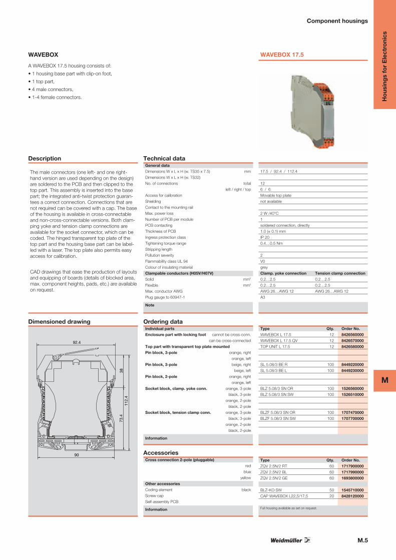
A WAVEBOX 17.5 housing consists of:
• 1 housing base part with clip-on foot,
• 1 top part,
• 4 male connectors,
• 1-4 female connectors.
Description
The male connectors (one left- and one right-hand version are used depending on the design)are soldered to the PCB and then clipped to thetop part. This assembly is inserted into the basepart; the integrated anti-twist protection guaran-tees a correct connection. Connections that arenot required can be covered with a cap. The baseof the housing is available in cross-connectableand non-cross-connectable versions. Both clam-ping yoke and tension clamp connections areavailable for the socket connector, which can becoded. The hinged transparent top plate of thetop part and the housing base part can be label-led with a laser. The top plate also permits easyaccess for calibration.
CAD drawings that ease the production of layoutsand equipping of boards (details of blocked area,max. component heights, pads, etc.) are availableon request.
Dimensioned drawing
92.4
3811
2.4
73.4
90
Technical dataGeneral data
Dimensions W x L x H (w. TS35 x 7.5) mm
Dimensions W x L x H (w. TS32)
No. of connections total
left / right / top
Access for calibration
Shielding
Contact to the mounting rail
Max. power loss
Number of PCB per module
PCB contacting
Thickness of PCB
Ingress protection class
Tightening torque range
Stripping length
Pollution severity
Flammability class UL 94
Colour of insulating material
Clampable conductors (H05V/H07V)
Solid mm2
Flexible mm2
Max. conductor AWG
Plug gauge to 60947-1
Note
Ordering dataIndividual parts
Enclosure part with locking foot cannot be cross-conn.
can be cross-connected
Top part with transparent top plate mounted
Pin block, 3-pole orange, right
orange, left
Pin block, 3-pole beige, right
beige, left
Pin block, 2-pole orange, right
orange, left
Socket block, clamp. yoke conn. orange, 3-pole
black, 3-pole
orange, 2-pole
black, 2-pole
Socket block, tension clamp conn. orange, 3-pole
black, 3-pole
orange, 2-pole
black, 2-pole
Information
AccessoriesCross connection 2-pole (pluggable)
red
blue
yellow
Other accessories
Coding element black
Screw cap
Self-assembly PCB
Information
WAVEBOX 17.5
17.5 / 92.4 / 112.4
12
6 / 6
Movable top plate
not available
2 W /40°C
1
soldered connection, directly
1.0 (± 0.1) mm
IP 20
0.4…0.5 Nm
2
V0
grey
Clamp. yoke connection Tension clamp connection
0.2…2.5 0.2…2.5
0.2…2.5 0.2…2.5
AWG 26…AWG 12 AWG 26…AWG 12
A3
Type Qty. Order No.
WAVEBOX L 17.5 12 8426560000
WAVEBOX L 17.5 QV 12 8426570000
TOP UNIT L 17.5 12 8426580000
SL 5.08/3 BE R 100 8449220000
SL 5.08/3 BE L 100 8449230000
BLZ 5.08/3 SN OR 100 1526560000
BLZ 5.08/3 SN SW 100 1526510000
BLZF 5.08/3 SN OR 100 1707470000
BLZF 5.08/3 SN SW 100 1707700000
Type Qty. Order No.
ZQV 2.5N/2 RT 60 1717900000
ZQV 2.5N/2 BL 60 1717990000
ZQV 2.5N/2 GE 60 1693800000
BLZ-KO SW 50 1545710000
CAP WAVEBOX L22,5/17,5 20 8428120000
Full housing available as set on request.
M.6
M
Ho
usin
gs
for
Ele
ctro
nics
Component housings
WAVEBOX
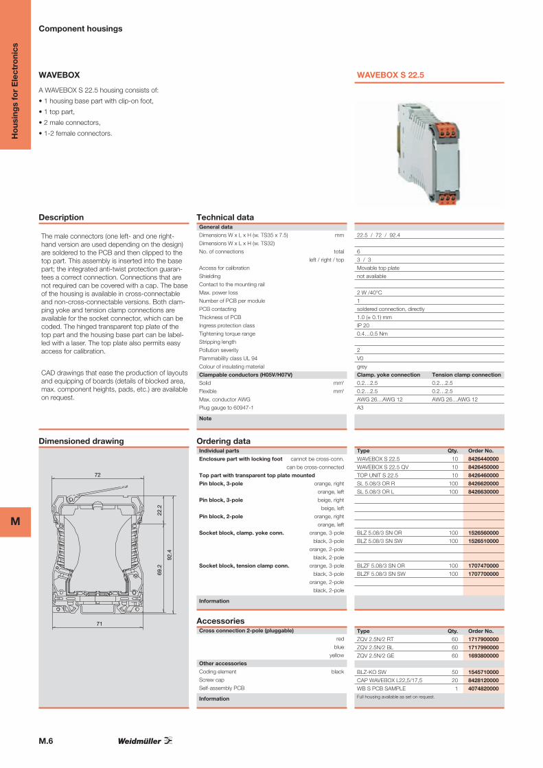
A WAVEBOX S 22.5 housing consists of:
• 1 housing base part with clip-on foot,
• 1 top part,
• 2 male connectors,
• 1-2 female connectors.
Description
The male connectors (one left- and one right-hand version are used depending on the design)are soldered to the PCB and then clipped to thetop part. This assembly is inserted into the basepart; the integrated anti-twist protection guaran-tees a correct connection. Connections that arenot required can be covered with a cap. The baseof the housing is available in cross-connectableand non-cross-connectable versions. Both clam-ping yoke and tension clamp connections areavailable for the socket connector, which can becoded. The hinged transparent top plate of thetop part and the housing base part can be label-led with a laser. The top plate also permits easyaccess for calibration.
CAD drawings that ease the production of layoutsand equipping of boards (details of blocked area,max. component heights, pads, etc.) are availableon request.
Dimensioned drawing
72
22.2
92.4
69.2
71
Technical dataGeneral data
Dimensions W x L x H (w. TS35 x 7.5) mm
Dimensions W x L x H (w. TS32)
No. of connections total
left / right / top
Access for calibration
Shielding
Contact to the mounting rail
Max. power loss
Number of PCB per module
PCB contacting
Thickness of PCB
Ingress protection class
Tightening torque range
Stripping length
Pollution severity
Flammability class UL 94
Colour of insulating material
Clampable conductors (H05V/H07V)
Solid mm2
Flexible mm2
Max. conductor AWG
Plug gauge to 60947-1
Note
Ordering dataIndividual parts
Enclosure part with locking foot cannot be cross-conn.
can be cross-connected
Top part with transparent top plate mounted
Pin block, 3-pole orange, right
orange, left
Pin block, 3-pole beige, right
beige, left
Pin block, 2-pole orange, right
orange, left
Socket block, clamp. yoke conn. orange, 3-pole
black, 3-pole
orange, 2-pole
black, 2-pole
Socket block, tension clamp conn. orange, 3-pole
black, 3-pole
orange, 2-pole
black, 2-pole
Information
AccessoriesCross connection 2-pole (pluggable)
red
blue
yellow
Other accessories
Coding element black
Screw cap
Self-assembly PCB
Information
WAVEBOX S 22.5
22.5 / 72 / 92.4
6
3 / 3
Movable top plate
not available
2 W /40°C
1
soldered connection, directly
1.0 (± 0.1) mm
IP 20
0.4…0.5 Nm
2
V0
grey
Clamp. yoke connection Tension clamp connection
0.2…2.5 0.2…2.5
0.2…2.5 0.2…2.5
AWG 26…AWG 12 AWG 26…AWG 12
A3
Type Qty. Order No.
WAVEBOX S 22.5 10 8426440000
WAVEBOX S 22.5 QV 10 8426450000
TOP UNIT S 22.5 10 8426460000
SL 5.08/3 OR R 100 8426620000
SL 5.08/3 OR L 100 8426630000
BLZ 5.08/3 SN OR 100 1526560000
BLZ 5.08/3 SN SW 100 1526510000
BLZF 5.08/3 SN OR 100 1707470000
BLZF 5.08/3 SN SW 100 1707700000
Type Qty. Order No.
ZQV 2.5N/2 RT 60 1717900000
ZQV 2.5N/2 BL 60 1717990000
ZQV 2.5N/2 GE 60 1693800000
BLZ-KO SW 50 1545710000
CAP WAVEBOX L22,5/17,5 20 8428120000
WB S PCB SAMPLE 1 4074820000Full housing available as set on request.
M.7
MH
ous
ing
s fo
r E
lect
roni
cs
Component housings
WAVEBOX
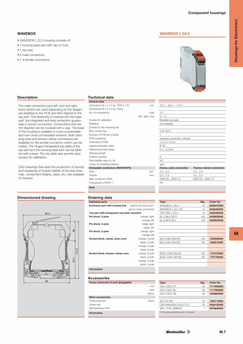
A WAVEBOX L 22.5 housing consists of:
• 1 housing base part with clip-on foot,
• 1 top part,
• 4 male connectors,
• 1-4 female connectors.
Description
The male connectors (one left- and one right-hand version are used depending on the design)are soldered to the PCB and then clipped to thetop part. This assembly is inserted into the basepart; the integrated anti-twist protection guaran-tees a correct connection. Connections that arenot required can be covered with a cap. The baseof the housing is available in cross-connectableand non-cross-connectable versions. Both clam-ping yoke and tension clamp connections areavailable for the socket connector, which can becoded. The hinged transparent top plate of thetop part and the housing base part can be label-led with a laser. The top plate also permits easyaccess for calibration.
CAD drawings that ease the production of layoutsand equipping of boards (details of blocked area,max. component heights, pads, etc.) are availableon request.
Dimensioned drawing
92.4
3811
2.4
73.4
90
Technical dataGeneral data
Dimensions W x L x H (w. TS35 x 7.5) mm
Dimensions W x L x H (w. TS32)
No. of connections total
left / right / top
Access for calibration
Shielding
Contact to the mounting rail
Max. power loss
Number of PCB per module
PCB contacting
Thickness of PCB
Ingress protection class
Tightening torque range
Stripping length
Pollution severity
Flammability class UL 94
Colour of insulating material
Clampable conductors (H05V/H07V)
Solid mm2
Flexible mm2
Max. conductor AWG
Plug gauge to 60947-1
Note
Ordering dataIndividual parts
Enclosure part with locking foot cannot be cross-conn.
can be cross-connected
Top part with transparent top plate mounted
Pin block, 3-pole orange, right
orange, left
Pin block, 3-pole beige, right
beige, left
Pin block, 2-pole orange, right
orange, left
Socket block, clamp. yoke conn. orange, 3-pole
black, 3-pole
orange, 2-pole
black, 2-pole
Socket block, tension clamp conn. orange, 3-pole
black, 3-pole
orange, 2-pole
black, 2-pole
Information
AccessoriesCross connection 2-pole (pluggable)
red
blue
yellow
Other accessories
Coding element black
Screw cap
Self-assembly PCB
Information
WAVEBOX L 22.5
22.5 / 92.4 / 112.4
12
6 / 6
Movable top plate
not available
2 W /40°C
1
soldered connection, directly
1.0 (± 0.1) mm
IP 20
0.4…0.5 Nm
2
V0
grey
Clamp. yoke connection Tension clamp connection
0.2…2.5 0.2…2.5
0.2…2.5 0.2…2.5
AWG 26…AWG 12 AWG 26…AWG 12
A3
Type Qty. Order No.
WAVEBOX L 22.5 10 8426470000
WAVEBOX L 22.5 QV 10 8426480000
TOP UNIT L 22.5 10 8426490000
SL 5.08/3 OR R 100 8426620000
SL 5.08/3 OR L 100 8426630000
BLZ 5.08/3 SN OR 100 1526560000
BLZ 5.08/3 SN SW 100 1526510000
BLZF 5.08/3 SN OR 100 1707470000
BLZF 5.08/3 SN SW 100 1707700000
Type Qty. Order No.
ZQV 2.5N/2 RT 60 1717900000
ZQV 2.5N/2 BL 60 1717990000
ZQV 2.5N/2 GE 60 1693800000
BLZ-KO SW 50 1545710000
CAP WAVEBOX L22,5/17,5 20 8428120000
WB L PCB SAMPLE 1 4074640000Full housing available as set on request.
M.8
M
Ho
usin
gs
for
Ele
ctro
nics
Component housings
WAVEBOX
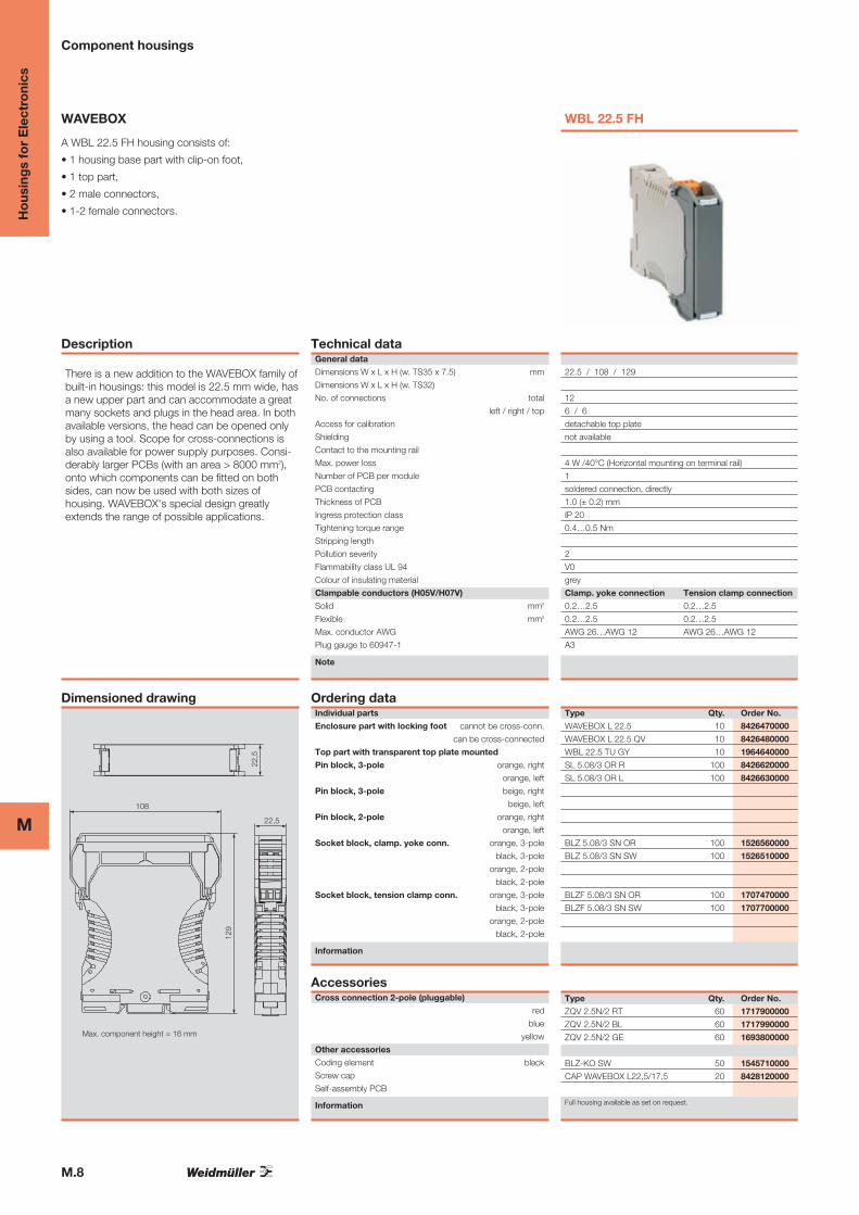
A WBL 22.5 FH housing consists of:
• 1 housing base part with clip-on foot,
• 1 top part,
• 2 male connectors,
• 1-2 female connectors.
Description
There is a new addition to the WAVEBOX family ofbuilt-in housings: this model is 22.5 mm wide, hasa new upper part and can accommodate a greatmany sockets and plugs in the head area. In bothavailable versions, the head can be opened onlyby using a tool. Scope for cross-connections isalso available for power supply purposes. Consi-derably larger PCBs (with an area > 8000 mm2),onto which components can be fitted on bothsides, can now be used with both sizes ofhousing. WAVEBOX's special design greatlyextends the range of possible applications.
Dimensioned drawing
22,5
129
22,5
108
Max. component height = 16 mm
Technical dataGeneral data
Dimensions W x L x H (w. TS35 x 7.5) mm
Dimensions W x L x H (w. TS32)
No. of connections total
left / right / top
Access for calibration
Shielding
Contact to the mounting rail
Max. power loss
Number of PCB per module
PCB contacting
Thickness of PCB
Ingress protection class
Tightening torque range
Stripping length
Pollution severity
Flammability class UL 94
Colour of insulating material
Clampable conductors (H05V/H07V)
Solid mm2
Flexible mm2
Max. conductor AWG
Plug gauge to 60947-1
Note
Ordering dataIndividual parts
Enclosure part with locking foot cannot be cross-conn.
can be cross-connected
Top part with transparent top plate mounted
Pin block, 3-pole orange, right
orange, left
Pin block, 3-pole beige, right
beige, left
Pin block, 2-pole orange, right
orange, left
Socket block, clamp. yoke conn. orange, 3-pole
black, 3-pole
orange, 2-pole
black, 2-pole
Socket block, tension clamp conn. orange, 3-pole
black, 3-pole
orange, 2-pole
black, 2-pole
Information
AccessoriesCross connection 2-pole (pluggable)
red
blue
yellow
Other accessories
Coding element black
Screw cap
Self-assembly PCB
Information
WBL 22.5 FH
22.5 / 108 / 129
12
6 / 6
detachable top plate
not available
4 W /40°C (Horizontal mounting on terminal rail)
1
soldered connection, directly
1.0 (± 0.2) mm
IP 20
0.4…0.5 Nm
2
V0
grey
Clamp. yoke connection Tension clamp connection
0.2…2.5 0.2…2.5
0.2…2.5 0.2…2.5
AWG 26…AWG 12 AWG 26…AWG 12
A3
Type Qty. Order No.
WAVEBOX L 22.5 10 8426470000
WAVEBOX L 22.5 QV 10 8426480000
WBL 22.5 TU GY 10 1964640000
SL 5.08/3 OR R 100 8426620000
SL 5.08/3 OR L 100 8426630000
BLZ 5.08/3 SN OR 100 1526560000
BLZ 5.08/3 SN SW 100 1526510000
BLZF 5.08/3 SN OR 100 1707470000
BLZF 5.08/3 SN SW 100 1707700000
Type Qty. Order No.
ZQV 2.5N/2 RT 60 1717900000
ZQV 2.5N/2 BL 60 1717990000
ZQV 2.5N/2 GE 60 1693800000
BLZ-KO SW 50 1545710000
CAP WAVEBOX L22,5/17,5 20 8428120000
Full housing available as set on request.
M.9
MH
ous
ing
s fo
r E
lect
roni
cs
Component housings
WAVEBOX
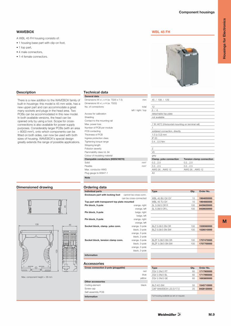
A WBL 45 FH housing consists of:
• 1 housing base part with clip-on foot,
• 1 top part,
• 4 male connectors,
• 1-4 female connectors.
Description
There is a new addition to the WAVEBOX family ofbuilt-in housings: this model is 45 mm wide, has anew upper part and can accommodate a greatmany sockets and plugs in the head area. TwoPCBs can be accommodated in this new model.In both available versions, the head can beopened only by using a tool. Scope for cross-connections is also available for power supplypurposes. Considerably larger PCBs (with an area> 8000 mm2), onto which components can befitted on both sides, can now be used with bothsizes of housing. WAVEBOX's special designgreatly extends the range of possible applications.
Dimensioned drawing
45
129
45108
Max. component height = 38 mm
Technical dataGeneral data
Dimensions W x L x H (w. TS35 x 7.5) mm
Dimensions W x L x H (w. TS32)
No. of connections total
left / right / top
Access for calibration
Shielding
Contact to the mounting rail
Max. power loss
Number of PCB per module
PCB contacting
Thickness of PCB
Ingress protection class
Tightening torque range
Stripping length
Pollution severity
Flammability class UL 94
Colour of insulating material
Clampable conductors (H05V/H07V)
Solid mm2
Flexible mm2
Max. conductor AWG
Plug gauge to 60947-1
Note
Ordering dataIndividual parts
Enclosure part with locking foot cannot be cross-conn.
can be cross-connected
Top part with transparent top plate mounted
Pin block, 3-pole orange, right
orange, left
Pin block, 3-pole beige, right
beige, left
Pin block, 2-pole orange, right
orange, left
Socket block, clamp. yoke conn. orange, 3-pole
black, 3-pole
orange, 2-pole
black, 2-pole
Socket block, tension clamp conn. orange, 3-pole
black, 3-pole
orange, 2-pole
black, 2-pole
Information
AccessoriesCross connection 2-pole (pluggable)
red
blue
yellow
Other accessories
Coding element black
Screw cap
Self-assembly PCB
Information
WBL 45 FH
45 / 108 / 129
12
6 / 6
detachable top plate
not available
7 W /40°C (Horizontal mounting on terminal rail)
1
soldered connection, directly
1.0 (± 0.2) mm
IP 20
0.4…0.5 Nm
2
V0
grey
Clamp. yoke connection Tension clamp connection
0.2…2.5 0.2…2.5
0.2…2.5 0.2…2.5
AWG 26…AWG 12 AWG 26…AWG 12
A3
Type Qty. Order No.
WBL 45 BU QV GY 10 1964650000
WBL 45 TU GY 10 1964660000
SL 5.08/3 OR R 100 8426620000
SL 5.08/3 OR L 100 8426630000
BLZ 5.08/3 SN OR 100 1526560000
BLZ 5.08/3 SN SW 100 1526510000
BLZF 5.08/3 SN OR 100 1707470000
BLZF 5.08/3 SN SW 100 1707700000
Type Qty. Order No.
ZQV 2.5N/2 RT 60 1717900000
ZQV 2.5N/2 BL 60 1717990000
ZQV 2.5N/2 GE 60 1693800000
BLZ-KO SW 50 1545710000
CAP WAVEBOX L22,5/17,5 20 8428120000
Full housing available as set on request.
M.10
M
Ho
usin
gs
for
Ele
ctro
nics
Component housings
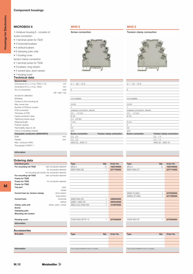
MICROBOX 6
1 miniature housing 6 - consists of:
screw connection
• 1 terminal carrier for TS35
• 2 horizontal busbars
• 4 vertical busbars
• 6 clamping yoke units
• 1 housing cover
tension clamp connection
• 1 terminal carrier for TS35
• 2 busbars, long version
• 4 current bars, short version
• 1 housing coverTechnical dataGeneral data
Dimensions W x L x H (w. TS35 x 7.5) mm
Dimensions W x L x H (w. TS32) mm
No. of connections total
left / right / top
Access for calibration
Shielding
Contact to the mounting rail
Max. power loss
Number of PCB per module
PCB-connection
Thickness of PCB
Ingress protection class
Tightening torque range
Stripping length
Pollution severity
Flammability class UL 94
Colour of insulating material
Clampable conductors (H05V/H07V)
Solid mm2
Flexible mm2
Max. conductor AWG
Plug gauge to 60947-1
Information
Ordering dataIndividual parts
For mounting rail TS35 with connection element
for connection element
for mounting rail contact, for connection element
For mounting rail TS32 with connection element
Frame for TS35
Frame for TS35 for connection element
Frame for TS32
Top part open
closed
Current bars (w. tension clamp) short version
long version
Current bars horizontal
vertical
Clamp. yoke unit clamp. yoke + screw
Screw
Clamping yoke
Mounting rail contact
Housing cover
Information
AccessoriesEnd plate
Information
MHS 6
6.1 / 88 / 97.8
6
not available
0.8 W
1
soldered connection, directly
0.5 … 1.0 mm
IP 20
0.4…0.6 Nm
7 mm
2
V0
grey
Screw connection Tension clamp connection
0.2…2.5
0.2…2.5
AWG 28…AWG 14
Screw connection
Type Qty. Order No.
MHS 6 10 1925740000
EBGH MSA ZB 1 2277700000
SMSE MSA ZB 1 4286620000
SMSE 1 MSD ZB 1 4060540000
ZBSC DLI2.5/M2.5X6 1 1919670000
GHDE MSA ZB FR 12 1 2279280000
Type Qty. Order No.
Full housing available as set on request.
MHZ 6
6.1 / 92 / 97.8
6
not available
0.8 W
1
soldered connection, directly
0.5 … 1.0 mm
IP 20
6 mm
2
V0
grey
Screw connection Tension clamp connection
0.2…1.5
0.2…1.5
AWG 26…AWG 16
Tension clamp connection
Type Qty. Order No.
MHZ 6 10 1925760000
EBGH MSA ZF 1 2277710000
SMSE FE MSA 1 2279350000
SMSE2 ZF MSD 1 2277000000
GHDE MSA ZF 1 2279300000
Type Qty. Order No.
Full housing available as set on request.
M.11
MH
ous
ing
s fo
r E
lect
roni
cs
Component housings
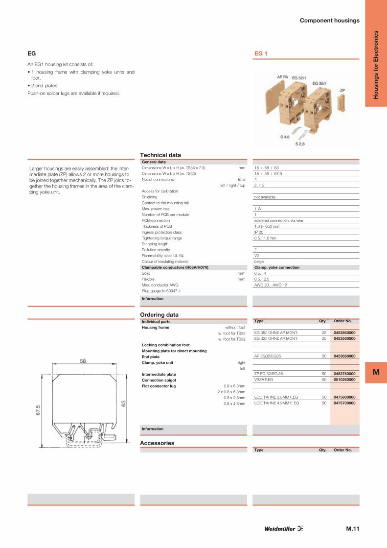
EG
An EG1 housing kit consists of:
• 1 housing frame with clamping yoke units andfoot,
• 2 end plates.
Push-on solder lugs are available if required.
Larger housings are easily assembled: the inter-mediate plate (ZP) allows 2 or more housings tobe joined together mechanically. The ZP joins to-gether the housing frames in the area of the clam-ping yoke unit.
Technical dataGeneral data
Dimensions W x L x H (w. TS35 x 7.5) mm
Dimensions W x L x H (w. TS32)
No. of connections total
left / right / top
Access for calibration
Shielding
Contact to the mounting rail
Max. power loss
Number of PCB per module
PCB-connection
Thickness of PCB
Ingress protection class
Tightening torque range
Stripping length
Pollution severity
Flammability class UL 94
Colour of insulating material
Clampable conductors (H05V/H07V)
Solid mm2
Flexible mm2
Max. conductor AWG
Plug gauge to 60947-1
Information
Ordering dataIndividual parts
Housing frame without foot
w. foot for TS35
w. foot for TS32
Locking combination foot
Mounting plate for direct mounting
End plate
Clamp. yoke unit right
left
Intermediate plate
Connection spigot
Flat connector lug 0.8 x 6.3mm
2 x 0.8 x 6.3mm
0.8 x 2.8mm
0.8 x 4.8mm
Information
Accessories
EG 1
18 / 58 / 63
18 / 58 / 67.5
4
2 / 2
not available
1 W
1
soldered connection, via wire
1.0 (+ 0.2) mm
IP 20
0.5…1.0 Nm
2
V2
beige
Clamp. yoke connection
0.5…4
0.5…2.5
AWG 20…AWG 12
Type Qty. Order No.
EG 35/I OHNE AP MONT. 25 0453860000
EG 32/I OHNE AP MONT. 25 0453560000
AP EG32/EG35 20 0453660000
ZP EG 32/EG 35 50 0453760000
VBZA F.EG 50 0510260000
LOETFAHNE 2.8MM F.EG 50 0475800000
LOETFAHNE 4.9MM F. EG 50 0475700000
Type Qty. Order No.
M.12
M
Ho
usin
gs
for
Ele
ctro
nics
Component housings
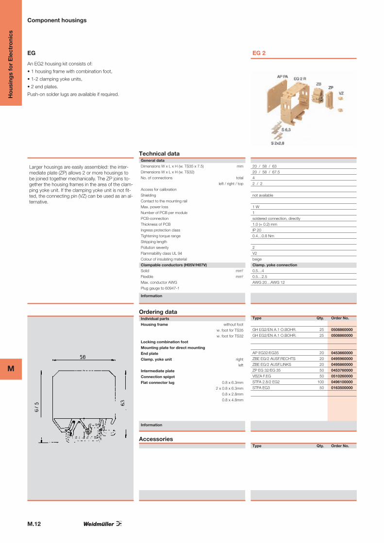
EG
An EG2 housing kit consists of:
• 1 housing frame with combination foot,
• 1-2 clamping yoke units,
• 2 end plates.
Push-on solder lugs are available if required.
Larger housings are easily assembled: the inter-mediate plate (ZP) allows 2 or more housings tobe joined together mechanically. The ZP joins to-gether the housing frames in the area of the clam-ping yoke unit. If the clamping yoke unit is not fit-ted, the connecting pin (VZ) can be used as an al-ternative.
Technical dataGeneral data
Dimensions W x L x H (w. TS35 x 7.5) mm
Dimensions W x L x H (w. TS32)
No. of connections total
left / right / top
Access for calibration
Shielding
Contact to the mounting rail
Max. power loss
Number of PCB per module
PCB-connection
Thickness of PCB
Ingress protection class
Tightening torque range
Stripping length
Pollution severity
Flammability class UL 94
Colour of insulating material
Clampable conductors (H05V/H07V)
Solid mm2
Flexible mm2
Max. conductor AWG
Plug gauge to 60947-1
Information
Ordering dataIndividual parts
Housing frame without foot
w. foot for TS35
w. foot for TS32
Locking combination foot
Mounting plate for direct mounting
End plate
Clamp. yoke unit right
left
Intermediate plate
Connection spigot
Flat connector lug 0.8 x 6.3mm
2 x 0.8 x 6.3mm
0.8 x 2.8mm
0.8 x 4.8mm
Information
Accessories
EG 2
20 / 58 / 63
20 / 58 / 67.5
4
2 / 2
not available
1 W
1
soldered connection, directly
1.0 (+ 0.2) mm
IP 20
0.4…0.8 Nm
2
V2
beige
Clamp. yoke connection
0.5…4
0.5…2.5
AWG 20…AWG 12
Type Qty. Order No.
GH EG2/EN A.1 O.BOHR. 25 0508860000
GH EG2/EN A.1 O.BOHR. 25 0508860000
AP EG32/EG35 20 0453660000
ZBE EG/2 AUSF.RECHTS 20 0495960000
ZBE EG/2 AUSF.LINKS 20 0495860000
ZP EG 32/EG 35 50 0453760000
VBZA F.EG 50 0510260000
STFA 2.8/2 EG2 100 0496100000
STFA EG3 50 0163500000
Type Qty. Order No.
M.13
MH
ous
ing
s fo
r E
lect
roni
cs
Component housings
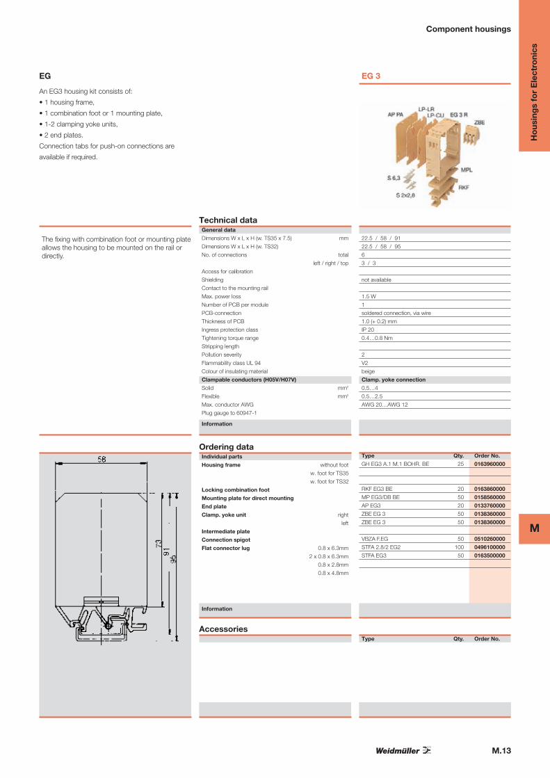
EG
An EG3 housing kit consists of:
• 1 housing frame,
• 1 combination foot or 1 mounting plate,
• 1-2 clamping yoke units,
• 2 end plates.
Connection tabs for push-on connections are
available if required.
The fixing with combination foot or mounting plateallows the housing to be mounted on the rail ordirectly.
Technical dataGeneral data
Dimensions W x L x H (w. TS35 x 7.5) mm
Dimensions W x L x H (w. TS32)
No. of connections total
left / right / top
Access for calibration
Shielding
Contact to the mounting rail
Max. power loss
Number of PCB per module
PCB-connection
Thickness of PCB
Ingress protection class
Tightening torque range
Stripping length
Pollution severity
Flammability class UL 94
Colour of insulating material
Clampable conductors (H05V/H07V)
Solid mm2
Flexible mm2
Max. conductor AWG
Plug gauge to 60947-1
Information
Ordering dataIndividual parts
Housing frame without foot
w. foot for TS35
w. foot for TS32
Locking combination foot
Mounting plate for direct mounting
End plate
Clamp. yoke unit right
left
Intermediate plate
Connection spigot
Flat connector lug 0.8 x 6.3mm
2 x 0.8 x 6.3mm
0.8 x 2.8mm
0.8 x 4.8mm
Information
Accessories
EG 3
22.5 / 58 / 91
22.5 / 58 / 95
6
3 / 3
not available
1.5 W
1
soldered connection, via wire
1.0 (+ 0.2) mm
IP 20
0.4…0.8 Nm
2
V2
beige
Clamp. yoke connection
0.5…4
0.5…2.5
AWG 20…AWG 12
Type Qty. Order No.
GH EG3 A.1 M.1 BOHR. BE 25 0163960000
RKF EG3 BE 20 0163860000
MP EG3/DB BE 50 0158560000
AP EG3 20 0133760000
ZBE EG 3 50 0138360000
ZBE EG 3 50 0138360000
VBZA F.EG 50 0510260000
STFA 2.8/2 EG2 100 0496100000
STFA EG3 50 0163500000
Type Qty. Order No.
M.14
M
Ho
usin
gs
for
Ele
ctro
nics
Component housings
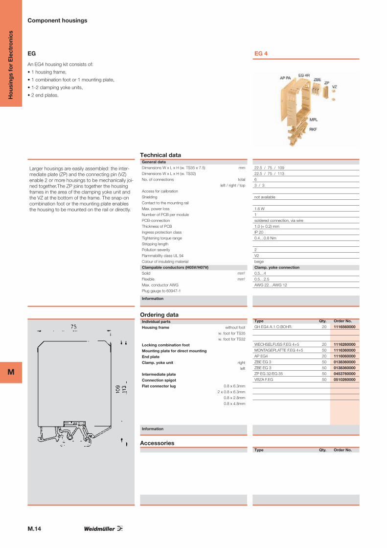
EG
An EG4 housing kit consists of:
• 1 housing frame,
• 1 combination foot or 1 mounting plate,
• 1-2 clamping yoke units,
• 2 end plates.
Larger housings are easily assembled: the inter-mediate plate (ZP) and the connecting pin (VZ)enable 2 or more housings to be mechanically joi-ned together.The ZP joins together the housingframes in the area of the clamping yoke unit andthe VZ at the bottom of the frame. The snap-oncombination foot or the mounting plate enablesthe housing to be mounted on the rail or directly.
Technical dataGeneral data
Dimensions W x L x H (w. TS35 x 7.5) mm
Dimensions W x L x H (w. TS32)
No. of connections total
left / right / top
Access for calibration
Shielding
Contact to the mounting rail
Max. power loss
Number of PCB per module
PCB-connection
Thickness of PCB
Ingress protection class
Tightening torque range
Stripping length
Pollution severity
Flammability class UL 94
Colour of insulating material
Clampable conductors (H05V/H07V)
Solid mm2
Flexible mm2
Max. conductor AWG
Plug gauge to 60947-1
Information
Ordering dataIndividual parts
Housing frame without foot
w. foot for TS35
w. foot for TS32
Locking combination foot
Mounting plate for direct mounting
End plate
Clamp. yoke unit right
left
Intermediate plate
Connection spigot
Flat connector lug 0.8 x 6.3mm
2 x 0.8 x 6.3mm
0.8 x 2.8mm
0.8 x 4.8mm
Information
Accessories
EG 4
22.5 / 75 / 109
22.5 / 75 / 113
6
3 / 3
not available
1.6 W
1
soldered connection, via wire
1.0 (+ 0.2) mm
IP 20
0.4…0.8 Nm
2
V2
beige
Clamp. yoke connection
0.5…4
0.5…2.5
AWG 22…AWG 12
Type Qty. Order No.
GH EG4 A.1 O.BOHR. 20 1116560000
WECHSELFUSS F.EG 4+5 20 1116260000
MONTAGEPLATTE F.EG 4+5 50 1116360000
AP EG4 20 1116060000
ZBE EG 3 50 0138360000
ZBE EG 3 50 0138360000
ZP EG 32/EG 35 50 0453760000
VBZA F.EG 50 0510260000
Type Qty. Order No.
M.15
MH
ous
ing
s fo
r E
lect
roni
cs
Component housings
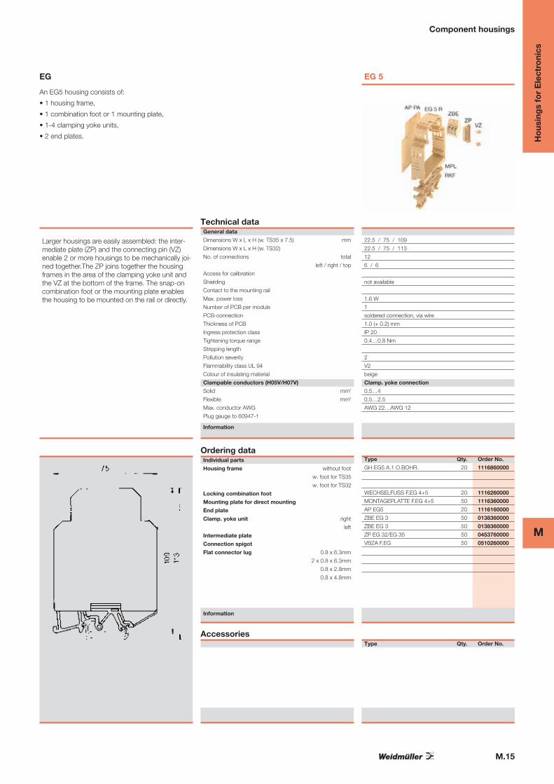
EG
An EG5 housing consists of:
• 1 housing frame,
• 1 combination foot or 1 mounting plate,
• 1-4 clamping yoke units,
• 2 end plates.
Larger housings are easily assembled: the inter-mediate plate (ZP) and the connecting pin (VZ)enable 2 or more housings to be mechanically joi-ned together.The ZP joins together the housingframes in the area of the clamping yoke unit andthe VZ at the bottom of the frame. The snap-oncombination foot or the mounting plate enablesthe housing to be mounted on the rail or directly.
Technical dataGeneral data
Dimensions W x L x H (w. TS35 x 7.5) mm
Dimensions W x L x H (w. TS32)
No. of connections total
left / right / top
Access for calibration
Shielding
Contact to the mounting rail
Max. power loss
Number of PCB per module
PCB-connection
Thickness of PCB
Ingress protection class
Tightening torque range
Stripping length
Pollution severity
Flammability class UL 94
Colour of insulating material
Clampable conductors (H05V/H07V)
Solid mm2
Flexible mm2
Max. conductor AWG
Plug gauge to 60947-1
Information
Ordering dataIndividual parts
Housing frame without foot
w. foot for TS35
w. foot for TS32
Locking combination foot
Mounting plate for direct mounting
End plate
Clamp. yoke unit right
left
Intermediate plate
Connection spigot
Flat connector lug 0.8 x 6.3mm
2 x 0.8 x 6.3mm
0.8 x 2.8mm
0.8 x 4.8mm
Information
Accessories
EG 5
22.5 / 75 / 109
22.5 / 75 / 113
12
6 / 6
not available
1.6 W
1
soldered connection, via wire
1.0 (+ 0.2) mm
IP 20
0.4…0.8 Nm
2
V2
beige
Clamp. yoke connection
0.5…4
0.5…2.5
AWG 22…AWG 12
Type Qty. Order No.
GH EG5 A.1 O.BOHR. 20 1116860000
WECHSELFUSS F.EG 4+5 20 1116260000
MONTAGEPLATTE F.EG 4+5 50 1116360000
AP EG5 20 1116160000
ZBE EG 3 50 0138360000
ZBE EG 3 50 0138360000
ZP EG 32/EG 35 50 0453760000
VBZA F.EG 50 0510260000
Type Qty. Order No.
M.16
M
Ho
usin
gs
for
Ele
ctro
nics
Installation housings in profile form
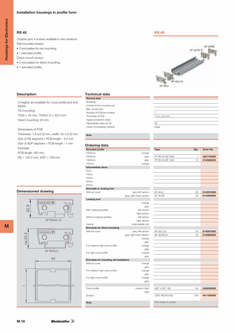
RS 45
Chassis plus 4 screws available in two versions:
Rail-mounted version
• 2 end plates for rail mounting,
• 1 extruded profile,
Direct-mount version
• 2 end plates for direct mounting,
• 1 extruded profile,
Description
3 heights are available for cover profile and endplates:
TS-mounting:
TS32 = 45 mm, TS35x7.5 = 40.5 mm
Direct mounting: 24 mm
Dimensions of PCB
Thickness: 1.6 (±0.2) mm, width: 42 (+0.5) mm
Size of RS segment = PCB length - 4.5 mm
Size of ADP segment = PCB length - 1 mm
Example:
PCB length 160 mm,
RS = 155.5 mm, ADP = 159 mm
Dimensioned drawing
45
lca
.24.
522
.9
AP RS45/LI
AP RS45/L DI
Technical dataGeneral data
Shielding
Contact to the mounting rail
Max. power loss
Number of PCB per module
Thickness of PCB
Ingress protection class
Flammability class UL 94
Colour of insulating material
Note
Ordering dataExtruded profile
2000mm orange
2000mm grey
1000mm grey
155mm orange
Intermediate piece
5mm
15mm
25mm
30mm
45mm
End plate w. locking foot
Without cover grey, left version
grey, right-hand version
Locking foot
orange
grey
With marking facilities left version
right version
Without marking facilities left version
right version
Central intermediate foot
End plate for direct mounting
Without cover grey, left version
grey, right-hand version
orange
grey
For medium-high cover profile orange
grey
For high cover profile orange
grey
End plate for mounting rail installation
Without cover orange
grey
For medium-high cover profile orange
grey
For high cover profile orange
grey
Cover profile medium-high
high
Screws
Note
RS 45
1
1.6 (± 0.2) mm
V2
beige
Type Qty. Order No.
PF RS 45 GR 2000 1 4027750000
PF RS 45 GR 1000 10 8140880000
AP 45/LI 20 8143910000
AP 45/RE 20 8143900000
AP 45/LI DI 20 8140870000
AP 45/RE DI 20 8140860000
ADP 1/HP1 1M 64 0485200000
LKSC M2,9x13VZ 100 4011200000
Other lengths on request.
M.17
MH
ous
ing
s fo
r E
lect
roni
cs
Installation housings in profile form
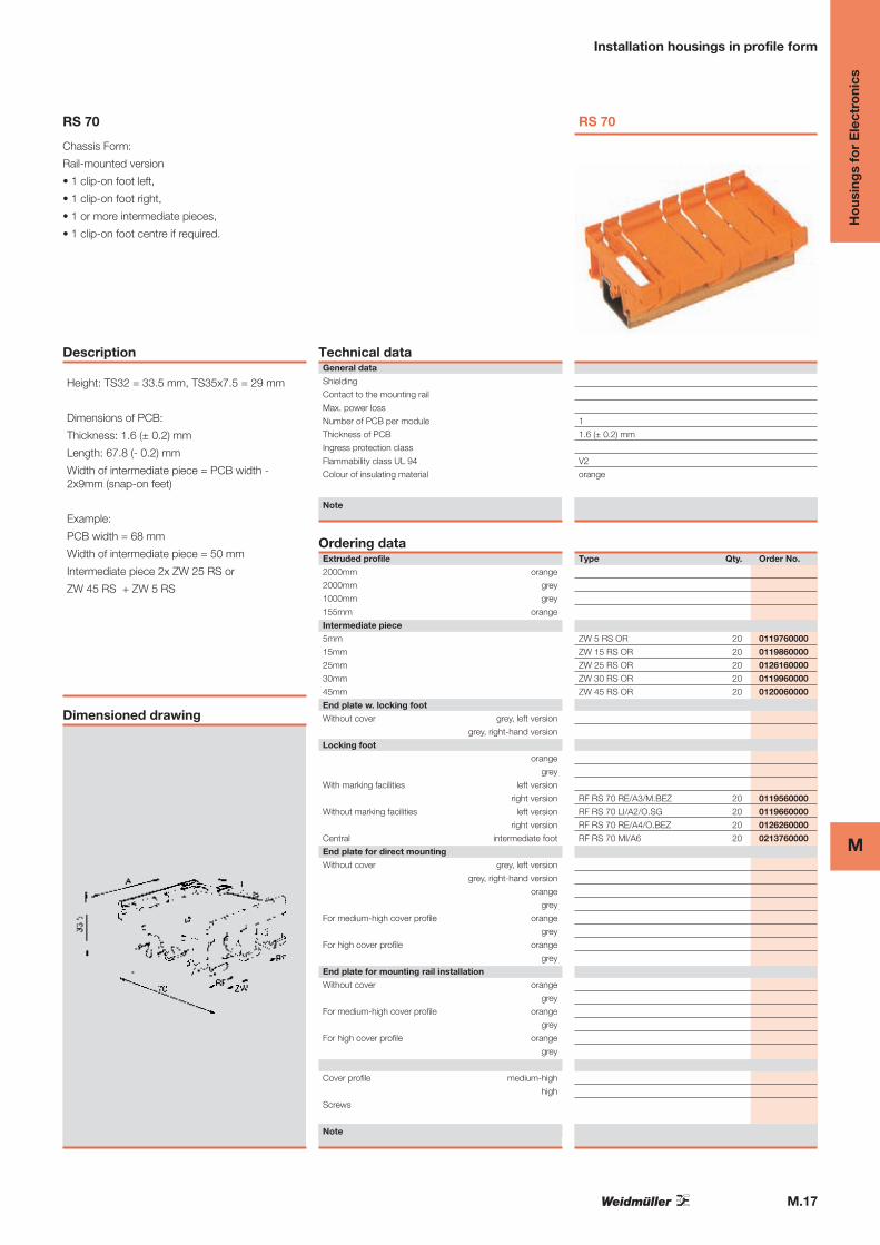
RS 70
Chassis Form:
Rail-mounted version
• 1 clip-on foot left,
• 1 clip-on foot right,
• 1 or more intermediate pieces,
• 1 clip-on foot centre if required.
Description
Height: TS32 = 33.5 mm, TS35x7.5 = 29 mm
Dimensions of PCB:
Thickness: 1.6 (± 0.2) mm
Length: 67.8 (- 0.2) mm
Width of intermediate piece = PCB width -2x9mm (snap-on feet)
Example:
PCB width = 68 mm
Width of intermediate piece = 50 mm
Intermediate piece 2x ZW 25 RS or
ZW 45 RS + ZW 5 RS
Dimensioned drawing
Technical dataGeneral data
Shielding
Contact to the mounting rail
Max. power loss
Number of PCB per module
Thickness of PCB
Ingress protection class
Flammability class UL 94
Colour of insulating material
Note
Ordering dataExtruded profile
2000mm orange
2000mm grey
1000mm grey
155mm orange
Intermediate piece
5mm
15mm
25mm
30mm
45mm
End plate w. locking foot
Without cover grey, left version
grey, right-hand version
Locking foot
orange
grey
With marking facilities left version
right version
Without marking facilities left version
right version
Central intermediate foot
End plate for direct mounting
Without cover grey, left version
grey, right-hand version
orange
grey
For medium-high cover profile orange
grey
For high cover profile orange
grey
End plate for mounting rail installation
Without cover orange
grey
For medium-high cover profile orange
grey
For high cover profile orange
grey
Cover profile medium-high
high
Screws
Note
RS 70
1
1.6 (± 0.2) mm
V2
orange
Type Qty. Order No.
ZW 5 RS OR 20 0119760000
ZW 15 RS OR 20 0119860000
ZW 25 RS OR 20 0126160000
ZW 30 RS OR 20 0119960000
ZW 45 RS OR 20 0120060000
RF RS 70 RE/A3/M.BEZ 20 0119560000
RF RS 70 LI/A2/O.SG 20 0119660000
RF RS 70 RE/A4/O.BEZ 20 0126260000
RF RS 70 MI/A6 20 0213760000
M.18
M
Ho
usin
gs
for
Ele
ctro
nics
Installation housings in profile form
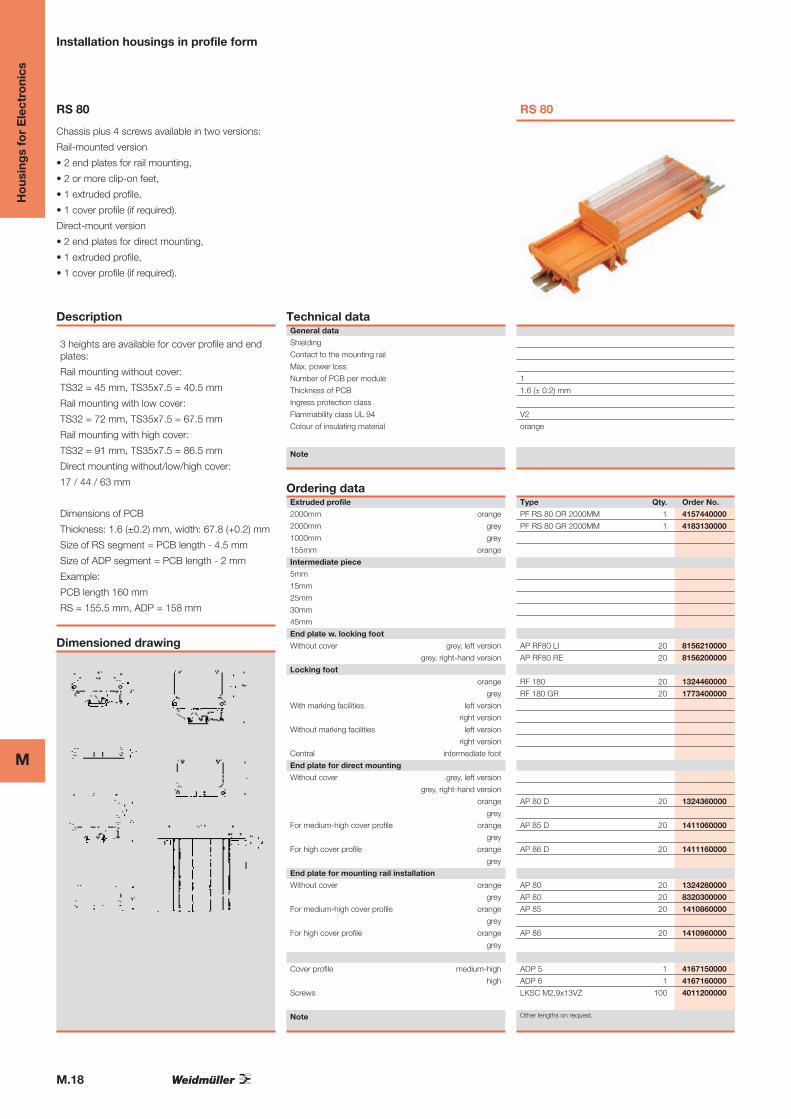
RS 80
Chassis plus 4 screws available in two versions:
Rail-mounted version
• 2 end plates for rail mounting,
• 2 or more clip-on feet,
• 1 extruded profile,
• 1 cover profile (if required).
Direct-mount version
• 2 end plates for direct mounting,
• 1 extruded profile,
• 1 cover profile (if required).
Description
3 heights are available for cover profile and endplates:
Rail mounting without cover:
TS32 = 45 mm, TS35x7.5 = 40.5 mm
Rail mounting with low cover:
TS32 = 72 mm, TS35x7.5 = 67.5 mm
Rail mounting with high cover:
TS32 = 91 mm, TS35x7.5 = 86.5 mm
Direct mounting without/low/high cover:
17 / 44 / 63 mm
Dimensions of PCB
Thickness: 1.6 (±0.2) mm, width: 67.8 (+0.2) mm
Size of RS segment = PCB length - 4.5 mm
Size of ADP segment = PCB length - 2 mm
Example:
PCB length 160 mm
RS = 155.5 mm, ADP = 158 mm
Dimensioned drawing
Technical dataGeneral data
Shielding
Contact to the mounting rail
Max. power loss
Number of PCB per module
Thickness of PCB
Ingress protection class
Flammability class UL 94
Colour of insulating material
Note
Ordering dataExtruded profile
2000mm orange
2000mm grey
1000mm grey
155mm orange
Intermediate piece
5mm
15mm
25mm
30mm
45mm
End plate w. locking foot
Without cover grey, left version
grey, right-hand version
Locking foot
orange
grey
With marking facilities left version
right version
Without marking facilities left version
right version
Central intermediate foot
End plate for direct mounting
Without cover grey, left version
grey, right-hand version
orange
grey
For medium-high cover profile orange
grey
For high cover profile orange
grey
End plate for mounting rail installation
Without cover orange
grey
For medium-high cover profile orange
grey
For high cover profile orange
grey
Cover profile medium-high
high
Screws
Note
RS 80
1
1.6 (± 0.2) mm
V2
orange
Type Qty. Order No.
PF RS 80 OR 2000MM 1 4157440000
PF RS 80 GR 2000MM 1 4183130000
AP RF80 LI 20 8156210000
AP RF80 RE 20 8156200000
RF 180 20 1324460000
RF 180 GR 20 1773400000
AP 80 D 20 1324360000
AP 85 D 20 1411060000
AP 86 D 20 1411160000
AP 80 20 1324260000
AP 80 20 8320300000
AP 85 20 1410860000
AP 86 20 1410960000
ADP 5 1 4167150000
ADP 6 1 4167160000
LKSC M2,9x13VZ 100 4011200000
Other lengths on request.
M.19
MH
ous
ing
s fo
r E
lect
roni
cs
Installation housings in profile form
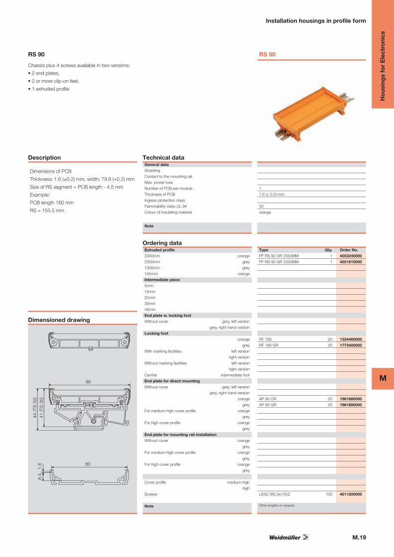
RS 90
Chassis plus 4 screws available in two versions:
• 2 end plates,
• 2 or more clip-on feet,
• 1 extruded profile
Description
Dimensions of PCB
Thickness: 1.6 (±0.2) mm, width: 79.8 (+0.2) mm
Size of RS segment = PCB length - 4.5 mm
Example:
PCB length 160 mm
RS = 155.5 mm
Dimensioned drawing
86
41 (T
S 3
5)
80
44 (T
S 3
2)8.
4 1
.8
Technical dataGeneral data
Shielding
Contact to the mounting rail
Max. power loss
Number of PCB per module
Thickness of PCB
Ingress protection class
Flammability class UL 94
Colour of insulating material
Note
Ordering dataExtruded profile
2000mm orange
2000mm grey
1000mm grey
155mm orange
Intermediate piece
5mm
15mm
25mm
30mm
45mm
End plate w. locking foot
Without cover grey, left version
grey, right-hand version
Locking foot
orange
grey
With marking facilities left version
right version
Without marking facilities left version
right version
Central intermediate foot
End plate for direct mounting
Without cover grey, left version
grey, right-hand version
orange
grey
For medium-high cover profile orange
grey
For high cover profile orange
grey
End plate for mounting rail installation
Without cover orange
grey
For medium-high cover profile orange
grey
For high cover profile orange
grey
Cover profile medium-high
high
Screws
Note
RS 90
1
1.6 (± 0.2) mm
V2
orange
Type Qty. Order No.
PF RS 90 OR 2000MM 1 4053240000
PF RS 90 GR 2000MM 1 4051810000
RF 180 20 1324460000
RF 180 GR 20 1773400000
AP 90 OR 20 1961880000
AP 90 GR 20 1961890000
LKSC M2,9x13VZ 100 4011200000
Other lengths on request.
M.20
M
Ho
usin
gs
for
Ele
ctro
nics
Installation housings in profile form
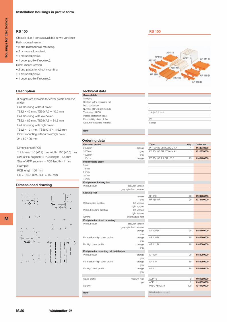
RS 100
Chassis plus 4 screws available in two versions:
Rail-mounted version
• 2 end plates for rail mounting,
• 2 or more clip-on feet,
• 1 extruded profile,
• 1 cover profile (if required).
Direct-mount version
• 2 end plates for direct mounting,
• 1 extruded profile,
• 1 cover profile (if required).
Description
3 heights are available for cover profile and endplates:
Rail mounting without cover:
TS32 = 45 mm, TS35x7.5 = 40.5 mm
Rail mounting with low cover:
TS32 = 89 mm, TS35x7.5 = 84.5 mm
Rail mounting with high cover:
TS32 = 121 mm, TS35x7.5 = 116.5 mm
Direct mounting without/low/high cover:
24 / 69 / 99 mm
Dimensions of PCB
Thickness: 1.6 (±0.2) mm, width: 100 (+0.5) mm
Size of RS segment = PCB length - 4.5 mm
Size of ADP segment = PCB length - 1 mm
Example:
PCB length 160 mm,
RS = 155.5 mm, ADP = 159 mm
Dimensioned drawing
Technical dataGeneral data
Shielding
Contact to the mounting rail
Max. power loss
Number of PCB per module
Thickness of PCB
Ingress protection class
Flammability class UL 94
Colour of insulating material
Note
Ordering dataExtruded profile
2000mm orange
2000mm grey
1000mm grey
155mm orange
Intermediate piece
5mm
15mm
25mm
30mm
45mm
End plate w. locking foot
Without cover grey, left version
grey, right-hand version
Locking foot
orange
grey
With marking facilities left version
right version
Without marking facilities left version
right version
Central intermediate foot
End plate for direct mounting
Without cover grey, left version
grey, right-hand version
orange
grey
For medium-high cover profile orange
grey
For high cover profile orange
grey
End plate for mounting rail installation
Without cover orange
grey
For medium-high cover profile orange
grey
For high cover profile orange
grey
Cover profile medium-high
high
Screws
Note
RS 100
1
1.6 (± 0.2) mm
V2
orange
Type Qty. Order No.
PF RS 100 OR 2000MM A.1 1 4144870000
PF RS 100 GR 2000MM A.1 1 4010870000
PF RS 100 A.1 OR 155.5 25 4148400000
RF 180 20 1324460000
RF 180 GR 20 1773400000
AP 100 D 20 1185160000
AP 110 D 10 1185360000
AP 111 D 10 1185560000
AP 100 20 1185060000
AP 110 10 1185260000
AP 111 10 1185460000
ADP 10 2 4169320000
ADP 11 2 4169330000
PTSC KB40X14 100 4019420000
Other lengths on request.
M.21
MH
ous
ing
s fo
r E
lect
roni
cs
Housings in terminal form
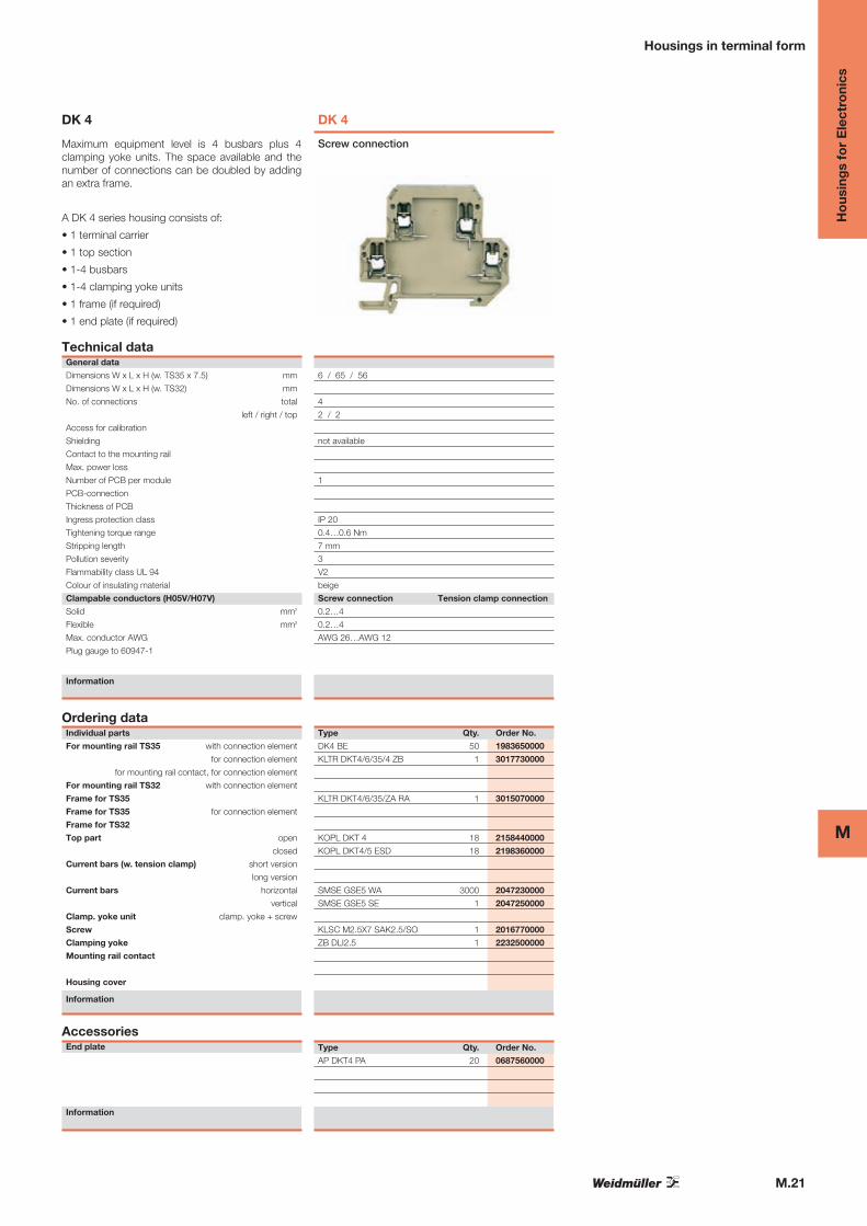
DK 4
Maximum equipment level is 4 busbars plus 4clamping yoke units. The space available and thenumber of connections can be doubled by addingan extra frame.
A DK 4 series housing consists of:
• 1 terminal carrier
• 1 top section
• 1-4 busbars
• 1-4 clamping yoke units
• 1 frame (if required)
• 1 end plate (if required)
Technical dataGeneral data
Dimensions W x L x H (w. TS35 x 7.5) mm
Dimensions W x L x H (w. TS32) mm
No. of connections total
left / right / top
Access for calibration
Shielding
Contact to the mounting rail
Max. power loss
Number of PCB per module
PCB-connection
Thickness of PCB
Ingress protection class
Tightening torque range
Stripping length
Pollution severity
Flammability class UL 94
Colour of insulating material
Clampable conductors (H05V/H07V)
Solid mm2
Flexible mm2
Max. conductor AWG
Plug gauge to 60947-1
Information
Ordering dataIndividual parts
For mounting rail TS35 with connection element
for connection element
for mounting rail contact, for connection element
For mounting rail TS32 with connection element
Frame for TS35
Frame for TS35 for connection element
Frame for TS32
Top part open
closed
Current bars (w. tension clamp) short version
long version
Current bars horizontal
vertical
Clamp. yoke unit clamp. yoke + screw
Screw
Clamping yoke
Mounting rail contact
Housing cover
Information
AccessoriesEnd plate
Information
DK 4
6 / 65 / 56
4
2 / 2
not available
1
IP 20
0.4…0.6 Nm
7 mm
3
V2
beige
Screw connection Tension clamp connection
0.2…4
0.2…4
AWG 26…AWG 12
Screw connection
Type Qty. Order No.
DK4 BE 50 1983650000
KLTR DKT4/6/35/4 ZB 1 3017730000
KLTR DKT4/6/35/ZA RA 1 3015070000
KOPL DKT 4 18 2158440000
KOPL DKT4/5 ESD 18 2198360000
SMSE GSE5 WA 3000 2047230000
SMSE GSE5 SE 1 2047250000
KLSC M2.5X7 SAK2.5/SO 1 2016770000
ZB DLI2.5 1 2232500000
Type Qty. Order No.
AP DKT4 PA 20 0687560000
M.22
M
Ho
usin
gs
for
Ele
ctro
nics
Housings in terminal form
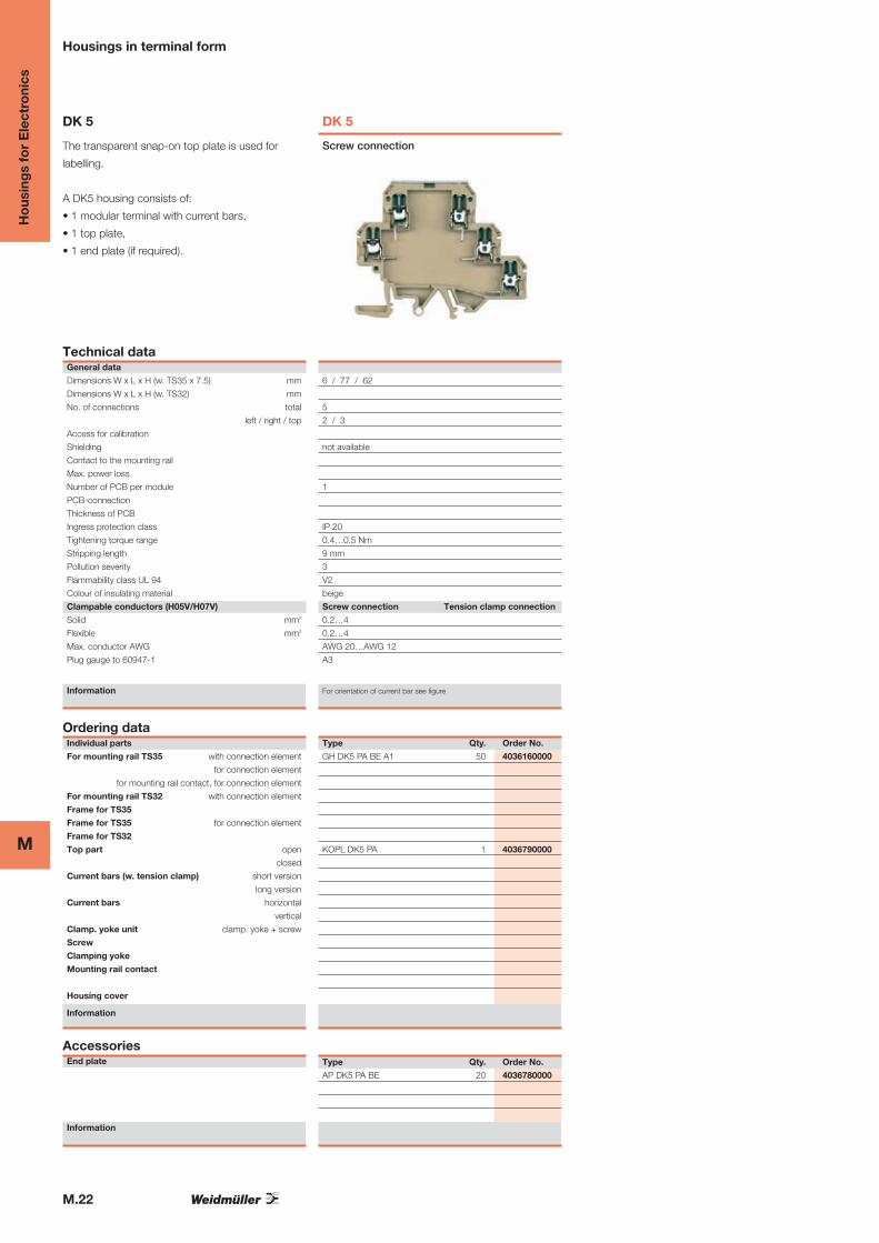
DK 5
The transparent snap-on top plate is used for
labelling.
A DK5 housing consists of:
• 1 modular terminal with current bars,
• 1 top plate,
• 1 end plate (if required).
Technical dataGeneral data
Dimensions W x L x H (w. TS35 x 7.5) mm
Dimensions W x L x H (w. TS32) mm
No. of connections total
left / right / top
Access for calibration
Shielding
Contact to the mounting rail
Max. power loss
Number of PCB per module
PCB-connection
Thickness of PCB
Ingress protection class
Tightening torque range
Stripping length
Pollution severity
Flammability class UL 94
Colour of insulating material
Clampable conductors (H05V/H07V)
Solid mm2
Flexible mm2
Max. conductor AWG
Plug gauge to 60947-1
Information
Ordering dataIndividual parts
For mounting rail TS35 with connection element
for connection element
for mounting rail contact, for connection element
For mounting rail TS32 with connection element
Frame for TS35
Frame for TS35 for connection element
Frame for TS32
Top part open
closed
Current bars (w. tension clamp) short version
long version
Current bars horizontal
vertical
Clamp. yoke unit clamp. yoke + screw
Screw
Clamping yoke
Mounting rail contact
Housing cover
Information
AccessoriesEnd plate
Information
DK 5
6 / 77 / 62
5
2 / 3
not available
1
IP 20
0.4…0.5 Nm
9 mm
3
V2
beige
Screw connection Tension clamp connection
0.2…4
0.2…4
AWG 20…AWG 12
A3
For orientation of current bar see figure
Screw connection
Type Qty. Order No.
GH DK5 PA BE A1 50 4036160000
KOPL DK5 PA 1 4036790000
Type Qty. Order No.
AP DK5 PA BE 20 4036780000

M.23
MH
ous
ing
s fo
r E
lect
roni
cs
Housings in terminal form
DK 6
The transparent snap-on top plate is used for
labelling.
A DK5 housing consists of:
• 1 modular terminal with current bars,
• 1 top plate,
• 1 end plate (if required).
Technical dataGeneral data
Dimensions W x L x H (w. TS35 x 7.5) mm
Dimensions W x L x H (w. TS32) mm
No. of connections total
left / right / top
Access for calibration
Shielding
Contact to the mounting rail
Max. power loss
Number of PCB per module
PCB-connection
Thickness of PCB
Ingress protection class
Tightening torque range
Stripping length
Pollution severity
Flammability class UL 94
Colour of insulating material
Clampable conductors (H05V/H07V)
Solid mm2
Flexible mm2
Max. conductor AWG
Plug gauge to 60947-1
Information
Ordering dataIndividual parts
For mounting rail TS35 with connection element
for connection element
for mounting rail contact, for connection element
For mounting rail TS32 with connection element
Frame for TS35
Frame for TS35 for connection element
Frame for TS32
Top part open
closed
Current bars (w. tension clamp) short version
long version
Current bars horizontal
vertical
Clamp. yoke unit clamp. yoke + screw
Screw
Clamping yoke
Mounting rail contact
Housing cover
Information
AccessoriesEnd plate
Information
DK 6
8 / 88.4 / 69
8 / 88.4 / 73
6
3 / 3
not available
1
IP 20
0.4…0.5 Nm
9 mm
3
V2
beige
Screw connection Tension clamp connection
0.2…4
0.2…4
AWG 20…AWG 12
Screw connection
Type Qty. Order No.
GH DK6 6 ANSCHL. 1 4042010000
KOPL DK6 A2 2BOHR. 1 4043950000
Type Qty. Order No.
AP DK6 PA BE 20 8324560000
M.24
M
Ho
usin
gs
for
Ele
ctro
nics
Housings in terminal form
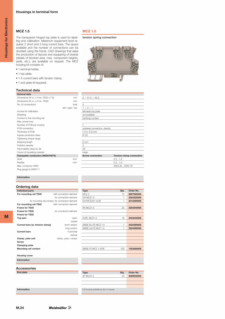
MCZ 1.5
The transparent hinged top plate is used for label-ling and calibration. Maximum equipment level re-quires 2 short and 3 long current bars. The spaceavailable and the number of connections can bedoubled using the frame. CAD drawings that easethe production of layouts and equipping of boards(details of blocked area, max. component heights,pads, etc.), are available on request. The MCZhousing kit consists of:
• 1 terminal holder,
• 1 top plate,
• 1-5 current bars with tension clamp,
• 1 end plate (if required).
Technical dataGeneral data
Dimensions W x L x H (w. TS35 x 7.5) mm
Dimensions W x L x H (w. TS32) mm
No. of connections total
left / right / top
Access for calibration
Shielding
Contact to the mounting rail
Max. power loss
Number of PCB per module
PCB-connection
Thickness of PCB
Ingress protection class
Tightening torque range
Stripping length
Pollution severity
Flammability class UL 94
Colour of insulating material
Clampable conductors (H05V/H07V)
Solid mm2
Flexible mm2
Max. conductor AWG
Plug gauge to 60947-1
Information
Ordering dataIndividual parts
For mounting rail TS35 with connection element
for connection element
for mounting rail contact, for connection element
For mounting rail TS32 with connection element
Frame for TS35
Frame for TS35 for connection element
Frame for TS32
Top part open
closed
Current bars (w. tension clamp) short version
long version
Current bars horizontal
vertical
Clamp. yoke unit clamp. yoke + screw
Screw
Clamping yoke
Mounting rail contact
Housing cover
Information
AccessoriesEnd plate
Information
MCZ 1.5
6 / 91.3 / 63.5
5
1 / 3 / 1
Movable top plate
not available
Earthing-contact
1
soldered connection, directly
1.0 (+ 0.2) mm
IP 20
6 mm
3
V0
beige
Screw connection Tension clamp connection
0.2…1.5
0.2…1.5
AWG 26…AWG 16
tension spring connection
Type Qty. Order No.
MCZ 5 10 8857560000
GH MCZ1.5 1 2224220000
GH MCZUE1.5/UE 1 2312290000
RA MCZ1.5 25 2224240000
KOPL MCZ1.5 18 2224040000
SMSE KU FE MCZ 1.5 1 2224390000
SMSE LN FE MCZ 1.5 1 2224380000
SMSE FE MCZ 1.5/PE 100 1003280000
Type Qty. Order No.
AP MCZ1.5 50 8389030000
Full housing available as set on request.
Ho
usin
gs
for
Ele
ctro
nics
M.25
M
IP68 housing
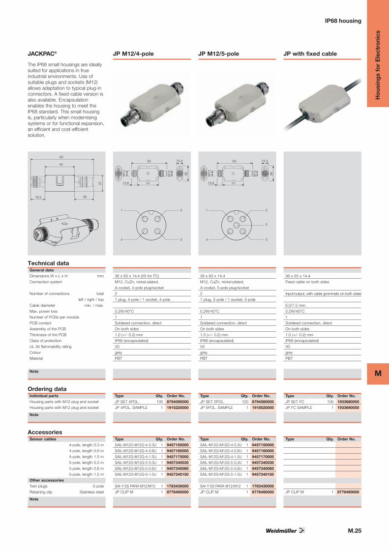
JACKPAC®
The IP68 small housings are ideally
suited for applications in true
industrial environments. Use of
suitable plugs and sockets (M12)
allows adaptation to typical plug-in
connectors. A fixed-cable version is
also available. Encapsulation
enables the housing to meet the
IP68 standard. This small housing
is, particularly when modernising
systems or for functional expansion,
an efficient and cost-efficient
solution.
83
40
2619.5
22
Technical dataGeneral data
Dimensions W x L x H mm
Connection system
Number of connections total
left / right / top
Cable diameter min. / max.
Max. power loss
Number of PCBs per module
PCB contact
Assembly of the PCB
Thickness of the PCB
Class of protection
UL 94 flammability rating
Colour
Material
Note
Ordering dataIndividual parts
Housing parts with M12 plug and socket
Housing parts with M12 plug and socket
Note
5113.8
83
M12
14.4
36
M12
1
4
2
3
Eingang
36 x 83 x 14.4 (55 for FC)
M12, CuZn, nickel-plated,
A-coded, 4-pole plug/socket
2
1 plug, 4-pole / 1 socket, 4-pole
0.2W/40°C
1
Soldered connection, direct
On both sides
1.0 (+/- 0.2) mm
IP68 (encapsulated)
V0
grey
PBT
Type Qty. Order No.
JP SET 4POL. 100 8794090000
JP 4POL. SAMPLE 1 1915220000
5113.8
83
M12
14.4
36
M12
1
4
2
3
5
Eingang
36 x 83 x 14.4
M12, CuZn, nickel-plated,
A-coded, 5-pole plug/socket
2
1 plug, 5-pole / 1 socket, 5-pole
0.2W/40°C
1
Soldered connection, direct
On both sides
1.0 (+/- 0.2) mm
IP68 (encapsulated)
V0
grey
PBT
Type Qty. Order No.
JP SET 5POL. 100 8794080000
JP 5POL. SAMPLE 1 1918520000
Eingang
36 x 55 x 14.4
Fixed cable on both sides
Input/output, with cable grommets on both sides
6.0/7.5 mm
0.2W/40°C
1
Soldered connection, direct
On both sides
1.0 (+/- 0.2) mm
IP68 (encapsulated)
V0
grey
PBT
Type Qty. Order No.
JP SET FC 100 1933680000
JP FC SAMPLE 1 1933690000
JP M12/4-pole JP M12/5-pole JP with fixed cable
AccessoriesSensor cables
4-pole, length 0.3 m
4-pole, length 0.6 m
4-pole, length 1.5 m
5-pole, length 0.3 m
5-pole, length 0.6 m
5-pole, length 1.5 m
Other accessories
Twin plugs 5-pole
Retaining clip Stainless steel
Note
Type Qty. Order No.
SAIL-M12G-M12G-4-0.3U 1 9457150000
SAIL-M12G-M12G-4-0.6U 1 9457160000
SAIL-M12G-M12G-4-1.5U 1 9457170000
SAIL-M12G-M12G-5-0.3U 1 9457340030
SAIL-M12G-M12G-5-0.6U 1 9457340060
SAIL-M12G-M12G-5-1.5U 1 9457340150
SAI-Y-5S PARA M12/M12 1 1783430000
JP CLIP M 1 8778490000
Type Qty. Order No.
SAIL-M12G-M12G-4-0.3U 1 9457150000
SAIL-M12G-M12G-4-0.6U 1 9457160000
SAIL-M12G-M12G-4-1.5U 1 9457170000
SAIL-M12G-M12G-5-0.3U 1 9457340030
SAIL-M12G-M12G-5-0.6U 1 9457340060
SAIL-M12G-M12G-5-1.5U 1 9457340150
SAI-Y-5S PARA M12/M12 1 1783430000
JP CLIP M 1 8778490000
Type Qty. Order No.
JP CLIP M 1 8778490000
M.26
M
Ho
usin
gs
for
Ele
ctro
nics


