Embed Size (px)
Citation preview
1 / 21
LONGi Solar Technology Co., Ltd. TEL:+86-400-9696199 Fax: +86-29-86686228
en.longi-solar.com
Installation Manual for LONGi Solar Modules
1000V Photovoltaic Modules
Safety Notes
This manual elaborates on installation and safety use information for Solar power generating
modules (hereinafter referred to as module) of LONGi Green Energy Technology Co., Ltd..
(hereinafter referred to as LONGi Solar). Please abide by all safety precautions in this guide and
local regulations.
Installation of modules requires professional skills and knowledge and is to be carried out by
qualified personnel. Please read this manual carefully before installing and using this module.
Installation personnel shall get familiar with mechanical and electrical requirements of this system.
Please keep this manual properly as reference for future maintenance or upkeep, or for sales and
treatment of modules.
If you have any questions, please contact LONGi global quality and customer service department
for further interpretation.
2 / 21
LONGi Solar Technology Co., Ltd. TEL:+86-400-9696199 Fax: +86-29-86686228
en.longi-solar.com
Contents
1 Introduction ................................................................................................................................................ 3
2 Laws and regulations ................................................................................................................................... 3
3 General Information .................................................................................................................................... 4
3.1 Module Identification ............................................................................................................................ 4
3.2 Regular Safety ........................................................................................................................................ 5
3.3 Electric Performance Safety ................................................................................................................... 6
3.4 Operation Safety .................................................................................................................................... 6
3.5 Fire Safety .............................................................................................................................................. 7
4 Installation conditions ................................................................................................................................. 8
4.1 Installation site and working environments .......................................................................................... 8
4.2 Selection of Tilt Angles ........................................................................................................................... 9
5 Mechanical Installation ............................................................................................................................... 9
5.1 Regular Requirements ............................................................................................................................ 9
5.2 Installation Methods ............................................................................................................................ 10
6 Electric installation .................................................................................................................................... 15
6.1 Electric performance ............................................................................................................................ 15
6.2 Cables and Connecting Wires .............................................................................................................. 16
6.3 Connector ............................................................................................................................................. 17
6.4 Bypass Diode ........................................................................................................................................ 17
7 Grounding ................................................................................................................................................. 18
7.1 Grounding by grounding clamp ........................................................................................................... 18
7.2 Grounding by Unoccupied Mounting Holes ......................................................................................... 19
7.3 Other Third Party Grounding Devices .................................................................................................. 20
8 Operation and Maintenance ..................................................................................................................... 20
8.1 Cleaning ................................................................................................................................................ 20
8.2 Inspection of Module Appearance ....................................................................................................... 21
8.3 Inspection of Connectors and Cables ................................................................................................... 21
3 / 21 en.longi-solar.com LONGi Solar Technology Co., Ltd.
TEL:+86-400-9696199 Fax: +86-29-86686228
1 Introduction
Thank You for Choosing LONGi Solar PV Modules!
This installation manual includes important electric and mechanical installation instructions.
Please understand these instructions before installing LONGi modules. In addition, this manual
also contains some safety instructions that you have to know. All contents in this manual are
intellectual properties of LONGi Solar which originates from the long‐term technical
exploration and accumulated experience.
This installation manual does not entail any explicit or implicit quality warranty and does not
stipulate on compensation schemes for losses, module damages or other costs caused by or
related to module installation, operation, utilization and maintenance process. If patent rights
or the third party rights are infringed by use of modules, LONGi Solar shall not take any
responsibility. LONGi Solar reserves the rights for modifying the product manual or installation
manual without notice in advance.
If customers fail to install modules as per the requirements set forth in this manual, the quality
warranty provided for customers during sales shall become invalid. In addition, suggestions in
this manual are to improve safety of module installation, which are proved by tests and
practices. Please provide this manual to owners of the solar PV power systems for reference
and instruct them in the requirements and suggestions relevant to safety, operation and
maintenance.
2 Laws and regulations
Mechanical and electrical installation of Solar PV Modules shall be carried out as per the
relevant laws and regulations such as electric law, building law and electric connecting
requirements. These laws and regulations vary in accordance with different installation sites,
such as building roof installation, vehicle‐mounted application. The relevant requirements may
also vary in accordance with installation system voltage, DC or AC electricity. Please contact
4 / 21 en.longi-solar.com LONGi Solar Technology Co., Ltd.
TEL:+86-400-9696199 Fax: +86-29-86686228
the local authorities for specific clauses.
3 General Information
3.1 Module Identification
Each module is pasted with 3 labels providing information as follows:
1. Nameplate: It describes product type, standard rated power, rated current, rated voltage,
open circuit voltage, short circuit current under testing conditions, certification indicator,
maximum system voltage, etc.
2. Current Level Label: Divide modules as per the maximum current into 3 levels: H, M or L
(H is the highest current level). The most recommended practice is to install modules with the
same current level (such as H) in a string during the installation.
3. Serial Number: Each module has a unique serial number which is solidified inside the
module permanently and it can be seen at the front top of the module. This serial number is put
in before lamination of the module. In addition, you can find the same serial number on the
module nameplate.
5 / 21 en.longi-solar.com LONGi Solar Technology Co., Ltd.
TEL:+86-400-9696199 Fax: +86-29-86686228
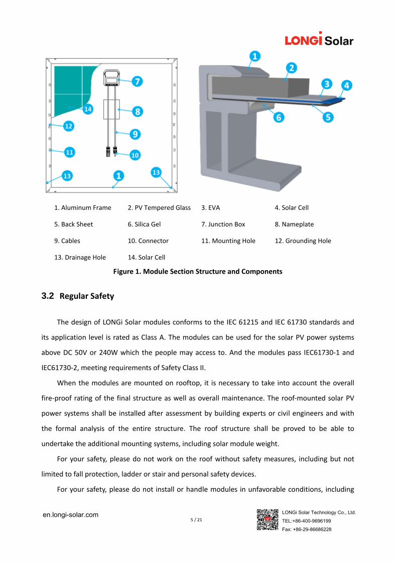
1. Aluminum Frame 2. PV Tempered Glass 3. EVA 4. Solar Cell
5. Back Sheet 6. Silica Gel 7. Junction Box 8. Nameplate
9. Cables 10. Connector 11. Mounting Hole 12. Grounding Hole
13. Drainage Hole 14. Solar Cell
Figure 1. Module Section Structure and Components
3.2 Regular Safety
The design of LONGi Solar modules conforms to the IEC 61215 and IEC 61730 standards and
its application level is rated as Class A. The modules can be used for the solar PV power systems
above DC 50V or 240W which the people may access to. And the modules pass IEC61730‐1 and
IEC61730‐2, meeting requirements of Safety Class II.
When the modules are mounted on rooftop, it is necessary to take into account the overall
fire‐proof rating of the final structure as well as overall maintenance. The roof‐mounted solar PV
power systems shall be installed after assessment by building experts or civil engineers and with
the formal analysis of the entire structure. The roof structure shall be proved to be able to
undertake the additional mounting systems, including solar module weight.
For your safety, please do not work on the roof without safety measures, including but not
limited to fall protection, ladder or stair and personal safety devices.
For your safety, please do not install or handle modules in unfavorable conditions, including
6 / 21 en.longi-solar.com LONGi Solar Technology Co., Ltd.
TEL:+86-400-9696199 Fax: +86-29-86686228
but not limited to strong wind or gust, damp or sandy rooftops.
3.3 Electric Performance Safety
Solar modules produce DC electricity in the sunlight, so there will cause hazards such as
electric shock or burning when the module cables or metals are touched by human or animals.
30V DC voltage or higher voltage can be fatal to human or animals.
In case that no load or external circuit is connected, the modules will also produce voltage.
Please use insulation tools and wear rubber gloves when you handle the modules in the sunlight.
Solar PV Modules do not have switch. Solar PV Modules can only stop work when they are
kept from sunlight or covered by cloth, carton board or light‐proof materials or when front sides
of modules are placed on smooth and flat surface.
To avoid electric arc or electric shock, please do not break down electric connection in
loaded conditions. Wrong connections will also lead to electric arc or shock. Keep connectors dry
and clean and make sure that they are in good condition. Do not insert other metal objects into
the connectors or carry out electric connection by any other means.
Snow and water in surrounding environments will intensify light reflection and lead to
increase of current and output power. And the module voltage and power will increase at a low
temperature.
If module glass or encapsulating materials are damaged, please wear personal safety
devices and isolate modules from the circuit.
Work shall be only carried out in dry conditions with dry tools. Do not operate the modules
when modules are wet unless you wear the proper protection devices against electric shock.
Please clean modules as per the relevant instructions in this manual.
3.4 Operation Safety
Do not open LONGi module’s package during transportation and storage, unless the
modules arrive at the installation site.
Protect the package well and avoid any damage to the package. Do not make packaged
modules on pallet fall directly.
7 / 21 en.longi-solar.com LONGi Solar Technology Co., Ltd.
TEL:+86-400-9696199 Fax: +86-29-86686228
Do not exceed the tier limitation indicated on the packaging cartons when stacking up
modules.
Put packaging cartons in the ventilated, rain‐proof and dry places before unpacking
modules.
Open LONGi’s packaging carton as per unpacking instructions provided by LONGi Solar.
Do not hold the junction box or cables to lift the entire module in any case.
Standing or walking on modules is strictly prohibited.
Do not drop one module onto another module.
To avoid any damage to the front glass of a module, do not put heavy objects on it.
Handle carefully when placing modules on a surface and especially at corners.
Do not try to dismantle any module or remove nameplate or parts of modules.
Do not brush paints or apply any adhesive on the surface of modules.
Do not damage, carve or scratch back film of modules.
Do not drill on the frames of modules, which may reduce the frames’ loading capacity or
lead to corrosion of the frames.
Do not scratch anodized coating of aluminum frame except for grounding connection.
Scratch may lead to corrosion of the frame and reduce its loading capacity.
Do not on your own repair glass or modules which the back film is damaged.
3.5 Fire Safety
Please consult local laws and regulations before installing modules and abide by
requirements about the fire safety of buildings. The fire‐proof rating of LONGi Solar modules is
Class C in accordance with IEC61730‐2 standard.
The rooftop shall be coated with a layer of fireproof materials conforming to such rating for
before the roof‐mounted installation is carried out. Make sure that the back sheet and the
mounting surface are fully ventilated.
The difference between rooftop structures and installation methods will affect fireproof
performance of buildings. Improper installation may cause fire hazards.
To guarantee the fire‐proof rating, the module frame shall be at least 10cm from the rooftop.
Please choose proper module accessories such as fuses, circuit breakers and grounding
8 / 21 en.longi-solar.com LONGi Solar Technology Co., Ltd.
TEL:+86-400-9696199 Fax: +86-29-86686228
connectors as per local laws or regulations.
Please do not use modules if there are exposed inflammable gases nearby.
4 Installation conditions
4.1 Installation site and working environments
The modules can only be used on earth but not in outer space.
Do not focalize the sunlight with mirrors or magnifying glass onto modules.
LONGi Solar modules shall be installed on proper buildings or other appropriate places (such
as ground, garage, building outer wall, rooftop, solar tracking system) but shall not be installed on
any mobile vehicle.
Do not install modules at the places that may be submerged by water.
LONGi Solar recommends that modules are installed in the environment with the ambient
temperature of ‐20℃ to 46℃ which is the monthly average highest and lowest temperature of
the installation sites. The extreme ambient temperature for modules ranges from ‐40℃ to 85℃.
Make sure that the installed modules do not bear wind or snow load that exceeds the
permissible maximum load.
Modules shall be installed in a place free from shades throughout the year. Make sure there
are no obstacles blocking sunlight at the installation site.
Lightning and thunder protection shall be provided for modules installed in places with
frequent lightning and thunders.
Do not install modules in places where inflammable gases are possibly emitted.
Modules shall not be used in the environment with frequent hail, snow, blowing sand, smoke
dust, polluted air and soot or in places with strong corrosive substances such as salt, salty mist,
saline, active chemical steam, acid rain, or other substances corroding modules, affecting module
safety or performance.
Please take protective measures to make reliable and safe installation of modules in harsh
environments such as heavy snow, freezing cold and strong wind or places close to waters and
islands with salty mist or deserts, etc.
9 / 21 en.longi-solar.com LONGi Solar Technology Co., Ltd.
TEL:+86-400-9696199 Fax: +86-29-86686228
LONGi Solar modules have passed IEC61701 salty mist corrosion test, but the corrosion may
occur at the joints connecting the module frame and the mounting system or grounding joints.
LONGi modules can be installed less than 500mm but more than 50m from the seaside but
stainless steel or aluminum shall be applied to contact solar PV Modules. And anti‐corrosion
protection shall be furnished for installation joints. See the installation requirements in Seaside
Installation Instructions by LONGi Solar.
4.2 Selection of Tilt Angles
Tilt angle of module: the included angle between module surface and horizontal surface. The
module will obtain the optimal power output when its front surface is in direct sunlight.
Modules shall be mounted towards the south in the north hemisphere and towards north in
the south hemisphere.
A specific installation angle shall be determined as per the installation guide for standard
solar PV modules or advices from solar PV module installers.
LONGI suggests that the tilt angle for the module installation shall not be less than 10° so that
the dust on the module surface can be flushed away easily by rainfall and times of cleaning
module can be reduced accordingly. And it also facilitates the drainage of collected water on the
module surface and avoids water print on the glass due to long time water collection which may
further affect module appearance and performance.
5 Mechanical Installation
5.1 Regular Requirements
Make sure that module installation methods and mounting system are solid enough to bear
the estimated load, which is the assurance that the mounting system installer must provide. The
mounting system shall be inspected and tested by a third party testing institution with static
mechanics analysis capacity in accordance with local national or international standards such as
DIN1055 or its equivalent.
The mounting system shall be made from durable, corrosion‐resistant, ultraviolet‐proof
10 / 21 en.longi-solar.com LONGi Solar Technology Co., Ltd.
TEL:+86-400-9696199 Fax: +86-29-86686228
materials.
Modules shall be fixed on the mounting system firmly.
Use the elevated mounting systems in places with heavy snow so the lowest point of modules
shall not be covered by snow for a long time. In addition, make the lowest point high enough so as
to avoid shading of plants and plants or damage by blowing sands and stones.
If modules are installed on mounting systems parallel to the rooftop or wall, the minimum
spacing between the module frame and the rooftop or wall shall be 10cm for ventilation so as to
prevent the damage of the module’s cables.
Drilling holes on the glass or frame of modules is strictly prohibited.
Make sure that the building is suitable for installation before modules are mounted on
rooftop. Moreover, seal the permeable positions of rooftop properly to prevent leakage of
rainwater.
The module frame has thermal expansion and cold contraction so the frame interval between
two adjoining modules shall be no less than 10mm.
Make sure that the back sheet of the module will not contact the mounting system behind
the module or any building structure, especially when the module surface bears pressure.
The maximum static load of modules is: 2400Pa (equal to wind load) for backside and 5400Pa
or 2400Pa (equal to snow load or wind load) for front side. This depends on the installation type
(please refer to the installation method below).
Module installation methods cannot cause electrochemical corrosion between module
aluminum frame and other metals. The electric potential difference of contacting metals shall not
exceed 0.6V as is recommended in the Appendix of UL1703 Flat Plate Photovoltaic Modules and
Panels.
Modules can be installed horizontally or vertically.
5.2 Installation Methods
Module and mounting system can be fixed by mounting holes, clamps or embedded systems.
The installation shall be carried out as the following illustrations and suggestions. If the installation
methods is different, please consult LONGi Solar and obtain approval of LONGi Solar. Otherwise,
the modules may be damaged and the quality warranty is deemed null and void.
11 / 21 en.longi-solar.com LONGi Solar Technology Co., Ltd.
TEL:+86-400-9696199 Fax: +86-29-86686228
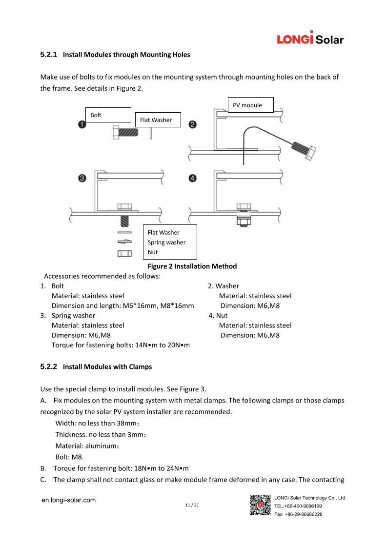
5.2.1 Install Modules through Mounting Holes
Make use of bolts to fix modules on the mounting system through mounting holes on the back of
the frame. See details in Figure 2.
Figure 2 Installation Method
Accessories recommended as follows:
1. Bolt 2. Washer
Material: stainless steel Material: stainless steel
Dimension and length: M6*16mm, M8*16mm Dimension: M6,M8
3. Spring washer 4. Nut
Material: stainless steel Material: stainless steel
Dimension: M6,M8 Dimension: M6,M8
Torque for fastening bolts: 14N•m to 20N•m
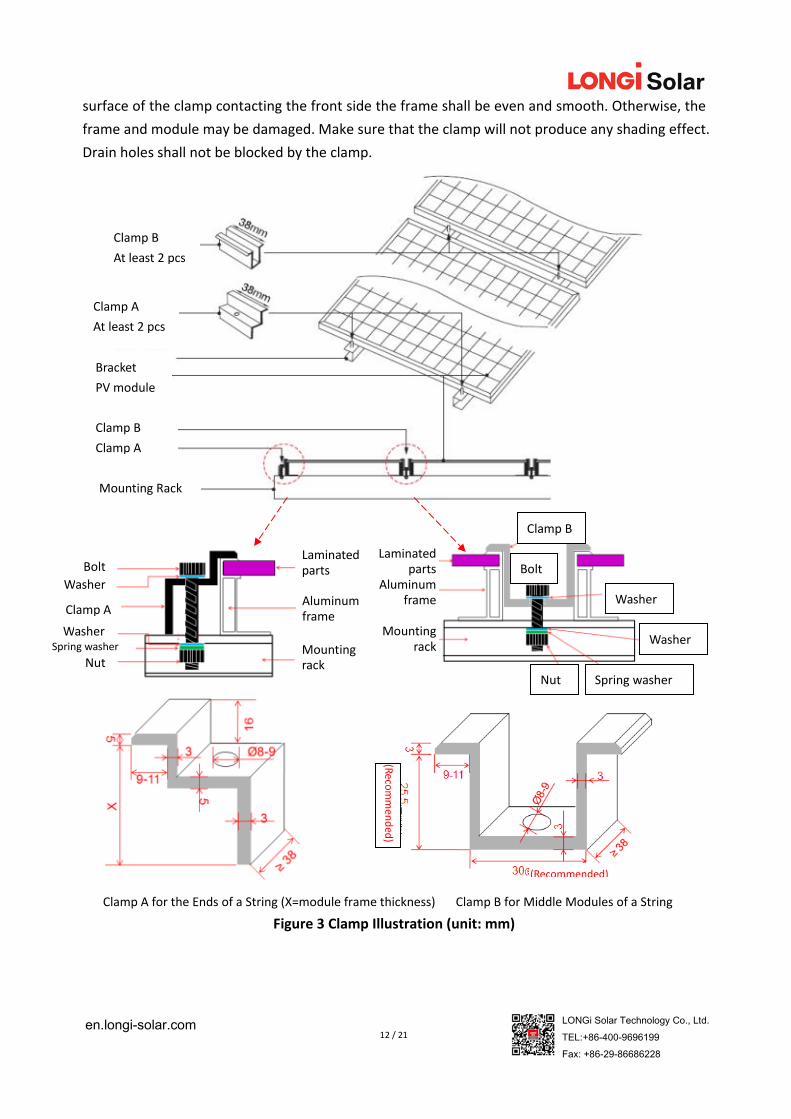
5.2.2 Install Modules with Clamps
Use the special clamp to install modules. See Figure 3.
A. Fix modules on the mounting system with metal clamps. The following clamps or those clamps
recognized by the solar PV system installer are recommended.
Width: no less than 38mm;
Thickness: no less than 3mm;
Material: aluminum;
Bolt: M8.
B. Torque for fastening bolt: 18N•m to 24N•m
C. The clamp shall not contact glass or make module frame deformed in any case. The contacting
Bolt Flat Washer
PV module
Flat Washer
Spring washer
Nut
12 / 21 en.longi-solar.com LONGi Solar Technology Co., Ltd.
TEL:+86-400-9696199 Fax: +86-29-86686228
surface of the clamp contacting the front side the frame shall be even and smooth. Otherwise, the
frame and module may be damaged. Make sure that the clamp will not produce any shading effect.
Drain holes shall not be blocked by the clamp.
Clamp A for the Ends of a String (X=module frame thickness) Clamp B for Middle Modules of a String
Figure 3 Clamp Illustration (unit: mm)
Clamp B
At least 2 pcs
Clamp A
At least 2 pcs
Bracket
PV module
Clamp B
Clamp A
Mounting Rack
Bolt
Washer
Laminated parts
Laminated parts
Aluminum frame
Mounting rack
Clamp B
Bolt
Washer
Washer
Nut Spring washer
Aluminum frame
Mounting rack
Clamp A
Nut
Washer Spring washer
(Recommended)
(Reco
mmen
ded)
13 / 21 en.longi-solar.com LONGi Solar Technology Co., Ltd.
TEL:+86-400-9696199 Fax: +86-29-86686228
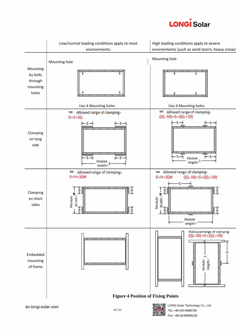
5.2.3 Positions of Fixing Points
Low/normal loading conditions apply to most environments: the maximum static
pressure on the backside of the module is 2400pa (equal to wind load) and the
maximum static pressure on the front side is 2400pa (equal to wind load and snow
load).
High loading conditions apply to severe environments (such as wind storm, heavy
snow): the maximum static pressure on the backside of the module is 2400pa (equal to
wind load) and the maximum static pressure on the front side is 5400pa (equal to wind
load and snow load), which is the highest requirement on pressure in the IEC standards.
For dynamic loads such as gust, it needs to triple the safety coefficient. That is that the
maximum gust pressure is ±800Pa and the wind speed is less than 130 Km/hour.
14 / 21 en.longi-solar.com LONGi Solar Technology Co., Ltd.
TEL:+86-400-9696199 Fax: +86-29-86686228
Low/normal loading conditions apply to most
environments:
High loading conditions apply to severe
environments (such as wind storm, heavy snow):
Mounting
by bolts
through
mounting
holes
Mounting hole
Mounting hole
Use 4 Mounting holes Use 4 Mounting holes
Clamping
on long
side
Clamping
on short
sides
Embedded
mounting
of frame
Figure 4 Position of Fixing Points
15 / 21 en.longi-solar.com LONGi Solar Technology Co., Ltd.
TEL:+86-400-9696199 Fax: +86-29-86686228
6 Electric installation
6.1 Electric performance
The electric performance parameters of the module, such as Isc, Voc and Pmax (nominal
values) have ±3% tolerance with those under the standard testing conditions: irradiance of 1000
W/m2, cell temperature of 25℃ and AM (air mass) 1.5;
In normal conditions, the current and voltage values produced by the module are a little bit
higher than those under standard testing conditions. Therefore, when you determine the
accessories of solar PV power system, such as rated voltage, cable capacity, fuse capacity and the
parameters relevant to the module power output, it shall be 1.25 times the current of short circuit
(Isc) and voltage of open circuit (Voc) before the use of the accessories.
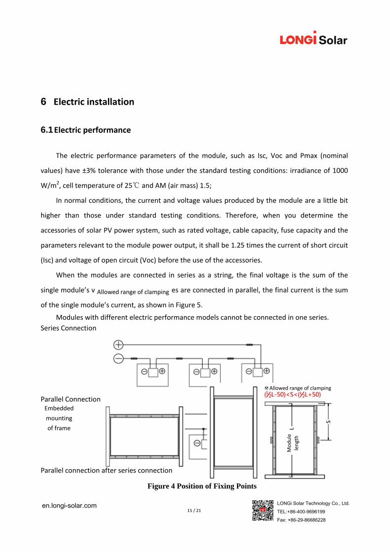
When the modules are connected in series as a string, the final voltage is the sum of the
single module’s voltage. When the modules are connected in parallel, the final current is the sum
of the single module’s current, as shown in Figure 5.
Modules with different electric performance models cannot be connected in one series.
Series Connection
Parallel Connection
Parallel connection after series connection
Allowed range of clamping
Embedded
mounting
of frame
Figure 4 Position of Fixing Points
Allowed range of clamping
Module
length
16 / 21 en.longi-solar.com LONGi Solar Technology Co., Ltd.
TEL:+86-400-9696199 Fax: +86-29-86686228
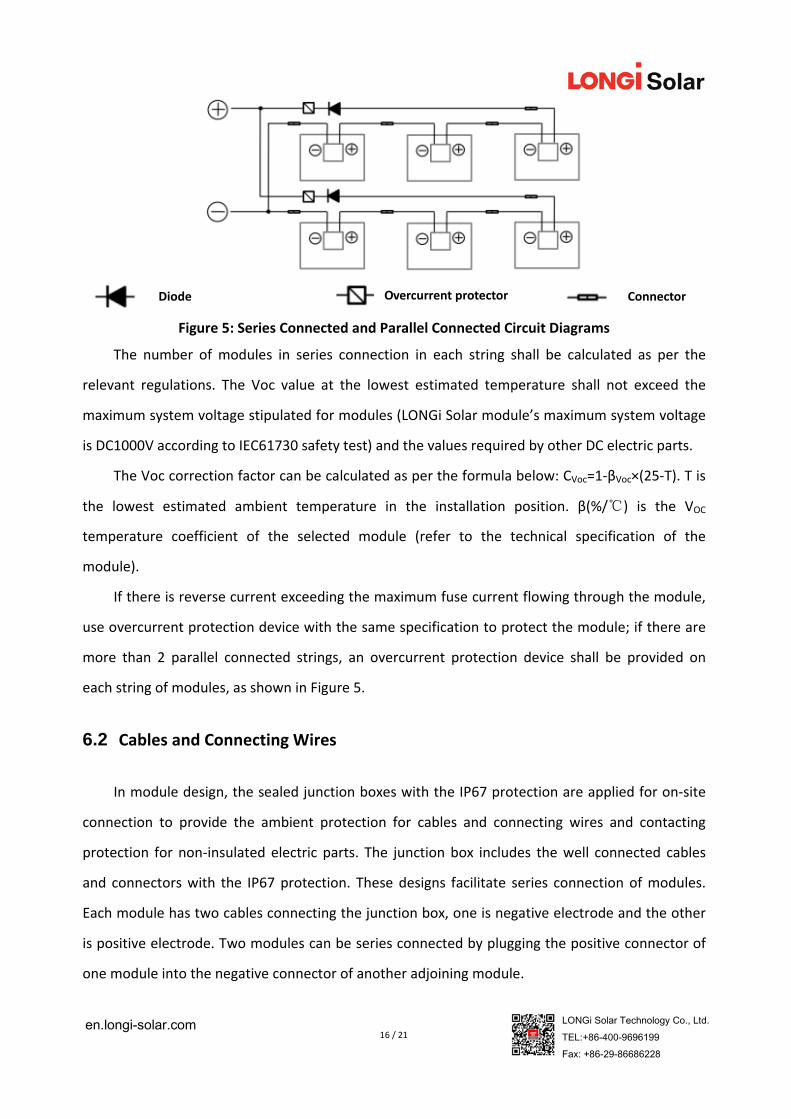
Figure 5: Series Connected and Parallel Connected Circuit Diagrams
The number of modules in series connection in each string shall be calculated as per the
relevant regulations. The Voc value at the lowest estimated temperature shall not exceed the
maximum system voltage stipulated for modules (LONGi Solar module’s maximum system voltage
is DC1000V according to IEC61730 safety test) and the values required by other DC electric parts.
The Voc correction factor can be calculated as per the formula below: CVoc=1‐βVoc×(25‐T). T is
the lowest estimated ambient temperature in the installation position. β(%/℃) is the VOC
temperature coefficient of the selected module (refer to the technical specification of the
module).
If there is reverse current exceeding the maximum fuse current flowing through the module,
use overcurrent protection device with the same specification to protect the module; if there are
more than 2 parallel connected strings, an overcurrent protection device shall be provided on
each string of modules, as shown in Figure 5.
6.2 Cables and Connecting Wires
In module design, the sealed junction boxes with the IP67 protection are applied for on‐site
connection to provide the ambient protection for cables and connecting wires and contacting
protection for non‐insulated electric parts. The junction box includes the well connected cables
and connectors with the IP67 protection. These designs facilitate series connection of modules.
Each module has two cables connecting the junction box, one is negative electrode and the other
is positive electrode. Two modules can be series connected by plugging the positive connector of
one module into the negative connector of another adjoining module.
Diode Overcurrent protector Connector
17 / 21 en.longi-solar.com LONGi Solar Technology Co., Ltd.
TEL:+86-400-9696199 Fax: +86-29-86686228
The module connecting cables shall withstand the maximum short circuit current of the
module. The special sunlight resistant cables for solar PV systems shall be used.
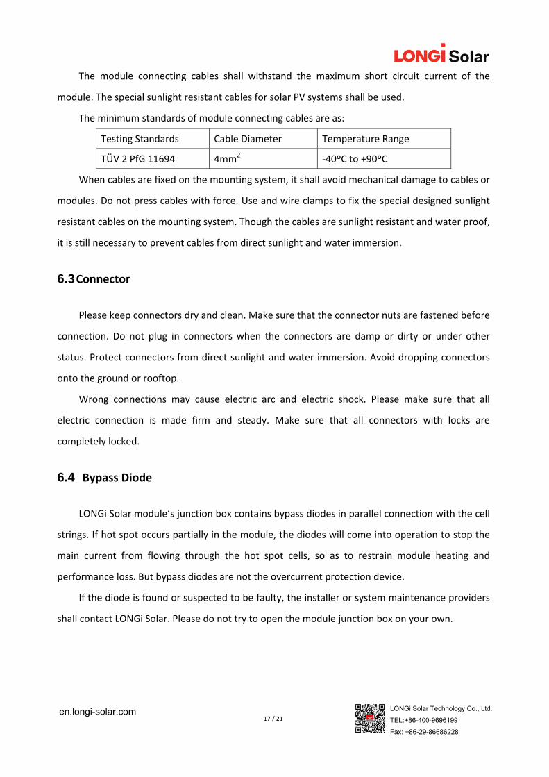
The minimum standards of module connecting cables are as:
Testing Standards Cable Diameter Temperature Range
TÜV 2 PfG 11694 4mm2 ‐40ºC to +90ºC
When cables are fixed on the mounting system, it shall avoid mechanical damage to cables or
modules. Do not press cables with force. Use and wire clamps to fix the special designed sunlight
resistant cables on the mounting system. Though the cables are sunlight resistant and water proof,
it is still necessary to prevent cables from direct sunlight and water immersion.
6.3 Connector
Please keep connectors dry and clean. Make sure that the connector nuts are fastened before
connection. Do not plug in connectors when the connectors are damp or dirty or under other
status. Protect connectors from direct sunlight and water immersion. Avoid dropping connectors
onto the ground or rooftop.
Wrong connections may cause electric arc and electric shock. Please make sure that all
electric connection is made firm and steady. Make sure that all connectors with locks are
completely locked.
6.4 Bypass Diode
LONGi Solar module’s junction box contains bypass diodes in parallel connection with the cell
strings. If hot spot occurs partially in the module, the diodes will come into operation to stop the
main current from flowing through the hot spot cells, so as to restrain module heating and
performance loss. But bypass diodes are not the overcurrent protection device.
If the diode is found or suspected to be faulty, the installer or system maintenance providers
shall contact LONGi Solar. Please do not try to open the module junction box on your own.
18 / 21 en.longi-solar.com LONGi Solar Technology Co., Ltd.
TEL:+86-400-9696199 Fax: +86-29-86686228
7 Grounding
In design of modules, the anodized corrosion resistant aluminum frame is used for rigid
support. For safety and protecting modules from damage by lightning and static electricity, the
module frame shall be grounded.
The grounding device shall be in full contact with inner side of the aluminum frame and
penetrate the oxidized coating on the frame surface.
Do not drill additional grounding holes on the module frame.
To get the optimal power output, LONGi Solar suggests that DC negative pole of the solar
PV array shall be grounded during the installation. Otherwise, the system’s output power may
be decreased.
The grounding methods of modules shall not cause electrochemical corrosion between the
aluminum frame and other metals. The electric potential difference of contacting metals shall not
exceed 0.6V as is recommended in the Appendix of UL1703 Flat Plate Photovoltaic Modules and
Panels.
The grounding holes on the frame are already drilled in advance and marked with grounding
signs. These grounding holes are only used for grounding but not for module installation.
The grounding methods as follows are allowed:
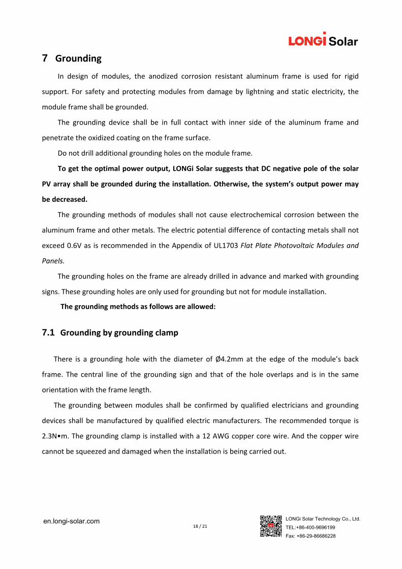
7.1 Grounding by grounding clamp
There is a grounding hole with the diameter of Ø4.2mm at the edge of the module’s back
frame. The central line of the grounding sign and that of the hole overlaps and is in the same
orientation with the frame length.
The grounding between modules shall be confirmed by qualified electricians and grounding
devices shall be manufactured by qualified electric manufacturers. The recommended torque is
2.3N•m. The grounding clamp is installed with a 12 AWG copper core wire. And the copper wire
cannot be squeezed and damaged when the installation is being carried out.
19 / 21 en.longi-solar.com LONGi Solar Technology Co., Ltd.
TEL:+86-400-9696199 Fax: +86-29-86686228
Figure 6 Installation of Grounding Clamp
Note: TYCO. 1954381‐1 (recommended) is used in the above figures
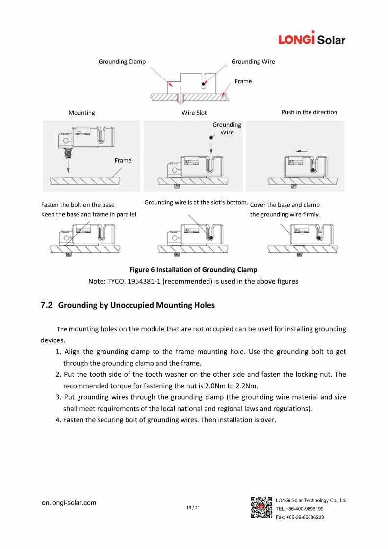
7.2 Grounding by Unoccupied Mounting Holes
The mounting holes on the module that are not occupied can be used for installing grounding
devices.
1. Align the grounding clamp to the frame mounting hole. Use the grounding bolt to get
through the grounding clamp and the frame.
2. Put the tooth side of the tooth washer on the other side and fasten the locking nut. The
recommended torque for fastening the nut is 2.0Nm to 2.2Nm.
3. Put grounding wires through the grounding clamp (the grounding wire material and size
shall meet requirements of the local national and regional laws and regulations).
4. Fasten the securing bolt of grounding wires. Then installation is over.
Grounding Clamp Grounding Wire
Frame
Mounting Wire Slot Push in the direction
Frame
Fasten the bolt on the base
Keep the base and frame in parallel
Grounding wire is at the slot’s bottom. Cover the base and clamp
the grounding wire firmly.
Grounding Wire
20 / 21 en.longi-solar.com LONGi Solar Technology Co., Ltd.
TEL:+86-400-9696199 Fax: +86-29-86686228
Figure 7 Installation Method
7.3 Other Third Party Grounding Devices
The third party grounding devices can be used for grounding of LONGi Solar modules but such
a grounding installation shall be proved to be reliable. The grounding devices shall be operated as
per instructions of the manufacturer.
8 Operation and Maintenance
Carry out regular inspection of and maintenance for the modules, which is the user’s
responsibility and obligation particularly within the quality warranty period. The user shall inform
the supplier in written form within two weeks when the modules are found to be faulty or
damaged.
8.1 Cleaning
The accumulated dust on the module surface glass will decrease the power output and lead
to the hot spot on the partial module, so will the industrial waste water and bird droppings. The
degree of influence is determined by transparency of wastes. Small amounts of dust will affect
sunlight strength and evenness but is not dangerous and the output power will not be reduced
remarkably.
During operation of a module, there shall be no other objects projecting shades on the partial
or the entire module, including other modules, mounting system, bird droppings, dust, dirt or
plants. These will reduce output power extremely. LONGi Solar suggests that the module surface
shall not be sheltered or blocked at any time.
The frequency of cleaning depends on the rate of dust accumulation. Normally, the rainwater
will clean the module surface and the cleaning frequency is reduced therefore. It is suggested to
Frame
Grounding wire
Securing bolt for the grounding wire
Grounding bolt
Fixing end of grounding clamp
Tooth washer
Locking nut
21 / 21 en.longi-solar.com LONGi Solar Technology Co., Ltd.
TEL:+86-400-9696199 Fax: +86-29-86686228
use wet sponge or soft dust cloth containing water to wipe the glass surface. Do not use cleanser
containing acid and alkaline to clean modules.
8.2 Inspection of Module Appearance
Check module appearance defects visually, especially:
1. Cracks on the module glass.
2. Corrosion at welding joints of the solar cells’ bus bar: it is caused by water vapor ingress
into the module due to damage of encapsulating materials during transportation or installation.
3. Check whether there is burning traces on the module’s back sheet.
8.3 Inspection of Connectors and Cables
It is suggested to carry out a preventive inspection once every 6 months:
1. Check the seal of connectors and firmness of cable connection.
2. Check whether the sealant of the junction box cracks or have any gap.
LONGi Green Energy Technology Co., Ltd.
Block B, No.8989 Shangji Road, Xi'an Economic and Technological Development Zone, Xi'an,
Shaanxi, China.
Tel: +86‐ 4009696199 Fax: +86‐29‐86686228
Postal code: 710018 Official website: en.longi‐solar.com


![Photovoltaic Modules - Text of Proposted Regulations 21, 2017 · 25 (underline). 26 . 27 . 28 . 29 . 30 [Photovoltaic (PV) Modules – Universal Waste Management Regulations] Department](https://img.pdfslide.net/doc/110x75/5acd2f147f8b9a875a8d7f0d/photovoltaic-modules-text-of-proposted-21-201725-underline-26-27-28-.jpg)


![[Photovoltaic modules (PV modules) – Universal Waste ... · 24/12/2019 · [Photovoltaic modules (PV modules) – Universal Waste Management ] Proposed Regulation Text R-2017-04](https://img.pdfslide.net/doc/110x75/5f4ce350b9360a33274df70d/photovoltaic-modules-pv-modules-a-universal-waste-24122019-photovoltaic.jpg)


![[Photovoltaic modules (PV modules) – Universal Waste ... · 2/10/2019 · [Photovoltaic modules (PV modules) – Universal Waste Management ] Proposed Regulation Text R-2017-04](https://img.pdfslide.net/doc/110x75/5f4ce3b243e16749da1b123d/photovoltaic-modules-pv-modules-a-universal-waste-2102019-photovoltaic.jpg)