Embed Size (px)
Citation preview
1
Westward Operating Instructions and Parts Manual 1KEN3, 1KEN4Operating Instructions and Parts Manual 1KEN3, 1KEN4
Please read and save these instructions. Read through this owner’s manual carefully before using product. Protect yourself and others by Please read and save these instructions. Read through this owner’s manual carefully before using product. Protect yourself and others by observing all safety information, warnings, and cautions. Failure to comply with instructions could result in personal injury and/or damage observing all safety information, warnings, and cautions. Failure to comply with instructions could result in personal injury and/or damage to product or property. Please retain instructions for future reference.
10”,12” Drill Presses10”,12” Drill PressesDescriptionWestward Drill Press feature a heavy cast iron base, column collar, work table and head. Work table height is adjustable using rack and pinion. Table can be tilted 45° both right and left, and rotates 360° on a vertical axis. Work table surface is precision ground which features slots for secure, accurate mounting of workpiece and a coolant trough. Other features of the Westward drill press are an enclosed ball bearing quill assembly, quick belt change and tension mechanism, positive quick-adjust feed depth stop. A chuck and chuck arbor are included. Westward drill press are ideal for use in home shops, maintenance shops and light industrial applications. Spindle speeds are adjustable for drilling steel, cast iron, aluminum, wood and plastic.
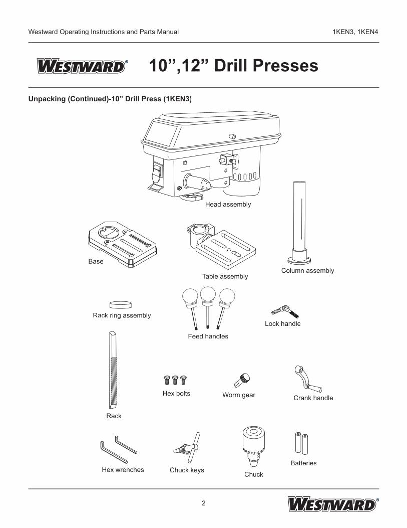
UnpackingAfter unpacking unit, inspect carefully for any damage that may have occurred during transit. Check for loose, missing, or damaged parts. The drill press is shipped partially assembled. Locate and identify the following assemblies and loose parts: head assembly, base, column assembly, rack ring and table assembly. Contents of hardware bag includes: Drill chuck, chuck key, rack, feed handles, worm gear, crank handle, lock handle, hex bolts, 3mm & 4mm hex wrenches and batteries.IMPORTANT: Many unpainted steel surfaces, such as column and table top, have been coated with a protectant. To ensure proper fi t and operation, remove coating. Coating is easily removed with mild solvents, such as mineral spirits, and a soft cloth. Avoid getting solution on paint or any of the rubber or plastic parts. Solvents may deteriorate these fi nishes. Use soap and water on paint,plastic or rubber components. After cleaning, cover all exposed surfaces with a light coating of oil. Paste wax is recommended for table top.
If any part is missing or damaged, do not plug the drill press in until the missing or damaged part is replaced, and assembly is complete. Carefully unpack the drill press and all its parts, and compare against the list below.To protect the drill press from moisture, a protective coating has been applied to the machined surfaces. Remove this coating with a soft cloth moistened with kerosene or WD-40.To avoid fi re or toxic reaction, never use gasoline, naphtha, acetone, lacquer thinner or similar highly volatile solvents to clean the drill press.
WARNING If any part is missing or damaged, do not plug the drill press in until the missing or damaged part is WARNING If any part is missing or damaged, do not plug the drill press in until the missing or damaged part is If any part is missing or damaged, do not plug the drill press in until the missing or damaged part is If any part is missing or damaged, do not plug the drill press in until the missing or damaged part is ! If any part is missing or damaged, do not plug the drill press in until the missing or damaged part is
REX001Printed in China09/06
2
Westward Operating Instructions and Parts Manual 1KEN3, 1KEN4
10”,12” Drill PressesUnpacking (Continued)-10” Drill Press (1KEN3)
Head assembly
Base
Table assemblyColumn assembly
Rack ring assembly
Feed handles
Lock handle
Rack
Worm gear Crank handle
Hex wrenches Chuck keys Chuck
Batteries
Hex bolts
3
Westward Operating Instructions and Parts Manual 1KEN3, 1KEN4
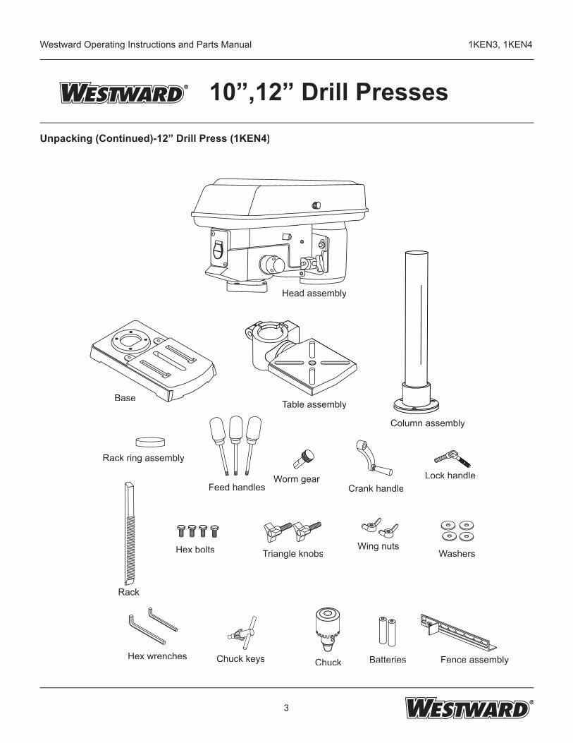
10”,12” Drill PressesUnpacking (Continued)-12” Drill Press (1KEN4)
Head assembly
Table assemblyBase
Column assembly
Lock handleFeed handles
Worm gear
Rack ring assembly
Rack
Hex wrenches Chuck keys Chuck Batteries
Crank handle
Hex bolts
Fence assembly
Triangle knobsWing nuts
Washers
4
Westward Operating Instructions and Parts Manual 1KEN3, 1KEN4
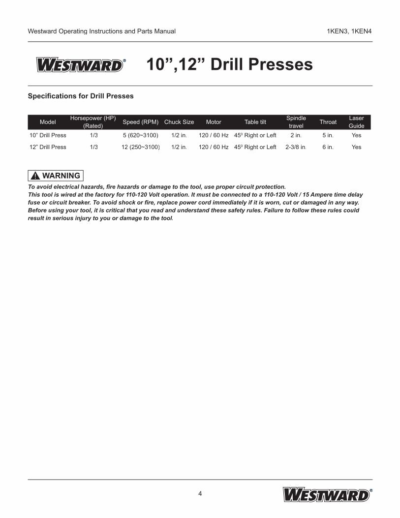
10”,12” Drill PressesSpecifi cations for Drill Presses
WARNING!To avoid electrical hazards, fi re hazards or damage to the tool, use proper circuit protection. This tool is wired at the factory for 110-120 Volt operation. It must be connected to a 110-120 Volt / 15 Ampere time delay fuse or circuit breaker. To avoid shock or fi re, replace power cord immediately if it is worn, cut or damaged in any way.Before using your tool, it is critical that you read and understand these safety rules. Failure to follow these rules could result in serious injury to you or damage to the tool.
Model Horsepower (HP)(Rated) Speed (RPM) Chuck Size Motor Table tilt Spindle
travel Throat Laser Guide
10” Drill Press 1/3 5 (620~3100) 1/2 in. 120 / 60 Hz 450 Right or Left 2 in. 5 in. Yes
12” Drill Press 1/3 12 (250~3100) 1/2 in. 120 / 60 Hz 450 Right or Left 2-3/8 in. 6 in. Yes
5
Westward Operating Instructions and Parts Manual 1KEN3, 1KEN4
10”,12” Drill PressesGeneral Safety Information
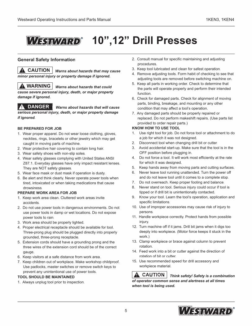
Warns about hazards that may cause minor personal injury or property damage if ignored.
Warns about hazards that could cause severe personal injury, death, or major property damage if ignored.
Warns about hazards that will cause serious personal injury, death, or major property damage if ignored.
BE PREPARED FOR JOB1. Wear proper apparel. Do not wear loose clothing, gloves,
neckties, rings, bracelets or other jewelry which may get caught in moving parts of machine.
2. Wear protective hair covering to contain long hair.3. Wear safety shoes with non-slip soles.4. Wear safety glasses complying with United States ANSI
Z87.1. Everyday glasses have only impact resistant lenses. They are NOT safety glasses.
5. Wear face mask or dust mask if operation is dusty.6. Be alert and think clearly. Never operate power tools when
tired, intoxicated or when taking medications that cause drowsiness.
PREPARE WORK AREA FOR JOB1. Keep work area clean. Cluttered work areas invite
accidents.2. Do not use power tools in dangerous environments. Do not
use power tools in damp or wet locations. Do not expose power tools to rain.
3. Work area should be properly lighted.4. Proper electrical receptacle should be available for tool.
Three-prong plug should be plugged directly into properly grounded, three-prong receptacle.
5. Extension cords should have a grounding prong and the three wires of the extension cord should be of the correct gauge.
6. Keep visitors at a safe distance from work area.7. Keep children out of workplace. Make workshop childproof.
Use padlocks, master switches or remove switch keys to prevent any unintentional use of power tools.
TOOL SHOULD BE MAINTAINED1. Always unplug tool prior to inspection.
WARNING !
CAUTION !
Warns about hazards that will cause Warns about hazards that will cause Warns about hazards that will cause DANGER!
2. Consult manual for specifi c maintaining and adjusting procedures.
3. Keep tool lubricated and clean for safest operation.4. Remove adjusting tools. Form habit of checking to see that
adjusting tools are removed before switching machine on.5. Keep all parts in working order. Check to determine that
the parts will operate properly and perform their intended function.
6. Check for damaged parts. Check for alignment of moving parts, binding, breakage, and mounting or any other condition that may affect a tool’s operation.
7. Any damaged parts should be properly repaired or replaced. Do not perform makeshift repairs. (Use parts list provided to order repair parts.)
KNOW HOW TO USE TOOL1. Use right tool for job. Do not force tool or attachment to do
a job for which it was not designed.2. Disconnect tool when changing drill bit or cutter.3. Avoid accidental start-up. Make sure that the tool is in the
OFF position before plugging in.4. Do not force a tool. It will work most effi ciently at the rate
for which it was designed.5. Keep hands away from moving parts and cutting surfaces.6. Never leave tool running unattended. Turn the power off
and do not leave tool until it comes to a complete stop.7. Do not overreach. Keep proper footing and balance.8. Never stand on tool. Serious injury could occur if tool is
tipped or if drill bit is unintentionally contacted.9. Know your tool. Learn the tool’s operation, application and
specifi c limitations.10. Use of improper accessories may cause risk of injury to
persons.11. Handle workpiece correctly. Protect hands from possible
injury.12. Turn machine off if it jams. Drill bit jams when it digs too
deeply into workpiece. (Motor force keeps it stuck in the work.)
13. Clamp workpiece or brace against column to prevent rotation.
14. Feed work into a bit or cutter against the direction of rotation of bit or cutter.
15. Use recommended speed for drill accessory and workpiece material.
Think safety! Safety is a combination of operator common sense and alertness at all times when tool is being used.
Think safety! Safety is a combination CAUTION Think safety! Safety is a combination CAUTION Think safety! Safety is a combination Think safety! Safety is a combination Think safety! Safety is a combination !
6
Westward Operating Instructions and Parts Manual 1KEN3, 1KEN4
10”,12” Drill PressesAssembly
For your own safety, never connect plug to power source outlet until all assembly steps are complete and you have read and understood the safety and operating instructions.
ON / OFF switch (Figure 1)The ON / OFF switch has a removable, safety switchkey. With the key removed from the switch, unauthorizedand hazardous use by children and others are minimizedas the switch can not be turned on without the key.
1. To turn the drill press “ON”, insert key (2) into the slot of the switch (1). Move the switch upward to the “ON” position.2. To turn the drill press “OFF”, move the switch downward.3. To lock the switch in the OFF position, grasp the sides of the safety switch key, and pull it out.4. With the switch key removed, the switch will not turn the power tool on.5. If the switch key is removed while the drill press is running, it can be turned “OFF” but cannot be restarted without inserting the switch key.
ALWAYS lock the switch “OFF” when the drill press is not in use by removing the safety switch key keep it in a safe place. In the event of a power failure, blown fuse, or tripped circuit breaker, turn the switch “OFF” and remove the key, preventing an accidental startup when power comes on.
Figure 1
The drill press is a heavy power tool and should be lifted with the help of two people OR MORE to safely assemble it.
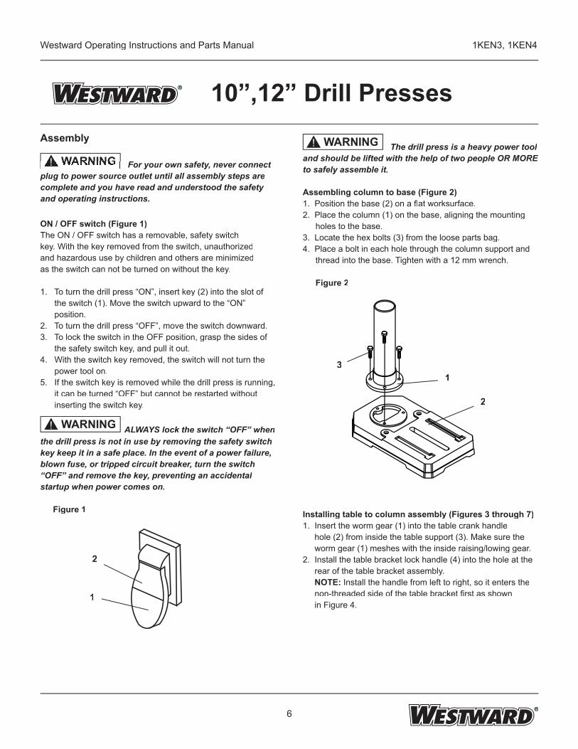
Assembling column to base (Figure 2)1. Position the base (2) on a fl at worksurface.2. Place the column (1) on the base, aligning the mounting
holes to the base.3. Locate the hex bolts (3) from the loose parts bag.4. Place a bolt in each hole through the column support and
thread into the base. Tighten with a 12 mm wrench.
Figure 2
Installing table to column assembly (Figures 3 through 7)1. Insert the worm gear (1) into the table crank handle hole (2) from inside the table support (3). Make sure the worm gear (1) meshes with the inside raising/lowing gear.2. Install the table bracket lock handle (4) into the hole at the rear of the table bracket assembly. NOTE: Install the handle from left to right, so it enters the non-threaded side of the table bracket fi rst as shown in Figure 4.
WARNING For your own safety, never connect WARNING For your own safety, never connect For your own safety, never connect For your own safety, never connect ! For your own safety, never connect
WARNING!
31
2
WARNING!
1
2
7
Westward Operating Instructions and Parts Manual 1KEN3, 1KEN4
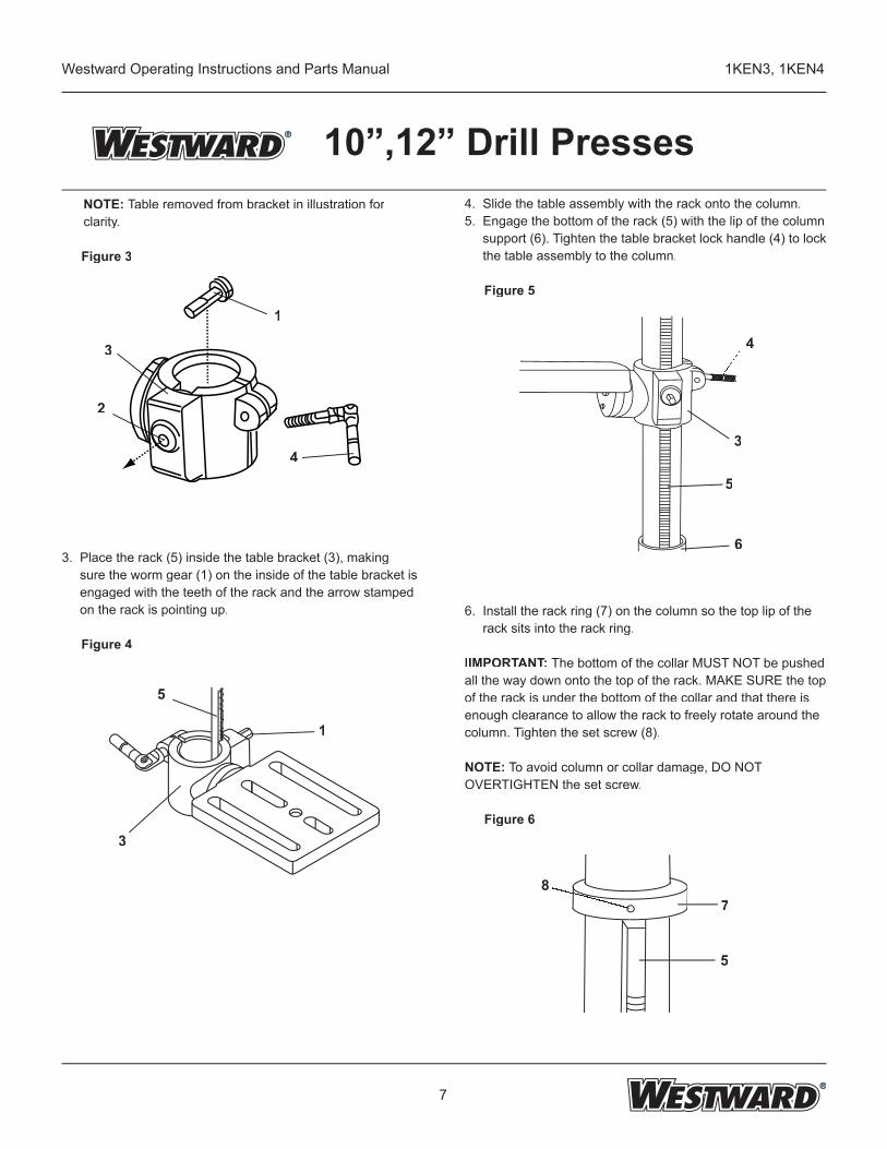
10”,12” Drill Presses NOTE: Table removed from bracket in illustration for clarity.
Figure 3
3. Place the rack (5) inside the table bracket (3), making sure the worm gear (1) on the inside of the table bracket is engaged with the teeth of the rack and the arrow stamped on the rack is pointing up.
Figure 4
4. Slide the table assembly with the rack onto the column.5. Engage the bottom of the rack (5) with the lip of the column support (6). Tighten the table bracket lock handle (4) to lock the table assembly to the column.
Figure 5
6. Install the rack ring (7) on the column so the top lip of the rack sits into the rack ring.
IIMPORTANT: The bottom of the collar MUST NOT be pushed all the way down onto the top of the rack. MAKE SURE the top of the rack is under the bottom of the collar and that there is enough clearance to allow the rack to freely rotate around the column. Tighten the set screw (8). NOTE: To avoid column or collar damage, DO NOTOVERTIGHTEN the set screw.
Figure 6
4
3
5
6
87
5
1
3
2
4
5
3
1
8
Westward Operating Instructions and Parts Manual 1KEN3, 1KEN4
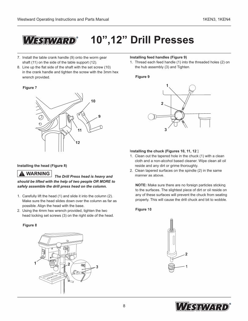
10”,12” Drill Presses7. Install the table crank handle (9) onto the worm gear shaft (11) on the side of the table support (12).8. Line up the fl at side of the shaft with the set screw (10) in the crank handle and tighten the screw with the 3mm hex wrench provided.
Figure 7
Installing the head (Figure 8)
The Drill Press head is heavy and The Drill Press head is heavy and Tshould be lifted with the help of two people OR MORE to safely assemble the drill press head on the column.
1. Carefully lift the head (1) and slide it into the column (2). Make sure the head slides down over the column as far as possible. Align the head with the base.2. Using the 4mm hex wrench provided, tighten the two head locking set screws (3) on the right side of the head.
Figure 8
Installing feed handles (Figure 9)1. Thread each feed handle (1) into the threaded holes (2) on the hub assembly (3) and Tighten.
Figure 9
Installing the chuck (Figures 10, 11, 12 )1. Clean out the tapered hole in the chuck (1) with a clean cloth and a non-alcohol based cleaner. Wipe clean all oil reside and any dirt or grime thoroughly.2. Clean tapered surfaces on the spindle (2) in the same manner as above.
NOTE: Make sure there are no foreign particles sticking to the surfaces. The slightest piece of dirt or oil reside on any of these surfaces will prevent the chuck from seating properly. This will cause the drill chuck and bit to wobble.
Figure 10
1
2
3
2
1
10
9
11
12
1 2 3
WARNING!
9
Westward Operating Instructions and Parts Manual 1KEN3, 1KEN4
10”,12” Drill Presses
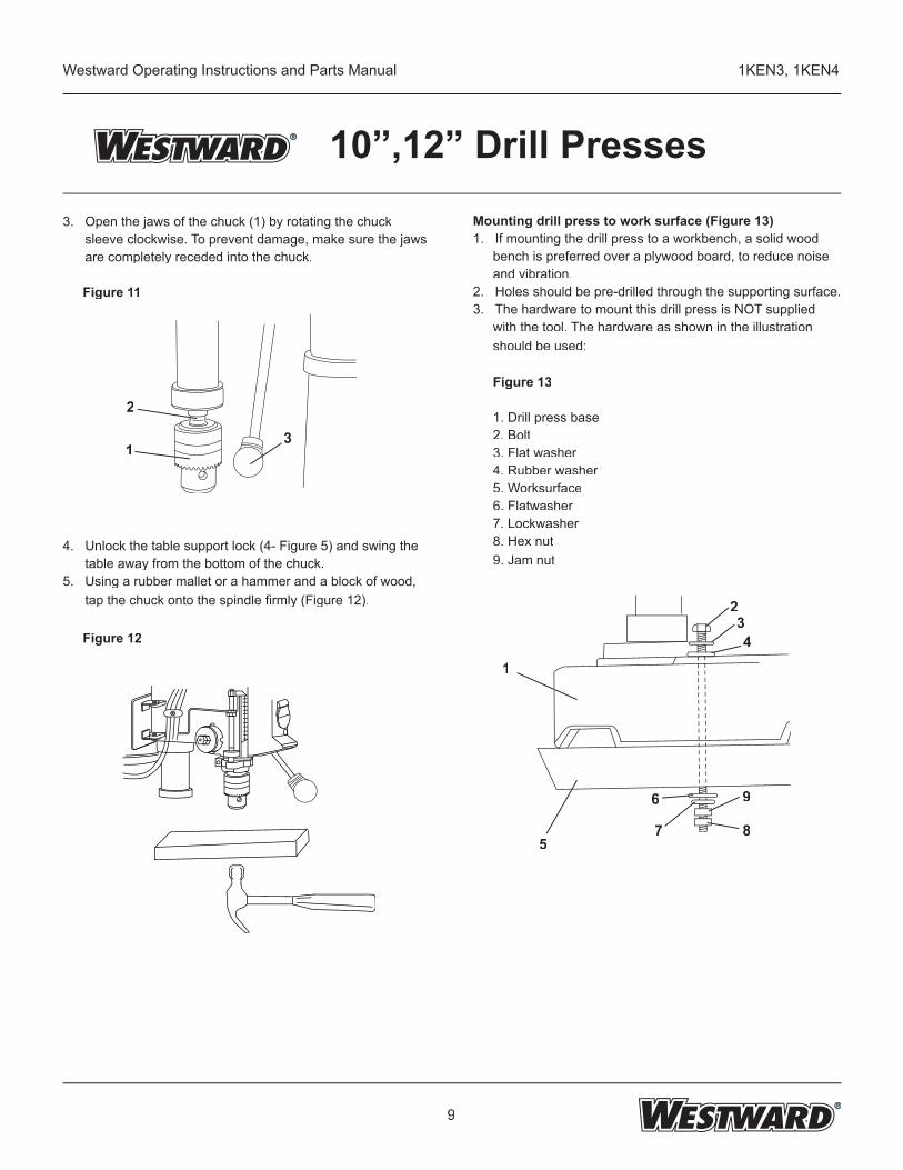
3. Open the jaws of the chuck (1) by rotating the chuck sleeve clockwise. To prevent damage, make sure the jaws are completely receded into the chuck.
Figure 11
4. Unlock the table support lock (4- Figure 5) and swing the table away from the bottom of the chuck.5. Using a rubber mallet or a hammer and a block of wood, tap the chuck onto the spindle fi rmly (Figure 12).
Figure 12
Mounting drill press to work surface (Figure 13)1. If mounting the drill press to a workbench, a solid wood
bench is preferred over a plywood board, to reduce noise and vibration.
2. Holes should be pre-drilled through the supporting surface.3. The hardware to mount this drill press is NOT supplied
with the tool. The hardware as shown in the illustration should be used:
Figure 13
1. Drill press base2. Bolt3. Flat washer4. Rubber washer5. Worksurface6. Flatwasher7. Lockwasher8. Hex nut9. Jam nut
1
5
234
6
7
9
8
2
13
10
Westward Operating Instructions and Parts Manual 1KEN3, 1KEN4
10”,12” Drill Presses
Adjustments instructions
NOTE: All the adjustments for the operation of the drill press have been completed at the factory. Due to normal wear and use, some occasional readjustments may be necessary.
WARNING! To avoid injury from an accidental start, ALWAYS make sure the switch is in the “OFF” position, the switch key is removed, and the plug is not connected to the power source outlet before making belt adjustments.
Squaring table to head (Figure. 15, 16)
NOTE: The table arm and support has a predrilled hole with a locking set screw inserted for locking the table to a predetermined 0° horizontal position. It must be loosened to change the angle of the table.
1. Insert a 1/4”, or larger diameter, precision ground steel rod (1), approximately 3” long, into the chuck (2). Tighten the chuck jaws.
2. Raise table to working height and lock.3. Using the combination square (3), place one edge fl at on
the table, and align the other edge vertically beside the rod (1).
4. (Figure 16) If an adjustment is necessary, loosen the locking set screw (4) with the 3 mm hex key to RELEASE the table from the horizontal position.
5. Loosen the large hex head bevel locking bolt (5).
WARNING! To prevent injury, be sure to hold the table and table arm assembly, so it will not swivel or tilt.
6. Align the square to the rod by rotating the table until the square and rod are in line.
7. Retighten the large hex bolt (5).
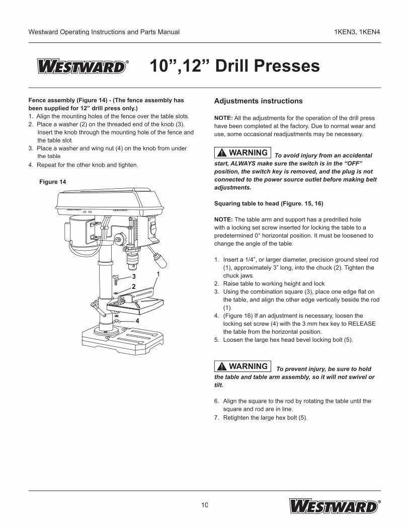
Fence assembly (Figure 14) - (The fence assembly has been supplied for 12” drill press only.)1. Align the mounting holes of the fence over the table slots.2. Place a washer (2) on the threaded end of the knob (3).
Insert the knob through the mounting hole of the fence and the table slot.
3. Place a washer and wing nut (4) on the knob from under the table.
4. Repeat for the other knob and tighten.
Figure 14
132
4
11
Westward Operating Instructions and Parts Manual 1KEN3, 1KEN4
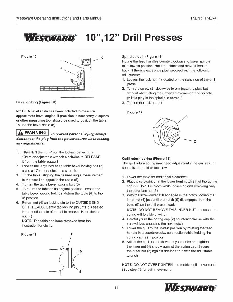
10”,12” Drill PressesFigure 15
Bevel drilling (Figure 16)
NOTE: A bevel scale has been included to measure approximate bevel angles. If precision is necessary, a square or other measuring tool should be used to position the table. To use the bevel scale (6):
To prevent personal injury, always disconnect the plug from the power source when making any adjustments.
1. TIGHTEN the nut (4) on the locking pin using a 10mm or adjustable wrench clockwise to RELEASE it from the table support.2. Loosen the large hex head table bevel locking bolt (5) using a 17mm or adjustable wrench.3. Tilt the table, aligning the desired angle measurement to the zero line opposite the scale (6).4. Tighten the table bevel locking bolt (5).5. To return the table to its original position, loosen the table bevel locking bolt (5). Return the table (6) to the 0° position.6. Return nut (4) on locking pin to the OUTSIDE END OF THREADS. Gently tap locking pin until it is seated in the mating hole of the table bracket. Hand tighten nut (4). NOTE: The table has been removed form the illustration for clarity.
Figure 16
Spindle / quill (Figure 17)Rotate the feed handles counterclockwise to lower spindle to its lowest position. Hold the chuck and move it front to back. If there is excessive play, proceed with the following adjustments:1. Loosen the lock nut (1) located on the right side of the drill
press.2. Turn the screw (2) clockwise to eliminate the play, but
without obstructing the upward movement of the spindle. (A little play in the spindle is normal.)3. Tighten the lock nut (1).
Figure 17
Quill return spring (Figure 18)The quill return spring may need adjustment if the quill return speed is too rapid or too slow.
1. Lower the table for additional clearance.2. Place a screwdriver in the lower front notch (1) of the spring cap (2). Hold it in place while loosening and removing only the outer jam nut (3).3. With the screwdriver still engaged in the notch, loosen the inner nut (4) just until the notch (5) disengages from the boss (6) on the drill press head. NOTE: DO NOT REMOVE THIS INNER NUT, because the spring will forcibly unwind.4. Carefully turn the spring cap (2) counterclockwise with the screwdriver, engaging the next notch.5. Lower the quill to the lowest position by rotating the feed handle in a counterclockwise direction while holding the spring cap (2) in position.6. Adjust the quill up and down as you desire and tighten the inner nut (4) snugly against the spring cap. Secure the outer nut (3) against the inner nut with the adjustable wrench.
NOTE: DO NOT OVERTIGHTEN and restrict quill movement.(See step #5 for quill movement)
1
2
WARNING!
3
1 2
6
5
4
12
Westward Operating Instructions and Parts Manual 1KEN3, 1KEN4
10”,12” Drill Presses
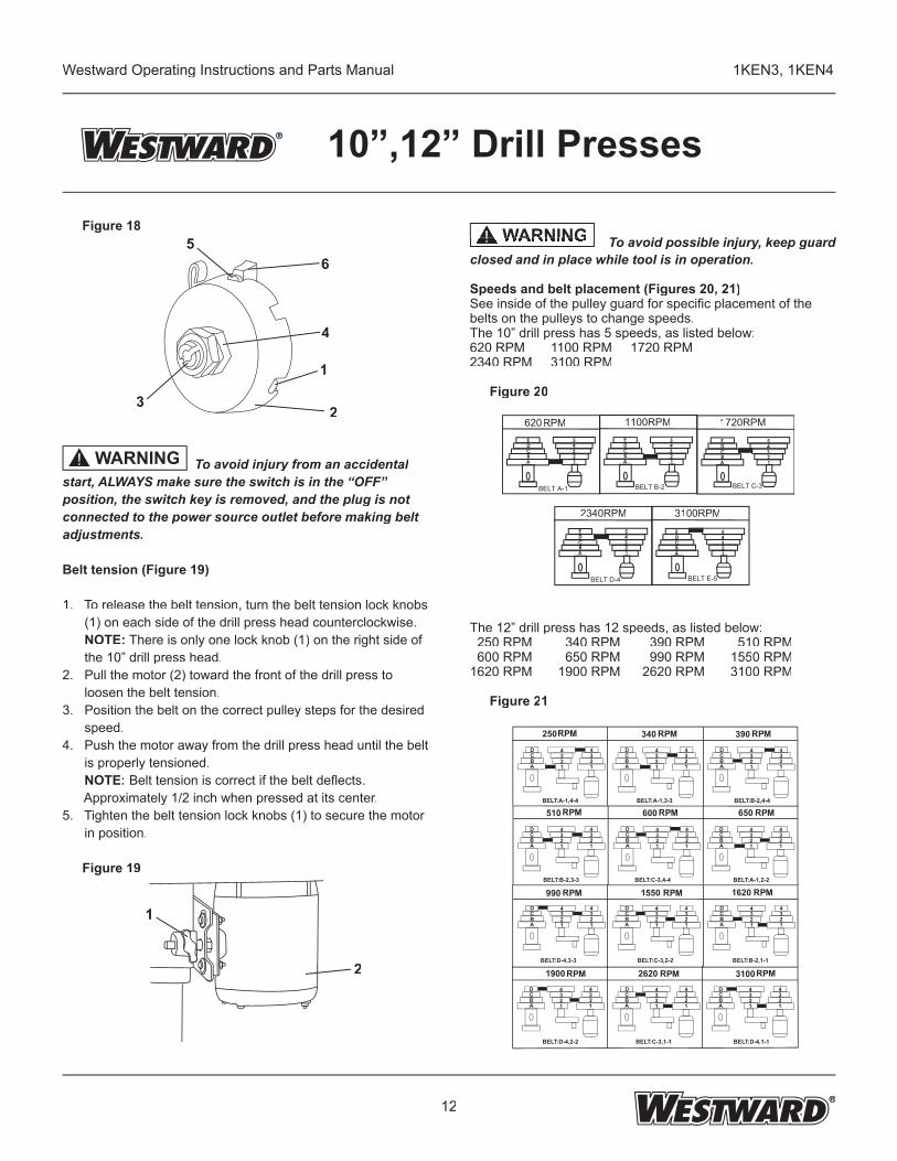
To avoid possible injury, keep guard closed and in place while tool is in operation.
Speeds and belt placement (Figures 20, 21)See inside of the pulley guard for specifi c placement of the belts on the pulleys to change speeds.The 10” drill press has 5 speeds, as listed below:620 RPM 1100 RPM 1720 RPM 2340 RPM 3100 RPM
Figure 20
The 12” drill press has 12 speeds, as listed below: 250 RPM 340 RPM 390 RPM 510 RPM 600 RPM 650 RPM 990 RPM 1550 RPM1620 RPM 1900 RPM 2620 RPM 3100 RPM
Figure 21
Figure 18
To avoid injury from an accidental start, ALWAYS make sure the switch is in the “OFF” position, the switch key is removed, and the plug is not connected to the power source outlet before making belt adjustments.
Belt tension (Figure 19)
1. To release the belt tension, turn the belt tension lock knobs (1) on each side of the drill press head counterclockwise. NOTE: There is only one lock knob (1) on the right side of the 10” drill press head.2. Pull the motor (2) toward the front of the drill press to loosen the belt tension.3. Position the belt on the correct pulley steps for the desired speed.4. Push the motor away from the drill press head until the belt is properly tensioned. NOTE: Belt tension is correct if the belt defl ects. Approximately 1/2 inch when pressed at its center.5. Tighten the belt tension lock knobs (1) to secure the motor in position.
Figure 19
5
3
6
4
1
2
1
2
WARNING!
WARNING To avoid possible injury, keep guard WARNING To avoid possible injury, keep guard To avoid possible injury, keep guard To avoid possible injury, keep guard ! To avoid possible injury, keep guard
BELT A-1 BELT B-2 BELT C-3
BELT D-4 BELT E-5
RPM 1100RPM 1720RPM
2340RPM 3100RPM
620
ABCDE
ABCDE
12345
12345
ABCDE
12345
ABCDE
12345
ABCDE
12345
250RP M 340 390
990 5501 6201
510 600 650
9001 6202 1003
RP M RP M
RP M RP M RP M
RP M RP M RP M
RP M RP M RP M
13
Westward Operating Instructions and Parts Manual 1KEN3, 1KEN4
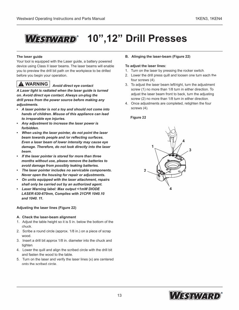
10”,12” Drill PressesB. Alinging the laser-beam (Figure 22)
To adjust the laser lines:1. Turn on the laser by pressing the rocker switch.2. Lower the drill press quill and loosen one turn each the four screws (4).3. To adjust the laser beam left/right, turn the adjustment screw (1) no more than 1/8 turn in either direction. To adjust the laser beam front to back, turn the adjusting screw (2) no more than 1/8 turn in either direction.4. Once adjustments are completed, retighten the four screws (4).
Figure 22
The laser guideYour tool is equipped with the Laser guide, a battery powered device using Class II laser beams. The laser beams will enable you to preview the drill bit path on the workpiece to be drilledbefore you begin your operation.
Avoid direct eye contactA Laser light is radiated when the laser guide is turnedon. Avoid direct eye contact. Always un-plug thedrill press from the power source before making anyadjustments.• A laser pointer is not a toy and should not come into hands of children. Misuse of this appliance can lead to irreparable eye injuries.• Any adjustment to increase the laser power is forbidden.• When using the laser pointer, do not point the laser beam towards people and /or refl ecting surfaces. Even a laser beam of lower intensity may cause eye damage. Therefore, do not look directly into the laser beam.• If the laser pointer is stored for more than three months without use, please remove the batteries to avoid damage from possibly leaking batteries.• The laser pointer includes no servicable components. Never open the housing for repair or adjustments.• On units equipped with the laser attachment, repairs shall only be carried out by an authorized agent.• Laser Warning label: Max output <1mW DIODE LASER:630-670nm, Complies with 21CFR 1040.10 and 1040. 11.
Adjusting the laser lines (Figure 22) A. Check the laser-beam alignment1. Adjust the table height so it is 5 in. below the bottom of the
chuck.2. Scribe a round circle (approx. 1/8 in.) on a piece of scrap
wood.3. Insert a drill bit approx 1/8 in. diameter into the chuck and
tighten.4. Lower the quill and align the scribed circle with the drill bit
and fasten the wood to the table.5. Turn on the laser and verify the laser lines (x) are centered
onto the scribed circle.
2
4
41
3
WARNING!
14
Westward Operating Instructions and Parts Manual 1KEN3, 1KEN4
10”,12” Drill PressesOperation
Basic drill press operation
Installing drill bit in chuck (Figure 23)1. With the switch “OFF” and the switch key removed, open the chuck jaws (1) using the chuck key (2). Turn the chuck key counterclockwise to open the chuck jaws (1).2. Insert the drill bit (3) into the chuck far enough to obtain maximum gripping by the jaws, but not far enough to touch the spiral grooves (fl utes) of the drill bit when the jaws are tightened.3. Make sure that the drill is centered in the chuck.4. Turn the chuck key clockwise to tighten the jaws.
To avoid injury or accident by the chuck key ejecting forcibly from the chuck when the power is turned “ON”, use only the self-ejecting chuck key supplied with this drill press. ALWAYS recheck and remove the chuck key before turning the power “ON”.
Figure 23
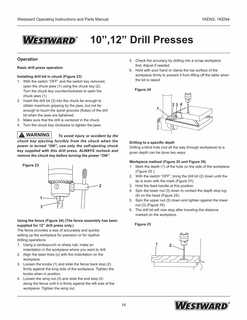
Using the fence (Figure 24) (The fence assembly has been supplied for 12” drill press only.)The fence provides a way of accurately and quicklysetting up the workpiece for precision or for repitivedrilling operations.1. Using a centerpunch or sharp nail, make an indentation in the workpiece where you want to drill.2. Align the laser lines (x) with the indentation on the workpiece.3. Loosen the knobs (1) and slide the fence back stop (2) fi rmly against the long side of the workpiece. Tighten the knobs when in position.4. Loosen the wing nut (3) and slide the end stop (4) along the fence until it is fi rmly against the left side of the workpiece. Tighten the wing nut.
5. Check the accuracy by drilling into a scrap workpiece fi rst. Adjust if needed.6. Hold with your hand or clamp the top surface of the workpiece fi rmly to prevent it from lifting off the table when the bit is raised.
Figure 24
Drilling to a specifi c depthDrilling a blind hole (not all the way through workpiece) to a given depth can be done two ways:
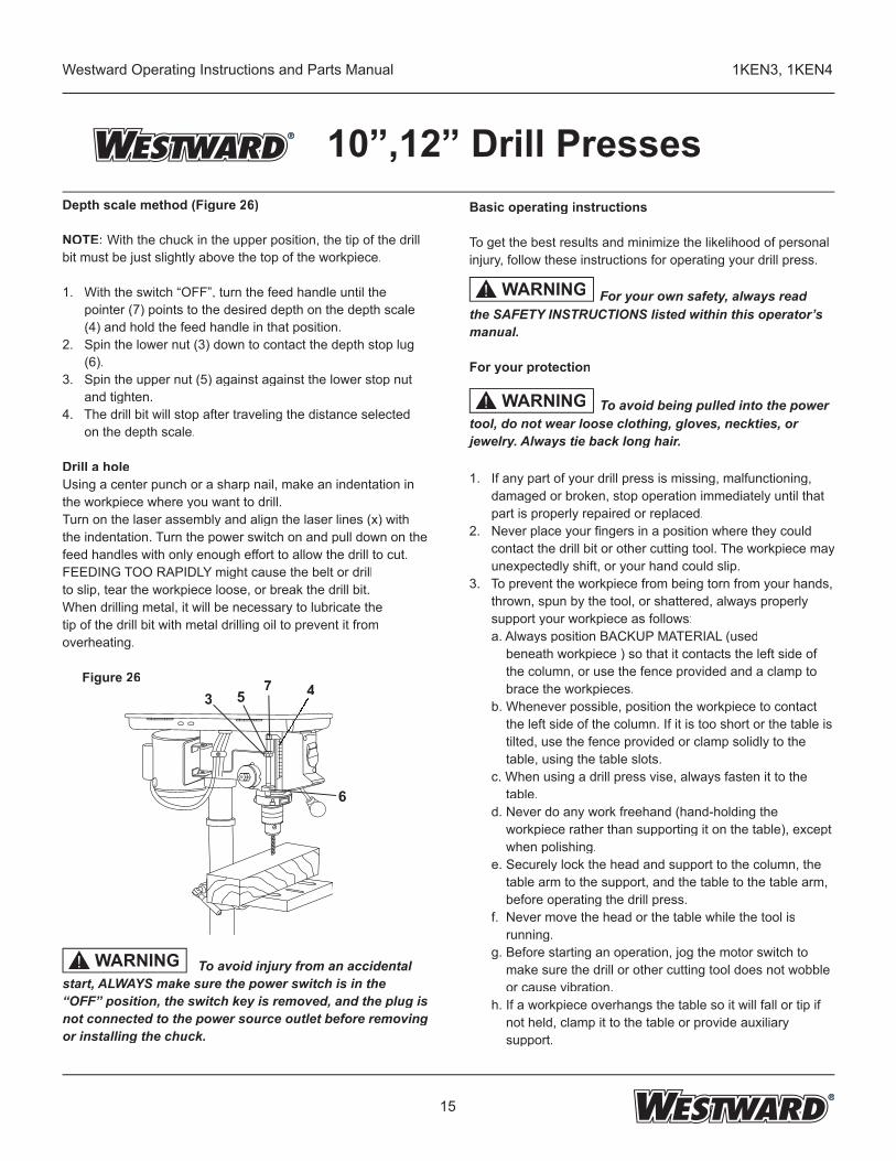
Workpiece method (Figure 25 and Figure 26)1. Mark the depth (1) of the hole on the side of the workpiece (Figure 25 ).2. With the switch “OFF”, bring the drill bit (2) down until the tip is even with the mark (Figure 25).3. Hold the feed handle at this position.4. Spin the lower nut (3) down to contact the depth stop lug (6) on the head (Figure 26).5. Spin the upper nut (5) down and tighten against the lower nut (3) (Figure 26).6. The drill bit will now stop after traveling the distance marked on the workpiece.
Figure 25
WARNING !
1
3
2
12 33 44
21
15
Westward Operating Instructions and Parts Manual 1KEN3, 1KEN4
10”,12” Drill PressesDepth scale method (Figure 26)
NOTE: With the chuck in the upper position, the tip of the drill bit must be just slightly above the top of the workpiece.
1. With the switch “OFF”, turn the feed handle until the pointer (7) points to the desired depth on the depth scale (4) and hold the feed handle in that position.2. Spin the lower nut (3) down to contact the depth stop lug (6).3. Spin the upper nut (5) against against the lower stop nut and tighten.4. The drill bit will stop after traveling the distance selected on the depth scale.
Drill a holeUsing a center punch or a sharp nail, make an indentation in the workpiece where you want to drill.Turn on the laser assembly and align the laser lines (x) with the indentation. Turn the power switch on and pull down on the feed handles with only enough effort to allow the drill to cut.FEEDING TOO RAPIDLY might cause the belt or drillto slip, tear the workpiece loose, or break the drill bit.When drilling metal, it will be necessary to lubricate thetip of the drill bit with metal drilling oil to prevent it fromoverheating.
Figure 26
To avoid injury from an accidental start, ALWAYS make sure the power switch is in the “OFF” position, the switch key is removed, and the plug is not connected to the power source outlet before removing or installing the chuck.
Basic operating instructions
To get the best results and minimize the likelihood of personal injury, follow these instructions for operating your drill press.
For your own safety, always read the SAFETY INSTRUCTIONS listed within this operator’s manual.
For your protection
To avoid being pulled into the power tool, do not wear loose clothing, gloves, neckties, or jewelry. Always tie back long hair.
1. If any part of your drill press is missing, malfunctioning, damaged or broken, stop operation immediately until that part is properly repaired or replaced.2. Never place your fi ngers in a position where they could contact the drill bit or other cutting tool. The workpiece may unexpectedly shift, or your hand could slip.3. To prevent the workpiece from being torn from your hands, thrown, spun by the tool, or shattered, always properly support your workpiece as follows: a. Always position BACKUP MATERIAL (used beneath workpiece ) so that it contacts the left side of the column, or use the fence provided and a clamp to brace the workpieces. b. Whenever possible, position the workpiece to contact the left side of the column. If it is too short or the table is tilted, use the fence provided or clamp solidly to the table, using the table slots. c. When using a drill press vise, always fasten it to the table. d. Never do any work freehand (hand-holding the workpiece rather than supporting it on the table), except when polishing. e. Securely lock the head and support to the column, the table arm to the support, and the table to the table arm, before operating the drill press. f. Never move the head or the table while the tool is running. g. Before starting an operation, jog the motor switch to make sure the drill or other cutting tool does not wobble or cause vibration. h. If a workpiece overhangs the table so it will fall or tip if not held, clamp it to the table or provide auxiliary support.
3 57 4
6
WARNING!
WARNING!
WARNING!
16
Westward Operating Instructions and Parts Manual 1KEN3, 1KEN4
10”,12” Drill Presses i. Use fi xtures for unusual operations to adequately hold, guide, and position workpiece. j. Use the SPINDLE SPEED recommended for the specifi c operation and workpiece material. Check the panel on the inside pulley cover or the chart below for drilling speed information. For accessories, refer to the instructions provided with each accessory.4. Never climb on the drill press table, it could break or pull the entire drill press down on you.5. Turn the power switch “OFF”, and put away the switch key when leaving the drill press.6. To avoid injury from thrown work or tool contact, do not perform layout, assembly, or setup work on the table while the cutting tool is rotating.
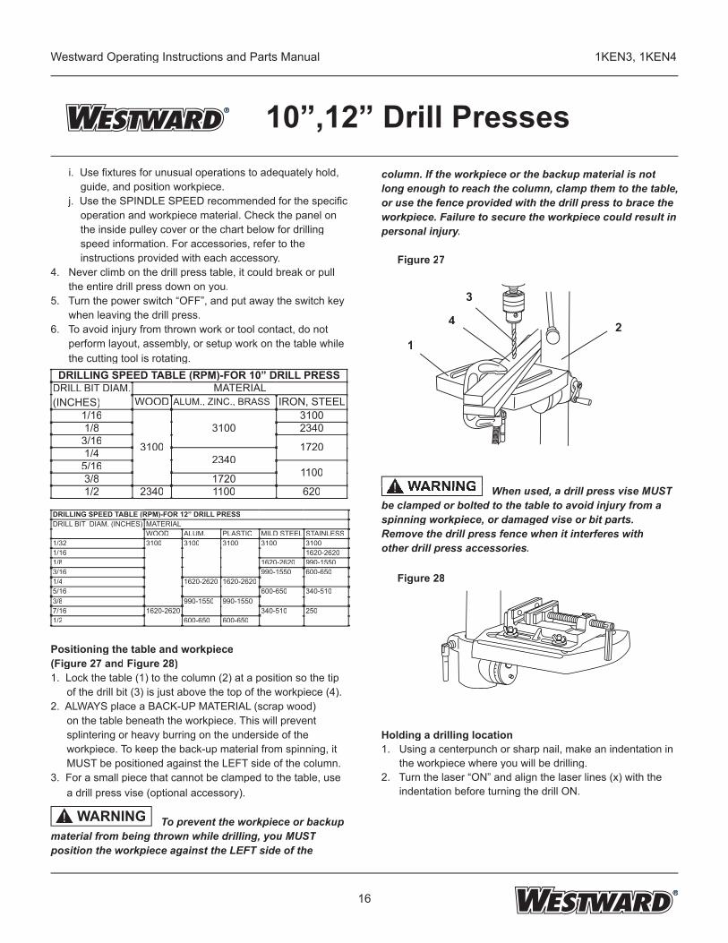
Positioning the table and workpiece (Figure 27 and Figure 28)1. Lock the table (1) to the column (2) at a position so the tip
of the drill bit (3) is just above the top of the workpiece (4).2. ALWAYS place a BACK-UP MATERIAL (scrap wood)
on the table beneath the workpiece. This will prevent splintering or heavy burring on the underside of the workpiece. To keep the back-up material from spinning, it MUST be positioned against the LEFT side of the column.
3. For a small piece that cannot be clamped to the table, use a drill press vise (optional accessory).
To prevent the workpiece or backup material from being thrown while drilling, you MUST position the workpiece against the LEFT side of the
column. If the workpiece or the backup material is not long enough to reach the column, clamp them to the table, or use the fence provided with the drill press to brace the workpiece. Failure to secure the workpiece could result in personal injury.
Figure 27
When used, a drill press vise MUST be clamped or bolted to the table to avoid injury from a spinning workpiece, or damaged vise or bit parts.Remove the drill press fence when it interferes withother drill press accessories.
Figure 28
Holding a drilling location1. Using a centerpunch or sharp nail, make an indentation in the workpiece where you will be drilling.2. Turn the laser “ON” and align the laser lines (x) with the indentation before turning the drill ON.
DRILLING SPEED TABLE (RPM)-FOR 10” DRILL PRESSDRILL BIT DIAM. (INCHES)
MATERIALWOOD ALUM., ZINC., BRASS IRON, STEEL
1/16
3100
31003100
1/8 23403/16 17201/4 23405/16 11003/8 17201/2 2340 1100 620
WARNING!
WARNING When used, WARNING When used, When used, When used, ! When used,
DRILLING SPEED TABLE (RPM)-FOR 12” DRILL PRESSDRILL BIT DIAM. (INCHES) MATERIAL
WOOD ALUM. PLASTIC MILD STEEL STAINLESS1/32 3100 3100 3100 3100 31001/16 1620-26201/8 1620-2620 990-15503/16 990-1550 600-6501/4 1620-2620 1620-26205/16 600-650 340-5103/8 990-1550 990-15507/16 1620-2620 340-510 2501/2 600-650 600-650
2
3
4
1
17
Westward Operating Instructions and Parts Manual 1KEN3, 1KEN4
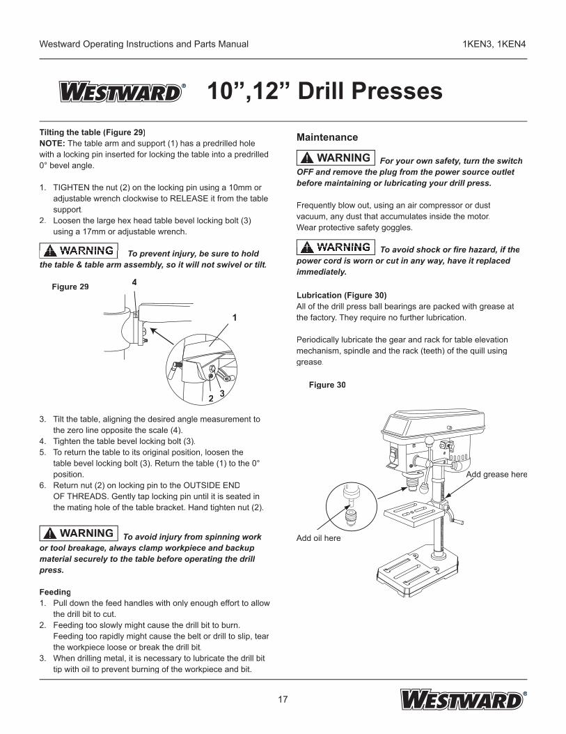
10”,12” Drill PressesTilting the table (Figure 29)NOTE: The table arm and support (1) has a predrilled hole with a locking pin inserted for locking the table into a predrilled 0° bevel angle.
1. TIGHTEN the nut (2) on the locking pin using a 10mm or adjustable wrench clockwise to RELEASE it from the table support.2. Loosen the large hex head table bevel locking bolt (3) using a 17mm or adjustable wrench. To prevent injury, be sure to holdthe table & table arm assembly, so it will not swivel or tilt.
Figure 29
3. Tilt the table, aligning the desired angle measurement to the zero line opposite the scale (4).4. Tighten the table bevel locking bolt (3).5. To return the table to its original position, loosen the table bevel locking bolt (3). Return the table (1) to the 0° position.6. Return nut (2) on locking pin to the OUTSIDE END OF THREADS. Gently tap locking pin until it is seated in the mating hole of the table bracket. Hand tighten nut (2).
To avoid injury from spinning work or tool breakage, always clamp workpiece and backup material securely to the table before operating the drill press.
Feeding1. Pull down the feed handles with only enough effort to allow the drill bit to cut.2. Feeding too slowly might cause the drill bit to burn. Feeding too rapidly might cause the belt or drill to slip, tear the workpiece loose or break the drill bit.3. When drilling metal, it is necessary to lubricate the drill bit tip with oil to prevent burning of the workpiece and bit.
WARNING To prevent injury, be sure to holdWARNING To prevent injury, be sure to hold
To prevent injury, be sure to hold To prevent injury, be sure to hold! To prevent injury, be sure to hold
Maintenance For your own safety, turn the switch OFF and remove the plug from the power source outlet before maintaining or lubricating your drill press.
Frequently blow out, using an air compressor or dustvacuum, any dust that accumulates inside the motor.Wear protective safety goggles.
To avoid shock or fi re hazard, if the power cord is worn or cut in any way, have it replaced immediately.
Lubrication (Figure 30)All of the drill press ball bearings are packed with grease at the factory. They require no further lubrication.
Periodically lubricate the gear and rack for table elevationmechanism, spindle and the rack (teeth) of the quill using grease.
Figure 30
WARNING
!
WARNING To avoid shock or fi re hazard, if the WARNING To avoid shock or fi re hazard, if the To avoid shock or fi re hazard, if the To avoid shock or fi re hazard, if the ! To avoid shock or fi re hazard, if the
WARNING
!
1
332
4
Add grease hereAdd grease here
Add oil here
18
Westward Operating Instructions and Parts Manual 1KEN3, 1KEN4
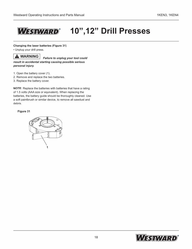
10”,12” Drill PressesChanging the laser batteries (Figure 31)• Unplug your drill press.
Failure to unplug your tool could result in accidental starting causing possible serious personal injury.
1. Open the battery cover (1).2. Remove and replace the two batteries.3. Replace the battery cover.
NOTE: Replace the batteries with batteries that have a rating of 1.5 volts (AAA size or equivalent). When replacing the batteries, the battery guide should be thoroughly cleaned. Use a soft paintbrush or similar device, to remove all sawdust and debris.
Figure 31
1
WARNING!
19
Westward Operating Instructions and Parts Manual 1KEN3, 1KEN4
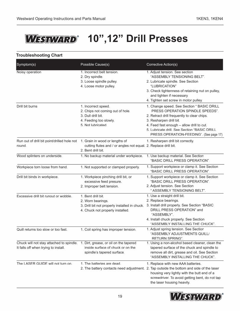
10”,12” Drill PressesTroubleshooting Chart
Symptom(s) Possible Cause(s) Corrective Action(s)
Noisy operation 1. Incorrect belt tension.2. Dry spindle.3. Loose spindle pulley.4. Loose motor pulley.
1. Adjust tension. See section “ASSEMBLY TENSIONING BELT”.2. Lubricate spindle. See Section “LUBRICATION”.
3. Check tightenness of retaining nut on pulley, and tighten if necessary.4. Tighten set screw in motor pulley.
Drill bit burns 1. Incorrect speed.2. Chips not coming out of hole.3. Dull drill bit.4. Feeding too slowly.5. Not lubricated.
1. Change speed. See Section “ BASIC DRILL PRESS OPERATION SPINDLE SPEEDS”.2. Retract drill frequently to clear chips.3. Resharpen drill bit.4. Feed fast enough – allow drill to cut.5. Lubricate drill. See Section “BASIC DRILL PRESS OPERATION-FEEDING”. (See page 17)
Run out of drill bit point/drilled hole not round.
1. Grain in wood or lengths of cutting fl utes and / or angles not equal.2. Bent drill bit.
1. Resharpen drill bit correctly.2. Replace drill bit.
Wood splinters on underside. 1. No backup material under workpiece. 1. Use backup material. See Section “BASIC DRILL PRESS OPERATION”.
Workpiece torn loose from hand. 1. Not supported or clamped properly. 1. Support workpiece or clamp it. See Section “BASIC DRILL PRESS OPERATION”.
Drill bit binds in workpiece. 1. Workpiece pinching drill bit, or excessive feed presure.2. Improper belt tension.
1. Support workpiece or clamp it. See Section “BASIC DRILL PRESS OPERATION”.2. Adjust tension. See Section “ ASSEMBLY TENSIONING BELT”.
Excessive drill bit runout or wobble. 1. Bent drill bit.2. Worn bearings.3. Drill bit not properly installed in chuck.4. Chuck not properly installed.
1. Use a straight drill bit.2. Replace bearings.3. Install drill properly. See Section “BASIC DRILL PRESS OPERATION” and “ASSEMBLY”.4. Install chuck properly. See Section “ASSEMBLY INSTALLING THE CHUCK”.
Quill returns too slow or too fast. 1. Coil spring has improper tension. 1. Adjust spring tension. See Section “ASSEMBLY ADJUSTMENTS QUILL/
RETURN SPRING”.Chuck will not stay attached to spindle. It falls off when trying to install.
1. Dirt, grease, or oil on the tapered inside surface of chuck or on the spindle’s tapered surface.
1. Using a non-alcohol based cleaner, clean the tapered surface of the chuck and spindle to remove all dirt, grease and oil. See Section “ASSEMBLY INSTALLING THE CHUCK”.
The LASER GUIDE will not turn on. 1. The batteries are dead.2. The battery contacts need adjustment.
1. Replace with new AAA batteries.2. Tap outside the bottom and side of the laser housing very lightly with the butt end of a screwdriver. To avoid getting bent, do not tap the laser housing heavily.
20
Westward Operating Instructions and Parts Manual 1KEN3, 1KEN4
10”,12” Drill Presses
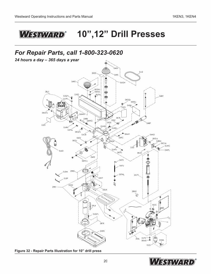
For Repair Parts, call 1-800-323-062024 hours a day – 365 days a year
Figure 32 - Repair Parts Illustration for 10” drill press
2BJ1
0KMY4
2JZX
0L6D
0J3M
0J3P
29R0
0X52
05TW 2A7V
28N2
04VT
29L4
0JQ73
2B7K
2ARX
0J720KMS
0J2J
05UX
2
0J4F80JP44
0KQY2
0KDJ06SV
0JCB
04WN
048K04WG 0J8F4
0VND
0KMY
049C
048P
04AD
0KDJ204BM
0LWC0KC62
0JQ720J7F2
049Z
0KDH304A530K7K4
0UGH
04XV
049S0JJZ
0KSQ20K9X4
0V86
0K7K
04Q4
05SZ
0JXE3
0X55
2K00
2JZV
048Y
0499
0JAF20KFF2
0KPC2
047U
047X
2JZZ
0KUX
2JXD
29R1
0LSC
Z05L 0V8A
0WPL
21
Westward Operating Instructions and Parts Manual 1KEN3, 1KEN4
10”,12” Drill Presses
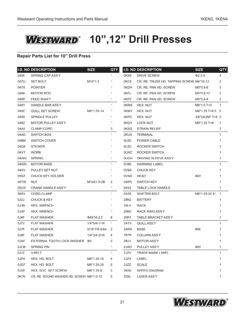
I.D. NO DESCRIPTION SIZE QTY I.D. NO DESCRIPTION SIZE QTY0499 SPRING CAP ASS’Y 1 0K9X DRIVE SCREW Φ2.3-5 4
047U SET BOLT M10*1.5 1 0KC6 CR. RE. TRUSS HD. TAPPING SCREW M4*16-12 2
047X POINTER 1 0KDH CR. RE. PAN HD. SCREW M5*0.8-8 3
048K MOTOR ROD 1 0KDJ CR. RE. PAN HD. SCREW M5*0.8-12 3
048P FEED SHAFT 1 0KFF CR. RE. PAN HD. SCREW M5*0.8-8 2
048Y HANDLE BAR ASS’Y 1 0KMS HEX. NUT M6*1.0 T=5 1
049C QUILL SET SCREW M8*1.25-14 1 0KMY HEX. NUT M8*1.25 T=6.5 5
049S SPINDLE PULLEY 1 0KPC HEX. NUT 3/8*24UNF T=8 2
049Z MOTOR PULLEY ASS’Y 1 0KQY LOCK NUT M8*1.25 T=8 2
04A5 CLAMP-CORD 3 0KSQ STRAIN RELIEF 2
04AD SWITCH BOX 1 0KUX TERMINAL 1
04BM SWITCH COVER 1 0L6D POWER CABLE 1
04Q4 STICKER 1 0LSC ROCKER SWITCH 1
04VT WORM 1 0LWC ROCKER SWITCH 1
04WG SPRING 1 0UGH DRIVING SLEEVE ASS’Y 1
04WN MOTOR BASE 1 0V86 WARNING LABEL 1
04XV PULLEY SET NUT 1 0V8A CHUCK KEY 1
05SZ CHUCK KEY HOLDER 1 0VND HEAD #AY 1
05TW NUT M10X1.5-2B 2 0WPL SWITCH KEY 1
05UX CRANK HANDLE ASS’Y 1 0X52 TABLE LOCK HANDLE 1
06SV CORD-CLAMP 1 0X55 SHIFTER BOLT M8*1.25-20 91 1
0J2J CHUCK & KEY 1 28N2 BATTERY 1
0J3M HEX. WRENCH 1 29L4 RACK 1
0J3P HEX. WRENCH 1 29R0 RACK RING ASS’Y 1
0J4F FLAT WASHER Φ8X16-2.5 8 29R1 TABLE BRACKET ASS’Y 1
0J72 FLAT WASHER 1/4*5/8-1/16 1 2A7V QUILL ASS’Y 1
0J7F FLAT WASHER 5/16*7/8-5/64 2 2ARX BASE #06 1
0J8F FLAT WASHER 1/4*3/4-3/16 4 2B7K COLUMN ASS’Y 1
0JAF EXTERNAL TOOTH LOCK WASHER Φ5 2 2BJ1 MOTOR ASS’Y 1
0JCB SPRING PIN 1 2JXD PULLEY ASS’Y #AY 1
0JJZ V-BELT 1 2JZV TRADE-MARK LABEL 1
0JP4 HEX. HD. BOLT M8*1.25-16 4 2JZX LABEL 1
0JQ7 HEX. HD. BOLT M8*1.25-25 5 2JZZ SCALE 1
0JXE HEX. SOC. SET SCREW M8*1.25-8 3 2K00 SPEED DIAGRAM 1
0K7K CR. RE. ROUND WASHER HD. SCREW M6*1.0-12 5 Z05L LASER ASS’Y 1
Repair Parts List for 10” Drill Press
22
Westward Operating Instructions and Parts Manual 1KEN3, 1KEN4
10”,12” Drill Presses
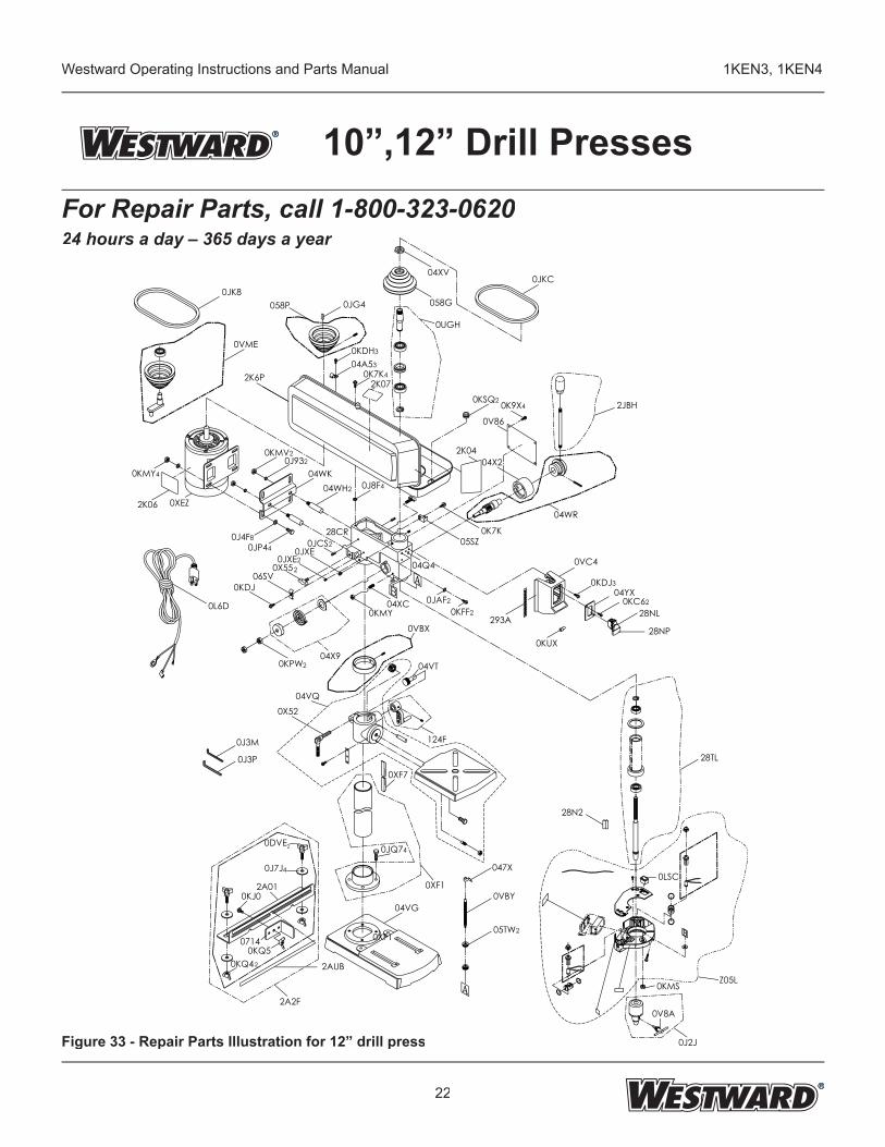
Figure 33 - Repair Parts Illustration for 12” drill press
For Repair Parts, call 1-800-323-062024 hours a day – 365 days a year
0L6D
0KMY4
0JK8
0VME
058P 0JG4
0KDH304A53
0K7K4
0JAF20KFF20KMY
04XC
04Q4
05SZ0J4F80JP44
0KDJ
0KMV20J932
0J8F404WH204WK
06SV
0JXE20JXE
0JCS228CR
2K6P2K07
0X552
2K06 0XEZ
0UGH
058G
04XV
0KSQ20K9X4
0VC4
0KDJ304YX0KC62
0K7K
0KUX
0JKC
0V86
2K0404X2
04WR
28NL
2JBH
293A
28N2
0J2J
0J3M
0J3P
2A2F
0XF1
0JQ74
0XF7
04X9
04VQ
047X
0VBY
05TW2
0KPW2
0X52
0VBX
04VT
124F
28TL
0KMS
04VG
0XF1
0DVE
0J7J4
2A010KJ0
07140KQ5
0KQ42 2AUB
28NP
0LSC
0V8A
Z05L
2
23
Westward Operating Instructions and Parts Manual 1KEN3, 1KEN4
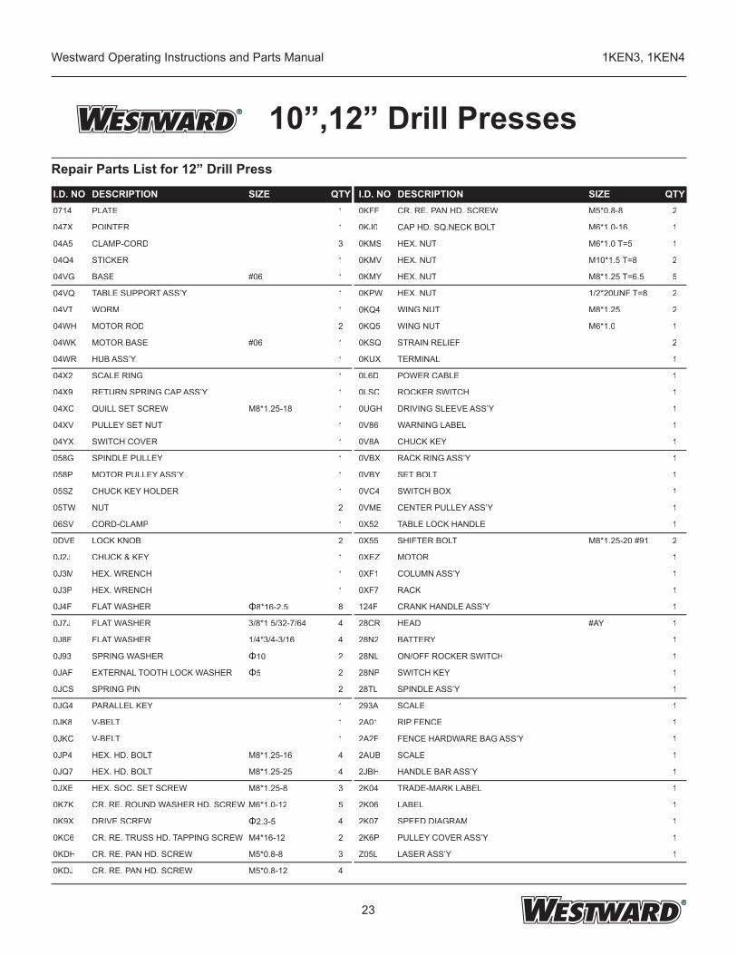
10”,12” Drill PressesRepair Parts List for 12” Drill Press
I.D. NO DESCRIPTION SIZE QTY I.D. NO DESCRIPTION SIZE QTY0714 PLATE 1 0KFF CR. RE. PAN HD. SCREW M5*0.8-8 2
047X POINTER 1 0KJ0 CAP HD. SQ.NECK BOLT M6*1.0-16 1
04A5 CLAMP-CORD 3 0KMS HEX. NUT M6*1.0 T=5 1
04Q4 STICKER 1 0KMV HEX. NUT M10*1.5 T=8 2
04VG BASE #06 1 0KMY HEX. NUT M8*1.25 T=6.5 5
04VQ TABLE SUPPORT ASS’Y 1 0KPW HEX. NUT 1/2*20UNF T=8 2
04VT WORM 1 0KQ4 WING NUT M8*1.25 2
04WH MOTOR ROD 2 0KQ5 WING NUT M6*1.0 1
04WK MOTOR BASE #06 1 0KSQ STRAIN RELIEF 2
04WR HUB ASS’Y 1 0KUX TERMINAL 1
04X2 SCALE RING 1 0L6D POWER CABLE 1
04X9 RETURN SPRING CAP ASS’Y 1 0LSC ROCKER SWITCH 1
04XC QUILL SET SCREW M8*1.25-18 1 0UGH DRIVING SLEEVE ASS’Y 1
04XV PULLEY SET NUT 1 0V86 WARNING LABEL 1
04YX SWITCH COVER 1 0V8A CHUCK KEY 1
058G SPINDLE PULLEY 1 0VBX RACK RING ASS’Y 1
058P MOTOR PULLEY ASS’Y 1 0VBY SET BOLT 1
05SZ CHUCK KEY HOLDER 1 0VC4 SWITCH BOX 1
05TW NUT 2 0VME CENTER PULLEY ASS’Y 1
06SV CORD-CLAMP 1 0X52 TABLE LOCK HANDLE 1
0DVE LOCK KNOB 2 0X55 SHIFTER BOLT M8*1.25-20 #91 2
0J2J CHUCK & KEY 1 0XEZ MOTOR 1
0J3M HEX. WRENCH 1 0XF1 COLUMN ASS’Y 1
0J3P HEX. WRENCH 1 0XF7 RACK 1
0J4F FLAT WASHER Φ8*16-2.5 8 124F CRANK HANDLE ASS’Y 1
0J7J FLAT WASHER 3/8*1 5/32-7/64 4 28CR HEAD #AY 1
0J8F FLAT WASHER 1/4*3/4-3/16 4 28N2 BATTERY 1
0J93 SPRING WASHER Φ10 2 28NL ON/OFF ROCKER SWITCH 1
0JAF EXTERNAL TOOTH LOCK WASHER Φ5 2 28NP SWITCH KEY 1
0JCS SPRING PIN 2 28TL SPINDLE ASS’Y 1
0JG4 PARALLEL KEY 1 293A SCALE 1
0JK8 V-BELT 1 2A01 RIP FENCE 1
0JKC V-BELT 1 2A2F FENCE HARDWARE BAG ASS’Y 1
0JP4 HEX. HD. BOLT M8*1.25-16 4 2AUB SCALE 1
0JQ7 HEX. HD. BOLT M8*1.25-25 4 2JBH HANDLE BAR ASS’Y 1
0JXE HEX. SOC. SET SCREW M8*1.25-8 3 2K04 TRADE-MARK LABEL 1
0K7K CR. RE. ROUND WASHER HD. SCREW M6*1.0-12 5 2K06 LABEL 1
0K9X DRIVE SCREW Φ2.3-5 4 2K07 SPEED DIAGRAM 1
0KC6 CR. RE. TRUSS HD. TAPPING SCREW M4*16-12 2 2K6P PULLEY COVER ASS’Y 1
0KDH CR. RE. PAN HD. SCREW M5*0.8-8 3 Z05L LASER ASS’Y 1
0KDJ CR. RE. PAN HD. SCREW M5*0.8-12 4
24
Westward Operating Instructions and Parts Manual 1KEN3, 1KEN4
10”,12” Drill Presses
LIMITED WARRANTYWESTWARD ONE-YEAR LIMITED WARRANTY.WESTWARD ONE-YEAR LIMITED WARRANTY.WESTWARD Westward 10” / 12” Model Drill Presses, Models covered in this manual, are warranted by Westward to the original user against defects in workmanship or materials under normal use for one year after date of purchase. Any part which is determined to be defective in material or workmanship and returned to an authorized service location, as Westward designates, shipping costs prepaid, will be, as the exclusive remedy, repaired or replaced at Westward’s option. For limited warranty claim procedures, see PROMPT DISPOSITION below. This limited warranty gives purchasers specifi c legal rights which vary from jurisdiction to jurisdiction.LIMITATION OF LIABILITY. To the extent allowable under applicable law, Westward’s liability for consequential and incidental damages is expressly disclaimed. Westward’s liability in all events is limited to and shall not exceed the purchase price paid.WARRANTY DISCLAIMER. Westward has made a diligent effort to provide product information and illustrate the products in this literature accurately; however, such information and illustrations are for the sole purpose of identifi cation, and do not express or imply a warranty that the products are MERCHANTABLE, or FIT FOR A PARTICULAR PURPOSE, or that the products will necessarily conform to the illustrations or descriptions. Except as provided below, no warranty or affi rmation of fact, expressed or implied, other than as stated in the “LIMITED WARRANTY” above is made or authorized by Westward.PRODUCT SUITABILITY. Many jurisdictions have codes and regulations governing sales, construction, installation, and/or use of products for certain purposes, which may vary from those in neighboring areas. While Westward attempts to assure that its products comply with such codes, it cannot guarantee compliance, and cannot be responsible for how the product is installed or used. Before purchase and use of a product, review the product applications, and all applicable national and local codes and regulations, and be sure that the product, installation, and use will comply with them. Certain aspects of disclaimers are not applicable to consumer products; e.g., (a) some jurisdictions do not allow the exclusion or limitation of incidental or consequential damages, so the above limitation or exclusion may not apply to you; (b) also, some jurisdictions do not allow a limitation on how long an implied warranty lasts, consequentially the above limitation may not apply to you; and (c) by law, during the period of this Limited Warranty, any implied warranties of implied merchantability or fi tness for a particular purpose applicable to consumer products purchased by consumers, may not be excluded or otherwise disclaimed.PROMPT DISPOSITION. Westward will make a good faith effort for prompt correction or other adjustment with respect to any product which proves to be defective within limited warranty. For any product believed to be defective within limited warranty, fi rst write or call dealer from whom the product was purchased. Dealer will give additional directions. If unable to resolve satisfactorily, write to Westward at address below, giving dealer’s name, address, date, and number of dealer’s invoice, and describing the nature of the defect. Title and risk of loss pass to buyer on delivery to common carrier. If product was damaged in transit to you, fi le claim with carrier.Manufactured for Westward Tools, 14360 - 123 Avenue, EdWestward Tools, 14360 - 123 Avenue, EdW monton, Alberta T5L 2Y3estward Tools, 14360 - 123 Avenue, Edmonton, Alberta T5L 2Y3estward Tools, 14360 - 123 Avenue, Ed