Embed Size (px)
Citation preview
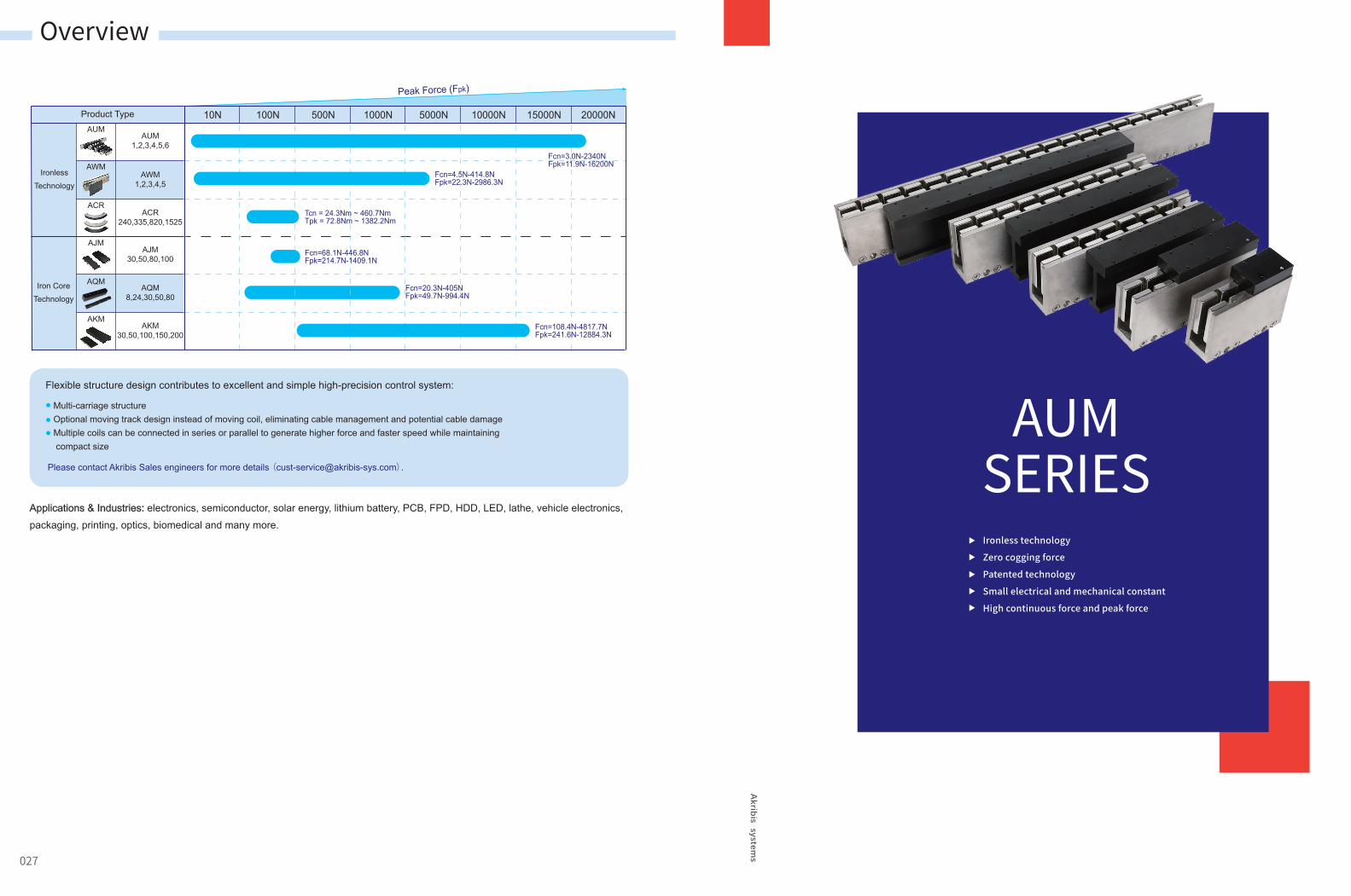
AUMSERIES
027
Overview
Ironless technology
Zero cogging force
Patented technology
Small electrical and mechanical constant
High continuous force and peak force
Flexible structure design contributes to excellent and simple high-precision control system:
Applications & Industries: electronics, semiconductor, solar energy, lithium battery, PCB, FPD, HDD, LED, lathe, vehicle electronics, packaging, printing, optics, biomedical and many more.
Multi-carriage structureOptional moving track design instead of moving coil, eliminating cable management and potential cable damageMultiple coils can be connected in series or parallel to generate higher force and faster speed while maintaining compact size
AJM30,50,80,100
AQM8,24,30,50,80
AKM30,50,100,150,200
AUM1,2,3,4,5,6
AWM1,2,3,4,5
ACR240,335,820,1525
Product Type 10N 100N 500N 1000N 5000N 10000N 15000N 20000N
Fpk=11.9N-16200NFcn=3.0N-2340N
Fcn=4.5N-414.8NFpk=22.3N-2986.3N
Tcn = 24.3Nm ~ 460.7NmTpk = 72.8Nm ~ 1382.2Nm
Fcn=68.1N-446.8NFpk=214.7N-1409.1N
Fcn=20.3N-405NFpk=49.7N-994.4N
Fcn=108.4N-4817.7NFpk=241.6N-12884.3N
AUM
AWM
ACR
AJM
AQM
AKM
Peak Force (Fpk)
IronlessTechnology
Iron Core Technology
Please contact Akribis Sales engineers for more details ([email protected]).
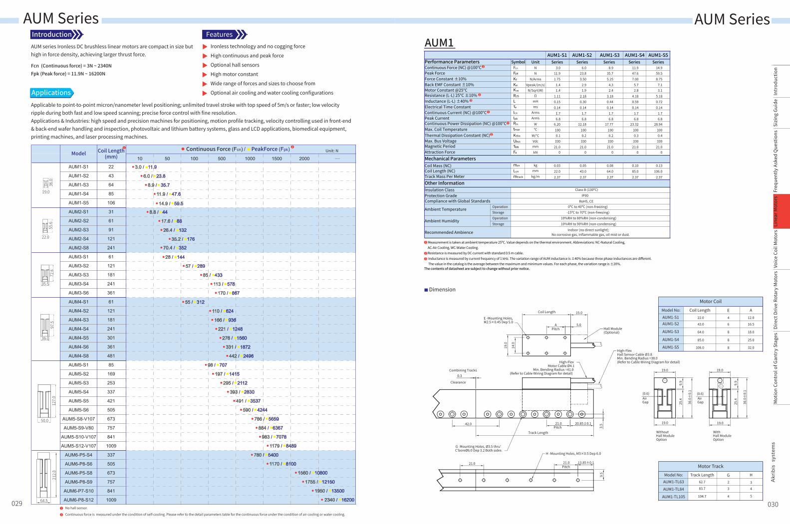
Motor Coil
Model No: Coil Length E A
22.0 4 12.0
16.5
18.0
25.0
6
8
8
43.0
64.0
85.0
AUM1-S1AUM1-S2
AUM1-S3
AUM1-S4
32.08106.0AUM1-S5
Motor TrackModel No: Track Length G H
62.7 2 3
4
5
3
4
83.7
104.7
AUM1-TL63
AUM1-TL84
AUM1-TL105
AUM Series AUM Series
3.011.91.75
1.41.4
1.110.150.14
1.76.8
6.201000.1
33021.0
0
0.0322.02.37
6.023.83.50
2.91.9
2.180.300.14
1.76.8
12.181000.2
33021.0
0
0.0543.02.37
8.935.75.25
4.32.4
3.180.440.14
1.76.8
17.771000.2
33021.0
0
0.0864.02.37
AUM1-S1 AUM1-S2 AUM1-S3UnitPerformance Parameters
Mechanical Parameters
Other Information
Continuous Force (NC) @100°CPeak ForceForce Constant ±10%Back EMF Constant ±10%Motor Constant @25°C
Electrical Time ConstantContinuous Current (NC) @100°CPeak CurrentContinuous Power Dissipation (NC) @100°CMax. Coil TemperatureThermal Dissipation Constant (NC)Max. Bus VoltageMagnetic PeriodAttraction Force
Coil Mass (NC)
Track Mass Per Meter
Insulation ClassProtection Grade
Ambient Temperature
Ambient Humidity
Recommended Ambience
Coil Length (NC)
Resistance (L-L) 25°C ±10%Inductance (L-L) ±40%
Compliance with Global Standards
SymbolFcn
Fpk
Kf
Ke
Km
R25
τe
Icn
Ipk
Pcn
tmax
Kthn
Ubus
τNN
Fa
L
mcn
Lcn
mtrack
NN
N/ArmsVpeak/(m/s)
N/Sqrt(W)Ω
mHms
ArmsArms
W℃
W/℃VdcmmkN
kg
kg/mmm
OperationStorageOperationStorage
Class B (130ºC)IP00
RoHS, CE0ºC to 40ºC (non-freezing)
-15ºC to 70ºC (non-freezing)10%RH to 80%RH (non-condensing)10%RH to 90%RH (non-condensing)
Indoor (no direct sunlight);No corrosive gas, inflammable gas, oil mist or dust.
Series Series Series11.947.67.00
5.72.8
4.180.590.14
1.76.8
23.321000.3
33021.0
0
0.1085.02.37
AUM1-S4Series
14.959.58.75
7.13.1
5.180.720.14
1.76.8
28.941000.4
33021.0
0
0.13106.0
2.37
AUM1-S5Series
1
23
Measurement is taken at ambient temperature 25ºC. Value depends on the thermal environment. Abbreviations: NC-Natural Cooling,AC-Air Cooling, WC-Water Cooling.Resistance is measured by DC current with standard 0.5 m cable.Inductance is measured by current frequency of 1 kHz. The variation range of AUM inductance is ±40% because three phase inductances are different.The value in the catalog is the average between the maximum and minimum values. For each phase, the variation range is ±20%.
The contents of datasheet are subject to change without prior notice.
2
3
1
1
1
1
Dimension
AUM1
0.3Combining Tracks
Clearance
Track Length
20.85±0.121.0Pitch
42.0
21.0 21.0Pitch
13.85±0.1
9.5
H -Mounting Holes, M3×0.5 Dep 6.0
G -Mounting Holes, Ø3.5 thru'C'boreØ6.0 Dep 3.2 Both sides
19.0
36.0
±0.
1
9.9
25.4
(0.6)AirGap
19.0
14.0
19.0
Coil Length
5.0APitch
E -Mounting Holes, M2.5×0.45 Dep 5.0
High-Flex Motor Cable Ø4.1
Min. Bending Radius =41.0(Refer to Cable Wiring Diagram for detail)
15.0
Hall Module(Optional)
High-Flex Hall Sensor Cable Ø3.8Min. Bending Radius =38.0(Refer to Cable Wiring Diagram for detail)
3.5 19.0
36.0
±0.
1
9.9
25.4
(0.6)AirGap
19.0
Without Hall ModuleOption
WithHall ModuleOption
029
Intr
oduc
tion
Sizi
ng G
uide
Freq
uent
ly A
sked
Que
stio
nsVo
ice
Coil
Mot
ors
Dire
ct D
rive
Rota
ry M
otor
sM
otio
n Co
ntro
l of G
antr
y St
ages
Line
ar M
otor
s
030
AUM series Ironless DC brushless linear motors are compact in size but high in force density, achieving larger thrust force.
Introduction
Applicable to point-to-point micron/nanometer level positioning; unlimited travel stroke with top speed of 5m/s or faster; low velocity ripple during both fast and low speed scanning; precise force control with fine resolution.Applications & Industries: high speed and precision machines for positioning, motion profile tracking, velocity controlling used in front-end & back-end wafer handling and inspection, photovoltaic and lithium battery systems, glass and LCD applications, biomedical equipment, printing machines, and laser processing machines.
Applications
Ironless technology and no cogging force
High continuous and peak force
Optional hall sensors
High motor constant
Wide range of forces and sizes to choose from
Optional air cooling and water cooling configurations
Features
Fcn (Continuous force) = 3N ~ 2340NFpk (Peak force) = 11.9N ~ 16200N
Model
AUM1-S1
AUM1-S2
AUM1-S3
AUM1-S4
AUM1-S5
AUM2-S1
AUM2-S2
AUM2-S3
AUM2-S4
AUM2-S8
AUM3-S1
AUM3-S2
AUM3-S3
AUM3-S4
AUM3-S6
AUM4-S1
AUM4-S2
AUM4-S3
AUM4-S4
AUM4-S5
AUM4-S6
AUM4-S8
AUM5-S1
AUM5-S2
AUM5-S3
AUM5-S4
AUM5-S5
AUM5-S6
AUM5-S8-V107
AUM5-S9-V80
AUM5-S10-V107
AUM5-S12-V107
AUM6-P5-S4
AUM6-P8-S6
AUM6-P5-S8
AUM6-P8-S9
AUM6-P7-S10
AUM6-P8-S12
22
43
64
85
106
31
61
91
121
241
61
121
181
241
361
61
121
181
241
301
361
481
85
169
253
337
421
505
673
757
841
1009
337
505
673
757
841
1009
Coil Length(mm)
1
10 50 100 500 1000 1500 2000 ....
19.0
36.0
22.0
55.6
35.5
72.6
39.0
97.5
50.0
127.0
64.5
212.0
Unit: NContinuous Force (Fcn) / PeakForce (Fpk)
1 No hall sensor.
2 Continuous force is measured under the condition of self-cooling. Please refer to the detail parameters table for the continuous force under the condition of air cooling or water cooling.
3.0 / 11.9
6.0 / 23.8
8.9 / 35.7
11.9 / 47.6
14.9 / 59.5
8.8 / 44
17.6 / 88
26.4 / 132
35.2 / 176
70.4 / 352
28 / 144
57 / 289
85 / 433
113 / 578
170 / 867
55 / 312
110 / 624
166 / 936
221 / 1248
276 / 1560
331 / 1872
442 / 2496
98 / 707
197 / 1415
295 / 2112
393 / 2830
491 / 3537
590 / 4244
786 / 5659
884 / 6367
983 / 7078
1179 / 8489
780 / 5400
1170 / 8100
1560 / 10800
1755 / 12150
1950 / 13500
2340 / 16200
2
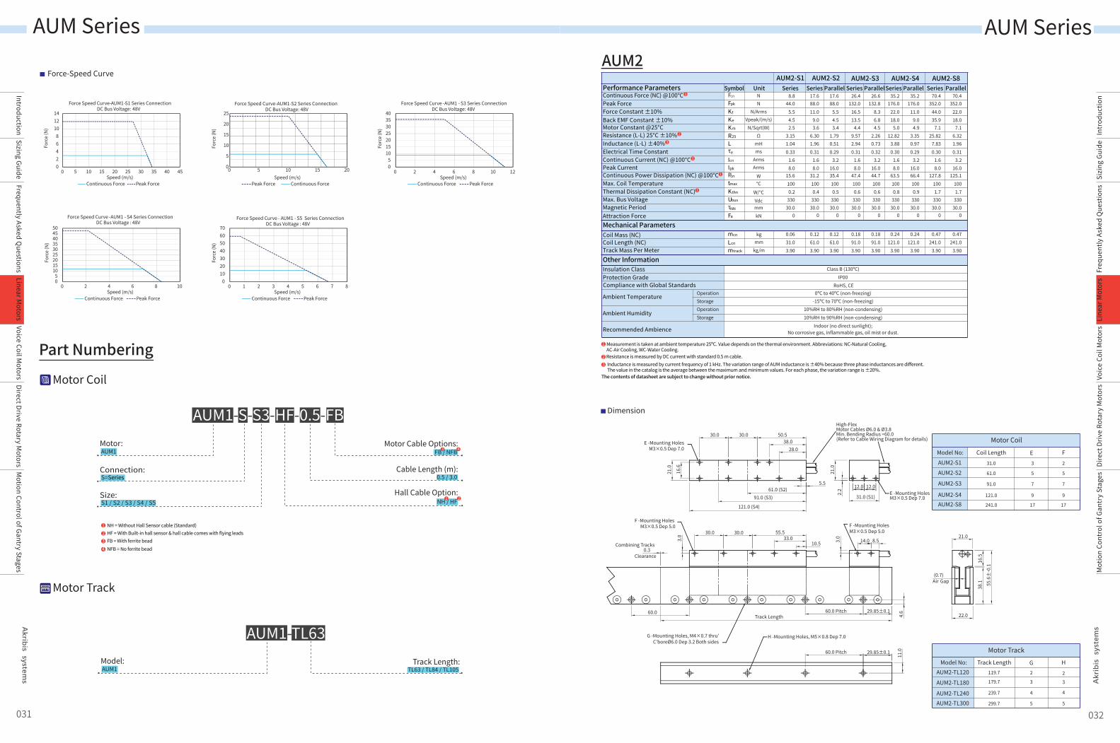
AUM1Motor:
Connection:
S1 / S2 / S3 / S4 / S5Size:
Cable Length (m):0.5 / 3.0
Hall Cable Option:
Motor Cable Options:FB / NFB
AUM1-S-S3-HF-0.5-FB
Part Numbering
Force-Speed Curve
Dimension
26.6132.8
8.36.84.5
2.260.730.32
3.216.044.71000.6
33030.0
0
0.1891.03.90
Parallel Parallel Parallel35.2
176.022.018.0
5.012.82
3.880.30
1.68.0
63.51000.8
33030.0
0
0.24121.0
3.90
35.2176.0
11.09.04.9
3.350.970.29
3.216.066.41000.9
33030.0
0
0.24121.0
3.90
AUM2-S4Series
70.4352.0
44.035.9
7.125.82
7.830.30
1.68.0
127.81001.7
33030.0
0
0.47241.0
3.90
70.4352.0
22.018.0
7.16.321.960.31
3.216.0
125.11001.7
33030.0
0
0.47241.0
3.90
AUM2-S8Series
17.688.011.0
9.03.6
6.301.960.31
1.68.0
31.21000.4
33030.0
0
0.1261.03.90
17.688.0
5.54.53.4
1.790.510.29
3.216.035.41000.5
33030.0
0
0.1261.03.90
26.4132.0
16.513.5
4.49.572.940.31
1.68.0
47.41000.6
33030.0
0
0.1891.03.90
AUM2-S2 AUM2-S3Series Parallel Series
8.844.0
5.54.52.5
3.151.040.33
1.68.0
15.61000.2
33030.0
0
0.0631.03.90
AUM2-S1UnitPerformance Parameters
Mechanical Parameters
Other Information
Continuous Force (NC) @100°CPeak ForceForce Constant ±10%Back EMF Constant ±10%Motor Constant @25°C
Electrical Time ConstantContinuous Current (NC) @100°CPeak CurrentContinuous Power Dissipation (NC) @100°CMax. Coil TemperatureThermal Dissipation Constant (NC)Max. Bus VoltageMagnetic PeriodAttraction Force
Coil Mass (NC)
Track Mass Per Meter
Insulation ClassProtection Grade
Ambient Temperature
Ambient Humidity
Recommended Ambience
Coil Length (NC)
Resistance (L-L) 25°C ±10%Inductance (L-L) ±40%
Compliance with Global Standards
Fcn
Fpk
Kf
Ke
Km
R25
τe
Icn
Ipk
Pcn
tmax
Kthn
Ubus
τNN
Fa
L
SymbolNN
N/ArmsVpeak/(m/s)
N/Sqrt(W)Ω
mHms
ArmsArms
W℃
W/℃VdcmmkN
mcn
Lcn
mtrack
kg
kg/mmm
OperationStorageOperationStorage
Class B (130ºC) IP00
RoHS, CE0ºC to 40ºC (non-freezing)
-15ºC to 70ºC (non-freezing)10%RH to 80%RH (non-condensing)10%RH to 90%RH (non-condensing)
Indoor (no direct sunlight);No corrosive gas, inflammable gas, oil mist or dust.
Series
1
23
Measurement is taken at ambient temperature 25ºC. Value depends on the thermal environment. Abbreviations: NC-Natural Cooling,AC-Air Cooling, WC-Water Cooling.Resistance is measured by DC current with standard 0.5 m cable.Inductance is measured by current frequency of 1 kHz. The variation range of AUM inductance is ±40% because three phase inductances are different.The value in the catalog is the average between the maximum and minimum values. For each phase, the variation range is ±20%.
The contents of datasheet are subject to change without prior notice.
AUM2
Motor Coil
Model No: Coil Length E F
31.0 3 2
5
7
9
5
7
9
61.0
91.0
121.0
AUM2-S1AUM2-S2
AUM2-S3
AUM2-S41717241.0AUM2-S8
Motor TrackModel No: Track Length G H
119.7 2 2
3
4
5
3
4
5
179.7
239.7
299.7
AUM2-TL120
AUM2-TL180
AUM2-TL240AUM2-TL300
10.533.0
55.530.030.0
5.5
28.038.0
50.530.030.0
21.0
16.6
61.0 (S2)91.0 (S3)
121.0 (S4)
31.0 (S1)
3.0
3.0
2.2
21.0
14.0 8.5
22.0
16.5
38.1
(0.7)Air Gap
21.0
Track Length29.85±0.160.0 Pitch
60.0 Pitch
0.3Combining Tracks
Clearance
60.0 4.6
11.0
E -Mounting HolesM3×0.5 Dep 7.0
E -Mounting HolesM3×0.5 Dep 7.0
F -Mounting HolesM3×0.5 Dep 5.0 F -Mounting Holes
M3×0.5 Dep 5.0
G -Mounting Holes, M4×0.7 thru'C'boreØ6.0 Dep 3.2 Both sides
H -Mounting Holes, M5×0.8 Dep 7.0
High-Flex Motor Cables Ø6.0 & Ø3.8Min. Bending Radius =60.0(Refer to Cable Wiring Diagram for details)
55.6
±-0
.1
29.85±0.1
12.0 12.0
0
5
10
15
20
25
0 5 10 15 20
Forc
e (N
)
Force Speed Curve-AUM1-S2 Series Connection DC Bus Voltage: 48V
Peak Force Continuous ForceSpeed (m/s)
123
NH = Without Hall Sensor cable (Standard)HF = With Built-in hall sensor & hall cable comes with flying leadsFB = With ferrite bead
4 NFB = No ferrite bead
NH / HF
02468
101214
0 5 10 15 20 25 30 35 40 45
Forc
e (N
)
Force Speed Curve-AUM1-S1 Series ConnectionDC Bus Voltage: 48V
Continuous Force Peak ForceSpeed (m/s)
05
10152025303540
0 2 4 6 8 10 12
Forc
e (N
)
Force Speed Curve -AUM1 - S3 Series ConnectionDC Bus Voltage: 48V
Continuous Force Peak ForceSpeed (m/s)
05
101520253035404550
0 2 4 6 8 10
Forc
e (N
)
Force Speed Curve -AUM1 - S4 Series ConnectionDC Bus Voltage : 48V
Continuous Force Peak ForceSpeed (m/s)
010203040506070
0 1 2 3 4 5 6 7 8
Forc
e (N
)Force Speed Curve - AUM1 - S5 Series Connection
DC Bus Voltage : 48V
Continuous Force Peak ForceSpeed (m/s)
031 032
Motor Coil
Motor Track
AUM1Model: Track Length:
TL63 / TL84 / TL105
AUM1-TL63
S=Series
2
3 4
1
2
3
1
1
1
1
AUM Series AUM Series
IntroductionSizing Guide
Frequently Asked Questions
Voice Coil Motors
Direct Drive Rotary Motors
Motion Control of Gantry Stages
Linear Motors
Intr
oduc
tion
Sizi
ng G
uide
Freq
uent
ly A
sked
Que
stio
nsVo
ice
Coil
Mot
ors
Dire
ct D
rive
Rota
ry M
otor
sM
otio
n Co
ntro
l of G
antr
y St
ages
Line
ar M
otor
s
Part Numbering
AUM2Motor:
S=Series / P=ParallelConnection:
S1 / S2 / S3 / S4 / S8Size:
Cable Length (m):
Thermal Sensor:K=PT100(RTD)
Hall Cable Option:NH / HF
Motor Cable Options:
AUM2-S-S3-K-HF-0.5-FB
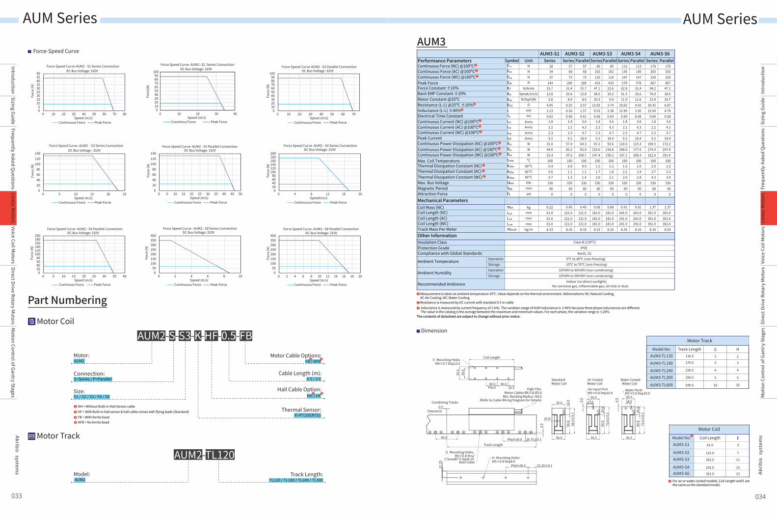
Force-Speed Curve
Dimension
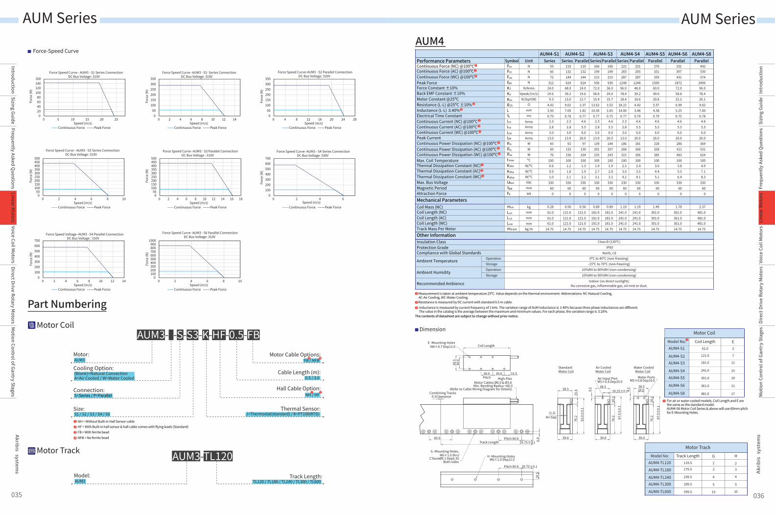
AUM3
1
23
Measurement is taken at ambient temperature 25ºC. Value depends on the thermal environment. Abbreviations: NC-Natural Cooling,AC-Air Cooling, WC-Water Cooling.Resistance is measured by DC current with standard 0.5 m cable.Inductance is measured by current frequency of 1 kHz. The variation range of AUM inductance is ±40% because three phase inductances are different.The value in the catalog is the average between the maximum and minimum values. For each phase, the variation range is ±20%.
The contents of datasheet are subject to change without prior notice.
Other InformationInsulation ClassProtection Grade
Ambient Temperature
Ambient Humidity
Recommended Ambience
Compliance with Global StandardsOperationStorageOperationStorage
Class B (130ºC) IP00
RoHS, CE0ºC to 40ºC (non-freezing)
-15ºC to 70ºC (non-freezing)10%RH to 80%RH (non-condensing)10%RH to 90%RH (non-condensing)
Indoor (no direct sunlight);No corrosive gas, inflammable gas, oil mist or dust.
Continuous Force (NC) @100ºCContinuous Force (AC) @100ºCContinuous Force (WC) @100ºCPeak ForceForce Constant ±10%
Resistance (L-L) @25ºC ±10%Inductance (L-L) ±40%Electrical Time ConstantContinuous Current (NC) @100ºCContinuous Current (AC) @100ºCContinuous Current (WC) @100ºCPeak CurrentContinuous Power Dissipation (NC) @100ºCContinuous Power Dissipation (AC) @100ºC
Back EMF Constant ±10%Motor Constant @25ºC
Continuous Power Dissipation (WC) @100ºCMax. Coil TemperatureThermal Dissipation Constant (NC)
Max. Bus VoltageMagnetic PeriodAttraction Force
Thermal Dissipation Constant (AC)Thermal Dissipation Constant (WC)
Performance Parameters
Mechanical ParametersCoil Mass (NC)
Coil Length (AC) Coil Length (NC)
Track Mass Per MeterCoil Length (WC)
NNNN
N/ArmsVpeak/(m/s)
N/Sqrt(W)Ω
mHms
ArmsArmsArmsArms
WWWºC
W/ºCW/ºCW/ºCVdcmmkN
Parallel Parallel SeriesAUM3-S4
SeriesAUM3-S6AUM3-S2 AUM3-S3
Series Parallel SeriesAUM3-S1
UnitSymbol SeriesFcn
Fca
Fcw
Fpk
Kf
Ke
Km
R25
Icn
Ica
Icw
Ipk
Lτe
Pcw
Pca
Pcn
tmax
Kthn
Ktha
Kthw
Ubus
τNN
Fa
mcn
Lcn
Lca
Lcw
mtrack
kg
mmmm
85102110433
23.619.2
9.93.742.380.64
3.64.34.7
18.493.6
134.8158.2
1001.21.82.1
33060
0
0.68181.0181.0181.0
8.33
113136147578
62.851.311.9
18.6212.90
0.691.82.22.39.2
116.6168.0197.1
1001.62.22.6
33060
0
0.91241.0241.0241.0
8.33
113136147578
31.425.611.64.923.360.68
3.64.34.7
18.4123.3177.6208.4
1001.62.42.8
33060
0
0.91241.0241.0241.0
8.33
170203220867
94.276.913.9
30.4219.50
0.641.82.22.39.2
190.5274.4322.0
1002.53.74.3
33060
0
1.37361.0361.0361.0
8.33
Parallel170203220867
47.138.514.76.874.700.68
3.64.34.7
18.4172.2247.9291.0
1002.33.33.9
33060
0
1.37361.0361.0361.0
8.33
576873
28931.425.6
8.49.226.260.68
1.82.22.39.2
57.8
97.61000.81.11.3
33060
0
83.2
0.45121.0121.0121.0
8.33
576873
28915.712.8
8.02.571.570.61
3.64.34.7
18.464.392.6
108.71000.91.21.4
33060
0
0.45121.0121.0121.0
8.33
85102110433
47.138.510.3
13.929.530.68
1.82.22.39.2
87.2125.6147.4
1001.21.72.0
33060
0
0.68181.0181.0181.0
8.33mm
kg/m
283437
14415.712.8
5.84.953.130.63
1.82.22.39.2
31.044.652.41000.40.60.7
33060
0
0.2261.061.061.08.33
35.5
35.0
28.0
35.0
30.030.0Pitch
Coil Length
15.5
E -Mounting HolesM4×0.7 Dep12.0
68.5
±0.
116
.5
(0.9)
4.5
0.5Combining Tracks
Clearance
29.75±0.1Pitch 60.0Track Length
60.0
High-Flex Motor Cables Ø6.0 & Ø3.8
Min. Bending Radius =60.0
35.5
35.0
72.6
±0.
120.6
50.8
50.8
35.5
35.0
72.6
±0.
120.6
50.8
4.5
4.5
Air Input Port M5×0.8 Dep10.0
Water Ports M5×0.8 Dep10.0
Standard Motor Coil
Air Cooled Motor Coil
Water Cooled Motor Coil
14.5
22.25±0.1Pitch 60.0
H -Mounting Holes M5×0.8 Dep8.0
G -Mounting Holes, M5×0.8 thru'
C'boreØ7.5 Dep6.35 Both sides
17.5(Refer to Cable Wiring Diagram for Details)
17.7
5
Motor Coil
Model No: Coil Length E61.0 3
7
11
15
121.0
181.0
241.0
AUM3-S1
AUM3-S2AUM3-S3
AUM3-S423361.0AUM3-S6
Motor TrackModel No: Track Length G H
119.5 2 2
3
4
5
10
3
4
5
10
179.5
239.5
299.5
599.5
AUM3-TL120
AUM3-TL180
AUM3-TL240AUM3-TL300
AUM3-TL600
For air or water cooled models, Coil Length and E are the same as the standard model.
1
123
NH = Without Built-in Hall Sensor cableHF = With Built-in hall sensor & hall cable comes with flying leads (Standard)FB = With ferrite bead
4 NFB = No ferrite bead
05
101520253035404550
0 10 20 30 40 50 60 70 80
Forc
e (N
)
Force Speed Curve-AUM2 - S1 Series ConnectionDC Bus Voltage: 310V
Continuous Force Peak ForceSpeed (m/s)
0102030405060708090
100
0 10 20 30 40 50 60 70
Forc
e (N
)
Force Speed Curve-AUM2 - S2 Parallel ConnectionDC Bus Voltage: 310V
Continuous Force Peak ForceSpeed (m/s)
020406080
100120140
0 5 10 15 20 25
Forc
e (N
)
Force Speed Curve -AUM2 - S3 Series ConnectionDC Bus Voltage : 310V
Continuous Force Peak ForceSpeed (m/s)
020406080
100120140
0 5 10 15 20 25 30 35 40 45 50
Forc
e (N
)Force Speed Curve -AUM2 - S3 Parallel Connection
DC Bus Voltage: 310V
Continuous Force Peak ForceSpeed (m/s)
020406080
100120140160180200
0 4 8 12 16 20
Forc
e (N
)
Force Speed Curve -AUM2 - S4 Series ConnectionDC Bus Voltage: 310V
Continuous Force Peak ForceSpeed(m/s)
020406080
100120140160180200
0 5 10 15 20 25 30 35 40
Forc
e (N
)
Force Speed Curve -AUM2 - S4 Parallel ConnectionDC Bus Voltage: 310V
Continuos Force Peak ForceSpeed (m/s)
0102030405060708090
100
0 10 20 30 40
Forc
e(N)
Speed (m/s)
Force Speed Curve- AUM2 -S2 Series Connection DC Bus Voltage: 310V
Conutious Force Peak Force
050
100150200250300350400
0 2 4 6 8 10
Forc
e (N
)
Force Speed Curve - AUM2 - S8 Series ConnectionDC Bus Voltage: 310V
Continuous Force Peak ForceSpeed (m/s)
050
100150200250300350400
0 2 4 6 8 10 12 14 16 18 20
Forc
e (N
)
Force Speed Curve -AUM2 - S8 Parallel ConnectionDC Bus Voltage: 310V
Continuous Force Peak ForceSpeed (m/s)
033 034
Motor Coil
Motor Track
AUM2Model: Track Length:
TL120 / TL180 / TL240 / TL300
AUM2-TL120
0.5 / 3.0
FB / NFB
2
3 4
1
2
3
1
1
1
1
1
1
1
1
1
1
1
1
1
AUM Series AUM Series
IntroductionSizing Guide
Frequently Asked Questions
Voice Coil Motors
Direct Drive Rotary Motors
Motion Control of Gantry Stages
Linear Motors
Intr
oduc
tion
Sizi
ng G
uide
Freq
uent
ly A
sked
Que
stio
nsVo
ice
Coil
Mot
ors
Dire
ct D
rive
Rota
ry M
otor
sM
otio
n Co
ntro
l of G
antr
y St
ages
Line
ar M
otor
s
Dimension
1
23
Measurement is taken at ambient temperature 25ºC. Value depends on the thermal environment. Abbreviations: NC-Natural Cooling,AC-Air Cooling, WC-Water Cooling.Resistance is measured by DC current with standard 0.5 m cable.Inductance is measured by current frequency of 1 kHz. The variation range of AUM inductance is ±40% because three phase inductances are different.The value in the catalog is the average between the maximum and minimum values. For each phase, the variation range is ±20%.
The contents of datasheet are subject to change without prior notice.
Other InformationInsulation ClassProtection Grade
Ambient Temperature
Ambient Humidity
Recommended Ambience
Compliance with Global StandardsOperationStorageOperationStorage
Class B (130ºC) IP00
RoHS, CE0ºC to 40ºC (non-freezing)
-15ºC to 70ºC (non-freezing)10%RH to 80%RH (non-condensing)10%RH to 90%RH (non-condensing)
Indoor (no direct sunlight);No corrosive gas, inflammable gas, oil mist or dust.
Continuous Force (NC) @100ºCContinuous Force (AC) @100ºCContinuous Force (WC) @100ºCPeak ForceForce Constant ±10%
Resistance (L-L) @25ºC ±10%Inductance (L-L) ±40%Electrical Time ConstantContinuous Current (NC) @100ºCContinuous Current (AC) @100ºCContinuous Current (WC) @100ºCPeak CurrentContinuous Power Dissipation (NC) @100ºCContinuous Power Dissipation (AC) @100ºC
Back EMF Constant ±10%Motor Constant @25ºC
Continuous Power Dissipation (WC) @100ºCMax. Coil TemperatureThermal Dissipation Constant (NC)
Max. Bus VoltageMagnetic PeriodAttraction Force
Thermal Dissipation Constant (AC)Thermal Dissipation Constant (WC)
Performance Parameters
Mechanical ParametersCoil Mass (NC)
Coil Length (AC) Coil Length (NC)
Track Mass Per Meter Coil Length (WC)
N
NN
N/ArmsVpeak/(m/s)
N/Sqrt(W)Ω
mHms
ArmsArmsArmsArms
WWWºC
W/ºCW/ºCW/ºCVdcmmkN
Parallel Parallel ParallelAUM4-S4
SeriesAUM4-S5AUM4-S2 AUM4-S3
Series Parallel SeriesAUM4-S1
UnitSymbol SeriesFcn
Fcw
Fpk
Kf
Ke
Km
R25
Icn
Ica
Icw
Ipk
Lτe
Pcw
Pca
Pcn
t max
Kthn
Ktha
Kthw
Ubus
τNN
Fa
mcn
Lcn
Lca
Lcw
mtrack
kg
mmmm
166
215936
36.029.415.73.522.650.75
4.65.56.0
26.01442072431001.92.83.2
33060
0
0.89181.0181.0181.014.75
221
287124896.078.418.4
18.2214.00
0.772.32.83.0
13.01862683151002.53.64.2
33060
0
1.19241.0241.0241.014.75
221
287124848.039.218.64.423.480.79
4.65.56.0
26.01812603061002.43.54.1
33060
0
1.19241.0241.0241.014.75
276
359156060.049.020.85.574.380.79
4.65.56.0
26.02283283851003.04.45.1
33060
0
1.49301.0301.0301.014.75
ParallelAUM4-S6
331
431187272.058.822.26.995.250.75
4.65.56.0
26.02864124831003.85.56.4
33060
0
1.78361.0361.0361.014.75
ParallelAUM4-S8
442
574249696.078.426.19.027.000.78
4.65.56.0
26.03695316241004.97.18.3
33060
0
2.37481.0481.0481.014.75
110
144624
48.039.213.09.027.000.78
2.32.83.0
13.092
1561001.21.82.1
33060
0
133
0.56121.0121.0121.014.75
110
144624
24.019.612.72.371.820.77
4.65.56.0
26.097
1391641001.31.92.2
33060
0
0.56121.0121.0121.014.75
166
215936
72.058.815.9
13.6210.50
0.772.32.83.0
13.01392012351001.92.73.1
33060
0
0.89181.0181.0181.014.75
mmkg/m
55
72312
24.019.6
9.34.423.500.79
2.32.83.0
13.0456576
1000.60.91.0
33060
0
0.2861.061.061.0
14.75
AUM4
Motor Coil
Model No: Coil Length E61.0 3
7
11
15
19
11
121.0
181.0
241.0
301.0
361.0
AUM4-S1
AUM4-S2AUM4-S3
AUM4-S4AUM4-S5
AUM4-S6
17481.0AUM4-S8
1
Motor TrackModel No: Track Length G H
119.5 2 2
3
4
5
10
3
4
5
10
179.5
239.5
299.5
599.5
AUM4-TL120
AUM4-TL180
AUM4-TL240AUM4-TL300
AUM4-TL600
93.0
±0.
1
39.0
38.5
15.6
(1.2)
30.0
38.5
15.530.0Pitch
Coil Length
6.0
0.5Combining Tracks
Clearance
29.75±0.1Pitch 60.0
Track Length60.0
Air Gap
76.2
30.0
29.75±0.1Pitch 60.0
19.5
39.0
38.5
20.1
4.5
76.2
39.0
38.516.0
20.1
4.5
76.2
Standard Motor Coil
Air Cooled Motor Coil
Water Cooled Motor Coil
97.5
±0.
1
97.5
±0.
1
High-Flex Motor Cables Ø6.0 & Ø3.8
Min. Bending Radius =60.0(Refer to Cable Wiring Diagram for Details)
E -Mounting HolesM4×0.7 Dep12.0
G -Mounting Holes, M6×1.0 thru'
C'boreØ9.1 Dep6.35Both sides
H -Mounting Holes M6×1.0 Dep12.0
Air Input PortM5×0.8 Dep10.0
Water PortsM5×0.8 Dep10.0
19.25±0.1
For air or water cooled models, Coil Length and E are the same as the standard model.AUM4-S6 Motor Coil Series & above will use 60mm pitchfor E-Mounting Holes.
1
Part Numbering
Force-Speed Curve
AUM3Motor:
S=Series / P=ParallelConnection:
(Blank)=Natural ConvectionA=Air Cooled / W=Water Cooled
Cooling Option:
S1 / S2 / S3 / S4 / S6Size:
Cable Length (m):
Thermal Sensor:J=Thermostat(standard) / K=PT100(RTD)
Hall Cable Option:
Motor Cable Options:
AUM3- -S-S3-K-HF-0.5-FB
NH / HF
123
NH = Without Built-in Hall Sensor cableHF = With Built-in hall sensor & hall cable comes with flying leads (Standard)FB = With ferrite bead
4 NFB = No ferrite bead
020406080
100120140160
0 5 10 15 20 25
Forc
e (N
)
Force Speed Curve - AUM3 - S1 Series ConnectionDC Bus Voltage: 310V
Continuous Force Peak ForceSpeed (m/s)
050
100150200250300350
0 2 4 6 8 10 12 14
Forc
e (N
)
Force Speed Curve -AUM3 - S2- Series ConnectionDC Bus Voltage: 310V
Continuous Force Peak ForceSpeed (m/s)
050
100150200250300350
0 4 8 12 16 20 24 28
Forc
e (N
)
Force Speed Curve-AUM3 - S2 Parallel ConnectionDC Bus Voltage: 310V
Continuous Force Peak ForceSpeed (m/s)
050
100150200250300350400450500
0 2 4 6 8 10
Forc
e (N
)
Force Speed Curve - AUM3 - S3 Series ConnectionDC Bus Voltage: 310V
Continuous Force Peak ForceSpeed (m/s)
050
100150200250300350400450500
0 2 4 6 8 10 12 14 16 18
Forc
e (N
)Force Speed Curve -AUM3 - S3 Parallel Connection
DC Bus Voltage : 310V
Continuous Force Peak ForceSpeed (m/s)
0100200300400500600700
0 2 4 6
Forc
e (N
)
Force Speed Curve -AUM3 - S4 Series ConnectionDC Bus Voltage: 330V
Continuous Force Peak ForceSpeed (m/s)
0100200300400500600700
0 2 4 6 8 10 12 14
Forc
e (N
)
Force Speed Voltage -AUM3 - S4 Parallel ConnectionDC Bus Voltage : 310V
Continuous Force Peak ForceSpeed (m/s)
0100200300400500600700800900
1000
0 2 4 6 8 10
Forc
e (N
)
Force Speed Curve -AUM3 - S6 Parallel ConnectionDC Bus Voltage: 310V
Continuous Force Peak ForceSpeed (m/s)
035 036
Motor Coil
Motor Track
AUM3Model: Track Length:
TL120 / TL180 / TL240 / TL300 / TL600
AUM3-TL120
0.5 / 3.0
FB / NFB
2
3 4
1
2
3
1
1
1
1
1
1
1
1
1
1
1
1
AUM Series AUM Series
IntroductionSizing Guide
Frequently Asked Questions
Voice Coil Motors
Direct Drive Rotary Motors
Motion Control of Gantry Stages
Linear Motors
Intr
oduc
tion
Sizi
ng G
uide
Freq
uent
ly A
sked
Que
stio
nsVo
ice
Coil
Mot
ors
Dire
ct D
rive
Rota
ry M
otor
sM
otio
n Co
ntro
l of G
antr
y St
ages
Line
ar M
otor
s
N 199 265 265 331 397 530132 132 19966Fca
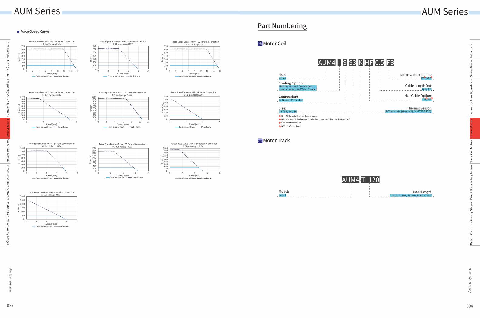
Force-Speed CurvePart Numbering
AUM4Motor:
S=Series / P=ParallelConnection:
(Blank)=Natural ConvectionA=Air Cooled / W=Water Cooled
Cooling Option:
S2 / S3 / S4 / S6Size:
Cable Length (m):
Thermal Sensor:J=Thermostat(standard) / K=PT100(RTD)
Hall Cable Option:
Motor Cable Options:
AUM4- -S-S3-K-HF-0.5-FB
NH / HF
123
NH = Without Built-in Hall Sensor cableHF = With Built-in hall sensor & hall cable comes with flying leads (Standard)FB = With ferrite bead
4 NFB = No ferrite bead
050
100150200250300350
0 2 4 6 8 10 12 14 16
Forc
e (N
)
Force Speed Curve -AUM4 - S1 Series ConnectionDC Bus Voltage: 310V
Continuous Force Peak ForceSpeed (m/s)
0100200300400500600700
0 2 4 6 8 10
Forc
e (N
)
Force Speed Curve - AUM4 - S2 Series ConnectionDC Bus Voltage: 310V
Continuous Force Peak ForceSpeed (m/s)
0100200300400500600700
0 2 4 6 8 10 12 14 16
Forc
e (N
)
Force Speed Curve - AUM4 - S2 Parallel ConnectionDC Bus Voltage : 310V
Continuous Force Peak ForceSpeed (m/s)
0100200300400500600700800900
1000
0 2 4 6
Forc
e (N
)
Force Speed Curve -AUM4 - S3 Series ConnectionDC Bus Voltage: 310V
Continuous Force Peak ForceSpeed (m/s)
0100200300400500600700800900
1000
0 2 4 6 8 10 12
Forc
e (N
)Force Speed Curve -AUM4 - S3 Parallel Connection
DC Bus Voltage: 310V
Continuous Force Peak ForceSpeed (m/s)
0200400600800
100012001400
0 2 4 6
Forc
e (N
)
Force Speed Curve -AUM4 - S4 Series ConnectionDC Bus Voltage: 310V
Continuous Force Peak ForceSpeed (m/s)
0200400600800
100012001400
0 2 4 6 8 10
Forc
e (N
)
Force Speed Curve -AUM4 - S4 Parallel ConnectionDC Bus Voltage: 310V
Continuous Force Peak ForceSpeed (m/s)
0200400600800
10001200140016001800
0 2 4 6 8
Forc
e (N
)
Force Speed Curve -AUM4 - S5 Parallel ConnectionDC Bus Voltage: 310V
Continuous Force Peak ForceSpeed (m/s)
0200400600800
100012001400160018002000
0 2 4 6 8
Forc
e (N
)
Force Speed Curve -AUM4 - S6 Parallel ConnectionDC Bus Voltage : 310V
Continuous Force Peak ForceSpeed (m/s)
0
500
1000
1500
2000
2500
3000
0 1 2 3 4 5
Forc
e (N
)
Force Speed Curve -AUM4 - S8 Parallel ConnectionDC Bus Voltage: 310V
Continuous Force Peak ForceSpeed (m/s)
037 038
Motor Coil
Motor Track
AUM4Model: Track Length:
AUM4-TL120
TL120 / TL180 / TL240 / TL300 / TL600
0.5 / 3.0
FB / NFB
2
3 4
1
AUM Series AUM Series
IntroductionSizing Guide
Frequently Asked Questions
Voice Coil Motors
Direct Drive Rotary Motors
Motion Control of Gantry Stages
Linear Motors
Intr
oduc
tion
Sizi
ng G
uide
Freq
uent
ly A
sked
Que
stio
nsVo
ice
Coil
Mot
ors
Dire
ct D
rive
Rota
ry M
otor
sM
otio
n Co
ntro
l of G
antr
y St
ages
Line
ar M
otor
s
Dimension
1
23
Measurement is taken at ambient temperature 25ºC. Value depends on the thermal environment. Abbreviations: NC-Natural Cooling,AC-Air Cooling, WC-Water Cooling.Resistance is measured by DC current with standard 0.5 m cable.Inductance is measured by current frequency of 1 kHz. The variation range of AUM inductance is ±40% because three phase inductances are different.The value in the catalog is the average between the maximum and minimum values. For each phase, the variation range is ±20%.
The contents of datasheet are subject to change without prior notice.
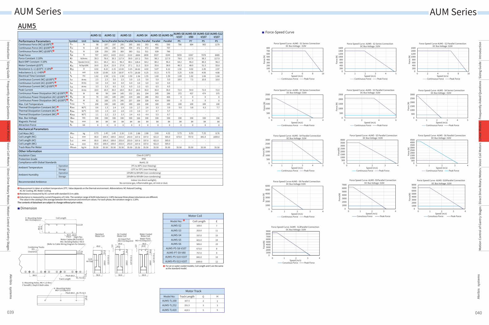
AUM5
Coil Length
21.542.0Pitch
49.0
39.0
50.0
49.0
122.
0±0.
1
21.0
(1.0)Air Gap
100.
0
0.5Combining Tracks
Clearance
7.0
41.75±0.1Pitch 84.0
Track Length
84.0
E- Mounting HolesM5×0.8 Dep12.0
High-Flex Motor Cables Ø6.0 & Ø3.8Min. Bending Radius =60.0
(Refer to Cable Wiring Diagram for Details)
50.0
49.0
127.
0±0.
1
26.0
100.
0
Air Input PortM5×0.8 Dep10.0
50.0
49.0
26.0
100.
0
Water PortsM5×0.8 Dep10.0
5.0
5.0
Standard Motor Coil
Air Cooled Motor Coil
Water Cooled Motor Coil
41.75±0.1Pitch 84.0
25.0
H -Mounting Holes M6×1.0 Dep15.0
G -Mounting Holes, M6×1.0 thru'C'boreØ9.1 Dep9.0 Both sides
24.5 21.0
127.
0±0.
1
Motor Coil
Model No: Coil Length E169.0 7
11
15
19
23
253.0
337.0
421.0
505.0
AUM5-S2
AUM5-S3
AUM5-S4
AUM5-S5AUM5-S6
8
9
10
12
673.0
757.0
841.0
1009.0
AUM5-P5-S8-V107AUM5-P7-S9-V80
AUM5-P5-S10-V107AUM5-P5-S12-V107
1
Motor TrackModel No: Track Length G H
167.5 2 2
3
5
3
5
251.5
419.5
AUM5-TL168
AUM5-TL252
AUM5-TL420
For air or water cooled models, Coil Length and E are the same as the standard model.
1
Force-Speed Curve
0100200300400500600700800
0 2 4 6 8 10
Forc
e (N
)
Force Speed Curve -AUM5 - S1 Series ConnectionDC Bus Voltage : 310V
Continuous Force Peak ForceSpeed (m/s)
0200400600800
1000120014001600
0 1 2 3 4 5
Forc
e (N
)
Force Speed Curve -AUM5 - S2 Series ConnectionDC Bus Voltage: 310V
Continuous Force Peak ForceSpeed (m/s)
0200400600800
1000120014001600
0 2 4 6 8 10
Forc
e (N
)
Force Speed Curve-AUM5 - S2 Parallel ConnectionDC Bus Voltage: 310V
Continuous Force Peak ForceSpeed (m/s)
0
500
1000
1500
2000
2500
0 1 2 3 4
Forc
e (N
)
Force Speed Curve -AUM5 - S3 Series ConnectionDC Bus Voltage: 310V
Continuous Force Peak ForceSpeed (m/s)
0
500
1000
1500
2000
2500
0 2 4 6
Forc
e (N
)
Force Speed Curve -AUM5 - S3 Parallel ConnectionDC Bus Voltage: 310V
Continuous Force Peak ForceSpeed (m/s)
0
500
1000
1500
2000
2500
3000
0 1 2 3 4 5
Forc
e (N
)
Force Speed Curve -AUM5 - S4 Series ConnectionDC Bus Voltage : 310V
Continuous Force Peak ForceSpeed (m/s)
0
500
1000
1500
2000
2500
3000
0 1 2 3 4 5
Forc
e (N
)
Force Speed Curve -AUM5 - S4 Parallel ConnectionDC Bus Voltage: 310V
Continuous Force Peak ForceSpeed (m/s)
0500
1000150020002500300035004000
0 1 2 3 4
Forc
e (N)
Force Speed Curve -AUM5 - S5 Parallel ConnectionDC Bus Voltage: 310V
Continuous Force Peak ForceSpeed (m/s)
0500
10001500200025003000350040004500
0 1 2 3 4
Forc
e (N
)
Force Speed Curve -AUM5 - S6 Parallel ConnectionDC Bus Voltage: 310V
Continuous Force Peak ForceSpeed (m/s)
0
1000
2000
3000
4000
5000
6000
0 1 2 3 4
Forc
e (N
)
Force Speed Curve-AUM5 - S8 Parallel ConnectionDC Bus Voltage:310V
Continuous Force Peak ForceSpeed (m/s)
01000200030004000500060007000
0 1 2 3 4
Forc
e(N)
Speed (m/s)
Force Speed Curve- AUM5 -S9Parallel Connection DC Bus Voltage: 310V
Conutious Force Peak Force
010002000300040005000600070008000
0 1 2 3 4
Forc
e(N)
Speed (m/s)
Force Speed Curve -AUM5 -S10Parallel Connection DC Bus Voltage: 310V
Conutious Force Peak Force
0100020003000400050006000700080009000
0 1 2 3 4
Forc
e(N)
Speed (m/s)
Force Speed Curve-AUM5 -S12Parallel Connection DC Bus Voltage: 310V
Conutious Force Peak Force
039 040
Continuous Force (NC) @100ºCContinuous Force (AC) @100ºCContinuous Force (WC) @100ºCPeak ForceForce Constant ±10%
Resistance (L-L) @25ºC ±10%Inductance (L-L) ±40%Electrical Time ConstantContinuous Current (NC) @100ºCContinuous Current (AC) @100ºCContinuous Current (WC) @100ºCPeak CurrentContinuous Power Dissipation (NC) @100ºCContinuous Power Dissipation (AC) @100ºC
Back EMF Constant ±10%Motor Constant @25ºC
Continuous Power Dissipation (WC) @100ºCMax. Coil TemperatureThermal Dissipation Constant (NC)
Max. Bus VoltageMagnetic PeriodAttraction Force
Thermal Dissipation Constant (AC)Thermal Dissipation Constant (WC)
Mechanical ParametersCoil Mass (NC)
Coil Length (AC) Coil Length (NC)
Track Mass Per MeterCoil Length (WC)
Class B (130ºC) IP00
RoHS, CE0ºC to 40ºC (non-freezing)
-15ºC to 70ºC (non-freezing)10%RH to 80%RH (non-condensing)10%RH to 90%RH (non-condensing)
Indoor (no direct sunlight);No corrosive gas, inflammable gas, oil mist or dust.
NNNN
N/ArmsVpeak/(m/s)
N/Sqrt(W)Ω
mHms
ArmsArms
ArmsArms
WWWºC
W/ºCW/ºCW/ºCVdcmm
kN
Parallel Parallel Parallel
AUM5-S4
Series
AUM5-S5 AUM5-S6AUM5-S2 AUM5-S3
Series Parallel Series
AUM5-S1
UnitSymbol SeriesFcn
Fca
Fcw
Fpk
Kf
Ke
Km
R25
Icn
Ica
Icw
Ipk
Lτe
Pcw
Pca
Pcn
t max
Kthn
Ktha
Kthw
Ubus
τNN
Fa
mcn
Lcn
Lca
Lcw
mtrack
kg
mmmm
0
295354383
212259.048.127.13.154.731.50
5.06.06.5
36.01522192571002.02.93.4
33084
2.16253.0253.0253.035.50
0
393472511
2830157.2128.4
31.516.6226.00
1.562.53.03.3
18.02012893391002.73.94.5
33084
2.88337.0337.0337.035.50
393472511
283078.664.232.04.026.251.55
5.06.06.5
36.01942803281002.63.74.4
33084
0
2.88337.0337.0337.035.50
491590639
353798.380.235.65.078.131.60
5.06.06.5
36.02453534141003.34.75.5
33084
0
3.60421.0421.0421.035.50
Parallel590707766
4244117.9
96.338.96.129.751.59
5.06.06.5
36.02964265001003.95.76.7
33084
0
4.32505.0505.0505.035.50
P5786
--
565978.664.246.31.923.251.6910.0
--
72.0372
00
1005.0
--
33084
0
5.73673.0
--
35.50
P7884
--
6367117.9
96.348.04.026.501.62
7.5--
54.0437
00
1005.8
--
33084
0
6.53757.0
--
35.50
P5983
--
707898.380.351.32.454.061.6610.0
--
72.0474
00
1006.3
--
33084
0
7.25841.0
--
35.50
P51179
--
8489117.9
96.355.82.974.881.6410.0
--
72.0575
00
1007.7
--
33084
0
8.761009.0
--
35.50
197236255
141578.664.222.48.22
13.001.58
2.53.03.3
18.099
1681001.31.92.2
33084
0
143
1.45169.0169.0169.035.50
197236255
141539.332.121.92.153.251.51
5.06.06.5
36.01041491751001.42.02.3
33084
0
1.45169.0169.0169.035.50
295354383
2122117.9
96.327.8
12.0218.97
1.582.53.03.3
18.01452092451001.92.83.3
33084
0
2.16253.0253.0253.035.50
mmkg/m
98118128707
39.332.116.04.026.501.62
2.53.03.3
18.0497082
1000.60.91.1
33084
0
0.7385.085.085.0
35.50
Performance Parameters
AUM5-S8-V107
AUM5-S9-V80
AUM5-S10-V107
AUM5-S12-V107
Other InformationInsulation ClassProtection Grade
Ambient Temperature
Ambient Humidity
Recommended Ambience
Compliance with Global StandardsOperationStorageOperationStorage
2
3
1
1
1
1
1
1
1
1
1
1
1
1
AUM Series AUM Series
IntroductionSizing Guide
Frequently Asked Questions
Voice Coil Motors
Direct Drive Rotary Motors
Motion Control of Gantry Stages
Linear Motors
Intr
oduc
tion
Sizi
ng G
uide
Freq
uent
ly A
sked
Que
stio
nsVo
ice
Coil
Mot
ors
Dire
ct D
rive
Rota
ry M
otor
sM
otio
n Co
ntro
l of G
antr
y St
ages
Line
ar M
otor
s
Dimension
Class B (130ºC) IP00
RoHS, CE0ºC to 40ºC (non-freezing)
-15ºC to 70ºC (non-freezing)10%RH to 80%RH (non-condensing)10%RH to 90%RH (non-condensing)
Indoor (no direct sunlight);No corrosive gas, inflammable gas, oil mist or dust.
UnitAUM6-P5-S4
P5780
540075.061.253.31.322.652.0010.472.02761003.7
33084
0
337.04.50
66.67
AUM6-P5-S8P5
9.00
156010800150.0122.5
72.92.825.301.8810.472.05901007.9
33084
0
673.066.67
AUM6-P8-S9P8
10.13
175512150112.5
91.979.91.322.652.0015.6
108.06221008.3
33084
0
757.066.67
AUM6-P7-S10P7
11.25
195013500150.0122.5
82.22.224.241.9113.090.07261009.7
33084
0
841.066.67
AUM6-P8-S12P8
13.50
234016200150.0122.5
90.71.823.531.9415.6
108.0857100
11.4330
840
1009.066.67
AUM6-P8-S6P8
6.75
1170810075.061.267.50.821.772.1515.6
108.03871005.2
33084
0
505.066.67
SymbolFcn
Fpk
Kf
Ke
Km
R25
Icn
Ipk
Lτe
Pcn
t max
Kthn
Ubus
τNN
Fa
Lcn
mtrack
mcn
NN
N/ArmsVpeak/(m/s)
N/Sqrt(W)Ω
mHms
ArmsArms
WºC
W/ºCVdcmmkN
mmkg
kg/m
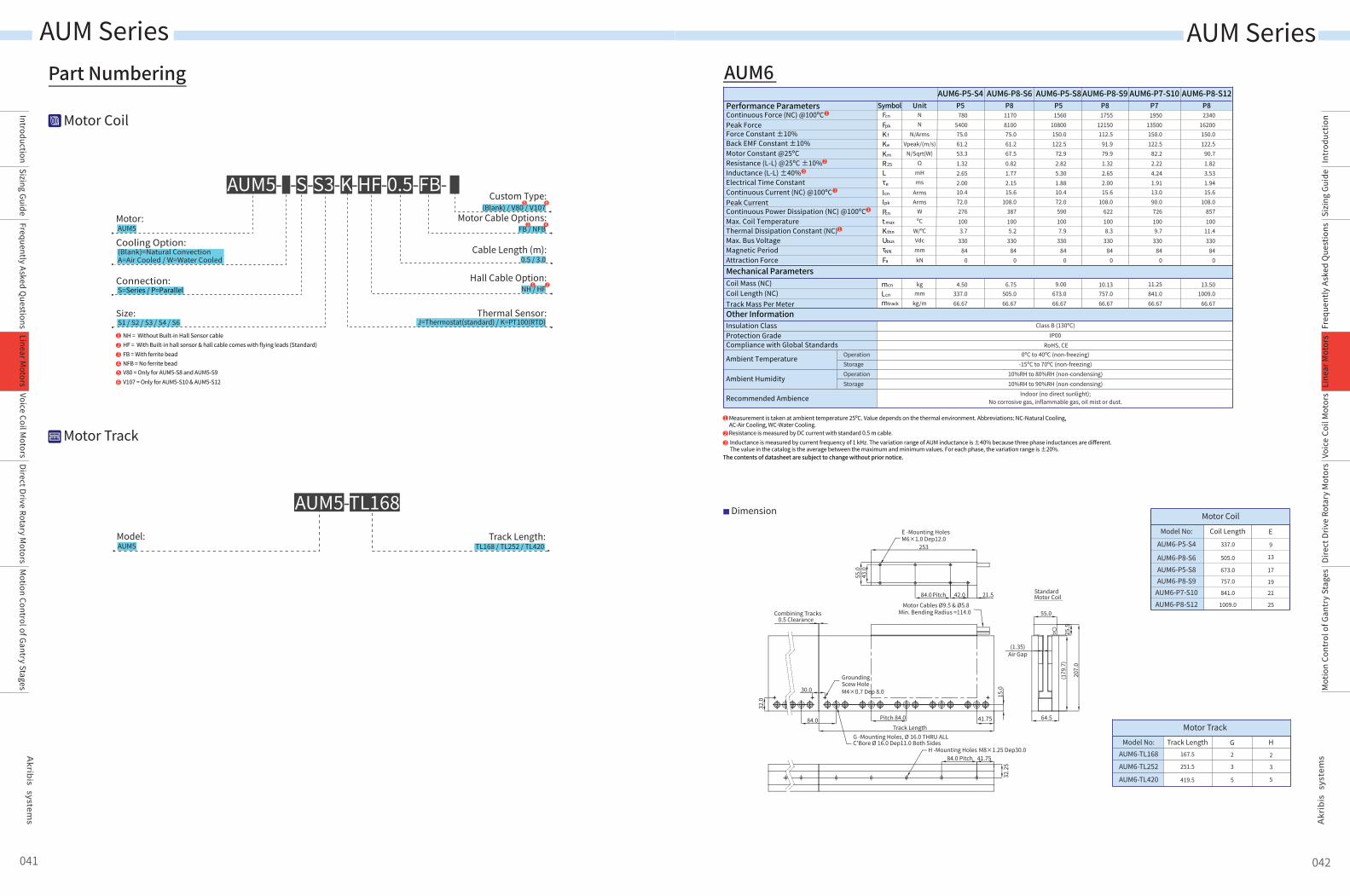
Continuous Force (NC) @100ºCPeak ForceForce Constant ±10%
Resistance (L-L) @25ºC ±10%Inductance (L-L) ±40%Electrical Time ConstantContinuous Current (NC) @100ºCPeak CurrentContinuous Power Dissipation (NC) @100ºC
Back EMF Constant ±10%Motor Constant @25ºC
Max. Coil TemperatureThermal Dissipation Constant (NC)Max. Bus VoltageMagnetic PeriodAttraction ForceMechanical Parameters
Performance Parameters
Coil Length (NC)Coil Mass (NC)
Track Mass Per MeterOther InformationInsulation ClassProtection Grade
Ambient Temperature
Ambient Humidity
Recommended Ambience
Compliance with Global StandardsOperationStorageOperationStorage
1
23
Measurement is taken at ambient temperature 25ºC. Value depends on the thermal environment. Abbreviations: NC-Natural Cooling,AC-Air Cooling, WC-Water Cooling.Resistance is measured by DC current with standard 0.5 m cable.Inductance is measured by current frequency of 1 kHz. The variation range of AUM inductance is ±40% because three phase inductances are different.The value in the catalog is the average between the maximum and minimum values. For each phase, the variation range is ±20%.
The contents of datasheet are subject to change without prior notice.
AUM6
Motor Coil
Model No: Coil Length E337.0 9
13
17
19
21
25
505.0
673.0
757.0
841.0
1009.0
AUM6-P5-S4
AUM6-P8-S6AUM6-P5-S8AUM6-P8-S9
AUM6-P7-S10AUM6-P8-S12
Motor TrackModel No: Track Length G H
167.5 2 2
3
5
3
5
251.5
419.5
AUM6-TL168
AUM6-TL252
AUM6-TL420
253
84.0
84.0 64.5
55.0
30.0
42.0 21.5PitchMotor Cables Ø9.5 & Ø5.8
Min. Bending Radius =114.0
Standard Motor Coil
41.7584.0 PitchH -Mounting Holes M8×1.25 Dep30.0
G -Mounting Holes, Ø 16.0 THRU ALLC'Bore Ø 16.0 Dep11.0 Both Sides
15.0
25.5
207.
0
(179
.7)
32.2
5
55.0
32.0
43.0
41.75Pitch 84.0Track Length
(1.35)
0.5Combining Tracks
Clearance
Air Gap
E -Mounting HolesM6×1.0 Dep12.0
GroundingScew HoleM4×0.7 Dep 8.0
Part Numbering
AUM5Motor:
S=Series / P=ParallelConnection:
(Blank)=Natural ConvectionA=Air Cooled / W=Water Cooled
Cooling Option:
S1 / S2 / S3 / S4 / S6Size:
Cable Length (m):
Thermal Sensor:J=Thermostat(standard) / K=PT100(RTD)
Hall Cable Option:
Motor Cable Options:
AUM5- -S-S3-K-HF-0.5-FB-
NH / HF
123
NH = Without Built-in Hall Sensor cableHF = With Built-in hall sensor & hall cable comes with flying leads (Standard)FB = With ferrite bead
5 V80 = Only for AUM5-S8 and AUM5-S96 V107 = Only for AUM5-S10 & AUM5-S12
4 NFB = No ferrite bead
041 042
Motor Coil
Motor Track
AUM5Model: Track Length:
TL168 / TL252 / TL420
AUM5-TL168
(Blank) / V80 / V107Custom Type:
0.5 / 3.0
FB / NFB
21
43
65
2
3
1
1
1
1
AUM Series AUM Series
IntroductionSizing Guide
Frequently Asked Questions
Voice Coil Motors
Direct Drive Rotary Motors
Motion Control of Gantry Stages
Linear Motors
Intr
oduc
tion
Sizi
ng G
uide
Freq
uent
ly A
sked
Que
stio
nsVo
ice
Coil
Mot
ors
Dire
ct D
rive
Rota
ry M
otor
sM
otio
n Co
ntro
l of G
antr
y St
ages
Line
ar M
otor
s
Force-Speed Curve
Part Numbering
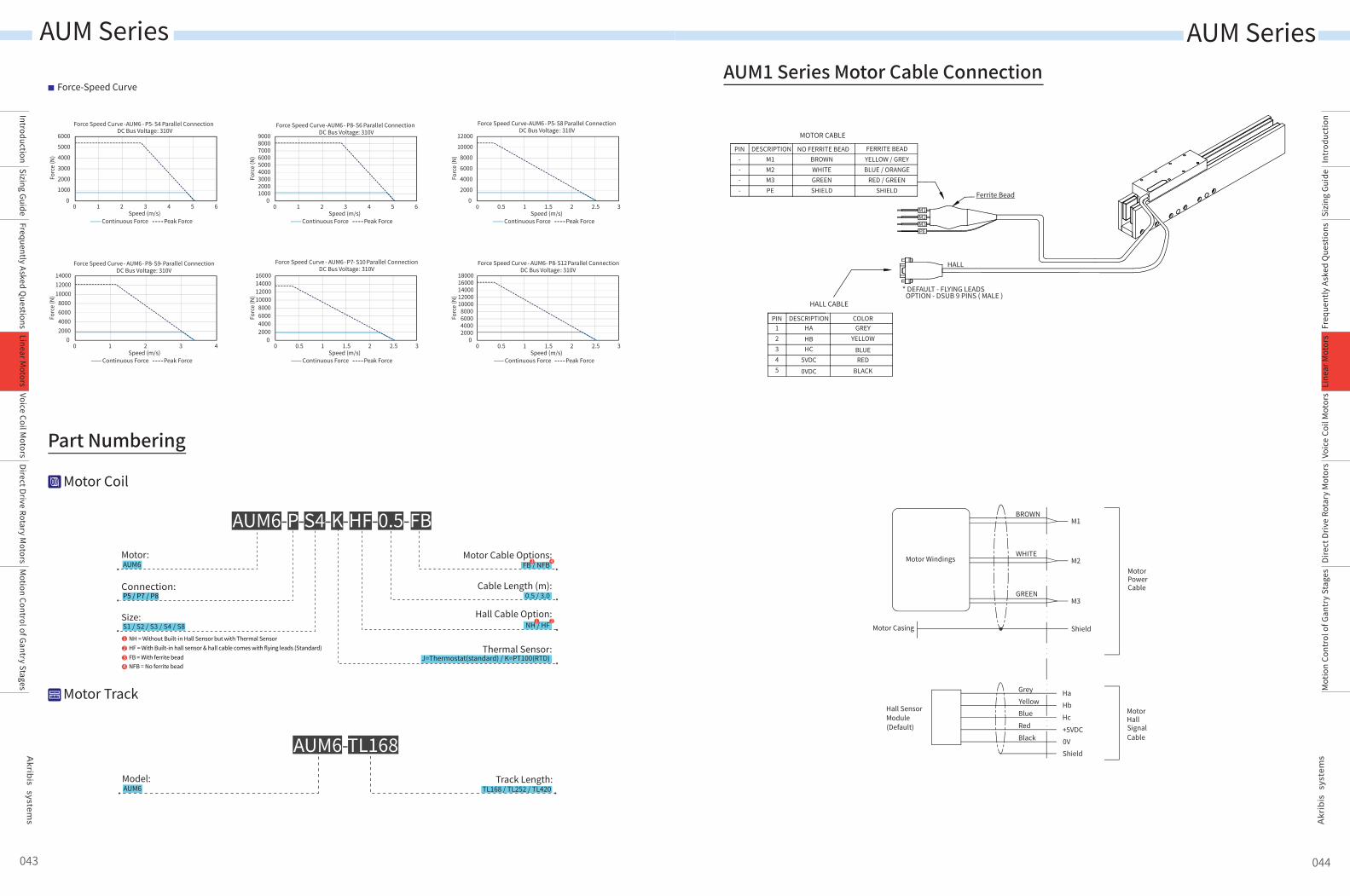
AUM6Motor:
P5 / P7 / P8Connection:
S1 / S2 / S3 / S4 / S8Size:
Cable Length (m):
Thermal Sensor:J=Thermostat(standard) / K=PT100(RTD)
Hall Cable Option:
Motor Cable Options:
AUM6-P-S4-K-HF-0.5-FB M1
M2
M3
Shield
Hall SensorModule(Default)
HaHbHc+5VDC0VShield
GreyYellowBlueRedBlack
MotorHallSignalCable
Motor Casing
MotorPowerCable
BROWN
WHITE
GREEN
Motor Windings
AUM1 Series Motor Cable Connection
NH / HF
123
NH = Without Built-in Hall Sensor but with Thermal SensorHF = With Built-in hall sensor & hall cable comes with flying leads (Standard)FB = With ferrite bead
4 NFB = No ferrite bead
0
1000
2000
3000
4000
5000
6000
0 1 2 3 4 5 6
Forc
e (N
)
Force Speed Curve -AUM6 - P5- S4 Parallel Connection DC Bus Voltage: 310V
Continuous Force Peak ForceSpeed (m/s)
0100020003000400050006000700080009000
0 1 2 3 4 5 6
Forc
e (N
)
Force Speed Curve-AUM6 - P8- S6 Parallel ConnectionDC Bus Voltage: 310V
Continuous Force Peak ForceSpeed (m/s)
0
2000
4000
6000
8000
10000
12000
0 0.5 1 1.5 2 2.5 3
Forc
e (N
)
Force Speed Curve-AUM6 - P5- S8 Parallel ConnectionDC Bus Voltage : 310V
Continuous Force Peak ForceSpeed (m/s)
02000400060008000
100001200014000
0 1 2 3 4
Forc
e (N
)
Force Speed Curve- AUM6- P8- S9- Parallel ConnectionDC Bus Voltage: 310V
Continuous Force Peak ForceSpeed (m/s)
02000400060008000
10000120001400016000
0 0.5 1 1.5 2 2.5 3
Forc
e (N
)
Force Speed Curve - AUM6- P7- S10 Parallel ConnectionDC Bus Voltage: 310V
Continuous Force Peak ForceSpeed (m/s)
02000400060008000
1000012000140001600018000
0 0.5 1 1.5 2 2.5 3
Forc
e (N
)
Force Speed Curve - AUM6- P8- S12 Parallel ConnectionDC Bus Voltage: 310V
Continuous Force Peak ForceSpeed (m/s)
043 044
Motor Coil
Motor Track
AUM6Model: Track Length:
TL168 / TL252 / TL420
AUM6-TL168
0.5 / 3.0
FB / NFB
2
3 4
1
AUM Series AUM Series
IntroductionSizing Guide
Frequently Asked Questions
Voice Coil Motors
Direct Drive Rotary Motors
Motion Control of Gantry Stages
Linear Motors
Intr
oduc
tion
Sizi
ng G
uide
Freq
uent
ly A
sked
Que
stio
nsVo
ice
Coil
Mot
ors
Dire
ct D
rive
Rota
ry M
otor
sM
otio
n Co
ntro
l of G
antr
y St
ages
Line
ar M
otor
s
HALL
MOTOR CABLE
* DEFAULT - FLYING LEADS OPTION - DSUB 9 PINS ( MALE )
HALL CABLE
DESCRIPTIONPIN COLOR12345
DESCRIPTIONPIN NO FERRITE BEAD----
FERRITE BEADYELLOW / GREYBROWN
GREYHAHBHC
5VDC
0VDC
YELLOWBLUERED
BLACK
M1M2M3PE
WHITEGREENSHIELD
BLUE / ORANGERED / GREEN
SHIELD
M1M2M3PE
Ferrite Bead
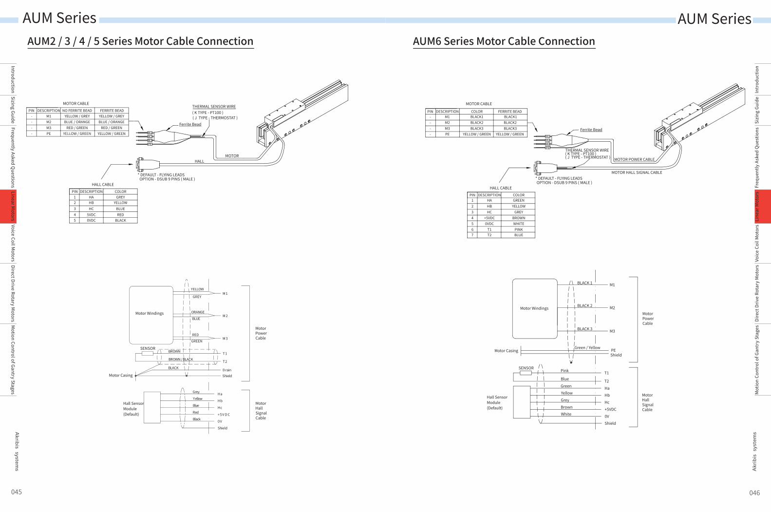
AUM2 / 3 / 4 / 5 Series Motor Cable Connection
M 1
M 2
M 3
Shield
YELLOW
GREY
ORANGE
BLUE
GREEN
RED
T1
T2
BROWN
BROWN / BLACK
D rainBLACK
Ha
Hb
Hc
+5V D C
0V
Shield
Grey
Yellow
Blue
Red
Black
Motor Casing
MotorPowerCable
MotorHallSignalCable
Hall SensorModule(Default)
Motor Windings
SENSOR
045 046
AUM6 Series Motor Cable Connection
AUM Series
IntroductionSizing Guide
Frequently Asked Questions
Voice Coil Motors
Direct Drive Rotary Motors
Motion Control of Gantry Stages
Linear Motors
AUM Series
Intr
oduc
tion
Sizi
ng G
uide
Freq
uent
ly A
sked
Que
stio
nsVo
ice
Coil
Mot
ors
Dire
ct D
rive
Rota
ry M
otor
sM
otio
n Co
ntro
l of G
antr
y St
ages
Line
ar M
otor
s
M1M2M3PE
MOTORHALL
HALL CABLE
* DEFAULT - FLYING LEADS OPTION - DSUB 9 PINS ( MALE )
MOTOR CABLETHERMAL SENSOR WIRE( K TYPE - PT100 )( J TYPE - THERMOSTAT )
DESCRIPTIONPIN NO FERRITE BEAD
DESCRIPTIONPIN COLOR
FERRITE BEADYELLOW / GREYBLUE / ORANGE
RED / GREENYELLOW / GREEN
YELLOW / GREYBLUE / ORANGE
RED / GREENYELLOW / GREEN
Ferrite Bead
M1M2M3PE
----
GREYYELLOW
BLUERED
BLACK
HAHBHC
5VDC0VDC
12345
M1M2M3PE
MOTOR POWER CABLE
MOTOR HALL SIGNAL CABLE
HALL CABLE
* DEFAULT - FLYING LEADS OPTION - DSUB 9 PINS ( MALE )
MOTOR CABLE
THERMAL SENSOR WIRE( K TYPE - PT100 )( J TYPE - THERMOSTAT )
DESCRIPTIONPIN COLOR
DESCRIPTIONPIN COLOR
FERRITE BEADBLACK1BLACK2BLACK3
YELLOW / GREEN
M1M2M3PE
BLACK1BLACK2BLACK3
YELLOW / GREEN
----
HAHBHC
T1T2
+5VDC0VDC
1234567
GREENYELLOW
GREYBROWNWHITEPINKBLUE
Ferrite Bead
M1
M2
M3
Shield
BLACK 1
BLACK 2
BLACK 3
T1
T2
Pink
Blue
SENSOR
Hall SensorModule(Default)
GreenYellowGreyBrownWhite
HaHbHc+5VDC0VShield
Motor Casing
MotorPowerCable
MotorHallSignalCable
Motor Windings
Green / Yellow PE