Embed Size (px)
Citation preview
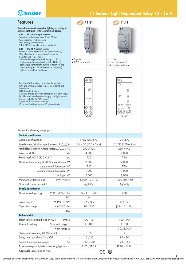
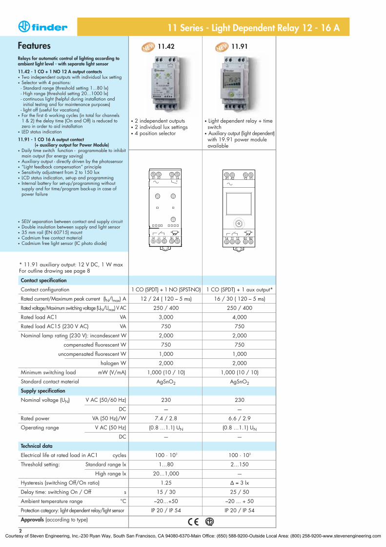
FeaturesRelays for automatic control of lighting according toambient light level - with separate light sensor
11.31 - 1 NO 16 A output contact• Sensitivity adjustment from 1 to 100 lux• One module, 17.5mm wide• Low energy consumption• 24 V DC/AC supply version available
11.41 - 1 CO 16 A output contact• Patented “Zero hysteresis” for energy saving; • “Light feedback compensation” principle• Selector with 4 positions:- Standard range (threshold setting 1...80 lx)- High range (threshold setting 30...1000 lx)- continuous light (helpful during installation and initial testing and for maintenance purposes)
- light off (useful for vacations)
• For the first 3 working cycles the delay time (On and Off) is reduced to zero in order to aid installation
• LED status indication• SELV separation between contact and supply circuit• Double insulation between supply and light sensor• 35 mm rail (EN 60715) mount• Cadmium free contact material• Cadmium free light sensor (IC photo diode)
11.31 11.41
1 NO (SPST-NO) 1 CO (SPDT)
16 / 30 (120 – 5 ms) 16 / 30 (120 – 5 ms)
250 / 400 250 / 400
4,000 4,000
750 750
2,000 2,000
750 750
1,000 1,000
2,000 2,000
1,000 (10 / 10) 1,000 (10 / 10)
AgSnO2 AgSnO2
24 - 110…230 230
24 —
2.5 / 0.9 5.2 / 2
90…260 (0.8 …1.1) UN
— —
100 · 103 100 · 103
1…100 1…80
— 30…1,000
1.25 1
15 / 30 15 / 30
–20…+50 –20…+50
IP 20 / IP 54 IP 20 / IP 54
Contact specification
Contact configuration
Rated current/Maximum peak current (IN/Imax) A
Rated voltage/Maximum switching voltage (UN/Umax) V AC
Rated load AC1 VA
Rated load AC15 (230 V AC) VA
Nominal lamp rating (230 V): incandescent W
compensated fluorescent W
uncompensated fluorescent W
halogen W
Minimum switching load mW (V/mA)
Standard contact material
Supply specification
Nominal voltage (UN) V AC (50/60 Hz)
DC
Rated power VA (50 Hz)/W
Operating range V AC (50 Hz)
DC
Technical data
Electrical life at rated load in AC1 cycles
Threshold setting: Standard range lx
High range lx
Hysteresis (switching Off/On ratio)
Delay time: switching On / Off s
Ambient temperature range °C
Protection category: light dependent relay/light sensor
Approvals (according to type)
• 1 pole• 17.5 mm wide
• 1 pole• “zero hysteresis”• 4 position selector
1
11 Series - Light Dependent Relay 12 - 16 A
For outline drawing see page 8
Courtesy of Steven Engineering, Inc.-230 Ryan Way, South San Francisco, CA 94080-6370-Main Office: (650) 588-9200-Outside Local Area: (800) 258-9200-www.stevenengineering.com
FeaturesRelays for automatic control of lighting according toambient light level - with separate light sensor
11.42 - 1 CO + 1 NO 12 A output contacts• Two independent outputs with individual lux setting• Selector with 4 positions:- Standard range (threshold setting 1...80 lx)- High range (threshold setting 20...1000 lx)- continuous light (helpful during installation and initial testing and for maintenance purposes)
- light off (useful for vacations)• For the first 6 working cycles (in total for channels
1 & 2) the delay time (On and Off) is reduced to zero in order to aid installation
• LED status indication
11.91 - 1 CO 16 A output contact (+ auxiliary output for Power Module)
• Daily time switch function - programmable to inhibit main output (for energy saving)
• Auxiliary output - directly driven by the photosensor• “Light feedback compensation” principle• Sensitivity adjustment from 2 to 150 lux• LCD status indication, set-up and programming• Internal battery for set-up/programming without
supply and for time/program back-up in case of power failure
• SELV separation between contact and supply circuit• Double insulation between supply and light sensor• 35 mm rail (EN 60715) mount• Cadmium free contact material• Cadmium free light sensor (IC photo diode)
11.42 11.91
1 CO (SPDT) + 1 NO (SPST-NO) 1 CO (SPDT) + 1 aux output*
12 / 24 ( 120 – 5 ms) 16 / 30 ( 120 – 5 ms)
250 / 400 250 / 400
3,000 4,000
750 750
2,000 2,000
750 750
1,000 1,000
2,000 2,000
1,000 (10 / 10) 1,000 (10 / 10)
AgSnO2 AgSnO2
230 230
— —
7.4 / 2.8 6.6 / 2.9
(0.8 …1.1) UN (0.8 …1.1) UN
— —
100 · 103 100 · 103
1…80 2…150
20…1,000 —
1.25 Δ = 3 lx
15 / 30 25 / 50
–20…+50 –20 ... + 50
IP 20 / IP 54 IP 20 / IP 54
Contact specification
Contact configuration
Rated current/Maximum peak current (IN/Imax) A
Rated voltage/Maximum switching voltage (UN/Umax) V AC
Rated load AC1 VA
Rated load AC15 (230 V AC) VA
Nominal lamp rating (230 V): incandescent W
compensated fluorescent W
uncompensated fluorescent W
halogen W
Minimum switching load mW (V/mA)
Standard contact material
Supply specification
Nominal voltage (UN) V AC (50/60 Hz)
DC
Rated power VA (50 Hz)/W
Operating range V AC (50 Hz)
DC
Technical data
Electrical life at rated load in AC1 cycles
Threshold setting: Standard range lx
High range lx
Hysteresis (switching Off/On ratio)
Delay time: switching On / Off s
Ambient temperature range °C
Protection category: light dependent relay/light sensor
Approvals (according to type)
• 2 independent outputs• 2 individual lux settings• 4 position selector
• Light dependent relay + time switch
• Auxiliary output (light dependent)with 19.91 power module available
11 Series - Light Dependent Relay 12 - 16 A
* 11.91 auxiliary output: 12 V DC, 1 W maxFor outline drawing see page 8
2Courtesy of Steven Engineering, Inc.-230 Ryan Way, South San Francisco, CA 94080-6370-Main Office: (650) 588-9200-Outside Local Area: (800) 258-9200-www.stevenengineering.com
Technical data
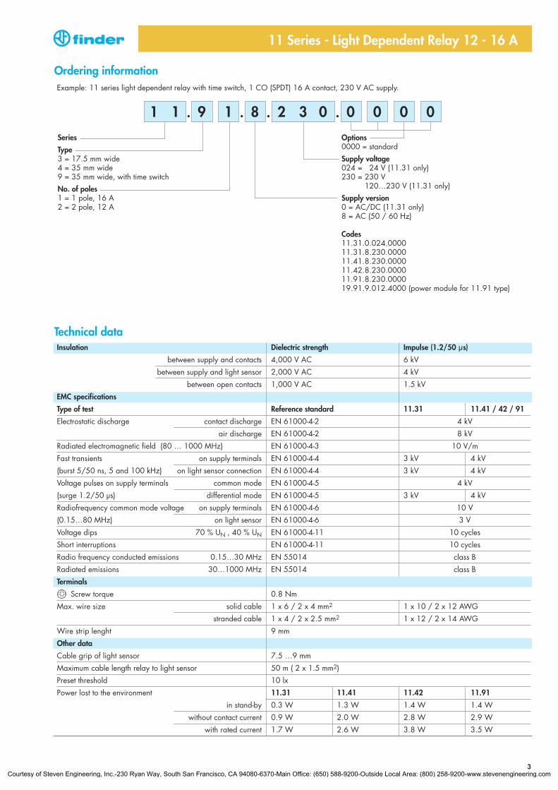
Example: 11 series light dependent relay with time switch, 1 CO (SPDT) 16 A contact, 230 V AC supply.
Options0000 = standard
Supply voltage024 = 24 V (11.31 only)230 = 230 V
120…230 V (11.31 only)
Supply version0 = AC/DC (11.31 only)8 = AC (50 / 60 Hz)
Codes11.31.0.024.000011.31.8.230.000011.41.8.230.000011.42.8.230.000011.91.8.230.000019.91.9.012.4000 (power module for 11.91 type)
Series
Type3 = 17.5 mm wide4 = 35 mm wide9 = 35 mm wide, with time switch
No. of poles1 = 1 pole, 16 A2 = 2 pole, 12 A
9 1 0 08 0 0
Ordering information
. . . .2 3 01 1
11 Series - Light Dependent Relay 12 - 16 A
Insulation Dielectric strength Impulse (1.2/50 µs)
between supply and contacts 4,000 V AC 6 kV
between supply and light sensor 2,000 V AC 4 kV
between open contacts 1,000 V AC 1.5 kV
EMC specifications
Type of test Reference standard 11.31 11.41 / 42 / 91
Electrostatic discharge contact discharge EN 61000-4-2 4 kV
air discharge EN 61000-4-2 8 kV
Radiated electromagnetic field (80 … 1000 MHz) EN 61000-4-3 10 V/m
Fast transients on supply terminals EN 61000-4-4 3 kV 4 kV
(burst 5/50 ns, 5 and 100 kHz) on light sensor connection EN 61000-4-4 3 kV 4 kV
Voltage pulses on supply terminals common mode EN 61000-4-5 4 kV
(surge 1.2/50 µs) differential mode EN 61000-4-5 3 kV 4 kV
Radiofrequency common mode voltage on supply terminals EN 61000-4-6 10 V
(0.15…80 MHz) on light sensor EN 61000-4-6 3 V
Voltage dips 70 % UN , 40 % UN EN 61000-4-11 10 cycles
Short interruptions EN 61000-4-11 10 cycles
Radio frequency conducted emissions 0.15…30 MHz EN 55014 class B
Radiated emissions 30…1000 MHz EN 55014 class B
Terminals
Screw torque 0.8 Nm
Max. wire size solid cable 1 x 6 / 2 x 4 mm2 1 x 10 / 2 x 12 AWG
stranded cable 1 x 4 / 2 x 2.5 mm2 1 x 12 / 2 x 14 AWG
Wire strip lenght 9 mm
Other data
Cable grip of light sensor 7.5 …9 mm
Maximum cable length relay to light sensor 50 m ( 2 x 1.5 mm2)
Preset threshold 10 lx
Power lost to the environment 11.31 11.41 11.42 11.91
in stand-by 0.3 W 1.3 W 1.4 W 1.4 W
without contact current 0.9 W 2.0 W 2.8 W 2.9 W
with rated current 1.7 W 2.6 W 3.8 W 3.5 W
3Courtesy of Steven Engineering, Inc.-230 Ryan Way, South San Francisco, CA 94080-6370-Main Office: (650) 588-9200-Outside Local Area: (800) 258-9200-www.stevenengineering.com
4
011.02
14 11 12 B1 B2
A1 A2 21 24
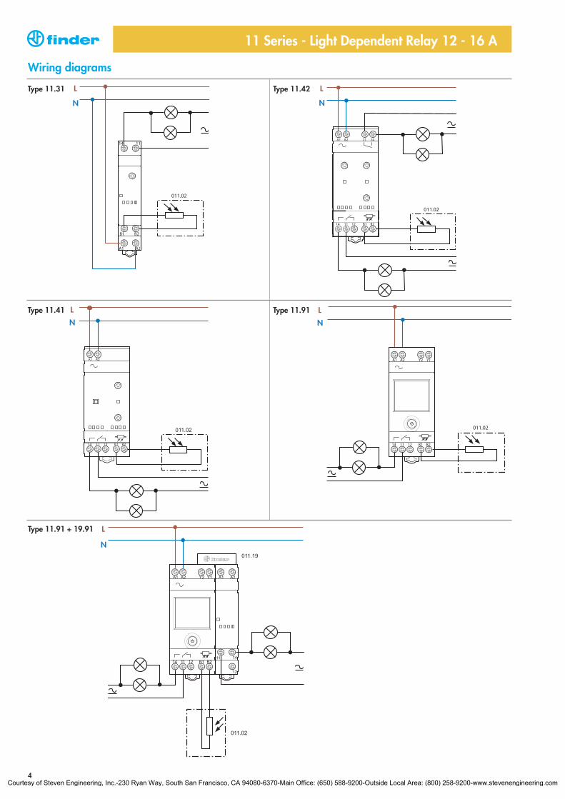
Wiring diagrams
Type 11.31 Type 11.42
Type 11.41 Type 11.91
11 Series - Light Dependent Relay 12 - 16 A
N
L
N
L
N
L
N
L
Type 11.91 + 19.91
N
L
Courtesy of Steven Engineering, Inc.-230 Ryan Way, South San Francisco, CA 94080-6370-Main Office: (650) 588-9200-Outside Local Area: (800) 258-9200-www.stevenengineering.com
5
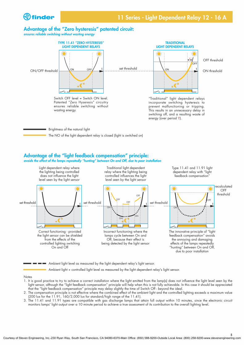
Advantage of the “Zero hysteresis” patented circuit:ensures reliable switching without wasting energy
Switch OFF level = Switch ON level.Patented “Zero Hyseresis” circuitry ensures reliable switching without wasting energy.
“Traditional” light dependent relays incorporate switching hysteresis to prevent malfunctioning or tripping. This results in an unnecessary delay inswitching off, and a resulting waste of energy (over period T).
TYPE 11.41 “ZERO HYSTERESIS”LIGHT DEPENDENT RELAYS
TRADITIONALLIGHT DEPENDENT RELAYS
ON/OFF threshold
OFF threshold
ON thresholdset threshold
11 Series - Light Dependent Relay 12 - 16 A
Brightness of the natural light
The NO of the light dependent relay is closed (light is switched on)
Correct functioning - providedthe light sensor can be shielded
from the effects of the controlled lighting switching
On and Off
Light dependent relay wherethe lighting being controlleddoes not influence the light
level seen by the light sensor
Incorrect functioning where thelamps cycle between On and
Off, because their effect is being detected by the light sensor
Traditional light dependent relay where the lighting beingcontrolled influences the lightlevel seen by the light sensor
The innovative principle of “lightfeedback compensation” avoids
the annoying and damaging effects of the lamps repeatedly“hunting” between On and Off,
due to poor installation
Type 11.41 and 11.91 lightdependent relay with “lightfeedback compensation”
set thresholdset threshold set threshold
recalculatedOFF
threshold
Ambient light level as measured by the light dependent relay's light sensor.
Ambient light + controlled light level as measured by the light dependent relay's light sensor.
Notes1. It is good practice to try to achieve a correct installation where the light emitted from the lamp(s) does not influence the light level seen by the
light sensor, although the “light feedback compensation” principle will help when this is not fully achievable. In this case it should be appreciatedthat the “light feedback compensation” principle may delay slightly the time of Switch Off - beyond the ideal.
2. The compensation principle is not effective where the combined effect of the ambient light and the controlled lighting exceeds a maximum value(200 lux for the 11.91, 160/2,000 lux for standard/high range of the 11.41).
3. The 11.41 and 11.91 types are compatible with gas discharge lamps that attain full output within 10 minutes, since the electronic circuit monitors lamps' light output over a 10 minute period to achieve a true assessment of its contribution to the overall lighting level.
Advantage of the “light feedback compensation” principle:avoids the effect of the lamps repeatedly “hunting” between On and Off, due to poor installation
Courtesy of Steven Engineering, Inc.-230 Ryan Way, South San Francisco, CA 94080-6370-Main Office: (650) 588-9200-Outside Local Area: (800) 258-9200-www.stevenengineering.com
Functions 11.91
11 Series - Light Dependent Relay 12 - 16 A
6
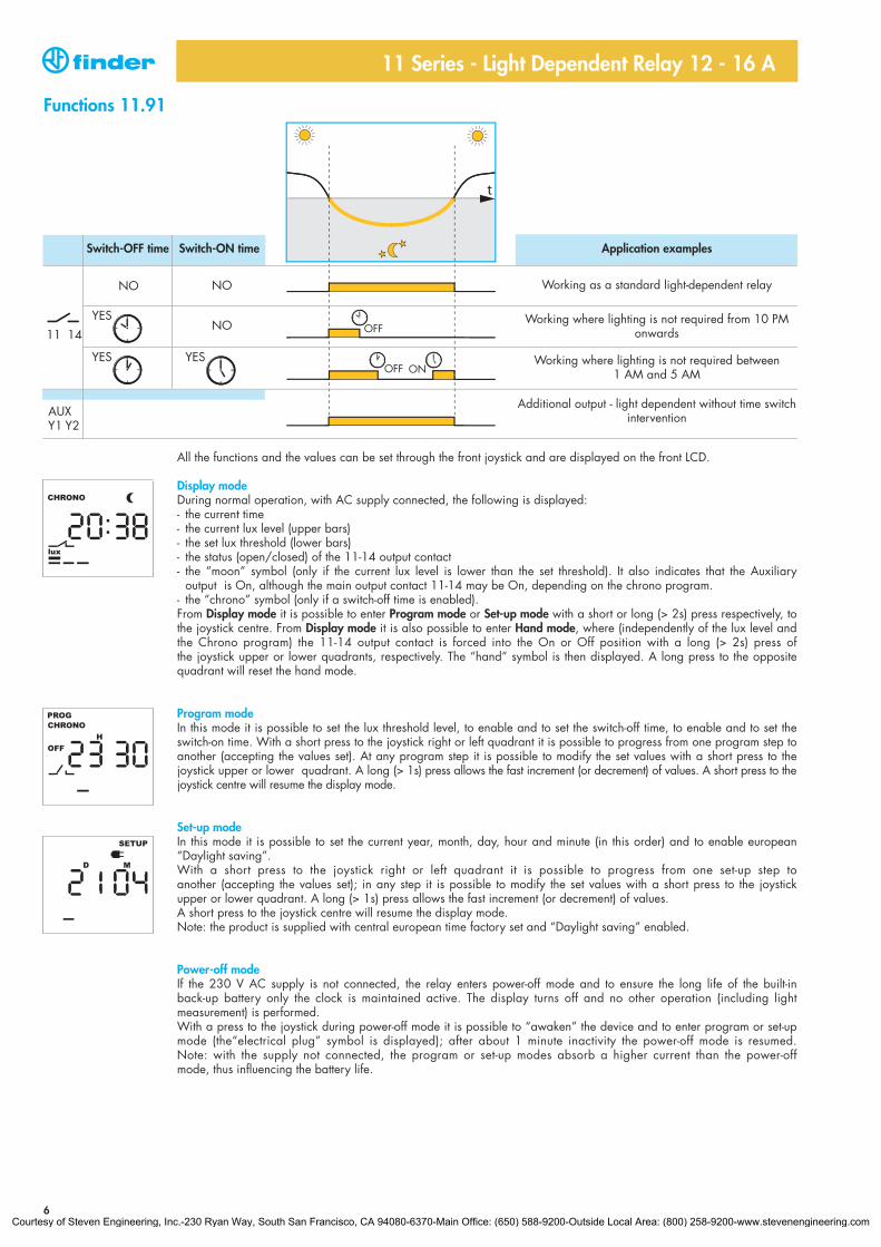
All the functions and the values can be set through the front joystick and are displayed on the front LCD.
Display modeDuring normal operation, with AC supply connected, the following is displayed:- the current time- the current lux level (upper bars)- the set lux threshold (lower bars)- the status (open/closed) of the 11-14 output contact- the “moon” symbol (only if the current lux level is lower than the set threshold). It also indicates that the Auxiliary
output is On, although the main output contact 11-14 may be On, depending on the chrono program.- the “chrono” symbol (only if a switch-off time is enabled).From Display mode it is possible to enter Program mode or Set-up mode with a short or long (> 2s) press respectively, tothe joystick centre. From Display mode it is also possible to enter Hand mode, where (independently of the lux level andthe Chrono program) the 11-14 output contact is forced into the On or Off position with a long (> 2s) press of the joystick upper or lower quadrants, respectively. The “hand” symbol is then displayed. A long press to the opposite quadrant will reset the hand mode.
Program modeIn this mode it is possible to set the lux threshold level, to enable and to set the switch-off time, to enable and to set the switch-on time. With a short press to the joystick right or left quadrant it is possible to progress from one program step toanother (accepting the values set). At any program step it is possible to modify the set values with a short press to the joystick upper or lower quadrant. A long (> 1s) press allows the fast increment (or decrement) of values. A short press to thejoystick centre will resume the display mode.
Set-up modeIn this mode it is possible to set the current year, month, day, hour and minute (in this order) and to enable european “Daylight saving”.With a short press to the joystick right or left quadrant it is possible to progress from one set-up step toanother (accepting the values set); in any step it is possible to modify the set values with a short press to the joystick upper or lower quadrant. A long (> 1s) press allows the fast increment (or decrement) of values.A short press to the joystick centre will resume the display mode.Note: the product is supplied with central european time factory set and “Daylight saving” enabled.
Power-off modeIf the 230 V AC supply is not connected, the relay enters power-off mode and to ensure the long life of the built-in back-up battery only the clock is maintained active. The display turns off and no other operation (including light measurement) is performed. With a press to the joystick during power-off mode it is possible to “awaken” the device and to enter program or set-upmode (the“electrical plug” symbol is displayed); after about 1 minute inactivity the power-off mode is resumed.Note: with the supply not connected, the program or set-up modes absorb a higher current than the power-offmode, thus influencing the battery life.
lux
CHRONO
CHRONOPROG
OFF
SETUP
Switch-OFF time Switch-ON time Application examples
Working as a standard light-dependent relay
Working where lighting is not required from 10 PMonwards
Working where lighting is not required between 1 AM and 5 AM
Additional output - light dependent without time switchintervention
Courtesy of Steven Engineering, Inc.-230 Ryan Way, South San Francisco, CA 94080-6370-Main Office: (650) 588-9200-Outside Local Area: (800) 258-9200-www.stevenengineering.com
11 Series - Light Dependent Relay 12 - 16 A
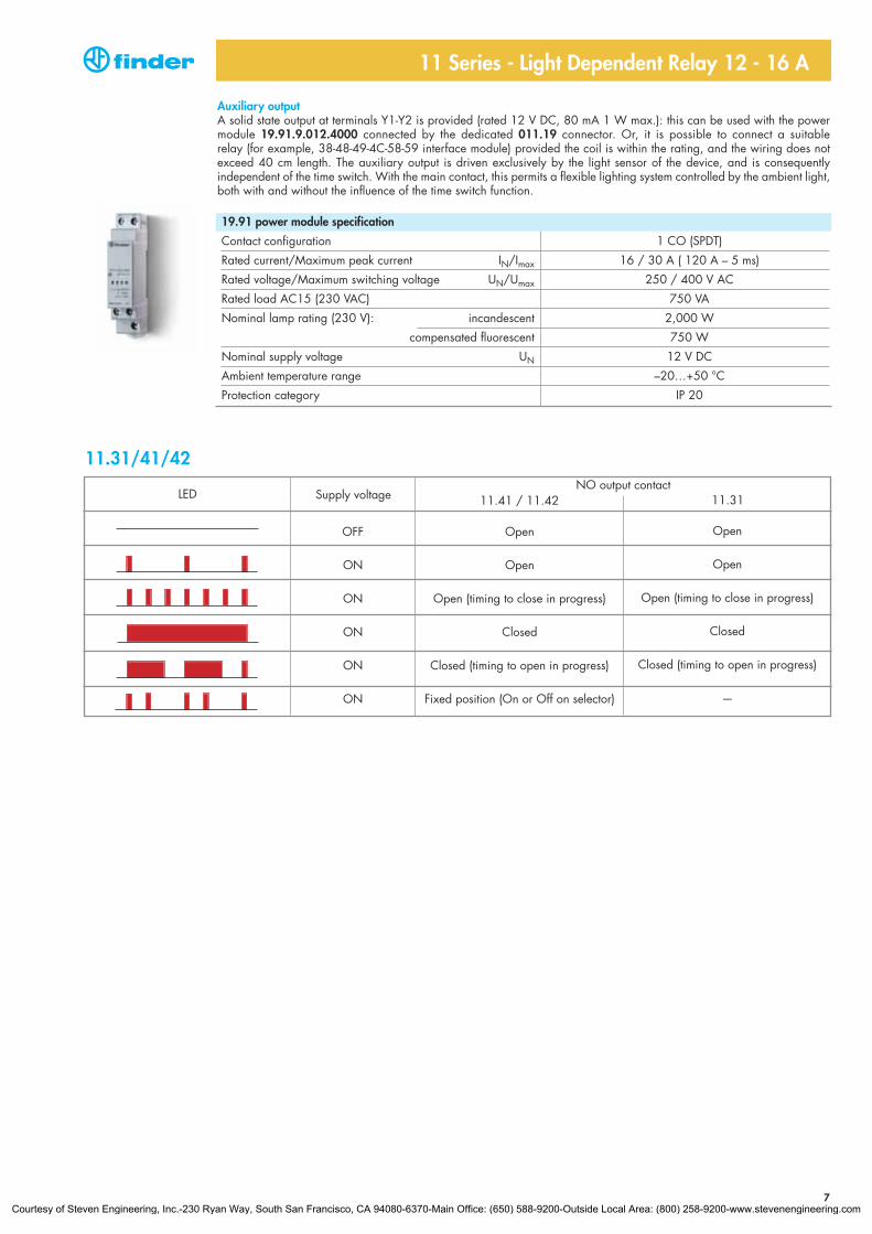
Auxiliary outputA solid state output at terminals Y1-Y2 is provided (rated 12 V DC, 80 mA 1 W max.): this can be used with the powermodule 19.91.9.012.4000 connected by the dedicated 011.19 connector. Or, it is possible to connect a suitable relay (for example, 38-48-49-4C-58-59 interface module) provided the coil is within the rating, and the wiring does notexceed 40 cm length. The auxiliary output is driven exclusively by the light sensor of the device, and is consequently independent of the time switch. With the main contact, this permits a flexible lighting system controlled by the ambient light,both with and without the influence of the time switch function.
19.91 power module specification
Contact configuration 1 CO (SPDT)
Rated current/Maximum peak current IN/Imax 16 / 30 A ( 120 A – 5 ms)
Rated voltage/Maximum switching voltage UN/Umax 250 / 400 V AC
Rated load AC15 (230 VAC) 750 VA
Nominal lamp rating (230 V): incandescent 2,000 W
compensated fluorescent 750 W
Nominal supply voltage UN 12 V DC
Ambient temperature range –20…+50 °C
Protection category IP 20
11.31/41/42NO output contact
Supply voltageLED
OFF
ON
ON
ON
ON
ON
Open
Open
Open (timing to close in progress)
Closed
Closed (timing to open in progress)
Fixed position (On or Off on selector)
Open
Open
Open (timing to close in progress)
Closed
Closed (timing to open in progress)
—
11.41 / 11.42 11.31
7Courtesy of Steven Engineering, Inc.-230 Ryan Way, South San Francisco, CA 94080-6370-Main Office: (650) 588-9200-Outside Local Area: (800) 258-9200-www.stevenengineering.com
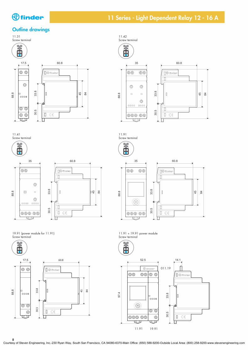
Outline drawings
11 Series - Light Dependent Relay 12 - 16 A
11.31Screw terminal
11.42Screw terminal
11.41Screw terminal
11.91Screw terminal
19.91 (power module for 11.91)Screw terminal
11.91 + 19.91 power moduleScrew terminal
8
11.91
011.19
19.91
Courtesy of Steven Engineering, Inc.-230 Ryan Way, South San Francisco, CA 94080-6370-Main Office: (650) 588-9200-Outside Local Area: (800) 258-9200-www.stevenengineering.com
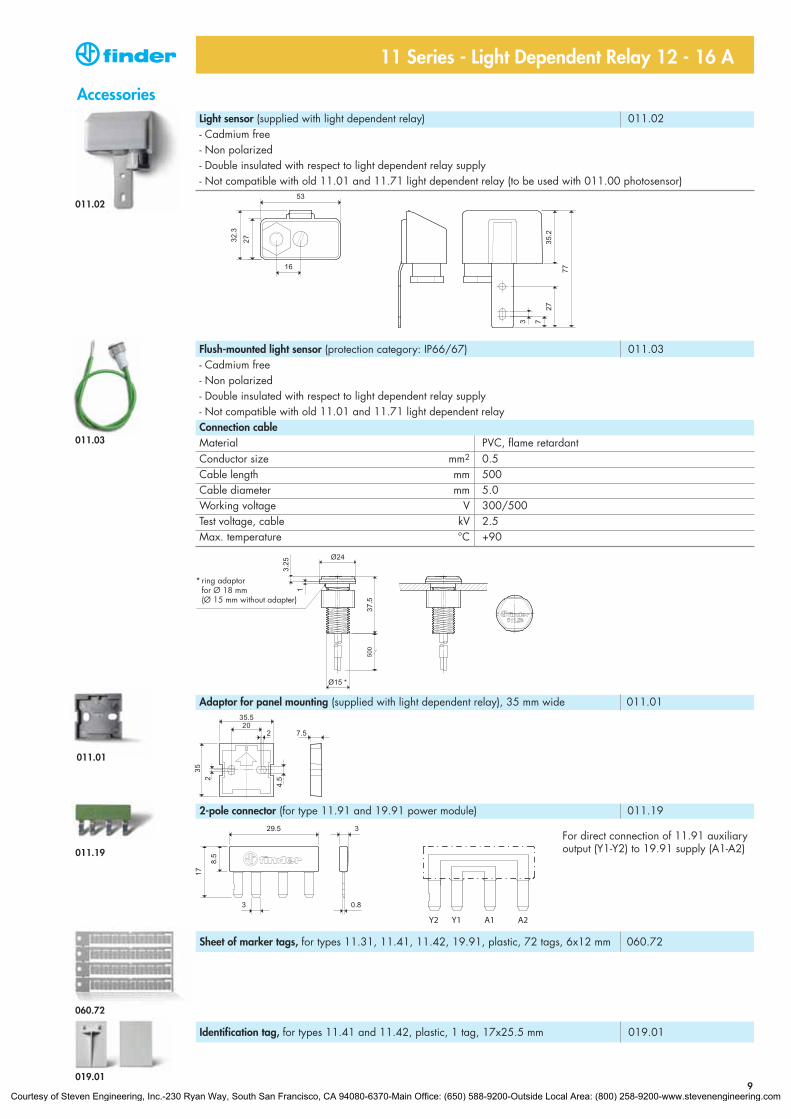
Light sensor (supplied with light dependent relay) 011.02- Cadmium free- Non polarized- Double insulated with respect to light dependent relay supply- Not compatible with old 11.01 and 11.71 light dependent relay (to be used with 011.00 photosensor)
Adaptor for panel mounting (supplied with light dependent relay), 35 mm wide 011.01
011.02
Flush-mounted light sensor (protection category: IP66/67) 011.03- Cadmium free- Non polarized- Double insulated with respect to light dependent relay supply- Not compatible with old 11.01 and 11.71 light dependent relayConnection cableMaterial PVC, flame retardantConductor size mm2 0.5Cable length mm 500Cable diameter mm 5.0Working voltage V 300/500Test voltage, cable kV 2.5Max. temperature °C +90
011.03
011.01
011.19
Accessories
11 Series - Light Dependent Relay 12 - 16 A
9
2-pole connector (for type 11.91 and 19.91 power module) 011.19
Identification tag, for types 11.41 and 11.42, plastic, 1 tag, 17x25.5 mm 019.01
Sheet of marker tags, for types 11.31, 11.41, 11.42, 19.91, plastic, 72 tags, 6x12 mm 060.72
060.72
019.01
For direct connection of 11.91 auxiliaryoutput (Y1-Y2) to 19.91 supply (A1-A2)
* ring adaptor for Ø 18 mm (Ø 15 mm without adapter)
Courtesy of Steven Engineering, Inc.-230 Ryan Way, South San Francisco, CA 94080-6370-Main Office: (650) 588-9200-Outside Local Area: (800) 258-9200-www.stevenengineering.com