Embed Size (px)
Citation preview

11/19/2007 CIS Dept., UMass Dartmouth 1
DRBD: Dynamic Reliability Block Diagram DRBD: Dynamic Reliability Block Diagram
for System Reliability Modelingfor System Reliability Modeling
Prof. Haiping XuConcurrent Software Systems LaboratoryComputer and Information Science DepartmentUniversity of Massachusetts Dartmouth

11/19/2007 CIS Dept., UMass Dartmouth 2
Acknowledgement
Dr. Liudong Xing, Assistant Professor
Electrical and Computer Engineering DepartmentUniversity of Massachusetts Dartmouth
Ryan Robidoux, Graduate Student
Concurrent Software Systems LaboratoryComputer and Information Science DepartmentUniversity of Massachusetts Dartmouth
11/19/2007 CIS Dept., UMass Dartmouth 3
Outline
DRBD controller component blocks Development of DRBD models (example) Formal specifications of DRBD constructs Formal verification of DRBD models Conversion of DRBD models into colored
Petri nets (CPN) Case study: modeling, verification Conclusions and future work
11/19/2007 CIS Dept., UMass Dartmouth 4
A Motivating Example
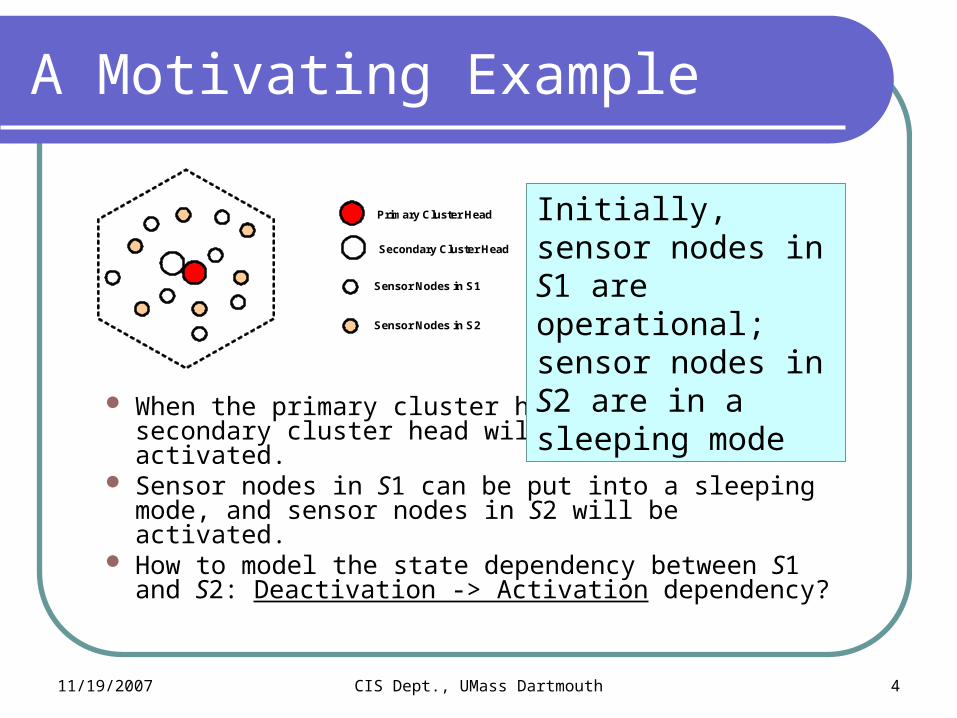
When the primary cluster head fails, the secondary cluster head will be automatically activated.
Sensor nodes in S1 can be put into a sleeping mode, and sensor nodes in S2 will be activated.
How to model the state dependency between S1 and S2: Deactivation -> Activation dependency?
Primary Cluster Head
Sensor Nodes in S1
Sensor Nodes in S2
Secondary Cluster Head
Initially, sensor nodes in S1 are operational; sensor nodes in S2 are in a sleeping mode

11/19/2007 CIS Dept., UMass Dartmouth 5
The State of the Art
Most of the existing reliability modeling tools (e.g., RBD) cannot capture the statestate dependencydependency between components.
Other tools, such as DDynamic FFault TTree (DFT), may support modeling a functional dependency The failure of a component causes some other dependent
components to become inaccessible or unusable However, it still cannot capture the Deactivation -> Activation
state dependency between components. We propose a set of new DDynamic RReliability BBlock
DDiagram (DRBD) constructs as an extension to the existing RBD modeling tool.
11/19/2007 CIS Dept., UMass Dartmouth 6
DRBD Controller Component Blocks
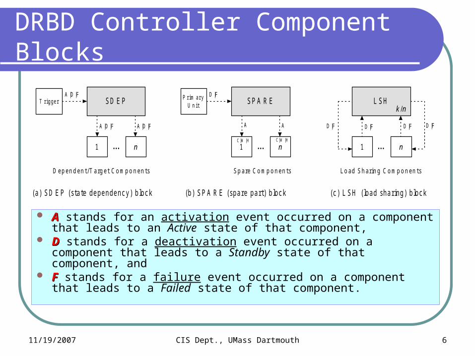
AA stands for an activation event occurred on a component that leads to an Active state of that component,
DD stands for a deactivation event occurred on a component that leads to a Standby state of that component, and
FF stands for a failure event occurred on a component that leads to a Failed state of that component.
T r igge r
A |D |F
1
S D E P
n
A |D |F
A |D |F P r im a r yU n it
A
1
S P A R E
n
A
D |F
D |F
1
L S H
n
D |F
k /n
. . . . . . . . .
D |F D |F
C | W | H C | W | H
D e p e n d e n t /T a rg e t Co mp o n e n t s S p a re Co mp o n e n t s Lo a d S h a rin g Co mp o n e n t s
(a ) S D E P (s ta te de pe nde nc y) b loc k (b) S P A R E (s pa re pa r t) b loc k (c ) L S H ( loa d s ha r ing) b loc k
11/19/2007 CIS Dept., UMass Dartmouth 7
DRBD Model of the WSN Example
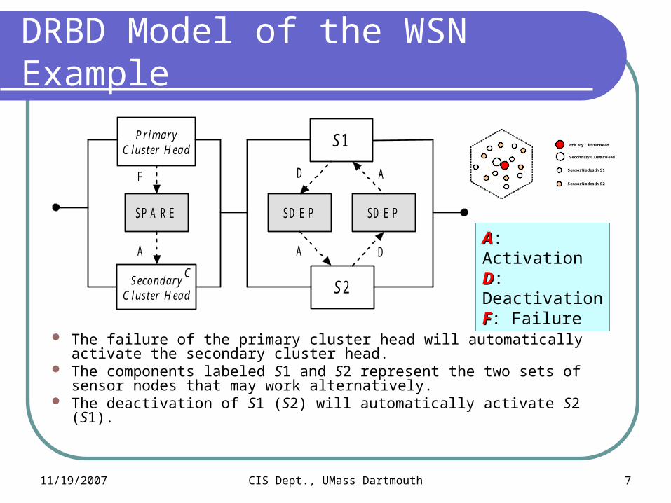
The failure of the primary cluster head will automatically activate the secondary cluster head.
The components labeled S1 and S2 represent the two sets of sensor nodes that may work alternatively.
The deactivation of S1 (S2) will automatically activate S2 (S1).
P rim a ryC lus ter H ea d
Seco nd a ryC lus ter H ead
SP A R E
F
A
S 1
S 2
SD E P SD E P
D
A D
A
C
Primary Cluster Head
Sensor Nodes in S1
Sensor Nodes in S2
Secondary Cluster Head
AA: ActivationDD: DeactivationFF: Failure
11/19/2007 CIS Dept., UMass Dartmouth 8
Formal Specifications
C3
C4
S D E P
C1
C2
S D E PF
FF
DD D
S P A R EA
C
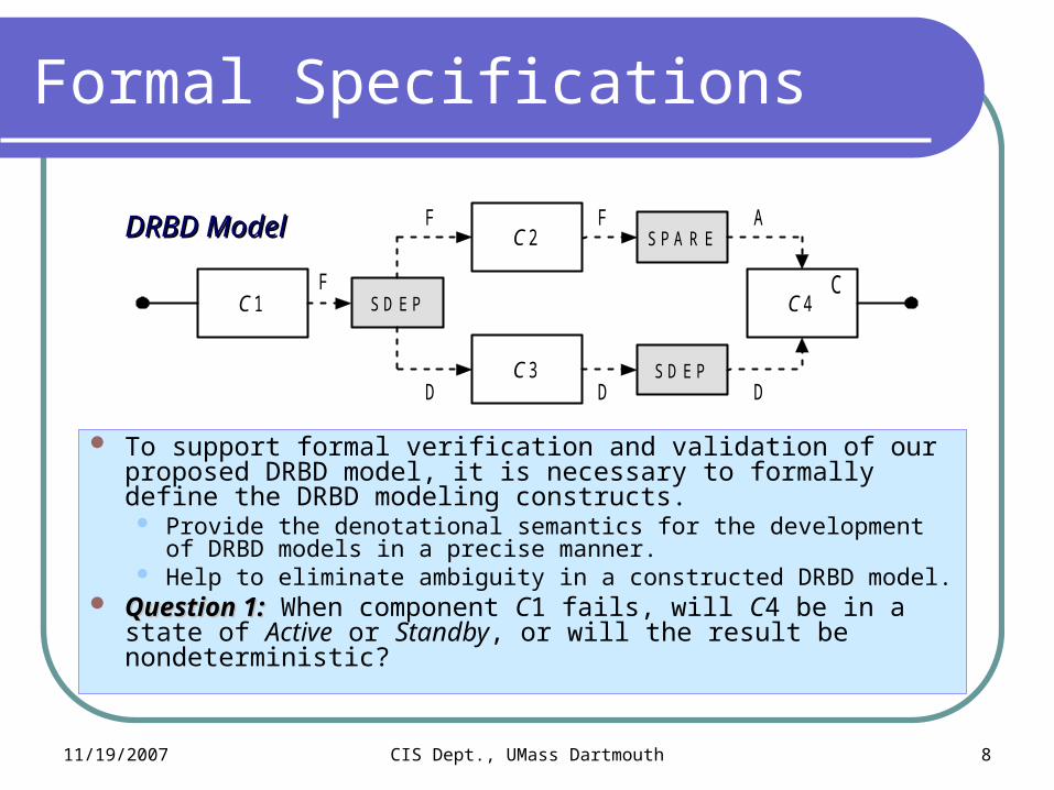
To support formal verification and validation of our proposed DRBD model, it is necessary to formally define the DRBD modeling constructs. Provide the denotational semantics for the development of DRBD
models in a precise manner. Help to eliminate ambiguity in a constructed DRBD model.
Question 1:Question 1: When component C1 fails, will C4 be in a state of Active or Standby, or will the result be nondeterministic?
DRBD ModelDRBD Model
11/19/2007 CIS Dept., UMass Dartmouth 9
Object-Z Specification
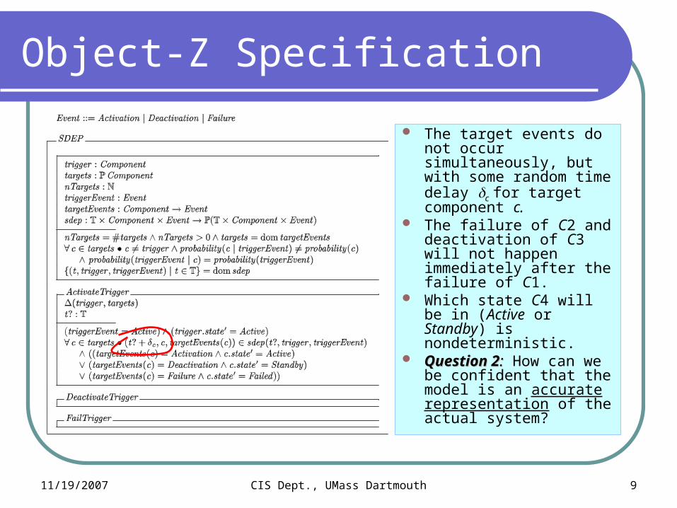
The target events do not occur simultaneously, but with some random time delay c for target component c.
The failure of C2 and deactivation of C3 will not happen immediately after the failure of C1.
Which state C4 will be in (Active or Standby) is nondeterministic.
Question 2Question 2:: How can we be confident that the model is an accurate representation of the actual system?

11/19/2007 CIS Dept., UMass Dartmouth 10
Formal Verification Approach
Testing or simulations are not suitable for verifying DRBD models because it is almost impossible to cover all cases.
Use formal methods (e.g., model checking techniques) to verify the behavioral properties of a DRBD model before the evaluation process starts.
Use temporal logic to specify system properties Property P:Property P: “If component A fails, component B and C will
also fail, which leads to the failure of the whole system S.” The temporal formula in LTL (Linear Temporal Logic) can be
written as []([](AA((BBC)C)<><>S)S) When a DRBD model is proved to be incorrect
Any quantitative evaluation results might be unusable. The DRBD model needs to be fixed.

11/19/2007 CIS Dept., UMass Dartmouth 11
Formal Verification Models
DRBD models are not formally defined & executable. Object-Z specifications of DRBD constructs are formal
specifications, however Are not feasible for verification of behavioral properties. Have no effective analysis and verification tool support.
Convert a DRBD model into a formal executable model such as a state machine or a Petri net model.
We adopt Colored Petri Net (CPN) model because Is user friendly based on its graphical notations. Has powerful, but intuitive rules for defining
structure and dynamic behaviors. Has many existing analysis and verification tools.
CPNCPN
11/19/2007 CIS Dept., UMass Dartmouth 12
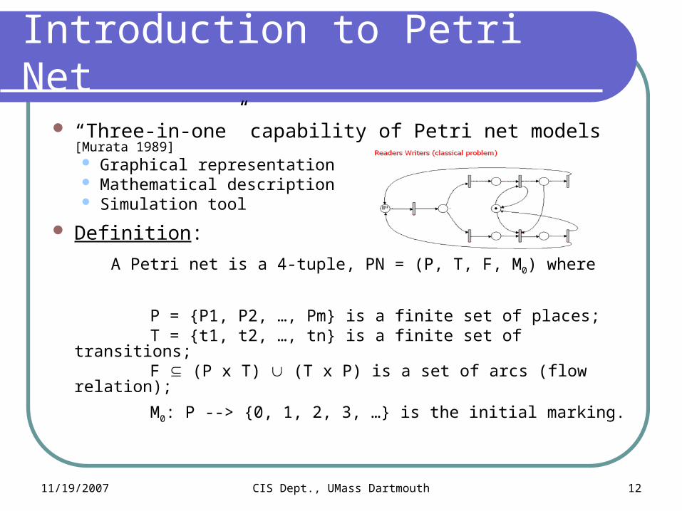
“Three-in-one” capability of Petri net models [Murata 1989] Graphical representation Mathematical description Simulation tool
Definition:
A Petri net is a 4-tuple, PN = (P, T, F, M0) where
P = {P1, P2, …, Pm} is a finite set of places; T = {t1, t2, …, tn} is a finite set of transitions; F (P x T) (T x P) is a set of arcs (flow relation);
M0: P --> {0, 1, 2, 3, …} is the initial marking.
Introduction to Petri Net

11/19/2007 CIS Dept., UMass Dartmouth 13
P4
P2
P5t1
t5
t3
t4
t2P1
P3
An Ordinary Petri Net
In an ordinary Petri net, tokens are all of color black. In a Colored Petri net (CPN or CP-net),
Colors of tokens can represent values. A transition may have a guard and executable code.
11/19/2007 CIS Dept., UMass Dartmouth 14
Convert DBBD into CPN Models
C 1 C 2S P A RECF A
C 1 C 2LS HF F
C 1F D
C 2S D EP2 /2
D |FD |F
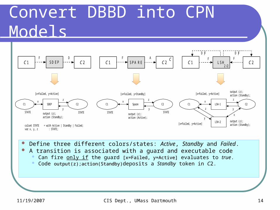
colset STATE = with Active | Standby | Failed;var x, y, z : STATE;
z
y
y
z
x
xx
y
zx
y
z
LSH-2
LSH-1SDEP
[x=Failed, y=Active]
output (z);action (Standby);
Spare
[x=Failed, y=Standby]
output (z); action (Active);
C2C1C2
STATE
C2
STATE
C1
STATE
C1
STATE
[x=Failed, y=Active]output (z);action (Standby);
output (z);action (Standby);[x=Failed, y=Active]
Define three different colors/states: Active, Standby and Failed. A transition is associated with a guard and executable code
Can fire only if the guard [x=Failed, y=Active][x=Failed, y=Active] evaluates to true. Code output(z);action(Standby)output(z);action(Standby)deposits a Standby token in C2.
11/19/2007 CIS Dept., UMass Dartmouth 15
A Case Study
R 1
R 2
S P A R E
C
SD E P
F
D
F
A
C 1
C 2
L SH
D |F
D |F
SD E P
SD E P SD E P
F
F
D
D
D
F
R 1
F
D
C 1
C 2
L SH
D |F
D |F
SD E P
SD E P
F
D
2 /2 2 /2
(a ) L oa d s ha ring s e rve rs c onne c te d to a route r (b) L oa d s ha r ing s e rve rs c onne c te d to a route r w ith a C S P
F
F
F
F
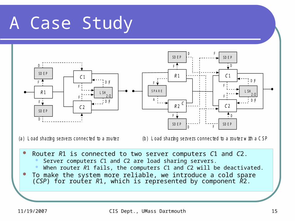
Router R1 is connected to two server computers C1 and C2. Server computers C1 and C2 are load sharing servers. When router R1 fails, the computers C1 and C2 will be deactivated.
To make the system more reliable, we introduce a cold spare (CSP) for router R1, which is represented by component R2.
11/19/2007 CIS Dept., UMass Dartmouth 16
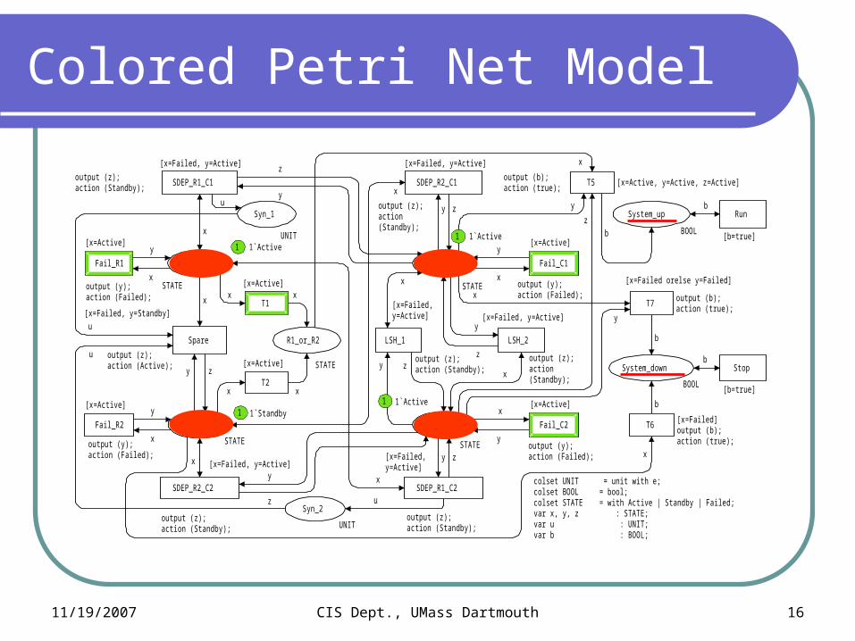
Colored Petri Net Model
colset UNIT = unit with e;colset BOOL = bool;colset STATE = with Active | Standby | Failed;var x, y, z : STATE;var u : UNIT; var b : BOOL;
z
u
u
uy
x
b
z
y
b
x
b
x
x
x
x
x
y
z
xy z
x
x
zy
y
x
y z
x
x
y
b
by
z
x
x
y
x
y y
x
y z
x T7
[x=Failed orelse y=Failed]
output (b);action (true);
T6
T5 [x=Active, y=Active, z=Active]output (b);action (true);
T1
[x=Active]
T2
[x=Active]
LSH_2
[x=Failed, y=Active]
output (z);action (Standby);
LSH_1
[x=Failed, y=Active]
output (z);action (Standby);
SDEP_R1_C2
[x=Failed, y=Active]
output (z);action (Standby);
SDEP_R2_C1
[x=Failed, y=Active]
output (z);action (Standby);
SDEP_R2_C2
[x=Failed, y=Active]
output (z);action (Standby);
Fail_C2
[x=Active]
output (y);action (Failed);
Stop
[b=true]
Run
[b=true]
SDEP_R1_C1
[x=Failed, y=Active]
output (z);action (Standby);
Fail_R2
[x=Active]
output (y);action (Failed);
Fail_R1
[x=Active]
output (y);action (Failed);
Fail_C1
[x=Active]
output (y);action (Failed);
Spare
[x=Failed, y=Standby]
output (z); action (Active);
Syn_2
UNIT
Syn_1
UNIT
R1_or_R2
STATE
C2
1`Active
STATE
System_down
BOOL
C1
1`Active
STATE
System_up
BOOL
R21`Standby
STATE
R1
1`Active
STATE
u
output (b);action (true);
[x=Failed]
1
1
1
1
11/19/2007 CIS Dept., UMass Dartmouth 17
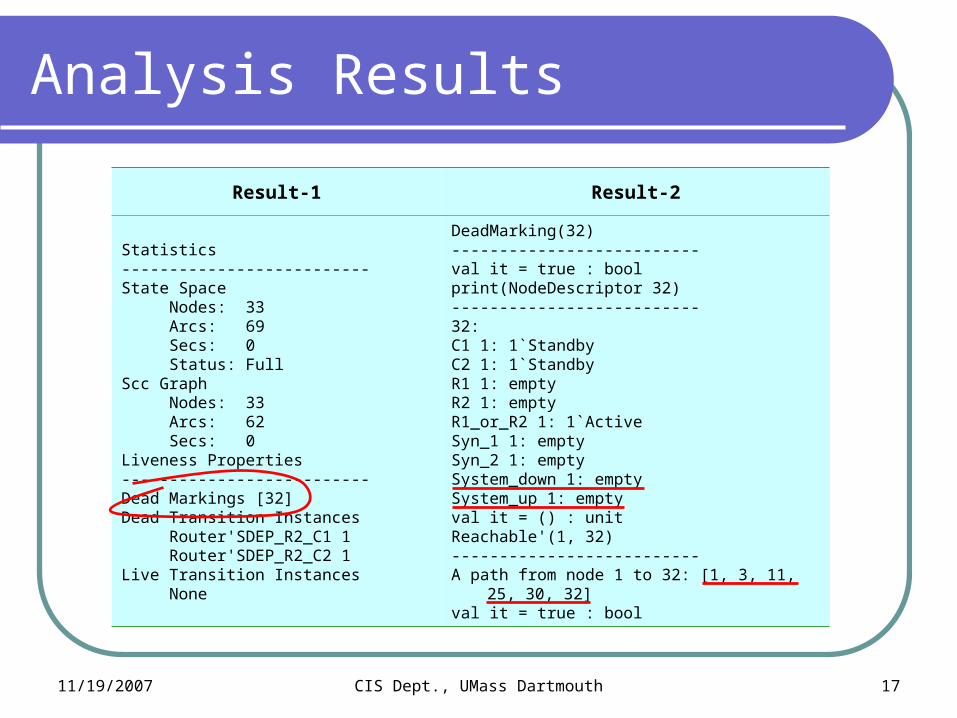
Analysis Results
Result-1 Result-2
Statistics--------------------------State Space Nodes: 33 Arcs: 69 Secs: 0 Status: FullScc Graph Nodes: 33 Arcs: 62 Secs: 0Liveness Properties--------------------------Dead Markings [32]Dead Transition Instances Router'SDEP_R2_C1 1 Router'SDEP_R2_C2 1Live Transition Instances None
DeadMarking(32)--------------------------val it = true : boolprint(NodeDescriptor 32)--------------------------32:C1 1: 1`StandbyC2 1: 1`StandbyR1 1: emptyR2 1: emptyR1_or_R2 1: 1`ActiveSyn_1 1: emptySyn_2 1: emptySystem_down 1: emptySystem_up 1: emptyval it = () : unitReachable'(1, 32)--------------------------A path from node 1 to 32: [1, 3, 11,
25, 30, 32]val it = true : bool
11/19/2007 CIS Dept., UMass Dartmouth 18
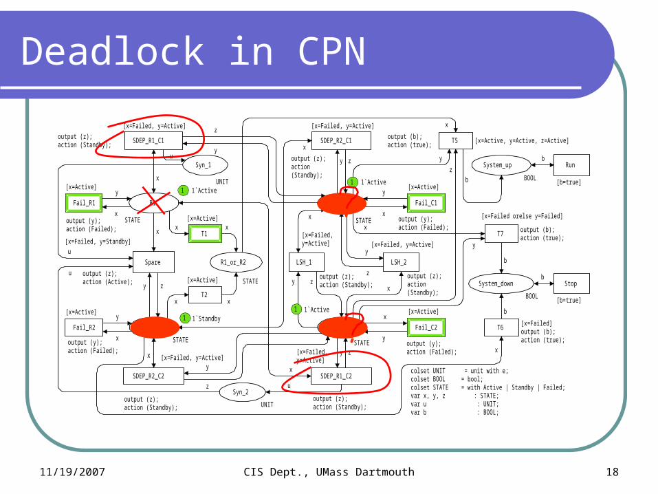
Deadlock in CPN
colset UNIT = unit with e;colset BOOL = bool;colset STATE = with Active | Standby | Failed;var x, y, z : STATE;var u : UNIT; var b : BOOL;
z
u
u
uy
x
b
z
y
b
x
b
x
x
x
x
x
y
z
xy z
x
x
zy
y
x
y z
x
x
y
b
by
z
x
x
y
x
y y
x
y z
x T7
[x=Failed orelse y=Failed]
output (b);action (true);
T6
T5 [x=Active, y=Active, z=Active]output (b);action (true);
T1
[x=Active]
T2
[x=Active]
LSH_2
[x=Failed, y=Active]
output (z);action (Standby);
LSH_1
[x=Failed, y=Active]
output (z);action (Standby);
SDEP_R1_C2
[x=Failed, y=Active]
output (z);action (Standby);
SDEP_R2_C1
[x=Failed, y=Active]
output (z);action (Standby);
SDEP_R2_C2
[x=Failed, y=Active]
output (z);action (Standby);
Fail_C2
[x=Active]
output (y);action (Failed);
Stop
[b=true]
Run
[b=true]
SDEP_R1_C1
[x=Failed, y=Active]
output (z);action (Standby);
Fail_R2
[x=Active]
output (y);action (Failed);
Fail_R1
[x=Active]
output (y);action (Failed);
Fail_C1
[x=Active]
output (y);action (Failed);
Spare
[x=Failed, y=Standby]
output (z); action (Active);
Syn_2
UNIT
Syn_1
UNIT
R1_or_R2
STATE
C2
1`Active
STATE
System_down
BOOL
C1
1`Active
STATE
System_up
BOOL
R21`Standby
STATE
R1
1`Active
STATE
u
output (b);action (true);
[x=Failed]
1
1
1
1
11/19/2007 CIS Dept., UMass Dartmouth 19
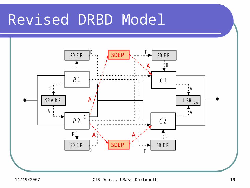
Revised DRBD Model
R 1
R 2
SP A R E
C
SD E P
F
D
F
A
C 1
C 2
L SH
A
A
SD E P
SD E P SD E P
F
F
D
D
D
F
2 /2
SDEP
SDEP
A A
A
A
11/19/2007 CIS Dept., UMass Dartmouth 20
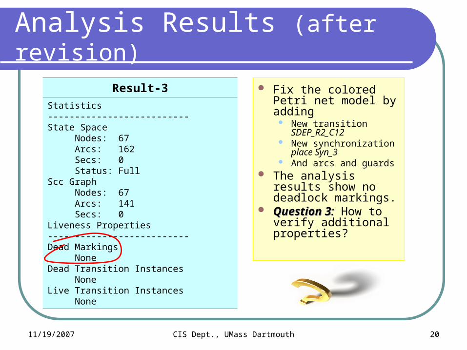
Analysis Results (after revision)
Result-3
Statistics--------------------------State Space Nodes: 67 Arcs: 162 Secs: 0 Status: FullScc Graph Nodes: 67 Arcs: 141 Secs: 0Liveness Properties--------------------------Dead Markings NoneDead Transition Instances NoneLive Transition Instances None
Fix the colored Petri net model by adding
New transition SDEP_R2_C12
New synchronization place Syn_3
And arcs and guards The analysis results
show no deadlock markings.
Question 3Question 3:: How to verify additional properties?

11/19/2007 CIS Dept., UMass Dartmouth 21
Model Checking Results
Formulas ASK-CTL in MLAfterRev
Before Rev
Formula_1val myASKCTLformula = EXIST_UNTIL(TT,NOT(MODAL(TT)));eval_node myASKCTLformula InitNode;
false true
Functionsfun R1_Failed n = (Mark.R1 1 n = 1`Failed);fun R2_Failed n = (Mark.R2 1 n = 1`Failed);fun SystemFailed n = (Mark.System_down 1 n = 1`true);
- -
Formula_2
val isFailed = FORALL_UNTIL(TT, NF("",SystemFailed));val system = OR(NOT(NF("", R2_Failed)), isFailed);val myASKCTLformula = INV(system);eval_node myASKCTLformula InitNode
true true
Formula_3
val isFailed = FORALL_UNTIL(TT, NF("",SystemFailed));val system = OR(NOT(NF("", R1_Failed)), isFailed);val myASKCTLformula = INV(system);eval_node myASKCTLformula InitNode;
false true
11/19/2007 CIS Dept., UMass Dartmouth 22
Conclusions and Future Work
Proposed a new modeling approach called DDynamic RReliability BBlock DDiagrams (DRBD) Resolves the shortcomings of the existing work. Provides a powerful but easy-to-use reliability modeling tool
for complex and large computer-based systems. Supports automated verification of DRBD models.
Develop a software tool that can automatically translate DRBD models into colored Petri nets.
Study efficient evaluation methods for DRBD models. Develop a comprehensive system reliability modeling
tool that supports editing, formal verification, and evaluation of DRBD models.

11/19/2007 CIS Dept., UMass Dartmouth 23
Related Publications
R. Robidoux, H. Xu, and L. Xing Towards Automated Verification of Dynamic Reliability Block Diagrams. To be submitted to journal, Computer and Information Science Dept., UMass Dartmouth, November 2007.
L. Xing, H. Xu, S. V. Amari, and W. Wang A New Framework for Complex System Reliability Analysis: Modeling, Verification, and Evaluation. Submitted to Journal of Autonomic and Trusted Computing (JoATC), September 2007.
H. Xu, L. Xing, and R. Robidoux DRBD: Dynamic Reliability Block Diagrams for System Reliability Modeling. Submitted to International Journal of Computers and Applications (IJCA), August 2007.
H. Xu and L. Xing Formal Semantics and Verification of Dynamic Reliability Block Diagrams for System Reliability Modeling. In Proceedings of the 11th International Conference on Software Engineering and Applications (SEA 2007), November 19-21, 2007, Cambridge, Massachusetts, USA.
Contact Information
Haiping Xu, Assistant Professor Computer and Information Science (CIS) Department, College of EngineeringUniversity of Massachusetts DartmouthPhone : (508) 910-6427Email: [email protected]
Liudong Xing, Assistant Professor Electrical and Computer Engineering (ECE) Department, College of Engineering University of Massachusetts DartmouthPhone : (508) 999-8883Email: [email protected]
11/19/2007 CIS Dept., UMass Dartmouth 24
Questions?
The slides for this talk can be downloaded from
http://www.cis.umassd.edu/~hxu


![[SOLVED] Zimbra on DRBD - Zimbra __ Forums](https://img.pdfslide.net/doc/110x75/54f9cdde4a795956048b45f6/solved-zimbra-on-drbd-zimbra-forums.jpg)
