Embed Size (px)
Citation preview

12 SpeedDrill / Mill Machine
Model 42976 42976 42976 42976 42976
A s s e m b l y & O p e r a t i n g I n s t r u c t i o n s
Copyright 2000 by Harbor Freight Tools®. All Rights Reserved.No portion of this manual or any artwork contained herein may be reproduced in anymanner, shape or form without the express written consent of Harbor Freight Tools.
For technical questions and replacement parts, please call 1-800-444-3353.
www.HarborFreight.com

SPECIFICATIONS
INCLUDED ACCESSORIES
4, 5 and 6mm Hex Wrenches
Drift Pin
Drill Chuck
Chuck Key
Stand Assembly
Precision 0-70O vise
FEATURES1. This machine may be used for surface cutting, drilling, milling, and tapping.2. The high quality of this machine, and its ease of operation makes it suitable for use by students,
amateurs, and home hobbyists, as well as skilled technicians.3. Drilling and milling may be done using hand operated feeding. Milling is done with the quill locked via
Clamp Handle (#83) *.4. Many of the adjustable nuts are bronze, for adjusting thread clearance and reducing wear. These
bronze parts also allow screws to rotate smoothly and improve accuracy.5. The vertical column is very strong and stiff, which makes the machine very stable and improves
accuracy of manufactured parts.6. The machine head is cast steel, and has been heat-treated, stress-relieved, and precision machined.7. Machine gears are precision ground for smooth operation.8. Speeds can be easily changed.9. Thread tapping operations can be done in either rotation, and working depth can be controlled using a
positive stop gauge.
Page 2 SKU # 42976
SAVE THIS MANUAL
You will need the manual for the safety warnings and cautions, assembly instructions, operating procedures,maintenance procedures, trouble shooting, parts list, and diagram. Keep your invoice with this manual.Write the invoice number on the inside of the front cover. Keep both this manual and your invoice in a safe,dry place for future reference.
* For fine adjustment, use a dial test indicator (not included) mounted either to the table or workpiece, andreference a point on the chuck or quill colar that is convenient. Loosen the Clamp Handle (#83) slightly,then tap the chuck feed lever lightly, as you observe the indicator dial.
Motor: 120V/60Hz Single Phase
1/2 HP, 8.5 Amps with Load
12 Speeds (rpm): 300-400-540-720-900-
1040-1500-1740-2100-2260-3100-3840
Motor rpm’s: 1700
Drive Type: V-belt / Pulley
Spindle Taper: MT-2, Diameter: 1.265”
Spindle Stroke: 3-3/8”
Drill Capacity: 5/8”
Face Mill Capacity: 1-1/2”
End Mill Capacity: 5/8”
Max. Chuck to Table: 10”
Column Diameter: 2.830”
Table Slots: 1/2” x 2
Head Rotation: 360O
Net Weight: 470 Lbs.
NOTICEThe Warnings, Cautions, and Instructions discussed in this instruction manual cannotcover all possible conditions and situations that may occur. It must be understood bythe operator that common sense and caution are factors which cannot be built into thisproduct, but must be supplied by the operator.
REV 08/03

SAFETY WARNING & CAUTIONS
READ ALL INSTRUCTIONS BEFORE USING THIS TOOL!
1. KEEP WORK AREA CLEAN. Cluttered areas invite injuries.
2. OBSERVE WORK AREA CONDITIONS. Do not use tools in damp, wet, or poorly lit locations.Don’t expose to rain. Keep work area well lit. Do not use electrically powered equipment in the presenceof flammable gases or liquids.
3. KEEP CHILDREN AWAY. Children must never be allowed in the work area. Do not let them handlemachines, tools, or equipment.
4. STORE IDLE EQUIPMENT. When not in use, tools must be locked up in a dry location to inhibitrust. Always lock up tools and keep out of reach of children.
5. DO NOT FORCE THE TOOL. It will do the job better and more safely at the rate for which it wasintended. Do not use inappropriate attachments in an attempt to exceed the tool’s capacities.
6. USE THE RIGHT TOOL FOR THE JOB. Do not use a tool for a purpose for which it was notintended.
7. DRESS PROPERLY. Do not wear loose clothing or jewelry, as they can be caught in moving parts. Non-skid footwear is recommended. Wear restrictive hair covering to contain long hair. Always wear appropriatework clothing.
8. USE EYE, EAR AND BREATHING PROTECTION. Always wear ANSI approved impact safetygoggles if you are producing metal filings or wood chips. Wear an ANSI approved dust mask orrespirator when working around metal, wood, and chemical dusts and mists. Use ANSI approved earprotection when working in a loud or noisy environment.
9. DO NOT ABUSE THE POWER CORD. Protect the power cord from damage, either from impacts,pulling or corrosive materials. Do not yank machine’s cord to disconnect it from the receptacle.
10. DO NOT OVERREACH. Keep proper footing and balance at all times. Do not reach over or acrossrunning machines.
11. MAINTAIN TOOLS WITH CARE. Keep tools sharp and clean for better and safer performance.Follow instructions for lubricating and changing accessories. Inspect power cord periodically and, ifdamaged, have it repaired by an authorized technician. Inspect all hydraulic seals for leaks prior to use.Control handle and power switch must be kept clean, dry, and free from oil and grease at all times.
12. REMOVE ADJUSTING KEYS AND WRENCHES. Be sure that keys and adjusting wrenches areremoved from the tool or machine work surface before operation.
13. AVOID UNINTENTIONAL STARTING. Be sure that you are prepared to begin work before turning thestart switch on.
Page 3 SKU # 42976

Page 4 SKU # 42976
14. STAY ALERT. Watch what you are doing. Do not operate this machine when you are tired.
15. DO NOT OPERATE THIS MACHINE WHILE UNDER THE INFLUENCE OF ALCOHOL, DRUGS,OR PRESCRIPTION MEDICINES.
16. CHECK FOR DAMAGED PARTS. Before using any tool, any part that appears damaged should becarefully checked to determine that it will operate properly and perform its intended function. Check foralignment and binding of moving parts, any broken parts or mounting fixtures, and any other condition that mayaffect proper operation. Any part that is damaged should be properly repaired or replaced by a qualifiedtechnician. Do not use the tool if any switch does not turn on and off properly.
17. REPLACEMENT PARTS AND ACCESSORIES. When servicing, use only identical replacement partsintended for use with this tool. Replacement parts are available from Harbor Freight Tools. Use of any otherparts will void the warranty.
18. USE THE RIGHT TOOL FOR THE JOB. Do not attempt to force a small tool or attachment to do thework of a larger industrial tool. There are certain applications for which this tool was designed. Do not modifythis tool and do not use this tool for a purpose for which it was not intended.
19. MAINTENANCE. For your own safety,maintenance should be performed regularly by a qualifiedtechnician.
SPECIAL WARNINGS WHEN USING THIS DRILLING / MILLING MACHINEUsing this machine may create special hazards.
Take particular care to safeguard yourself and those around you.
Electrical Safety. Never operate any tool if there is an electrical hazard. Never operate an electricaltool in wet conditions. Never operate a tool with an improper electrical cord or extension cord. Never operatean electrical tool unless you are plugged into a properly grounded outlet, which supplies 110-120 Volts at60 Hz. We recommend you use a circuit which is protected by an appropriate circuit breaker.
Ejected Material. Use safe practices to avoid injury from ejected material. Because milling tools andworkpieces turn at high speed, there is a danger of being injured by materials that may be ejected. Always wearANSI-certified eye protection. Never attempt to machine any item if it is not adequately held. Always stand toone side of the plane in which the materials are spinning, to avoid being hit if an item is ejected. Never allowbystanders to be in the proximity of this machine while in operation.
Entanglement. Use extreme caution to prevent loose materials from being caught in the machine.Never operate this machine with loose clothing, long hair, jewelry, or other items which may become caught inthe tool or workpieces. In case of entanglement, press the OFF switch immediately.
NOTICE: No list of warnings can be all inclusive. The operator must supply commonsense, and operate this tool in a safe manner.

FEATURES AND CONTROLS OF THE #42976 DRILL / MILL MACHINE
Page 5 SKU # 42976
1. Column2. Gear Strip3. Head Crank4. Vertical Head Lock5. Chuck Feed Lever6. Chuck Travel Limit Screw7. Reference Scale8. Chuck Fixing Lever9. Chuck10. Chuck Spindle
11. Chuck Spindle Collar12. Motor13. Drive Belt Cover14. Motor Pulley15. Transfer Pulley16. Drive Pulley17. Drive Belt Tension Lever18. Drive Belt Tension Fixing Bolt19. Head Rotation Control Lever20. Horizontal Control Wheels (2)
8
28
4
13
14
1516
17
18
5
12
1919
20
6
73 2
3
10
11
9
23
25
2022
26
2724
21
26
25
21. Cross Feed Control Wheel22. Butterfly Table Lock Bolts (4)23. T-Slots (2)24. Tray25. Mounting Bolts (4)26. Table Travel Stops (2)27. Table Travel Limiter28. Drive Belt Speed Chart29. Drive Belts (2)
28

Page 6 SKU # 42976
UNPACKING AND INSTALLATION1. Remove protective crating and skids carefully. In the event of damage in transit, contact Harbor Freight
Tools immediately.2. The machine is carefully inspected and tested in operation before it leaves the factory. If any
defects are found on delivery, contact us immediately.3. Read the owner’s manual and become familiar with the parts and controls on the drawings before
using this machine, as familiarity with the controls will enhance your ability and safety in using it.
ASSEMBLY1. After removing the machine from the crate and cleaning it, it must be mounted before use.2. This machine can be mounted directly on a worktable, optional Stand (#42977), or floor.3. The drill chuck must be installed.
INSTALLATION1. It is important that the machine be located on a hard, solid,
level floor, worktable, or optional base, which is capable ofsupporting this heavy machine and the workpieces that areproduced. Find a location that supplies easy access to 120Volt electrical service. Make sure this machine is located in awell lighted and well ventilated area. The floor should beresistant to vibration.
2. Warning: Drill/Mill machines are inherently top heavy.Before moving the machine, be sure the head is fixed on thecolumn. Before moving, lower the head as much as possibleto lower the center of gravity. When moving the machine becareful to keep it balanced; do not allow it to topple over.
3. To set the machine on a solid concrete foundation, it’sadvisable to apply a little grout to touch up any uneveness inthe concrete in order to get a solid foundation at all points.
4. When setting machine on a floor or worktable that has anysurface irregularities, shims should be used to correct thiscondition to the greatest extent possible.
5. There are 4 holes in the base for mounting the machinepermanently to a smooth, solid, and level floor,worktable, or optional stand (#42977).
CLEANING AND LUBRICATION1. Thoroughly clean the machine with a commercial degreaser.
Do not use gasoline, kerosene or other flammable liquids.Avoid getting solvent on rubber parts, or into the electricalcontrols or motor.
2. After cleaning, coat all bright metal with a light lubricant toprevent corrosion.
3. Lubricate all gears and moving parts with a mediumconsistency machine oil.
LEVELING THIS MACHINE1. Before operation, it is critical to level the work table both lengthwise and crosswise, using a precision
level. It will not be possible to maintain accuracy of machined parts if the mill is not properly leveled.
Figure 1. Shown with optional stand.P/N #42977

Page 7 SKU # 42976
EXTENSION CORDS
Note: Performance of this tool may vary depending on variations in local line voltage.Extension cord usage may also affect tool performance.
Your tool has a three-prong plug, therefore you must use a three-prong extension cord. Only userounded jacket extension cords listed by the Underwriters Laboratories (UL). Improper use of extensioncords may cause inefficient operation of your tool which can result in overheating. Be sure your extensioncord is rated to allow sufficient current flow to the motor.
If you are using the tool outdoors, use an extension cord rated for outdoor use (signified by “WA”on the jacket).
The extension cord must have a minimum wire size depending on the amperage of the tool and thelength of the extension cord. This size is determined by its AWG (American Wire Gauge) rating. The smallerthe gauge, the greater the cable’s capacity. The amount of cords used does not matter: Total length determinesthe minimum AWG rating. Every cord must meet the AWG rating. Use the chart below to determine whatAWG rating is required for your situation. Cord length is rated in feet. Harbor Freight Tools can supply ULlisted and outdoor rated cords in most AWG ratings as needed.
AWG RATING CHART
CORD LENGTH 25’ 50’ 75’ 100’ 125’ 150’ 175’ 200’AMPS AWG AWG AWG AWG AWG AWG AWG AWG0-10.0 18 18 16 16 14 14 12 1210.1-13.0 16 16 14 14 14 12 12 1213.1-15 14 14 12 12 12 12 12 —-15-18 14 12 12 12 12 12 —- —-
GROUNDAGE/VOLTAGE WARNING
Common household current is 110-120 volts. As long as the outlet used with the Power TableFeed is rated from 110-120V there will be no complications using it with household receptacles. Plug thetool into a 110-120V properly grounded outlet protected by a 15-amp, dual element time delay or circuitbreaker.
NEVER try to plug a 110-120V tool into a 220-240V circuit or serious complications and possibleinjury to the operator may occur. The plugs have different shapes to prevent this.
This tool has a three-prong plug. The third (round) prong is the ground. Cutting off the ground willresult in a safety hazard and void the warranty.
If the outlet you are planning to use is the two-prong type, do not remove or alter the groundingprong in any manner. Use an adapter and always connect the grounding lug to a known grounding source.It is recommended that you have a qualified electrician replace the two-prong outlet with a properlygrounded three- prong outlet.

Page 8 SKU # 42976
BASIC OPERATIONFor reference numbers mentioned in these instructions, please see page 5.
WARNING: Unplug the drill from its power source before changing bits or attempting any repairs,adjustments or maintenance.
Basic Controls1. Raise and lower the Head by using the Head Crank (#3).2. Feed the Chuck (#9) using the Chuck Feed Lever (#5).
Chuck movement may be limited using the ChuckTravel Limit Screw (#6).
3. Move or feed the Table from side to side using eitherHorizontal Feed Control Wheels (#20).
4. Move the Table front to back using the Cross FeedControl Wheel (#21).
5. Attach workpieces to the Table using jigs or fixtures(not included) or the included precision 70O viseattached to the T-slots (#23).
6. The machine can be turned ON and OFF by usingthe power switch located on the left side of theHead. The upper Switch marked ||||| turns the machineON. The lower switch marked O turns themachine OFF.
WARNING: The machine will continue to run as longas the power cord is plugged in, and the switch isturned ON. Never leave the machine unattended whileit is running.
Installing the ChuckThe Chuck and Chuck Spindle both have a self-centering MT-2 taper.1. Wipe a small amount of grease onto the spindle to prevent corrosion.2. Place the chuck onto the spindle, pressing it upward with a twisting motion. Tap the chuck gently home,
using a soft-faced mallet.3. If desired, fine tune the chuck using a dial indicator. To do this, mount a dial indicator firmly on the table.
Place the dial indicator pointer in contact with the chuck, and adjust the dial to zero. Slowly rotate thechuck and read any out of center on the indicator. Carefully tap the chuck with a mallet upward and tothe side as needed to center the chuck. Continue this process until you are satisfied with the adjustment.
To insert and remove drill or milling bits, use the chuck key provided.1. Insert the Chuck Key into one of the holes in the Chuck, so that it meshes with the cogs on the Chuck.2. Turn the Chuck Key counterclockwise to open the flanges in the Chuck. Continue to turn the Chuck
Key until the opening is large enough to accept the Bit.NOTE: the largest bit size capacity of this Chuck is 5/8” diameter.3. Insert the Drill Bit into the Chuck.4. Turn the Chuck Key clockwise to tighten the jaws around the drill bit shaft. Ensure that the drill bit is
seated securely before starting.5. Remove the Chuck Key, and replace it in its holder before starting.
Figure 2. Drill Head Controls
Preparing for Drilling1. The Chuck (#9) is installed on the Spindle (#10) using a Morris Taper. This is a self-centering design.2. Rotate the Chuck Fixing Lever (#8) counterclockwise to loosen the Spindle for vertical travel.3. You can move the Spindle and Chuck vertically by operating the Chuck Feed Lever (#5).4. Vertical movement of the Chuck and Spindle can be limited by setting the Chuck Travel Limit Screw
(#6). A Reference Scale (#7) indicates the relative travel of the Chuck.5. For drilling blind holes (which do not pass through
the workpiece), set the Chuck Travel Limit Screw(#6). To do so, first determine the desired depth.Then adjust the Limit Screw so that the distance fromthe tip of the drilling bit to the end of the gauge isequal to the desired depth.
6. For drilling holes that pass through the workpiece,loosen the Limit Screw so it does not interfere withthe vertical travel of the spindle.
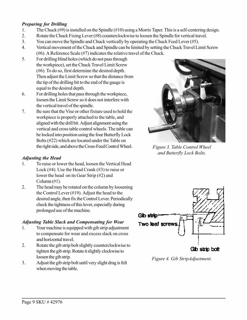
7. Be sure that the Vise or other fixture used to hold theworkpiece is properly attached to the table, andaligned with the drill bit. Adjust alignment using thevertical and cross table control wheels. The table canbe locked into position using the four Butterfly LockBolts (#22) which are located under the Table onthe right side, and above the Cross-Feed Control Wheel.
Adjusting the Head1. To raise or lower the head, loosen the Vertical Head
Lock (#4). Use the Head Crank (#3) to raise orlower the head on its Gear Strip (#2) andColumn (#1).
2. The head may be rotated on the column by looseningthe Control Lever (#19). Adjust the head to thedesired angle, then fix the Control Lever. Periodicallycheck the tightness of this lever, especially duringprolonged use of the machine.
Adjusting Table Slack and Compensating for Wear1. Your machine is equipped with gib strip adjustment
to compensate for wear and excess slack on crossand horizontal travel.
2. Rotate the gib strip bolt slightly counterclockwise totighten the gib strip. Rotate it slightly clockwise toloosen the gib strip.
3. Adjust the gib strip bolt until very slight drag is feltwhen moving the table.
Page 9 SKU # 42976
Figure 4. Gib StripAdjustment.
Figure 3. Table Control Wheeland Butterfly Lock Bolts.

Preparing for Milling1. Loosen the Chuck Travel Limit Screw (#6).2. Install the cutting bit needed to perform the intended milling operation.3. Using the Chuck Feed Lever (#5), adjust the bit to approximately the correct height. Tighten the Chuck
Fixing Lever (#8).4. Set the final vertical adjustment using your milling jig or fixture (not included) or the included 70O
precision vise.5. Set the horizontal adjustment using the Horizontal (#20) or Cross Feed Control Wheels (#21).6. Depending on whether the cut will be made in the X-axis (left or right) or the Y-axis (front to back) one
dimension of the table can be locked into place using one of the two pairs of Butterfly Lock Bolts (#22)located under the Table on the right side or above the Cross Feed Control Wheel.
Moving the Table1. The table can be moved horizontally and front to back by using the Control Wheels.2. If the table is to be moved in one direction only, it can be prevented from moving in the other by
tightening the butterfly bolts under the right side or front of the table. The table can also be locked inboth directions, for example when drilling.
3. The table travel from left to right can also be limited by adjusting the position of the Table Stops (#26).
Changing Machine Speed1. Turn the power off and unplug the power cord.2. To select the proper speed, loosen the Drive Bolt
Tension Fixing Bolt (#18), then loosen the Drive BeltTension Lever (#17).
3. Open the Drive Belt Cover (#13).4. Following the speed chart which is mounted on the
front of the head, position the two drive belts on thepulleys to achieve the desired speed.
5. Tension the belts by moving the Drive Belt TensionLever (#17). Secure the belt tension by tighteningthe Fixing Bolt (#18).
TROUBLE SHOOTING
WARNING! Never perform trouble shooting or maintenance unless the tool is turned OFFand unplugged from its power supply.
The motor overheats, or there is insufficient power.1. The machine is overloaded. Reduce the feed rate, and/or increase the spindle speed.2. The voltage supply is too low. If you have an unreliable power supply, check with a qualified electrician
to repair it.3. The motor carbon brushes may be worn or cracked. Check them and replace if needed.4. There may be a poor electrical connection. Have a qualified electrician check the wiring and power
supply.5. The motor may be burned out. After a long period of heavy use, the motor may burn out. If so, replace
the motor.6. The drill bit or cutting blade may be worn. Sharpen or replace the bits as needed.
Page 10 SKU # 42976
Figure 5. Machine Speed Drive Belt Settings.

The machine doesn’t run when the power switch is turned ON.1. The power cord is not plugged in.2. The chuck spindle may be bound by the workpiece, cutting bit or fixture.3. If there is a surge in the current, the circuit breaker may have opened. Press the circuit breaker back in,
if it is in the open position.4. The belt tension may not be tight. Adjust the tension lever and lock it in place.
The spindle bearing is very hot.1. There is insufficient lubrication. Turn off the power, and check the bearing for lubrication. If necessary,
apply a medium weight bearing grease.2. The spindle bearing is worn, or is fixed too tight. Turn off the power, unplug the electrical connection,
and rotate the spindle by hand. Be sure it turns freely. If not, check the bearing adjustment. If you feeluneveness in the bearing, you will have to replace it.
3. The spindle has been turning at high speed for a long time. After long use, turn the machine off for awhile to give it a rest, and allow it to cool off.
The table travel is not balanced1. The spindle taper gap is too wide. Adjust the arbor bolt properly.2. One of the leaf bolts may be loose. Check and tighten them if necessary.3. The feed is too deep. Reduce the depth of the cut, and make several passes to reach the required depth.4. The gib strip may be out of adjustment. Check it and adjust it if necessary.
There is a vibration,and the cut is not smooth1. The spindle bearing may be improperly adjusted or is worn. Check it and adjust or replace as
necessary.2. The spindle is loose up and down. Check the adjustment of the two inner bearing covers. Adjust them
so there is no free play in the taper bearing, and the bearing turns freely. Tighten them against each otherto save this adjustment.
3. The gap of the taper sliding plate is too wide. Adjust the bolt tension.4. The chuck is loose. Tighten the chuck.5. The drill bit or cutter is dull. Sharpen or replace it. Be sure to use cutting fluid to preserve tool life.6. The workpiece is not held firmly. Check the clamps or vise you are using, and assure that the workpiece
cannot move.
The workpiece is not machined accurately1. A heavy workpiece may be out of balance. Check to see that heavy workpieces are held in balance.
Out of balance pieces may shift when being machined.2. A hammer has been used on the workpiece. Never strike the workpiece with a hammer.3. The table may not be level. Check the table with a spirit level to be sure it is level both side to side and
front to back.4. The machine may not be stable in the floor. Check to be sure the machine is firmly mounted to the floor.
Page 11 SKU # 42976

Page 12 SKU # 42976
PLEASE READ THE FOLLOWING CAREFULLY
THE MANUFACTURER AND/OR DISTRIBUTOR HAS PROVIDED THE PARTS DIAGRAM IN THIS MANUAL ASA REFERENCE TOOL ONLY: NEITHER THE MANUFACTURER NOR DISTRIBUTOR MAKES ANY REPRESENTA-TION OR WARRANTY OF ANY KIND TO THE BUYER THAT HE OR SHE IS QUALIFIED TO MAKE ANY RE-PAIRS TO THE PRODUCT OR THAT HE OR SHE IS QUALIFIED TO REPLACE ANY PARTS OF THE PRODUCT:IN FACT THE MANUFACTURER A ND/OR DISTRIBUTOR EXPRESSLY STATES THATALL REPAIRS ANDPARTS REPLACEMENTS SHOULD BE UNDERTAKEN BY CERTIFIED AND LICENSED TECHNICIANS AND NOTBY THE BUYER. THE BUYER ASSUMES ALL RISK AND LIABILITY ARISING OUT OF HIS OR HER REPAIRS TOTHE ORIGINAL PRODUCT OR REPLACEMENT PARTS THERETO, OR ARISING OUT OF HIS OR HER INSTAL-LATION OF REPLACEMENT PARTS THERETO.
MAINTENANCEAfter each use:1. Turn off the power switch and unplug the machine from its power source.2. Remove any tool bits, clean and lubricate them, and return them to their storage case.3. Using a stiff bristle brush, brush off all chips and shavings left from the machining operation.4. Using a rag, wipe off any excess or dirty oil or cutting fluid left on the machine.5. Lubricate geared, moving and machined metal parts. Apply light grease or oil to all unpainted metal to
prevent corrosion.6. Cover the machine to prevent dust or dirt contamination when not in use.
Daily Maintenance:1. Check the tightness of the mounting bolts holding the head in place.2. If overheating is observed, or unusual noises are produced, stop the machine immediately to check for
lack of lubrication, faulty adjustments, dull tool bits, or other deficiencies. Correct any problems beforeresuming work.
3. Keep the work area clean. If chips or shavings accumulate on the table or fixtures, shut off the powerand clean the chips away with a stiff bristle brush. Re-check the lubrication before continuing.
Weekly Maintenance:1. Clean and coat the lead screws with oil.2. Check the lubrication of the sliding parts of the table. Apply light grease if needed.
Monthly Maintenance:1. Adjust the accuracy of the slides on both the cross and longitudinal feeds.2. Lubricate the bearings, worm gear and worm shaft with light grease.
Yearly Maintenance:1. Adjust the table to assure that it is level in all directions.2. Check the electrical cord, plug, circuit breakers and related connections to assure that they are secure
and safe.
NOTE: Some parts are listed and shown for illustration purposes onlyand are not available individually as replacement parts.

Page 13 SKU # 42976
DRILL / MILL MACHINE, TABLE AND BASE PARTS LISTPlease refer to Parts Diagram on Page 14.
P/N Description Quantity 1 Base (Not Included) 1 2 Door (Not Included) 1 3 Hinge (Not Included) 2 4 Screw (Not Included) 1 5 Oil Tray 1 6 Base 1 7 Screw 4 8 Saddle 1 9 Nut 1 10 Washer 1 11 Screw 1 12 Nut 1 13 Table 1 14 Long Gib 1 15 Adjustment Screw 1 16 Longitudinal Lead Screw 1 17 Support 1 18 Screw 4 19 Ball Bearing 1 20 Scale Ring 1 21 Handle Wheel 1 22 Key 2 23 Washer 1 24 Nut 1 25 Handle Collar 1 26 Handle 1 27 Screw Bracket 2 28 Dog 2 29 Screw 2 30 Support 1 31 Screw 4 32 Ball Bearing 1 33 Scale Ring 1
P/N Description Quantity34 Handle Wheel 1 35 Washer 1 36 Nut 1 37 Handle Collar 1 38 Handle 1 39 Cover 1 40 Screw 3 41 Screw 2 42 Handboard 2 43 Pin 2 44 Crosswise Lead Screw 1 45 Short Gib 1 46 Adjustment Screw 1 47 Ball Bearing 1 48 Support 1 49 Screw 4 50 Ball Bearing 1 51 Scale Ring 1 52 Handle Wheel 1 53 Key 1 54 Nut 1 55 Handle Collar 1 56 Handle 1 57 Support (Rest) 1 58 Screw 4 59 Worm Gear 1 60 Handle 1 61 Pin 1 62 Gear 1 63 Clamp Handle 1 64 Rack 1 65 Column 1 66 Dust Cover 1 67 Screw 1
NOTE: Parts # 1 - 4 represent the optional stand # 42977, which is not included in item # 42976.

Page 14 SKU # 42976
#42976 DRILL / MILL MACHINE, TABLE AND BASE PARTS DIAGRAMPlease refer to Parts List on Page 13.
Note: Parts for optional Stand are shownbut not included with the Drill / Mill machine.

Page 15 SKU # 42976
#42976 DRILL / MILL MACHINE, HEAD PARTS LISTPlease refer to Parts Diagram on Page 16
P/N Description Quantity 68 Body 1 69 Screw 2 70 Shifter Bar 1 71 Pin 1 72 Pin 1 73 Feed Shaft 1 74 Pin 1 75 Scale Ring 1 76 Handle Body 1 77 Scale 1 78 Screw 1 79 Handle Bar 3 80 Knob 3 81 Screw 1 82 Screw 1 83 Clamp Handle 2 84 Spring Seat 1 85 Spring Plate 1 86 Spring Cap 1 87 Screw 1 88 Screw 1 89 Screw 2 90 Switch 1 91 Wire 1 92 Screw 2 93 Rubber Bushing 1 94 Wire Clip 1 95 Shaft 1 96 Pin 1 97 Screw 1 98 Nut 4 99 Washer 4100 Motor Base 1101 Motor 1102 Screw 4103 Motor Pulley 1
P/N Description Quantity104 Headless Set Screw 1105 Nut 1106 Nut 1107 Slide Bar 2108 Pulley Cover 1109 Washer 4110 Screw 4111 V-Belt 1112 Nut 1113 Spindle Pulley 1114 Spring Sleeve 1115 Retaining Ring 1116 Ball Bearing 1117 Collar 1118 Ball Bearing 1119 Retaining Ring 1120 Nut 1121 Washer 1122 Ball Bearing 1123 Sleeve 1124 Ball Bearing 1125 Dust Cover 1126 Spindle 1127 Spindle Bar 1128 Drill Chuck 1129 Wedge Shifter 1130 Key 1131 Center Pulley Shaft 1132 Ball Baring 1133 Collar 1134 Ball Bearing 1135 Retainging Ring 1136 Retainging Ring 1137 Center Pulley 1138 V-Belt 1139 Pulley Cover 1

Page 16 SKU # 42976
#42976 DRILL / MILL MACHINE, HEAD PARTS DIAGRAMPlease refer to Parts List on Page 15.