Embed Size (px)
Citation preview
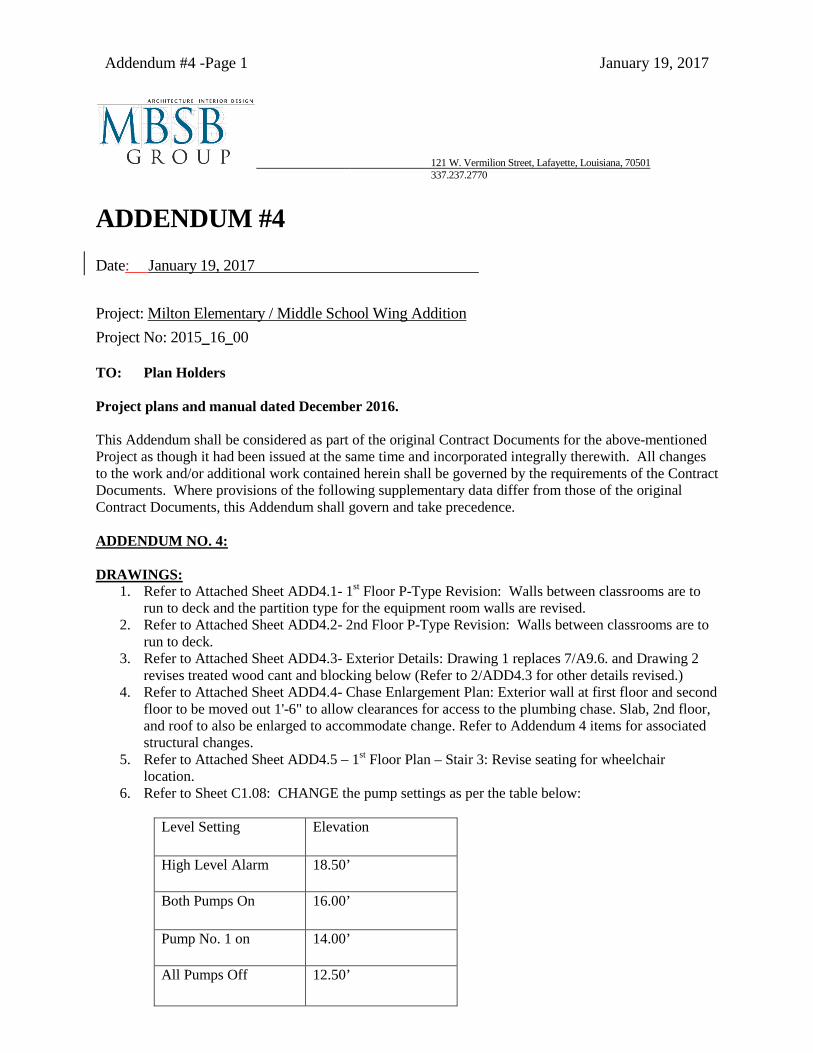
Addendum #4 -Page 1 January 19, 2017
121 W. Vermilion Street, Lafayette, Louisiana, 70501 337.237.2770
ADDENDUM #4 Date: January 19, 2017 Project: Milton Elementary / Middle School Wing Addition Project No: 2015_16_00 TO: Plan Holders Project plans and manual dated December 2016. This Addendum shall be considered as part of the original Contract Documents for the above-mentioned Project as though it had been issued at the same time and incorporated integrally therewith. All changes to the work and/or additional work contained herein shall be governed by the requirements of the Contract Documents. Where provisions of the following supplementary data differ from those of the original Contract Documents, this Addendum shall govern and take precedence. ADDENDUM NO. 4:
DRAWINGS:
1. Refer to Attached Sheet ADD4.1- 1st Floor P-Type Revision: Walls between classrooms are to run to deck and the partition type for the equipment room walls are revised.
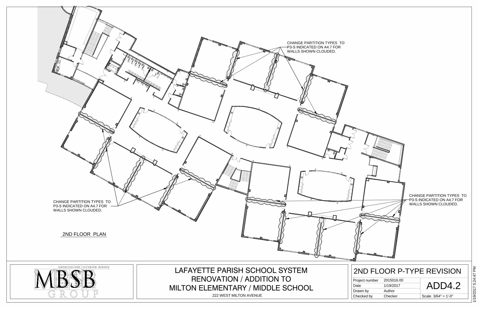
2. Refer to Attached Sheet ADD4.2- 2nd Floor P-Type Revision: Walls between classrooms are to run to deck.
3. Refer to Attached Sheet ADD4.3- Exterior Details: Drawing 1 replaces 7/A9.6. and Drawing 2 revises treated wood cant and blocking below (Refer to 2/ADD4.3 for other details revised.)
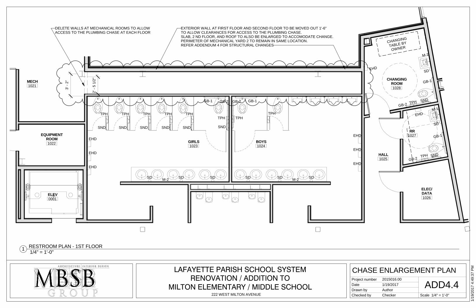
4. Refer to Attached Sheet ADD4.4- Chase Enlargement Plan: Exterior wall at first floor and second floor to be moved out 1'-6" to allow clearances for access to the plumbing chase. Slab, 2nd floor, and roof to also be enlarged to accommodate change. Refer to Addendum 4 items for associated structural changes.
5. Refer to Attached Sheet ADD4.5 – 1st Floor Plan – Stair 3: Revise seating for wheelchair location.
6. Refer to Sheet C1.08: CHANGE the pump settings as per the table below:
Level Setting Elevation
High Level Alarm 18.50’
Both Pumps On 16.00’
Pump No. 1 on 14.00’
All Pumps Off 12.50’
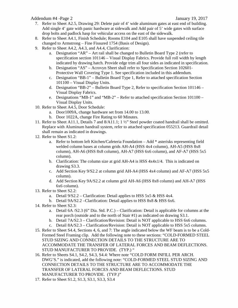
Addendum #4 -Page 2 January 19, 2017 7. Refer to Sheet A2.5, Drawing 29: Delete pair of 4’ wide aluminum gates at east end of building.
Add single 4’ gate with panic hardware at sidewalk and Add pair of 5’ wide gates with surface drop bolts and padlock hasp for vehicular access on the east of the sidewalk.
8. Refer to Sheet A4.1, Finish Schedule; Rooms E104 and E105 shall have suspended ceiling tile changed to Armstrong – Fine Fissured 1754 (Basis of Design).
9. Refer to Sheet A4.2, A4.3, and A4.4, Clarification: a. Designation “AR” – Art rail shall be changed to Bulletin Board Type 2 (refer to
specification section 101146 – Visual Display Fabrics. Provide full roll width by length indicated by drawing hatch. Provide edge trim all four sides as indicated in specification.
b. Designation “AS” – Acrovyn Sheet shall refer to Specification Section 102601- Protective Wall Covering Type 1. See specification included in this addendum.
c. Designation “BB-1” – Bulletin Board Type 1, Refer to attached specification Section 101100 – Visual Display Units.
d. Designation “BB-2” – Bulletin Board Type 2, Refer to specification Section 101146 – Visual Display Fabrics.
e. Designations “MB-1” and “MB-2” – Refer to attached specification Section 101100 – Visual Display Units.
10. Refer to Sheet A4.5, Door Schedule: a. Door1009A, change hardware set from 14.00 to 13.00. b. Door 1022A, change Fire Rating to 60 Minutes.
11. Refer to Sheet A11.1, Details 7 and 8/A11.1; 1 ½” Steel powder coated handrail shall be omitted. Replace with Aluminum handrail system, refer to attached specification 055213. Guardrail detail shall remain as indicated in drawings.
12. Refer to Sheet S1.2: a. Refer to bottom left Kitchen/Cafeteria Foundation – Add * asterisks representing field
welded column bases at column grids AH-A4 (HSS 4x4 column), AH-A5 (HSS 8x8 column), AH-A6 (HSS 8x8 column), AH-A7 (HSS 6x6 column), and AF-A7 (HSS 5x5 column).
b. Clarification: The column size at grid AH-A4 is HSS 4x4x1/4. This is indicated on drawing S3.3.
c. Add Section Key 9/S2.2 at column grid AH-A4 (HSS 4x4 column) and AF-A7 (HSS 5x5 column).
d. Add Section Key 9A/S2.2 at column grid AH-A6 (HSS 8x8 column) and AH-A7 (HSS 6x6 column).
13. Refer to Sheet S2.2: a. Detail 9/S2.2 – Clarification: Detail applies to HSS 5x5 & HSS 4x4. b. Detail 9A/S2.2 –Clarification: Detail applies to HSS 8x8 & HSS 6x6.
14. Refer to Sheet S2.3: a. Detail 6A /S2.3 (6” Dia. Std. P.C.) – Clarification: Detail is applicable for columns at the
rear porch (outside and to the north of Stair #1) as indicated on drawing S3.1. b. Detail 7A/S2.3 – Clarification/Revision: Detail is NOT applicable to HSS 6x6 columns. c. Detail 8A/S2.3 – Clarification/Revision: Detail is NOT applicable to HSS 5x5 columns.
15. Refer to Sheet S4.4, Sections 4, 6, and 7: The angle indicated below the WF beam is to be a Cold-Formed Steel Framing clip. Add the following note to these sections: “COLD-FORMED STEEL STUD SIZING AND CONNECTION DETAILS TO THE STRUCTURE ARE TO ACCOMMODATE THE TRANSFER OF LATERAL FORCES AND BEAM DEFLECTIONS. STUD MANUFACTURER TO PROVIDE. (TYP.) “
16. Refer to Sheets S4.1, S4.2, S4.3, S4.4: Where note “COLD FORM INFILL PER ARCH. DWG’S.” is indicated, add the following note: “COLD-FORMED STEEL STUD SIZING AND CONNECTION DETAILS TO THE STRUCTURE ARE TO ACCOMMODATE THE TRANSFER OF LATERAL FORCES AND BEAM DEFLECTIONS. STUD MANUFACTURER TO PROVIDE. (TYP.)”
17. Refer to Sheet S1.2, S1.3, S3.1, S3.3, S3.4
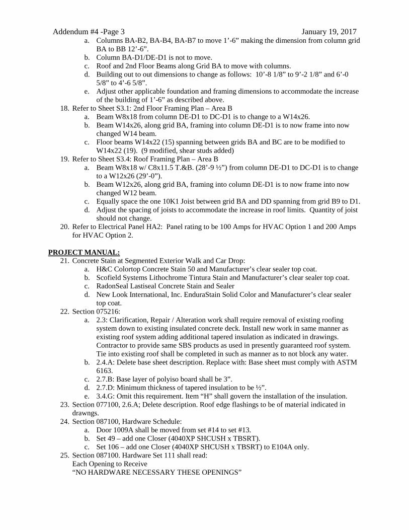
Addendum #4 -Page 3 January 19, 2017 a. Columns BA-B2, BA-B4, BA-B7 to move 1’-6” making the dimension from column grid
BA to BB 12’-6”. b. Column BA-D1/DE-D1 is not to move. c. Roof and 2nd Floor Beams along Grid BA to move with columns. d. Building out to out dimensions to change as follows: 10’-8 1/8” to 9’-2 1/8” and 6’-0
5/8” to 4’-6 5/8”. e. Adjust other applicable foundation and framing dimensions to accommodate the increase
of the building of 1’-6” as described above. 18. Refer to Sheet S3.1: 2nd Floor Framing Plan – Area B
a. Beam W8x18 from column DE-D1 to DC-D1 is to change to a W14x26. b. Beam W14x26, along grid BA, framing into column DE-D1 is to now frame into now
changed W14 beam. c. Floor beams W14x22 (15) spanning between grids BA and BC are to be modified to
W14x22 (19). (9 modified, shear studs added) 19. Refer to Sheet S3.4: Roof Framing Plan – Area B
a. Beam W8x18 w/ C8x11.5 T.&B. (28’-9 ½”) from column DE-D1 to DC-D1 is to change to a W12x26 (29’-0”).
b. Beam W12x26, along grid BA, framing into column DE-D1 is to now frame into now changed W12 beam.
c. Equally space the one 10K1 Joist between grid BA and DD spanning from grid B9 to D1. d. Adjust the spacing of joists to accommodate the increase in roof limits. Quantity of joist
should not change. 20. Refer to Electrical Panel HA2: Panel rating to be 100 Amps for HVAC Option 1 and 200 Amps
for HVAC Option 2.
PROJECT MANUAL: 21. Concrete Stain at Segmented Exterior Walk and Car Drop:
a. H&C Colortop Concrete Stain 50 and Manufacturer’s clear sealer top coat. b. Scofield Systems Lithochrome Tintura Stain and Manufacturer’s clear sealer top coat. c. RadonSeal Lastiseal Concrete Stain and Sealer d. New Look International, Inc. EnduraStain Solid Color and Manufacturer’s clear sealer
top coat. 22. Section 075216:
a. 2.3: Clarification, Repair / Alteration work shall require removal of existing roofing system down to existing insulated concrete deck. Install new work in same manner as existing roof system adding additional tapered insulation as indicated in drawings. Contractor to provide same SBS products as used in presently guaranteed roof system. Tie into existing roof shall be completed in such as manner as to not block any water.
b. 2.4.A: Delete base sheet description. Replace with: Base sheet must comply with ASTM 6163.
c. 2.7.B: Base layer of polyiso board shall be 3”. d. 2.7.D: Minimum thickness of tapered insulation to be ½”. e. 3.4.G: Omit this requirement. Item “H” shall govern the installation of the insulation.
23. Section 077100, 2.6.A; Delete description. Roof edge flashings to be of material indicated in drawngs.
24. Section 087100, Hardware Schedule: a. Door 1009A shall be moved from set #14 to set #13. b. Set 49 – add one Closer (4040XP SHCUSH x TBSRT). c. Set 106 – add one Closer (4040XP SHCUSH x TBSRT) to E104A only.
25. Section 087100. Hardware Set 111 shall read: Each Opening to Receive “NO HARDWARE NECESSARY THESE OPENINGS”
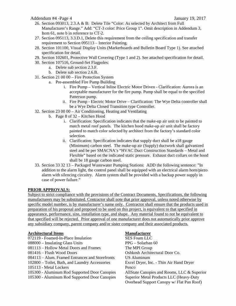
Addendum #4 -Page 4 January 19, 2017 26. Section 093013, 2.3.A & B: Delete Tile “Color: As selected by Architect from Full
Manufacturer’s Range.” Add: “CT-3 color: Price Group 1”. Omit description in Addendum 3, Item 61, note b in reference to CT-2.
27. Section 095113, 3.3.D.1, Delete this requirement from the ceiling specification and transfer requirement to Section 095113 – Interior Painting.
28. Section 101100, Visual Display Units (Markerboards and Bulletin Board Type 1). See attached specification for detail.
29. Section 102601, Protective Wall Covering (Type 1 and 2). See attached specification for detail. 30. Section 107516, Ground-Set Flagpoles:
a. Delete sub section 2.3.F. b. Delete sub section 2.6.B.
31. Section 21 00 00 – Fire Protection System a. Pre-assembled Fire Pump Building
i. Fire Pump – Vertical Inline Electric Motor Driven - Clarification: Aurora is an acceptable manufacturer for the fire pump. Pump shall be equal to the specified Patterson pump.
ii. Fire Pump - Electric Motor Drive – Clarification: The Wye Delta controller shall be a Wye Delta Closed Transition type Controller.
32. Section 23 00 00 – Air Conditioning, Heating and Ventilating b. Page 8 of 32 – Kitchen Hood
i. Clarification: Specification indicates that the make-up air unit to be painted to match metal roof panels. The kitchen hood make-up air unit shall be factory painted to match color selected by architect from the factory’s standard color selection.
ii. Clarification: Specification indicates that supply duct shall be a18 gauge (Minimum) carbon steel. The make-up air (Supply) ductwork shall galvanized steel and be per SMACNA’s “HVAC Duct Construction Standards – Metal and Flexible” based on the indicated static pressure. Exhaust duct collars on the hood shall be 18 gauge carbon steel.
33. Section 33 32 13 – Packaged Wastewater Pumping Stations: ADD the following sentence: ”In addition to the alarm light, the control panel shall be equipped with an electrical alarm horn/piezo alarm with silencing circuitry. Alarm system shall be provided with a backup power supply in case of power failure.”
PRIOR APPROVALS: Subject to strict compliance with the provisions of the Contract Documents, Specifications, the following manufacturers may be substituted. Contractor shall note that prior approval, unless noted otherwise by specific model number, is by manufacturer’s name only. Contractor shall ensure that the products used in preparation of his proposal and proposed to be used on this project, is equivalent to that specified in appearance, performance, size, installation type, and shape. Any material found to not be equivalent to that specified will be rejected. Prior approval of one manufacturer does not automatically prior approve any subsidiary company, parent company and/or sister company and their associated products. Architectural Items Manufacturer 072119 - Foamed-In-Place Insulation SES Foam LLC 088000 – Insulating Glass Units PPG – Solarban 60 081113 – Hollow Metal Doors and Frames The MPI Group 081416 – Flush Wood Doors Oshkosh Architectural Door Co. 084113 – Alum. Framed Entrances and Storefronts US Aluminum 102800 – Toilet, Bath, and Laundry Accessories Excel Dryer, Inc. - Thin Air Hand Dryer 105113 - Metal Lockers Penco 105300 - Aluminum Rod Supported Door Canopies AllState Canopies and Rooms, LLC & Superior 105300 - Aluminum Rod Supported Door Canopies Superior Metal Products LLC (Heavy-Duty
Overhead Support Canopy w/ Flat Pan Roof)
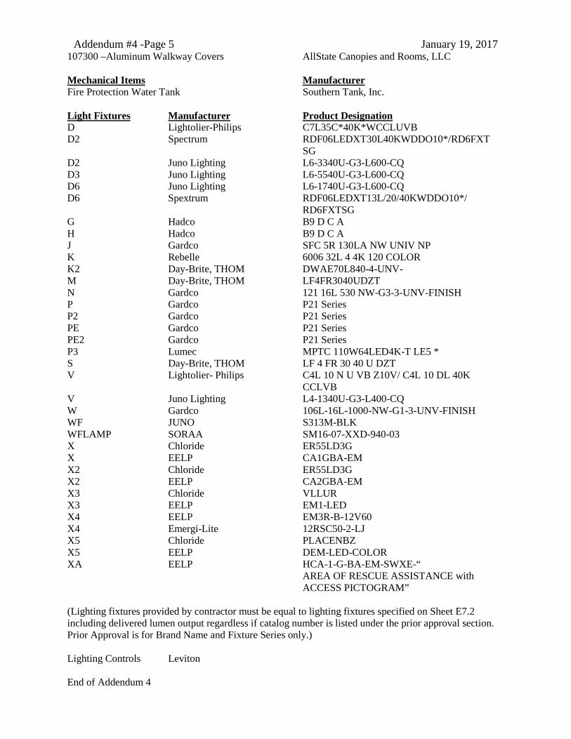
Addendum #4 -Page 5 January 19, 2017 107300 –Aluminum Walkway Covers AllState Canopies and Rooms, LLC Mechanical Items Manufacturer Fire Protection Water Tank Southern Tank, Inc. Light Fixtures Manufacturer Product Designation D Lightolier-Philips C7L35C*40K*WCCLUVB D2 Spectrum RDF06LEDXT30L40KWDDO10*/RD6FXT
SG D2 Juno Lighting L6-3340U-G3-L600-CQ D3 Juno Lighting L6-5540U-G3-L600-CQ D6 Juno Lighting L6-1740U-G3-L600-CQ D6 Spextrum RDF06LEDXT13L/20/40KWDDO10*/
RD6FXTSG G Hadco B9 D C A H Hadco B9 D C A J Gardco SFC 5R 130LA NW UNIV NP K Rebelle 6006 32L 4 4K 120 COLOR K2 Day-Brite, THOM DWAE70L840-4-UNV- M Day-Brite, THOM LF4FR3040UDZT N Gardco 121 16L 530 NW-G3-3-UNV-FINISH P Gardco P21 Series P2 Gardco P21 Series PE Gardco P21 Series PE2 Gardco P21 Series P3 Lumec MPTC 110W64LED4K-T LE5 * S Day-Brite, THOM LF 4 FR 30 40 U DZT V Lightolier- Philips C4L 10 N U VB Z10V/ C4L 10 DL 40K
CCLVB V Juno Lighting L4-1340U-G3-L400-CQ W Gardco 106L-16L-1000-NW-G1-3-UNV-FINISH WF JUNO S313M-BLK WFLAMP SORAA SM16-07-XXD-940-03 X Chloride ER55LD3G X EELP CA1GBA-EM X2 Chloride ER55LD3G X2 EELP CA2GBA-EM X3 Chloride VLLUR X3 EELP EM1-LED X4 EELP EM3R-B-12V60 X4 Emergi-Lite 12RSC50-2-LJ X5 Chloride PLACENBZ X5 EELP DEM-LED-COLOR XA EELP HCA-1-G-BA-EM-SWXE-“
AREA OF RESCUE ASSISTANCE with ACCESS PICTOGRAM”
(Lighting fixtures provided by contractor must be equal to lighting fixtures specified on Sheet E7.2 including delivered lumen output regardless if catalog number is listed under the prior approval section. Prior Approval is for Brand Name and Fixture Series only.) Lighting Controls Leviton
End of Addendum 4
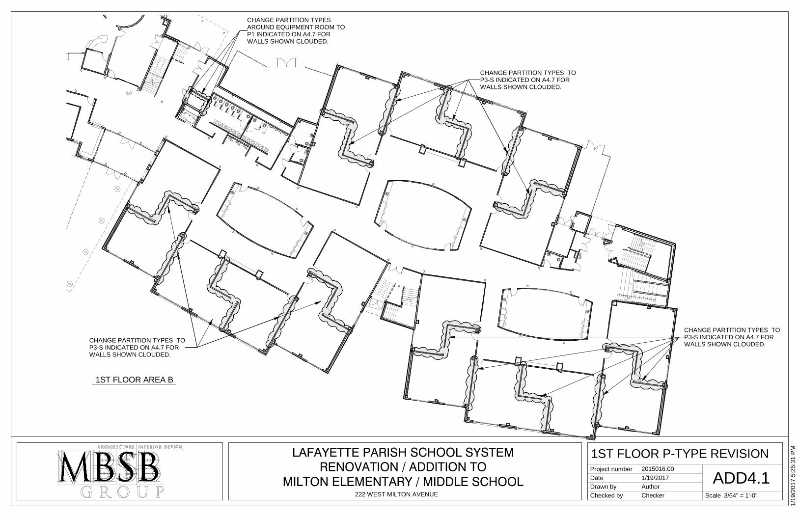
CHANGE PARTITION TYPES AROUND EQUIPMENT ROOM TO P1 INDICATED ON A4.7 FOR WALLS SHOWN CLOUDED.
CHANGE PARTITION TYPES TO P3-S INDICATED ON A4.7 FOR WALLS SHOWN CLOUDED.
CHANGE PARTITION TYPES TO P3-S INDICATED ON A4.7 FOR WALLS SHOWN CLOUDED.
CHANGE PARTITION TYPES TO P3-S INDICATED ON A4.7 FOR WALLS SHOWN CLOUDED.
Scale
Project numberDateDrawn byChecked by
RENOVATION / ADDITION TOMILTON ELEMENTARY / MIDDLE SCHOOL
222 WEST MILTON AVENUE
LAFAYETTE PARISH SCHOOL SYSTEM
3/64" = 1'-0"
1/19
/201
7 5:
25:3
1 PM
ADD4.11ST FLOOR P-TYPE REVISION
2015016.001/19/2017AuthorChecker
1ST FLOOR AREA B
REF
.
CHANGE PARTITION TYPES TO P3-S INDICATED ON A4.7 FOR WALLS SHOWN CLOUDED.
CHANGE PARTITION TYPES TO P3-S INDICATED ON A4.7 FOR WALLS SHOWN CLOUDED.
CHANGE PARTITION TYPES TO P3-S INDICATED ON A4.7 FOR WALLS SHOWN CLOUDED.
Scale
Project numberDateDrawn byChecked by
RENOVATION / ADDITION TOMILTON ELEMENTARY / MIDDLE SCHOOL
222 WEST MILTON AVENUE
LAFAYETTE PARISH SCHOOL SYSTEM
3/64" = 1'-0"
1/19
/201
7 5:
24:4
7 PM
ADD4.22ND FLOOR P-TYPE REVISION
2015016.001/19/2017AuthorChecker
2ND FLOOR PLAN
PREFINISHED METAL WALL PANELS OVER HAT CHANNELS AT 16" O.C.
DAMP PROOFING ON EXTERIOR SHEATHING.
2X WOOD BLOCKING ANCHOR W 16d NAILS AT 6" O.C. STAGGERED
PREFINISHED METAL EDGE W/ INTERMEDIATE BREAK. RE: /8 A9.6
5/8" GYP. BD. ON METAL STUDS. CUT TIGHT TO ANY PENETRATIONS & CAULK ENTIRE PERIMETER.
STEEL BEAM RE: STRUCTURAL
6" STRUCTURAL METAL STUDS AT 16" O.C.
R-19 THERMAL BATT INSULATION
RIGID INSULATION
TAPERED INSULATION. HEIGHT VARIES.
CAP SHEET FULLY ADHERED
2" MIN.
2X WOOD BLOCKING ANCHOR TO STRUCTURE W/ 1/2" THROUGH BOLT AT 16" O.C. COUNTERSINK AS REQ'D FOR ADDITIONAL BLOCKING
RIP 2X AT 45 DEGREE ANGLE ABOVE INSULATION
COVER BOARD
CONTINUOUS METAL CLEAT
FLASHING BASE PLY
BASE PLY FULLY ADHERED -EXTEND DRY DOWN VERTICAL FACE
PRIME METAL FLANGE, SET IN MASTIC & ANCHOR 3" O.C.
5/8" EXTERIOR SHEATHING ON 6" STRUCTURAL METAL STUDS
STEEL TUBE RE: STRUCTURAL
ANCHOR AT 24" O.C. THROUGH SLOTTED HOLES WITH SCREWS & WATERTIGHT WASHERS.
PREFINISHED METAL COPING TAPERED EDGE BOARD
CONTINUOUS METAL CLEAT
2X WOOD BLOCKING ANCHORED TO STRUCTURE
FLASHING MEMBRANE FULLY ADHERED TO SURFACE
TREATED WOOD CANT
BASE FLASHING
COVER BOARD
MODIFIED BITUMEN ROOF SYSTEM & INSULATION AS SPECIFIED.
PREFINISHED METAL END WALL TRIM.
LAP ROOFING FELT OVER & DOWN FRONT EDGE OF PARAPET
STANDING SEAM METAL ROOFING OVER SELF ADHESIVE MEMBRANE.
PLYWOOD BONDED 3" RIGID INSULATION ANCHORED TO METAL DECK
FACTORY FORMED METAL CLOSURE IN SEALANT
TURN UP PANEL AT END
R-19 THERMAL BATT INSULATION
2X TREATED WOOD BLOCKING. RIP TO HEIGHT REQUIRED TO FLUSH OUT WITH COVER BOARD. TYPICAL AT DETAILS 1,3,9,12,15,17,18 & 21/A9.6.
Scale
Project numberDateDrawn byChecked by
RENOVATION / ADDITION TOMILTON ELEMENTARY / MIDDLE SCHOOL
222 WEST MILTON AVENUE
LAFAYETTE PARISH SCHOOL SYSTEM
1 1/2" = 1'-0"
1/19
/201
7 5:
23:4
6 PM
ADD4.3EXTERIOR DETAILS
2015016.001/19/2017AuthorChecker
1 1/2" = 1'-0"1 ROOF EDGE DETAIL(REPLACES 7/A9.6) 1 1/2" = 1'-0"2 PARAPET DETAIL
3' -
2"
GB-1GB-1 GB-2GB-2
TPH TPHTPHTPHTPHTPHTPH TPH
SD SD SD SD SD SDM-2M-2
M-1
SD
EHD
EHD
TPHGB-2
GB-1
SND
CHANGING
TABLE BY
OWNER
GB-2
GB-1
M-1
SD
EHD
EHD
EHD
EHD
EHD
EHD
MECH1021
GIRLS1023
HALL1025
ELEC/DATA1026
ELEV0001
BOYS1024
EQUIPMENTROOM1022
RR1027
CHANGINGROOM1028
TPH SND
SNDSNDSNDSNDSNDSND
2' -
5 1/
2"
Scale
Project numberDateDrawn byChecked by
RENOVATION / ADDITION TOMILTON ELEMENTARY / MIDDLE SCHOOL
222 WEST MILTON AVENUE
LAFAYETTE PARISH SCHOOL SYSTEM
1/4" = 1'-0"
1/19
/201
7 4:
49:3
7 PM
ADD4.4CHASE ENLARGEMENT PLAN
2015016.001/19/2017AuthorChecker
1/4" = 1'-0"1 RESTROOM PLAN - 1ST FLOOR
EXTERIOR WALL AT FIRST FLOOR AND SECOND FLOOR TO BE MOVED OUT 1'-6" TO ALLOW CLEARANCES FOR ACCESS TO THE PLUMBING CHASE.SLAB, 2 ND FLOOR, AND ROOF TO ALSO BE ENLARGED TO ACCOMODATE CHANGE.PERIMETER OF MECHANICAL YARD 2 TO REMAIN IN SAME LOCATION.REFER ADDENDUM 4 FOR STRUCTURAL CHANGES
DELETE WALLS AT MECHANICAL ROOMS TO ALLOW ACCESS TO THE PLUMBING CHASE AT EACH FLOOR
2' -
8"9'
- 10
1/2
"3'
- 0"
5 3/
4"
OMIT SECTION OF RISER AS DIMENSIONED FOR WHEELCHAIR ACCESS. RETURN STAINED CONCRETE TO FLOOR EACH SIDE.
1' - 10"
Scale
Project numberDateDrawn byChecked by
RENOVATION / ADDITION TOMILTON ELEMENTARY / MIDDLE SCHOOL
222 WEST MILTON AVENUE
LAFAYETTE PARISH SCHOOL SYSTEM
1/4" = 1'-0"
1/19
/201
7 5:
23:1
7 PM
ADD4.51ST FLOOR PLAN REVISION
2015016.001/19/2017AuthorChecker
1/4" = 1'-0"1 1ST FLOOR PLAN -STAIR 3
Lafayette Parish School System Milton Elementary / Middle School – Wing Addition and Renovations Addendum 4
PIPE AND TUBE RAILINGS 055213 - 1
SECTION 055213 - PIPE AND TUBE RAILINGS
PART 1 - GENERAL
1.1 RELATED DOCUMENTS
A. Drawings and general provisions of the Contract, including General and Supplementary Conditions and Division 01 Specification Sections, apply to this Section.
1.2 SUMMARY
A. Section Includes: 1. Aluminum pipe railings.
1.3 COORDINATION
A. Coordinate installation of anchorages for railings. Deliver such items to Project site in time for installation.
B. Schedule installation so wall attachments are made only to completed walls. Do not support railings temporarily by any means that do not satisfy structural performance requirements.
1.4 ACTION SUBMITTALS
A. Product Data: For the following:
1. Manufacturer's product lines of mechanically connected railings. 2. Railing brackets.
B. Shop Drawings: Include plans, elevations, sections, details, and attachments to other work.
C. Samples: For each type of exposed finish required.
1. Sections of each distinctly different linear railing member, including handrails, top rails, posts, and balusters.
2. Fittings and brackets. 3. Assembled Sample of railing system, made from full-size components of handrail and
brackets. Sample need not be full height.
a. Show method of connecting members at intersections.
1.5 QUALITY ASSURANCE
A. Welding Qualifications: Qualify procedures and personnel according to the following: 1. AWS D1.2/D1.2M, "Structural Welding Code - Aluminum."
Lafayette Parish School System Milton Elementary / Middle School – Wing Addition and Renovations Addendum 4
PIPE AND TUBE RAILINGS 055213 - 2
1.6 DELIVERY, STORAGE, AND HANDLING
A. Protect mechanical finishes on exposed surfaces from damage by applying a strippable, temporary protective covering before shipping.
1.7 FIELD CONDITIONS
A. Field Measurements: Verify actual locations of walls and other construction contiguous with metal fabrications by field measurements before fabrication.
PART 2 - PRODUCTS
2.1 MANUFACTURERS
A. Aluminum Pipe and Tube Railings: 1. Acceptable manufacturers
a. Blum, Julius & Co. b. Braun, J. G., Company c. Hollaender Manufacturing d. Superior Aluminum Products e. Wagners, R & B, Inc.
B. Source Limitations: Obtain each type of railing from single source from single manufacturer.
2.2 PERFORMANCE REQUIREMENTS
A. Structural Performance: Railings, including attachment to building construction, shall withstand the effects of gravity loads and the following loads and stresses within limits and under conditions indicated:
1. Handrails:
a. Uniform load of 50 lbf/ ft. (0.73 kN/m) applied in any direction. b. Concentrated load of 200 lbf (0.89 kN) applied in any direction. c. Uniform and concentrated loads need not be assumed to act concurrently.
2.3 METALS, GENERAL
A. Metal Surfaces, General: Provide materials with smooth surfaces, without seam marks, roller marks, rolled trade names, stains, discolorations, or blemishes.
B. Brackets, Flanges, and Anchors: Cast or formed metal of same type of material and finish as supported rails unless otherwise indicated.
1. Provide type of bracket with flange tapped for concealed anchorage to threaded hanger bolt or predrilled hole for exposed bolt anchorage and that provides 2-1/4-inch (38-mm) clearance from inside face of handrail to finished wall surface.
Lafayette Parish School System Milton Elementary / Middle School – Wing Addition and Renovations Addendum 4
PIPE AND TUBE RAILINGS 055213 - 3
2.4 ALUMINUM
A. Aluminum, General: Provide alloy and temper recommended by aluminum producer and finisher for type of use and finish indicated, and with not less than the strength and durability properties of alloy and temper designated below for each aluminum form required.
B. Extruded Structural Pipe and Round Tubing: ASTM B 429/B 429M, Alloy 6063-T6.
1. Provide Standard Weight (Schedule 40) pipe unless otherwise indicated.
C. Drawn Seamless Tubing: ASTM B 210 (ASTM B 210M), Alloy 6063-T832.
D. Plate and Sheet: ASTM B 209 (ASTM B 209M), Alloy 6061-T6.
E. Die and Hand Forgings: ASTM B 247 (ASTM B 247M), Alloy 6061-T6.
F. Castings: ASTM B 26/B 26M, Alloy A356.0-T6.
2.5 FASTENERS
A. General: Provide the following: 1. Aluminum Railings: Type 304 stainless-steel fasteners.
B. Fasteners for Anchoring Railings to Other Construction: Select fasteners of type, grade, and class required to produce connections suitable for anchoring railings to other types of construction indicated and capable of withstanding design loads.
C. Fasteners for Interconnecting Railing Components:
1. Provide concealed fasteners for interconnecting railing components and for attaching them to other work, unless otherwise indicated.
2. Provide concealed fasteners for interconnecting railing components and for attaching them to other work, unless exposed fasteners are unavoidable or are the standard fastening method for railings indicated.
3. Provide tamper-resistant flat-head machine screws for exposed fasteners unless otherwise indicated.
2.6 MISCELLANEOUS MATERIALS
A. Welding Rods and Bare Electrodes: Select according to AWS specifications for metal alloy welded.
1. For aluminum railings, provide type and alloy as recommended by producer of metal to be welded and as required for color match, strength, and compatibility in fabricated items.
Lafayette Parish School System Milton Elementary / Middle School – Wing Addition and Renovations Addendum 4
PIPE AND TUBE RAILINGS 055213 - 4
2.7 FABRICATION
A. General: Fabricate railings for flush joint appearance, comply with requirements indicated for design, dimensions, member sizes and spacing, details, finish, and anchorage, but not less than that required to support structural loads.
B. Shop assemble railings to greatest extent possible to minimize field splicing and assembly. Disassemble units only as necessary for shipping and handling limitations. Clearly mark units for reassembly and coordinated installation. Use connections that maintain structural value of joined pieces.
C. Cut, drill, and punch metals cleanly and accurately. Remove burrs and ease edges to a radius of approximately 1/32 inch (1 mm) unless otherwise indicated. Remove sharp or rough areas on exposed surfaces.
D. Form work true to line and level with accurate angles and surfaces.
E. Cut, reinforce, drill, and tap as indicated to receive finish hardware, screws, and similar items.
F. Connections: Fabricate railings with either welded or nonwelded connections unless otherwise indicated.
G. Welded Connections for Aluminum Pipe: Fabricate railings to interconnect members with concealed internal welds that eliminate surface grinding, using manufacturer's standard system of sleeve and socket fittings.
H. Nonwelded Connections: Connect members with concealed mechanical fasteners and fittings. Fabricate members and fittings to produce flush, smooth, rigid, hairline joints.
1. Fabricate splice joints for field connection using an epoxy structural adhesive if this is manufacturer's standard splicing method.
I. Form Changes in Direction as Follows:
1. As detailed. 2. By bending or by inserting prefabricated elbow fittings.
J. For changes in direction made by bending, use jigs to produce uniform curvature for each repetitive configuration required. Maintain cross section of member throughout entire bend without buckling, twisting, cracking, or otherwise deforming exposed surfaces of components.
K. Close exposed ends of railing members with prefabricated end fittings.
L. Provide wall returns at ends of wall-mounted handrails unless otherwise indicated. Close ends of returns unless clearance between end of rail and wall is 1/4 inch (6 mm) or less.
M. Brackets, Flanges, Fittings, and Anchors: Provide wall brackets, flanges, miscellaneous fittings, and anchors to interconnect railing members to other work unless otherwise indicated.
Lafayette Parish School System Milton Elementary / Middle School – Wing Addition and Renovations Addendum 4
PIPE AND TUBE RAILINGS 055213 - 5
1. At brackets and fittings fastened to plaster or gypsum board partitions, provide crush-resistant fillers or other means to transfer loads through wall finishes to structural supports and prevent bracket or fitting rotation and crushing of substrate.
2.8 ALUMINUM FINISHES
A. Appearance of Finished Work: Variations in appearance of abutting or adjacent pieces are acceptable if they are within one-half of the range of approved Samples. Noticeable variations in the same piece are unacceptable. Variations in appearance of other components are acceptable if they are within the range of approved Samples and are assembled or installed to minimize contrast.
B. Mill Finish: AA-M12, nonspecular as fabricated.
PART 3 - EXECUTION
3.1 EXAMINATION
A. Examine gypsum board assemblies, where reinforced to receive anchors, to verify that locations of concealed reinforcements are clearly marked for Installer. Locate reinforcements and mark locations if not already done.
3.2 INSTALLATION, GENERAL
A. Fit exposed connections together to form tight, hairline joints.
B. Perform cutting, drilling, and fitting required for installing railings. Set railings accurately in location, alignment, and elevation; measured from established lines and levels and free of rack.
1. Do not weld, cut, or abrade surfaces of railing components that are coated or finished after fabrication and that are intended for field connection by mechanical or other means without further cutting or fitting.
2. Align rails so variations from level for horizontal members and variations from parallel with rake of steps and ramps for sloping members do not exceed 1/4 inch in 12 feet (6 mm in 3.5 m).
C. Adjust railings before anchoring to ensure matching alignment at abutting joints.
D. Fastening to In-Place Construction: Use anchorage devices and fasteners where necessary for securing railings and for properly transferring loads to in-place construction.
3.3 ATTACHING RAILINGS
A. Anchor railing ends at walls with round flanges anchored to wall construction and connected to railing ends using nonwelded connections.
Lafayette Parish School System Milton Elementary / Middle School – Wing Addition and Renovations Addendum 4
PIPE AND TUBE RAILINGS 055213 - 6
B. Anchor railing ends to metal surfaces with flanges bolted to metal surfaces and connected to railing ends using nonwelded connections.
C. Attach railings to wall with wall brackets, except where end flanges are used. Locate brackets as indicated or, if not indicated, at spacing required to support structural loads.
D. Secure wall brackets and railing end flanges to building construction as follows: 1. For steel-framed partitions, use hanger or lag bolts set into treated wood backing between
studs. Coordinate with stud installation to locate backing members.
3.4 ADJUSTING AND CLEANING
A. Clean aluminum by washing thoroughly with clean water and soap and rinsing with clean water.
3.5 PROTECTION
A. Protect finishes of railings from damage during construction period with temporary protective coverings approved by railing manufacturer. Remove protective coverings at time of Substantial Completion.
END OF SECTION 055213
Lafayette Parish School System Milton Elementary / Middle School – Wing Addition and Renovations Addendum 4
VISUAL DISPLAY UNITS 101100 - 1
SECTION 101100 - VISUAL DISPLAY UNITS
PART 1 - GENERAL
1.1 RELATED DOCUMENTS
A. Drawings and general provisions of the Contract, including General and Supplementary Conditions and Division 01 Specification Sections, apply to this Section.
1.2 SUMMARY
A. Section Includes:
1. Visual display board assemblies.
1.3 ACTION SUBMITTALS
A. Product Data: For each type of product.
1. Include construction details, material descriptions, dimensions of individual components and profiles, finishes, and accessories for visual display units.
B. Shop Drawings: For visual display units.
1. Include plans, elevations, sections, details, and attachment to other work. 2. Show locations of panel joints. Show locations of field-assembled joints for factory-
fabricated units too large to ship in one piece. 3. Include sections of typical trim members.
C. Product Schedule: For visual display units. Use same designations indicated on Drawings.
1.4 INFORMATIONAL SUBMITTALS
A. Product Test Reports: Based on evaluation of comprehensive tests performed by a qualified testing agency, for surface-burning characteristics of tackboards.
B. Sample Warranties: For special warranties.
1.5 CLOSEOUT SUBMITTALS
A. Maintenance Data: For visual display units to include in maintenance manuals.
Lafayette Parish School System Milton Elementary / Middle School – Wing Addition and Renovations Addendum 4
VISUAL DISPLAY UNITS 101100 - 2
1.6 QUALITY ASSURANCE
A. Installer Qualifications: An entity that employs installers and supervisors who are trained and approved by manufacturer.
1.7 DELIVERY, STORAGE, AND HANDLING
A. Deliver factory-fabricated visual display units completely assembled in one piece. If dimensions exceed maximum manufactured unit size, or if unit size is impracticable to ship in one piece, provide two or more pieces with joints in locations indicated on approved Shop Drawings.
1.8 PROJECT CONDITIONS
A. Environmental Limitations: Do not deliver or install visual display units until spaces are enclosed and weathertight, wet-work in spaces is complete and dry, work above ceilings is complete, and temporary HVAC system is operating and maintaining ambient temperature and humidity conditions at occupancy levels during the remainder of the construction period.
B. Field Measurements: Verify actual dimensions of construction contiguous with visual display units by field measurements before fabrication.
1. Allow for trimming and fitting where taking field measurements before fabrication might delay the Work.
1.9 WARRANTY
A. Special Warranty for Porcelain-Enamel Face Sheets: Manufacturer agrees to repair or replace porcelain-enamel face sheets that fail in materials or workmanship within specified warranty period.
1. Failures include, but are not limited to, the following:
a. Surfaces lose original writing and erasing qualities. b. Surfaces exhibit crazing, cracking, or flaking.
2. Warranty Period: 50 years from date of Substantial Completion.
PART 2 - PRODUCTS
2.1 MANUFACTURERS
A. Source Limitations: Obtain each type of visual display unit from single source from single manufacturer.
Lafayette Parish School System Milton Elementary / Middle School – Wing Addition and Renovations Addendum 4
VISUAL DISPLAY UNITS 101100 - 3
2.2 PERFORMANCE REQUIREMENTS
A. Surface-Burning Characteristics: Comply with ASTM E 84; testing by a qualified testing agency. Identify products with appropriate markings of applicable testing agency.
1. Flame-Spread Index: 25 or less. 2. Smoke-Developed Index: 450 or less.
2.3 VISUAL DISPLAY BOARD ASSEMBLY
A. Acceptable manufacturer’s 1. Claridge Products 2. Egan Visual 3. Marsh Industries 4. Nudo Products 5. Or equal products meeting specification
B. Visual Display Board Assembly (Markerboard Type 1): factory fabricated.
1. Assembly: Markerboard, tackboard, or combination unit. 2. Corners: Square. 3. Width: As indicated on Drawings. 4. Height: As indicated on Drawings. 5. Mounting Method: Direct to wall.
C. Markerboard Panel: Porcelain-enamel-faced markerboard panel on core indicated.
1. Color: White.
D. Tackboard Panel (Bulletin Board Type 1): Plastic-impregnated-cork tackboard panel on core indicated.
E. Aluminum Frames and Trim: Fabricated from not less than 0.062-inch- (1.57-mm-) thick, extruded aluminum; Standard size and shape.
1. Field-Applied Trim: Manufacturer's standard, snap-on trim with no visible screws or exposed joints.
2. Aluminum Finish: Clear anodic finish.
F. Combination Assemblies: Provide manufacturer's standard exposed trim between abutting sections of visual display panels.
G. Chalktray: Manufacturer's standard; continuous.
1. Box Type: Extruded aluminum with slanted front, grooved tray, and cast-aluminum end closures.
H. Display Rail: Manufacturer's standard, extruded-aluminum display rail with plastic-impregnated-cork insert, end stops, and continuous paper holder, designed to hold accessories.
Lafayette Parish School System Milton Elementary / Middle School – Wing Addition and Renovations Addendum 4
VISUAL DISPLAY UNITS 101100 - 4
1. Size: 1 inch (25 mm) high by full length of visual display unit indicated on Drawings. 2. Map Hooks: Two map hooks for every 48 inches (1200 mm) of display rail or fraction
thereof. 3. Aluminum Color: Match finish of visual display assembly trim.
I. Paper Holder Display Rail: Extruded aluminum; designed to hold paper by clamping action.
J. Curved Markerboard panel (Markerboard Type 2 – noted at interior elevations 9 and 10/A7.2): 1. Porcelain-Enamel sheet, 24 gauge steel sheet, white finish. 2. Single piece, no splicing. 3. Adhesive: Manufacturer’s recommended standard contact cement. 4. Border Frame: Aluminum “J” trim.
Products: Subject to compliance with requirements, provide one of the following; a. Korogard J208/J212 with pre-formed corners. b. Korogard H208 H Divider for TacWall
2.4 TACKBOARD PANELS
A. Tackboard Panels:
1. Facing: 1/8-inch- (3-mm-) thick plastic-impregnated cork. 2. Core: 7/16-inch- (11-mm-) thick fiberboard.
2.5 MATERIALS
A. Porcelain-Enamel Face Sheet: PEI-1002, with face sheet manufacturer's standard two- or three-coat process.
B. Plastic-Impregnated-Cork Sheet: Seamless, homogeneous, self-sealing sheet consisting of granulated cork, linseed oil, resin binders, and dry pigments that are mixed and calendared onto fabric backing; with washable vinyl finish and integral color throughout with surface-burning characteristics indicated.
C. Medium-Density Fiberboard: ANSI A208.2, Grade 130.
D. Extruded Aluminum: ASTM B 221 (ASTM B 221M), Alloy 6063.
E. Adhesives for Field Application: Mildew-resistant, nonstaining adhesive for use with specific type of panels, sheets, or assemblies; and for substrate application; as recommended in writing by visual display unit manufacturer.
2.6 GENERAL FINISH REQUIREMENTS
A. Protect mechanical finishes on exposed surfaces from damage by applying a strippable, temporary protective covering before shipping.
Lafayette Parish School System Milton Elementary / Middle School – Wing Addition and Renovations Addendum 4
VISUAL DISPLAY UNITS 101100 - 5
B. Appearance of Finished Work: Noticeable variations in same piece are unacceptable. Variations in appearance of adjoining components are acceptable if they are within the range of approved Samples and are assembled or installed to minimize contrast.
2.7 ALUMINUM FINISHES
A. Clear Anodic Finish: AAMA 611, AA-M12C22A31, Class II, 0.010 mm or thicker.
PART 3 - EXECUTION
3.1 EXAMINATION
A. Examine substrates and conditions, with Installer present, for compliance with requirements for installation tolerances, surface conditions of wall, and other conditions affecting performance of the Work.
B. Examine walls and partitions for proper preparation and backing for visual display units.
C. Proceed with installation only after unsatisfactory conditions have been corrected.
3.2 PREPARATION
A. Comply with manufacturer's written instructions for surface preparation.
B. Clean substrates of substances, such as dirt, mold, and mildew, that could impair the performance of and affect the smooth, finished surfaces of visual display boards.
C. Prepare surfaces to achieve a smooth, dry, clean surface free of flaking, unsound coatings, cracks, defects, projections, depressions, and substances that will impair bond between visual display units and wall surfaces.
D. Prime wall surfaces indicated to receive direct-applied visual display assemblies and as recommended in writing by primer/sealer manufacturer and visual display unit manufacturer.
3.3 INSTALLATION
A. General: Install visual display surfaces in locations and at mounting heights indicated on Drawings, or if not indicated, at heights indicated below. Keep perimeter lines straight, level, and plumb. Provide grounds, clips, backing materials, adhesives, brackets, anchors, trim, and accessories necessary for complete installation.
B. Field-Assembled Visual Display Board Assemblies (marker board sheet applied to curved wall): Coordinate field-assembled units with grounds, trim, and accessories indicated. Join parts with a neat, precision fit.
Lafayette Parish School System Milton Elementary / Middle School – Wing Addition and Renovations Addendum 4
VISUAL DISPLAY UNITS 101100 - 6
1. Make joints only where total length exceeds maximum manufactured length. Fabricate with minimum number of joints, balanced around center of board, as acceptable to Architect.
2. Where size of visual display board assemblies or other conditions require support in addition to normal trim, provide structural supports or modify trim as indicated or as selected by Architect from manufacturer's standard structural support accessories to suit conditions indicated.
C. Factory-Fabricated Visual Display Board Assemblies: Attach concealed clips, hangers, and grounds to wall surfaces and to visual display board assemblies with fasteners at not more than 16 inches (400 mm) o.c. Secure tops and bottoms of boards to walls.
D. Visual Display Board Assembly Mounting Heights: Install visual display units at mounting heights indicated on Drawings, or if not indicated, at heights indicated below.
1. Mounting Height for Grades K through 3: 24 inches (610 mm) above finished floor to top of chalktray.
2. Mounting Height for Grades 4 through 6: 28 inches (711 mm) above finished floor to top of chalktray.
3. Mounting Height for Grades 7 and Higher: 36 inches (914 mm) above finished floor to top of chalktray.
3.4 CLEANING AND PROTECTION
A. Clean visual display units according to manufacturer's written instructions. Attach one removable cleaning instructions label to visual display unit in each room.
B. Touch up factory-applied finishes to restore damaged or soiled areas.
C. Cover and protect visual display units after installation and cleaning.
END OF SECTION 101100
Lafayette Parish School System Milton Elementary / Middle School – Wing Addition and Renovations Addendum 4
PROTECTIVE WALL COVERIING (TYPE 1 AND 2) 102601 - 1
SECTION 102601 – PROTECTIVE WALL COVERING (TYPE 1 AND 2)
PART 1 - GENERAL
1.1 RELATED DOCUMENTS
A. Drawings and general provisions of the Contract, including General and Supplementary Conditions and Division 01 Specification Sections, apply to this Section.
1.2 SUMMARY
A. Section Includes: 1. Solid Color Wall Protective Covering – Type 1. 2. Printed Image Wall Protective Covering – Type 2.
1.3 ACTION SUBMITTALS
A. Product Data: For each type of product.
1. Include construction details, material descriptions, impact strength, dimensions of individual components and profiles, and finishes.
B. Shop Drawings: For each type of wall protection showing locations and extent.
1. Include plans, elevations, sections, and attachment details.
C. Samples for Verification Purposes: For each type of impact-resistant wall-protection unit indicated, in each color and texture specified. 1. Sample of each product specified. 2. Remastered Digital artwork based on .tiff, .pdf, .jpg and/or other files submitted by
Architect. 3. For Type 2 wall protective covering, provide two (2) 24” x 24” full size mock-ups of art
work reverse printed on panels with protection layer for actual final product appearance.
1.4 INFORMATIONAL SUBMITTALS
A. Material Certificates: For each type of exposed plastic material.
B. Sample Warranty: For special warranty.
1.5 CLOSEOUT SUBMITTALS
A. Maintenance Data: For each type of wall protection product to include in maintenance manuals.
Lafayette Parish School System Milton Elementary / Middle School – Wing Addition and Renovations Addendum 4
PROTECTIVE WALL COVERIING (TYPE 1 AND 2) 102601 - 2
1. Include recommended methods and frequency of maintenance for maintaining best condition of plastic covers under anticipated traffic and use conditions. Include precautions against using cleaning materials and methods that may be detrimental to finishes and performance.
1.6 DELIVERY, STORAGE, AND HANDLING
A. Store wall protection in original undamaged packages and containers inside well-ventilated area protected from weather, moisture, soiling, extreme temperatures, and humidity.
1. Maintain room temperature within storage area at not less than 70 deg F (21 deg C) during the period plastic materials are stored.
2. Keep plastic materials out of direct sunlight. 3. Store plastic wall protection components for a minimum of 72 hours, or until plastic
material attains a minimum room temperature of 70 deg F (21 deg C). a. Store wall-guard covers in a horizontal position.
1.7 WARRANTY
A. Special Warranty: Manufacturer agrees to repair or replace components of wall protection units that fail in materials or workmanship within specified warranty period.
1. Failures include, but are not limited to, the following:
a. Structural failures including detachment of components from each other or from the substrates, delamination, and permanent deformation beyond normal use.
b. Deterioration of metals, metal finishes, plastics, and other materials beyond normal use.
2. Warranty Period: Five years from date of Substantial Completion.
PART 2 - PRODUCTS
2.1 MANUFACTURERS
A. Source Limitations: Obtain wall protection products of each type from single source from single manufacturer.
2.2 PERFORMANCE REQUIREMENTS
A. Surface Burning Characteristics: Comply with ASTM E 84 or UL 723; testing by a qualified testing agency. Identify products with appropriate markings of applicable testing agency.
1. Flame-Spread Index: 25 or less. 2. Smoke-Developed Index: 450 or less.
Lafayette Parish School System Milton Elementary / Middle School – Wing Addition and Renovations Addendum 4
PROTECTIVE WALL COVERIING (TYPE 1 AND 2) 102601 - 3
2.3 PROTECTIVE WALL COVERING (TYPE -1)
A. Engineered PETG: Rigid sheet should be high impact with nominal .040” thickness and supplied in 4’ x 8’ or 4’ x 10’ sheet sizes (trimmed to size required) in standard suede texture. 1. Products; Subject to compliance with requirements, provide one of the following;
a. InPro Corporation b. Acrovyn
B. Plastic Materials: Chemical - and stain-resistant, high-impact-resistant plastic with integral color throughout; extruded and sheet material as required, thickness as indicated.
a. Color as selected from manufacturers standard color line.
2.4 PROTECTIVE WALL COVERING (TYPE -2)
A. Engineered PETG: Rigid sheet should be high impact with nominal .040” thickness and supplied in 4’ x 8’ or 4’ x 10’ sheet sizes in standard suede texture. 1. Products; Subject to compliance with requirements, provide one of the following;
a. InPro Corporation – “Aspex” b. Acrovyn – “Acrovyn by Design”
2. Printed image: High definition digital file reverse printed on clear sheet and sealed with
protective backer.
a. Custom artwork (600 DPI Scans (.pdf, .tiff, and/or .jpg) and/or original artwork with copyright clearance will be provided. Artwork images shall be scanned, re-mastered, infilled, extended, etc. as required to produce a suitable full size image.
b. Each separate area of installation shall be one image to be composed by the required number of sheets to fill entire area as follows:
1. Interior elevation 12/A7.2 (6 locations) shall be composed of (4) - 4’ x 8’ panels.
2. Interior elevation 4/A7.3 (1 location) shall be composed of (4) – 4’ x 8’ panels.
3. Interior elevation 8/A7.3 (1 location) shall be composed of (14) – 4’ x 10’ panels.
4. Note: Above panels to be trimmed to fit installation area.
3. Joints/Transitions between panels: Shall be sealed with a clear caulk/sealant as recommended by the manufacturer.
4. Edges: Metal trims shall be provided as required (i.e. at exposed edges and outside corners).
Lafayette Parish School System Milton Elementary / Middle School – Wing Addition and Renovations Addendum 4
PROTECTIVE WALL COVERIING (TYPE 1 AND 2) 102601 - 4
2.5 MATERIALS
A. Plastic Materials: Chemical- and stain-resistant, high-impact-resistant plastic with integral color throughout; extruded and sheet material as required, thickness as indicated.
B. Adhesive: As recommended by protection product manufacturer.
2.6 FABRICATION
A. Fabricate wall protection according to requirements indicated for design, performance, dimensions, and member sizes, including thicknesses of components.
B. Quality: Fabricate components with uniformly tight seams and joints and with exposed edges rolled. Provide surfaces free of wrinkles, chips, dents, uneven coloration, and other imperfections. Fabricate members and fittings to produce flush, smooth, and rigid hairline joints.
2.7 FINISHES
A. Protect finishes on exposed surfaces from damage by applying a strippable, temporary protective covering before shipping.
B. Appearance of Finished Work: Noticeable variations in same piece are not acceptable. Variations in appearance of adjoining components are acceptable if they are within the range of approved Samples and are assembled or installed to minimize contrast.
PART 3 - EXECUTION
3.1 EXAMINATION
A. Examine substrates and wall areas, with Installer present, for compliance with requirements for installation tolerances and other conditions affecting performance of the Work.
1. Verify compatibility with and suitability of substrates, including compatibility with existing finishes or primers.
B. Proceed with installation only after unsatisfactory conditions have been corrected.
3.2 PREPARATION
A. Complete finishing operations, including painting, before installing wall protection.
B. Before installation, clean substrate to remove dust, debris, and loose particles.
Lafayette Parish School System Milton Elementary / Middle School – Wing Addition and Renovations Addendum 4
PROTECTIVE WALL COVERIING (TYPE 1 AND 2) 102601 - 5
3.3 INSTALLATION
A. Installation Quality: Install wall protection according to manufacturer's written instructions, level, plumb, and true to line without distortions. Do not use materials with chips, cracks, voids, stains, or other defects that might be visible in the finished Work.
B. Mounting Heights: Install wall protection in locations and at mounting heights indicated on Drawings.
C. Accessories: Provide splices, trim, joint moldings, and other accessories required for a complete installation. 1. Adjust top caps as required to ensure tight seams.
3.4 CLEANING
A. Immediately after completion of installation, clean plastic covers and accessories in accordance with manufacturer’s recommended cleaning method.
B. Remove excess adhesive using methods and materials recommended in writing by manufacturer.
END OF SECTION 102601