Embed Size (px)
Citation preview

GEOENGINEERING SERVICES
SUMMIT
640 Main Street, Lewiston, Maine 04240, (207) 576-3313 434 Cony Road, Augusta, Maine 04330, (207) 318-7761
GEOTECHNICAL REPORT
NORTHERN NEW ENGLAND PASSANGER RAIL AUTHORITY AMTRAK LAYOVER FACILITY
CHURCH ROAD BRUNSWICK, MAINE
Prepared for:
Consigli Construction Company, Inc.
Prepared by:
Summit Geoengineering Services Project #13057
May 2013
GEOENGINEERING SERVICES
SUMMIT
640 Main Street, Lewiston, Maine 04240, (207) 576-3313 434 Cony Road, Augusta, Maine 04330, (207) 318-7761
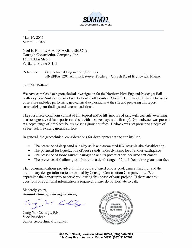
May 16, 2013 Summit #13057 Noel E. Rollins, AIA, NCARB, LEED GA Consigli Construction Company, Inc. 15 Franklin Street Portland, Maine 04101 Reference: Geotechnical Engineering Services
NNEPRA 1201 Amtrak Layover Facility – Church Road Brunswick, Maine Dear Mr. Rollins: We have completed our geotechnical investigation for the Northern New England Passenger Rail Authority new Amtrak Layover Facility located off Lombard Street in Brunswick, Maine. Our scope of services included performing geotechnical explorations at the site and preparing this report summarizing our findings and recommendations. The subsurface conditions consist of thin topsoil and/or fill (mixture of sand with coal ash) overlying marine regressive delta deposits (sand-silt with localized layers of silt-clay). Groundwater was present at a depth range of 2 to 9 feet below existing ground surface. Bedrock was not present to a depth of 92 feet below existing ground surface. In general, the geotechnical considerations for development at the site include:
The presence of deep sand-silt-clay soils and associated IBC seismic site classification. The potential for liquefaction of loose sands under dynamic loads and/or earthquake The presence of loose sand-silt subgrade and its potential for localized settlement The presence of shallow groundwater at a depth range of 2 to 9 feet below ground surface
The recommendations provided in this report are based on our geotechnical findings and the preliminary design information provided by Consigli Construction Company, Inc. We appreciate the opportunity to serve you during this phase of your project. If there are any questions or additional information is required, please do not hesitate to call. Sincerely yours, Summit Geoengineering Services,
Craig W. Coolidge, P.E. Vice President Senior Geotechnical Engineer
3
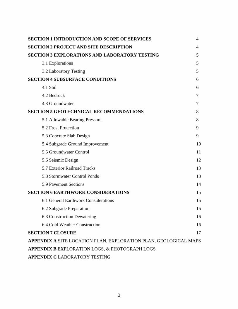
SECTION 1 INTRODUCTION AND SCOPE OF SERVICES 4
SECTION 2 PROJECT AND SITE DESCRIPTION 4
SECTION 3 EXPLORATIONS AND LABORATORY TESTING 5
3.1 Explorations 5
3.2 Laboratory Testing 5
SECTION 4 SUBSURFACE CONDITIONS 6
4.1 Soil 6
4.2 Bedrock 7
4.3 Groundwater 7
SECTION 5 GEOTECHNICAL RECOMMENDATIONS 8
5.1 Allowable Bearing Pressure 8
5.2 Frost Protection 9
5.3 Concrete Slab Design 9
5.4 Subgrade Ground Improvement 10
5.5 Groundwater Control 11
5.6 Seismic Design 12
5.7 Exterior Railroad Tracks 13
5.8 Stormwater Control Ponds 13
5.9 Pavement Sections 14
SECTION 6 EARTHWORK CONSIDERATIONS 15
6.1 General Earthwork Considerations 15
6.2 Subgrade Preparation 15
6.3 Construction Dewatering 16
6.4 Cold Weather Construction 16
SECTION 7 CLOSURE 17
APPENDIX A SITE LOCATION PLAN, EXPLORATION PLAN, GEOLOGICAL MAPS
APPENDIX B EXPLORATION LOGS, & PHOTOGRAPH LOGS
APPENDIX C LABORATORY TESTING
4
SECTION 1 INTRODUCTION AND SCOPE OF SERVICES
Summit Geoengineering Services (SGS) was contracted by Consigli Construction Company, Inc. to perform geotechnical investigations and prepare this report summarizing our findings and recommendations for the proposed Amtrak Layover Facility at a vacant site located off Church Road in Brunswick, Maine. Our scope of services included performing geotechnical explorations, pertinent laboratory testing, and preparing this report summarizing our findings and geotechnical recommendations. This report does not include an environmental assessment or further investigation into the presence or absence of contaminated soil or groundwater. Any comments regarding the nature and composition of the subsurface materials discovered are intended for informational purposes only.
SECTION 2 PROJECT AND SITE DESCRIPTION
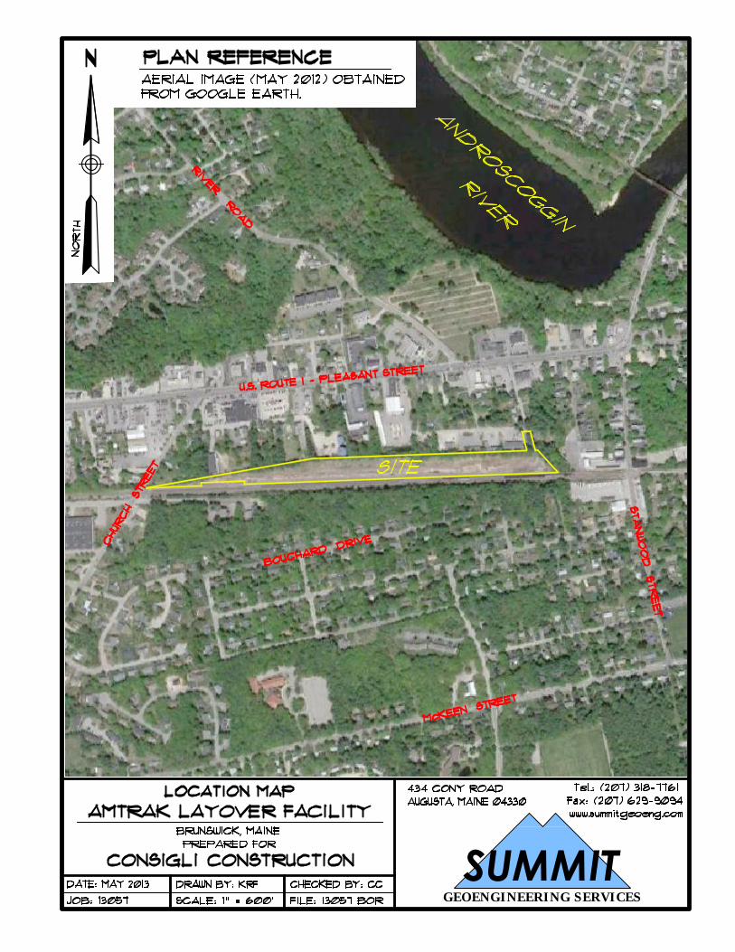
The project consists of the design and construction of the Amtrak Layover Facility being proposed within a vacant site located off Church Road in Brunswick, Maine. The anticipated development includes the following:
New steel frame building structure having a footprint of 51,000 ft2 New railroad entry and exit tracks (3 total) through building from existing tracks New bituminous pavement sections for access drive and parking spaces New stormwater treatment ponds (2 total) at each end of the site development
Currently the site contains an existing gravel drive, former railroad line, and recently cleared wooded areas. The site is located adjacent to existing Pan Am railroad lines currently in service. The is bordered by the existing railroad lines to the south, housing and commercial development along Route 1 to the north, Church Road to the west, and commercial development to the east. The site is access by Church Road to the west and Lombard Street to the east. Existing grades at the site slope west to east from elevation 90 feet along Church Road to elevation 75 feet at Lombard Street. Grades within the proposed building footprint range from elevations 84 feet to 80 feet west to east. We understand the proposed finish floor elevation for the building slab is elevation 81.43 feet. Project building foundation and train load design information used for our geotechnical evaluation include the following:
Conventional spread footing with slab on grade foundation Maximum column load of 75 kips Maximum wall load of 7.5 kips per linear foot Column spacing of 25 feet center on center Cooper E80 train loading Individual concrete slabs beneath each interior railroad track
5
SECTION 3
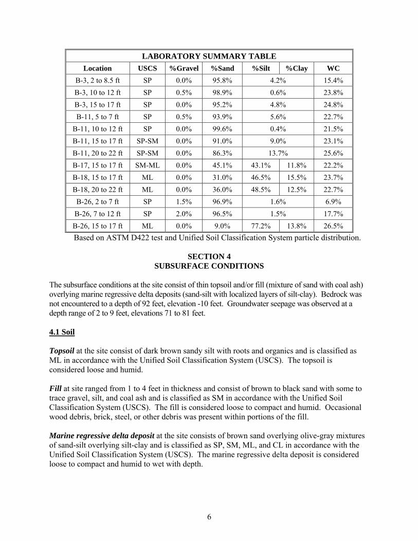
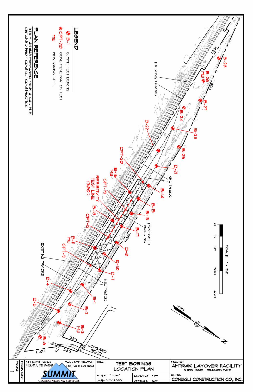
EXPLORATIONS AND LABORATORY TESTING 3.1 Exploration Summit Geoengineering Services (SGS) observed the subsurface conditions at the site with the drilling of 24 borings on April 22 through 25, 2013. The borings were advanced to depths of 12 to 22 feet using a rubber track mounted PowerProbe 9500 VTR. Borings were advanced using 3.5 inch direct push casing with SPT split spoon sampling. Groundwater monitoring wells were installed at 4 boring locations (B-3, B-11, B-16, and B-26). Cone Penetration Testing (CPT) was performed by Summit Geoengineering Services (SGS) on April 25 and 26, 2013 at 4 locations along the centerline of the building footprint referred to as boring locations (B-9, B-12, B-19, and B-20). CPT was performed using a rubber track mounted PowerProbe 9500 VTR with a single point hollow stem anchor set to a depth of 5 feet. CPT was performed using a Vertek 10 ton digital cone pushed to a depth of 49 to 92 feet at a constant rate (2 cm/s). Parameters obtained include cone resistance (qc), sleeve friction (fs), and piezocone pore pressure (u). Seismic testing was performed at 1-meter (3.3-foot) intervals during the CPT test to obtain shear wave velocity data. Resistivity testing was performed within the centerline of the building footprint using the Wenner Four Probe method in accordance with ASTM G57-06. Probes were aligned in an east to west alignment. Probe spacing ranged from 2 to 100 feet using 5-foot spacing. The explorations were survey located prior to performing the explorations by TKM Land Surveyors Inc under contract to others. Locations of the explorations are shown on Test Boring Location Plan in Appendix A. Photograph logs and exploration logs for the test borings, cone penetration testing (CPT), and resistivity testing are provided in Appendix B. Due to the presence of private utilities Dig Smart of Maine was subcontracted by Summit Geoengineering Services (SGS) to assist with locating underground utilities prior to performing the boring explorations. 3.2 Laboratory Testing One sample was tested for Atterberg Limits in accordance with ASTM D4318 and for moisture content in accordance with ASTM D2216. Result of the Atterberg Limit indicates liquid limit of 24, plastic index 7, and moisture content of 26.1 percent. Thirteen samples were tested for grain size analyses in accordance with ASTM D422 and for moisture content in accordance with ASTM D2216. Detailed results of the laboratory tests are provided in Appendix C. A summary of the gradation results and moisture contents are presented below:
6
LABORATORY SUMMARY TABLE
Location USCS %Gravel %Sand %Silt %Clay WC
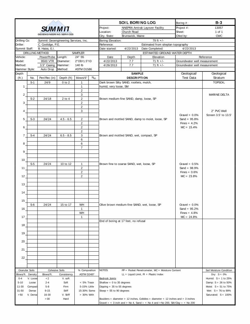
B-3, 2 to 8.5 ft SP 0.0% 95.8% 4.2% 15.4%
B-3, 10 to 12 ft SP 0.5% 98.9% 0.6% 23.8%
B-3, 15 to 17 ft SP 0.0% 95.2% 4.8% 24.8%
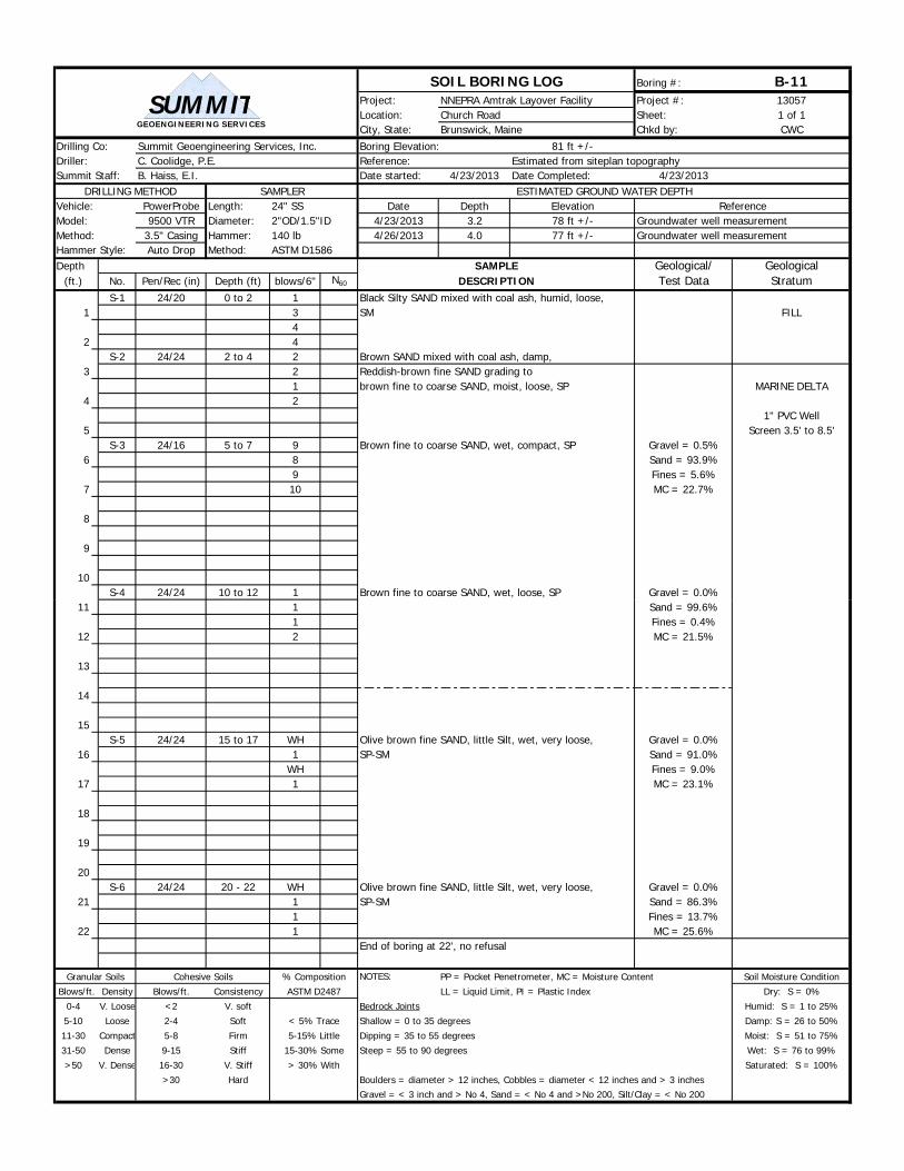
B-11, 5 to 7 ft SP 0.5% 93.9% 5.6% 22.7%
B-11, 10 to 12 ft SP 0.0% 99.6% 0.4% 21.5%
B-11, 15 to 17 ft SP-SM 0.0% 91.0% 9.0% 23.1%
B-11, 20 to 22 ft SP-SM 0.0% 86.3% 13.7% 25.6%
B-17, 15 to 17 ft SM-ML 0.0% 45.1% 43.1% 11.8% 22.2%
B-18, 15 to 17 ft ML 0.0% 31.0% 46.5% 15.5% 23.7%
B-18, 20 to 22 ft ML 0.0% 36.0% 48.5% 12.5% 22.7%
B-26, 2 to 7 ft SP 1.5% 96.9% 1.6% 6.9%
B-26, 7 to 12 ft SP 2.0% 96.5% 1.5% 17.7%
B-26, 15 to 17 ft ML 0.0% 9.0% 77.2% 13.8% 26.5%
Based on ASTM D422 test and Unified Soil Classification System particle distribution.
SECTION 4 SUBSURFACE CONDITIONS
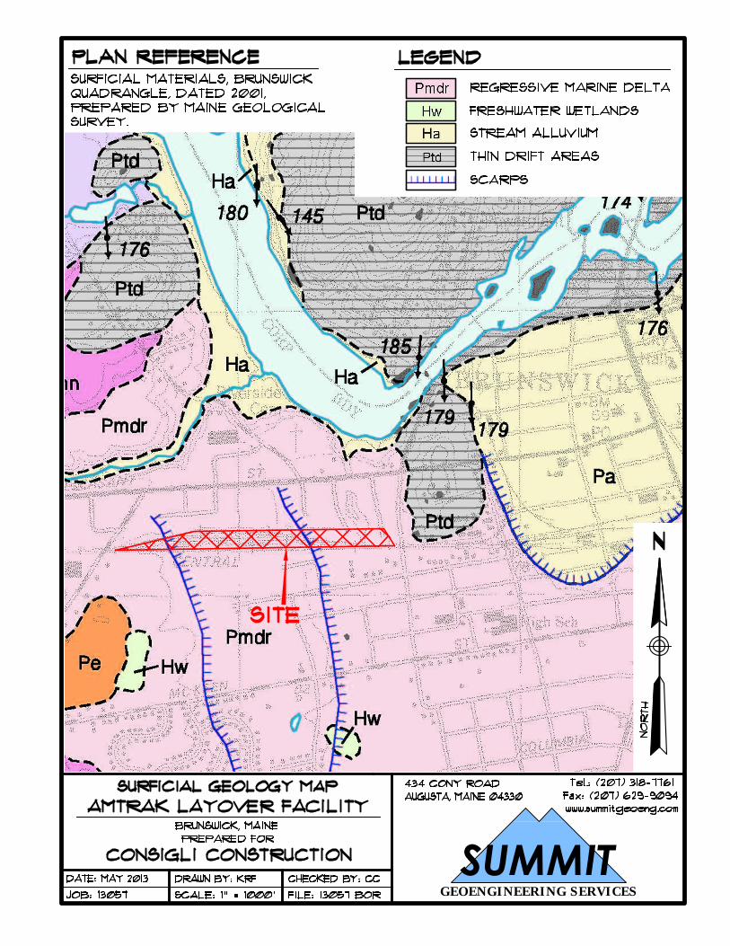
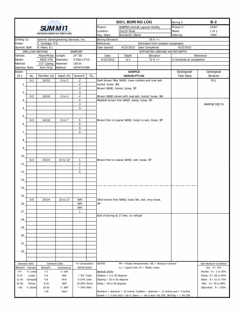
The subsurface conditions at the site consist of thin topsoil and/or fill (mixture of sand with coal ash) overlying marine regressive delta deposits (sand-silt with localized layers of silt-clay). Bedrock was not encountered to a depth of 92 feet, elevation -10 feet. Groundwater seepage was observed at a depth range of 2 to 9 feet, elevations 71 to 81 feet. 4.1 Soil Topsoil at the site consist of dark brown sandy silt with roots and organics and is classified as ML in accordance with the Unified Soil Classification System (USCS). The topsoil is considered loose and humid. Fill at site ranged from 1 to 4 feet in thickness and consist of brown to black sand with some to trace gravel, silt, and coal ash and is classified as SM in accordance with the Unified Soil Classification System (USCS). The fill is considered loose to compact and humid. Occasional wood debris, brick, steel, or other debris was present within portions of the fill. Marine regressive delta deposit at the site consists of brown sand overlying olive-gray mixtures of sand-silt overlying silt-clay and is classified as SP, SM, ML, and CL in accordance with the Unified Soil Classification System (USCS). The marine regressive delta deposit is considered loose to compact and humid to wet with depth.
7
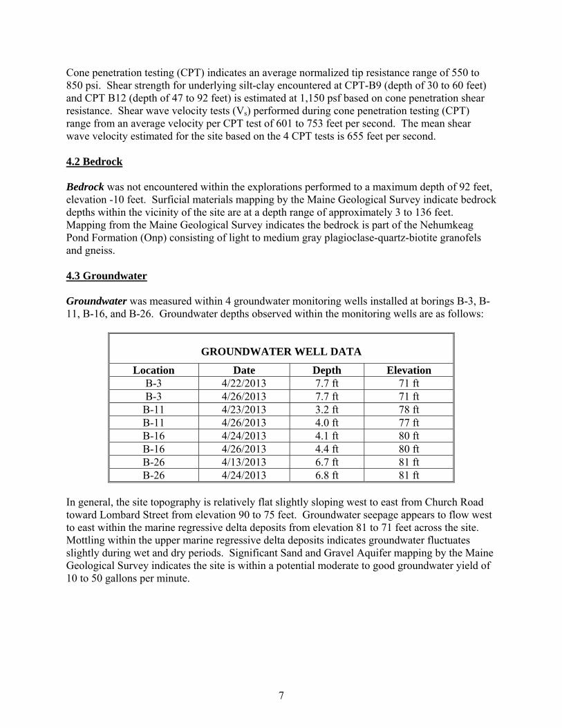
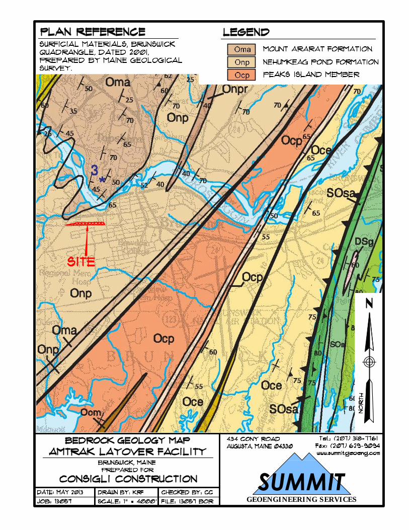
Cone penetration testing (CPT) indicates an average normalized tip resistance range of 550 to 850 psi. Shear strength for underlying silt-clay encountered at CPT-B9 (depth of 30 to 60 feet) and CPT B12 (depth of 47 to 92 feet) is estimated at 1,150 psf based on cone penetration shear resistance. Shear wave velocity tests (Vs) performed during cone penetration testing (CPT) range from an average velocity per CPT test of 601 to 753 feet per second. The mean shear wave velocity estimated for the site based on the 4 CPT tests is 655 feet per second. 4.2 Bedrock Bedrock was not encountered within the explorations performed to a maximum depth of 92 feet, elevation -10 feet. Surficial materials mapping by the Maine Geological Survey indicate bedrock depths within the vicinity of the site are at a depth range of approximately 3 to 136 feet. Mapping from the Maine Geological Survey indicates the bedrock is part of the Nehumkeag Pond Formation (Onp) consisting of light to medium gray plagioclase-quartz-biotite granofels and gneiss. 4.3 Groundwater Groundwater was measured within 4 groundwater monitoring wells installed at borings B-3, B-11, B-16, and B-26. Groundwater depths observed within the monitoring wells are as follows:
GROUNDWATER WELL DATA
Location Date Depth Elevation B-3 4/22/2013 7.7 ft 71 ft B-3 4/26/2013 7.7 ft 71 ft B-11 4/23/2013 3.2 ft 78 ft B-11 4/26/2013 4.0 ft 77 ft B-16 4/24/2013 4.1 ft 80 ft B-16 4/26/2013 4.4 ft 80 ft B-26 4/13/2013 6.7 ft 81 ft B-26 4/24/2013 6.8 ft 81 ft
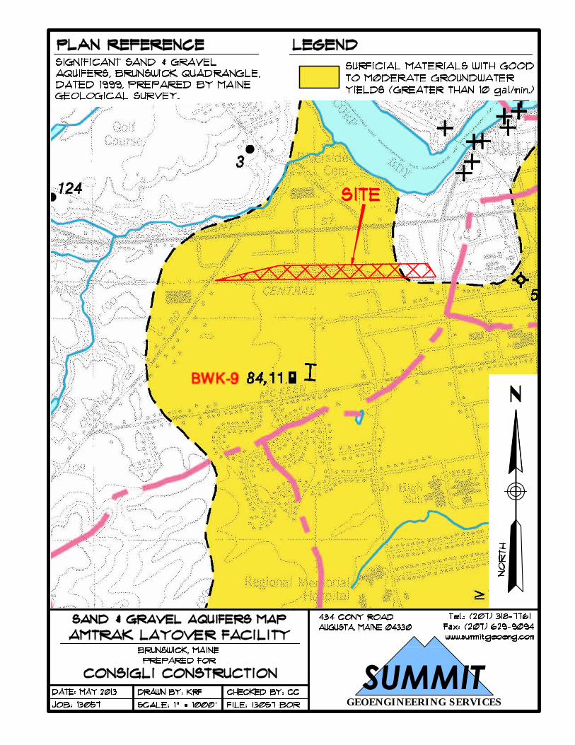
In general, the site topography is relatively flat slightly sloping west to east from Church Road toward Lombard Street from elevation 90 to 75 feet. Groundwater seepage appears to flow west to east within the marine regressive delta deposits from elevation 81 to 71 feet across the site. Mottling within the upper marine regressive delta deposits indicates groundwater fluctuates slightly during wet and dry periods. Significant Sand and Gravel Aquifer mapping by the Maine Geological Survey indicates the site is within a potential moderate to good groundwater yield of 10 to 50 gallons per minute.
8
SECTION 5
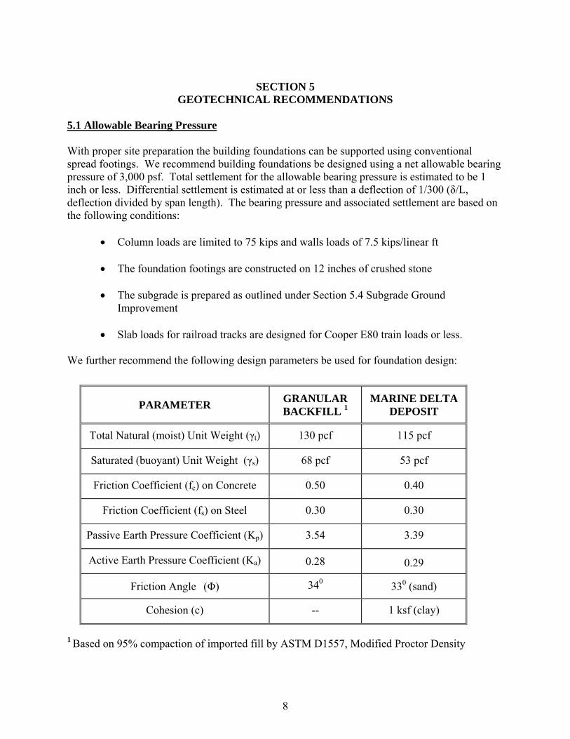
GEOTECHNICAL RECOMMENDATIONS 5.1 Allowable Bearing Pressure With proper site preparation the building foundations can be supported using conventional spread footings. We recommend building foundations be designed using a net allowable bearing pressure of 3,000 psf. Total settlement for the allowable bearing pressure is estimated to be 1 inch or less. Differential settlement is estimated at or less than a deflection of 1/300 (δ/L, deflection divided by span length). The bearing pressure and associated settlement are based on the following conditions:
Column loads are limited to 75 kips and walls loads of 7.5 kips/linear ft
The foundation footings are constructed on 12 inches of crushed stone
The subgrade is prepared as outlined under Section 5.4 Subgrade Ground Improvement
Slab loads for railroad tracks are designed for Cooper E80 train loads or less.
We further recommend the following design parameters be used for foundation design:
1 Based on 95% compaction of imported fill by ASTM D1557, Modified Proctor Density
PARAMETER GRANULAR BACKFILL 1
MARINE DELTA DEPOSIT
Total Natural (moist) Unit Weight (γt) 130 pcf 115 pcf
Saturated (buoyant) Unit Weight (γs) 68 pcf 53 pcf
Friction Coefficient (fc) on Concrete 0.50 0.40
Friction Coefficient (fs) on Steel 0.30 0.30
Passive Earth Pressure Coefficient (Kp) 3.54 3.39
Active Earth Pressure Coefficient (Ka) 0.28 0.29
Friction Angle (Φ) 340 330 (sand)
Cohesion (c) -- 1 ksf (clay)
9
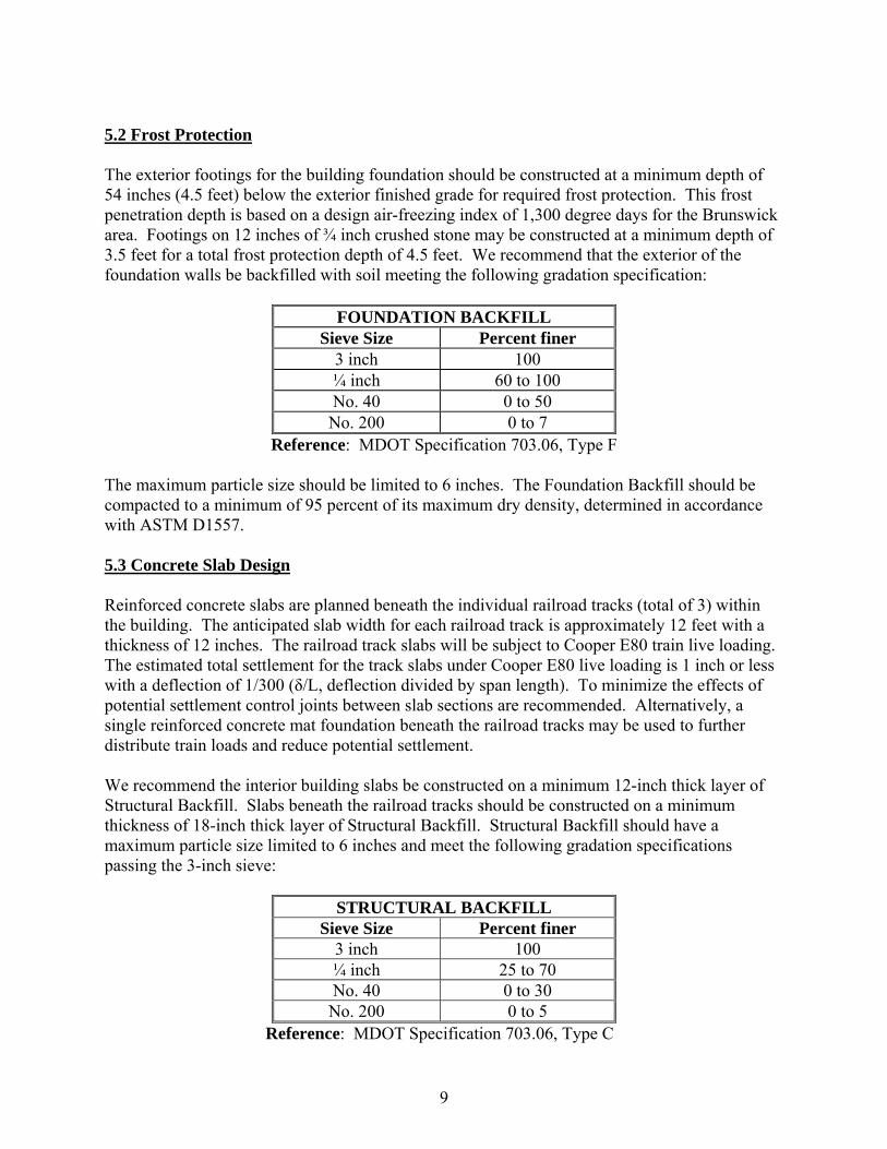
5.2 Frost Protection The exterior footings for the building foundation should be constructed at a minimum depth of 54 inches (4.5 feet) below the exterior finished grade for required frost protection. This frost penetration depth is based on a design air-freezing index of 1,300 degree days for the Brunswick area. Footings on 12 inches of ¾ inch crushed stone may be constructed at a minimum depth of 3.5 feet for a total frost protection depth of 4.5 feet. We recommend that the exterior of the foundation walls be backfilled with soil meeting the following gradation specification:
FOUNDATION BACKFILL Sieve Size Percent finer
3 inch 100 ¼ inch 60 to 100 No. 40 0 to 50 No. 200 0 to 7
Reference: MDOT Specification 703.06, Type F The maximum particle size should be limited to 6 inches. The Foundation Backfill should be compacted to a minimum of 95 percent of its maximum dry density, determined in accordance with ASTM D1557. 5.3 Concrete Slab Design Reinforced concrete slabs are planned beneath the individual railroad tracks (total of 3) within the building. The anticipated slab width for each railroad track is approximately 12 feet with a thickness of 12 inches. The railroad track slabs will be subject to Cooper E80 train live loading. The estimated total settlement for the track slabs under Cooper E80 live loading is 1 inch or less with a deflection of 1/300 (δ/L, deflection divided by span length). To minimize the effects of potential settlement control joints between slab sections are recommended. Alternatively, a single reinforced concrete mat foundation beneath the railroad tracks may be used to further distribute train loads and reduce potential settlement. We recommend the interior building slabs be constructed on a minimum 12-inch thick layer of Structural Backfill. Slabs beneath the railroad tracks should be constructed on a minimum thickness of 18-inch thick layer of Structural Backfill. Structural Backfill should have a maximum particle size limited to 6 inches and meet the following gradation specifications passing the 3-inch sieve:
STRUCTURAL BACKFILL Sieve Size Percent finer
3 inch 100 ¼ inch 25 to 70 No. 40 0 to 30 No. 200 0 to 5
Reference: MDOT Specification 703.06, Type C

10
The Structural Backfill should be placed in 6 to 12-inch lifts and should be compacted to 95 percent of its maximum dry density determined in accordance with ASTM D1557. Additional fill required beneath the slabs should consist of Structural Backfill. Where placement is required near or below groundwater crushed stone may be substituted for Structural Backfill. The subgrade should be prepared as outlined under Section 5.4 Subgrade Ground Improvement The coefficient of subgrade reaction, k (per 12-inch plate) applies to the design of reinforced concrete slabs over soil. We recommend a k value of 150 tons/ft3 for slabs constructed on compacted Structural Backfill. 5.4 Subgrade Ground Improvement Subgrade ground improvement is recommended prior to construction of building foundations, interior slabs, exterior railroad tracks, and pavement areas. Subgrade improvement is recommended to improve the density of underlying granular sand to improve bearing capacity and to minimize the effects of post construction settlement and potential for localized liquefaction due to surface dynamic loading. To improve subgrade density, a proof-rolling ground improvement program is recommended. We recommend the following be performed as subgrade preparation:
All topsoil/organics are removed prior to proof-rolling and Structural Backfill placement.
Subgrade is dewatered sufficiently to permit proof-rolling and/or excavation in the dry. Proof-rolling using large vibratory equipment is not recommended where groundwater is present within 2 feet of the top of grade due to its potential for liquefaction.
Where disturbed or liquefied subgrade is encountered it should be remove and replace with 12 inches of crushed stone and geotextile fabric such as Mirafi Polypropylene 500X.
Proof-rolling should consist of a minimum of five passes in a north-south direction and then five passes in an east-west direction using a large (15 ton operating weight) vibratory roller. Additional compaction passes should be performed as required to achieve sufficient compaction of subgrade. Proof-rolling should be performed prior to excavation for foundation footings.
Due to variability in subgrade sands, field inspection (observational method) of proof-rolling is recommended in place of conventional field density compaction testing to 95 percent of its maximum dry density determined in accordance with ASTM D1557. Field inspection should consist of performing initial field density testing prior to proof-rolling and subsequent field density testing after proof-rolling for comparison of density improvement. Additional compaction passes shall be made until the increase value in field density tests indicate that the maximum compaction has been achieved, thus field testing results will show no density improvement with additional compaction passes.
11
Moisture content for the subgrade sand should be evaluated by the geotechnical engineer to determine if additional water is necessary to improve proof-rolling efficiency. Laboratory maximum density tests (ASTM D1557) will assist with determining appropriate moisture content and corresponding density targets prior to performing the proof-rolling subgrade improvement. Oversight and review of the proof-rolling subgrade improvement should be performed by the geotechnical engineer.
5.5 Groundwater Control Groundwater within the building footprint was observed using monitoring wells at boring B-11 and B-16. Groundwater depths recorded within these observation wells indicate groundwater depths of 3.2 to 4.4 feet, elevations 77 to 80 feet. We understand the proposed finish floor elevation is 81.43 feet. Based on this groundwater is anticipated slightly below and near the finish floor elevation. Frost protection for the Brunswick area requires exterior footings to be constructed at a depth of 4.5 feet below grade. Based on this, the bottom of exterior footings is anticipated near elevation 77 feet. This will require footings to be constructed at or below groundwater depth. Due to the presence of groundwater, we recommend perimeter underdrains be installed along the base of the exterior foundation footings. Additional dewatering within the building footprint such as cutoff trenches or similar should also be considered to minimize the amount of groundwater above footing depths. Alternative, a reinforced mat foundation system could be utilized to eliminate foundation footings below groundwater. An increase in the finish floor elevation could also be used to elevate foundation footings above groundwater depths. Slab underdrains should be used beneath the foundation slabs to provide drainage during potential seasonal groundwater fluctuations. We recommend exterior grades slope away from the foundations to reduce runoff water from infiltrating the Foundation Backfill. Perimeter underdrains should consist of 4 inch rigid perforated PVC placed adjacent to the exterior footings and surrounded by a minimum of 6 inches of crushed stone wrapped in filter fabric to prevent clogging from the migration of the fine soil particles in the foundation backfill soils. The underdrain pipe should be outlet to a location where it will be free flowing. Where exposed at the ground surface, the ends of pipes should be screened or otherwise protected from entry and nesting of wildlife, which could cause clogging. Due to the sand subgrade, the potential for capillary rise, and close proximity to groundwater we recommend a vapor barrier be used beneath all building slabs. The vapor barrier should be installed in accordance with the latest ACI specifications (ACI 302.1R-96). Recommendations for groundwater dewatering during construction are provided in Section 6.3 Construction Dewatering.
12
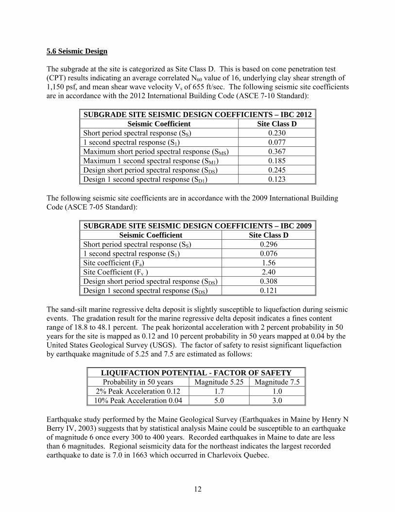
5.6 Seismic Design The subgrade at the site is categorized as Site Class D. This is based on cone penetration test (CPT) results indicating an average correlated N60 value of 16, underlying clay shear strength of 1,150 psf, and mean shear wave velocity Vs of 655 ft/sec. The following seismic site coefficients are in accordance with the 2012 International Building Code (ASCE 7-10 Standard):
SUBGRADE SITE SEISMIC DESIGN COEFFICIENTS – IBC 2012 Seismic Coefficient Site Class D
Short period spectral response (SS) 0.230 1 second spectral response (S1) 0.077 Maximum short period spectral response (SMS) 0.367 Maximum 1 second spectral response (SM1) 0.185 Design short period spectral response (SDS) 0.245 Design 1 second spectral response (SD1) 0.123
The following seismic site coefficients are in accordance with the 2009 International Building Code (ASCE 7-05 Standard):
SUBGRADE SITE SEISMIC DESIGN COEFFICIENTS – IBC 2009 Seismic Coefficient Site Class D
Short period spectral response (SS) 0.296 1 second spectral response (S1) 0.076 Site coefficient (Fa) 1.56 Site Coefficient (Fv ) 2.40 Design short period spectral response (SDS) 0.308 Design 1 second spectral response (SDS) 0.121
The sand-silt marine regressive delta deposit is slightly susceptible to liquefaction during seismic events. The gradation result for the marine regressive delta deposit indicates a fines content range of 18.8 to 48.1 percent. The peak horizontal acceleration with 2 percent probability in 50 years for the site is mapped as 0.12 and 10 percent probability in 50 years mapped at 0.04 by the United States Geological Survey (USGS). The factor of safety to resist significant liquefaction by earthquake magnitude of 5.25 and 7.5 are estimated as follows:
LIQUIFACTION POTENTIAL - FACTOR OF SAFETY Probability in 50 years Magnitude 5.25 Magnitude 7.5
2% Peak Acceleration 0.12 1.7 1.0 10% Peak Acceleration 0.04 5.0 3.0
Earthquake study performed by the Maine Geological Survey (Earthquakes in Maine by Henry N Berry IV, 2003) suggests that by statistical analysis Maine could be susceptible to an earthquake of magnitude 6 once every 300 to 400 years. Recorded earthquakes in Maine to date are less than 6 magnitudes. Regional seismicity data for the northeast indicates the largest recorded earthquake to date is 7.0 in 1663 which occurred in Charlevoix Quebec.

13
Based on the low probability for earthquakes in Maine to be greater than magnitude 6 and the mapped peak horizontal acceleration for the site, the potential for liquefaction during a seismic event is considered low and does not require ground improvement. 5.7 Exterior Railroad Tracks We understand 3 new exterior railroad tracks are planned as entrance-exit into the building structure and connecting to the existing Pan Am railroad line in current operation located adjacently south of the development site. In general we understand the proposed exterior tracks are planned at or near existing grades to be constructed on existing subgrade. Existing subgrade is anticipated at sandy fill and/or sand marine regressive delta deposits. We recommend subgrade beneath the new railroad track section be prepared as outlined under Section 5.4 Subgrade Ground Improvement. Structural design for the railroad track section should be in accordance with Cooper E80 live loading as outlined by The American Railway Engineering Association. We recommend railroad track section be designed using a net allowable bearing pressure of 3,000 psf or a coefficient of subgrade reaction k value of 150 tons/ft3. 5.8 Stormwater Control Ponds We understand two new storm water treatment ponds are proposed with one at the east corner of the site and the other at the west corner of the site. Design grades for the ponds have not yet been established for this report. Boring B-2 and B-3 were performed within the east pond footprint. Boring B-26 was performed within the west pond footprint. The subgrade within the east pond consists of brown sand of medium-loose density grading to fine sand explored to a depth of 17 feet, elevation 61 feet. Groundwater observed at the monitoring well installed at B-3 recorded groundwater at a depth of 7.7 feet, near elevation 71 feet. Based on the gradation results for samples obtained at boring B-3 and observed in-situ density of the sand subgrade, we recommend an infiltration rate of approximately 45 in/hr be used for the sand layer within the pond footprint. The subgrade within the west pond consists of brown sand of medium-loose density grading to olive brown silt encountered near a depth of 13 feet, elevation 75 feet. Groundwater observed at the monitoring well installed at B-26 recorded groundwater at a depth of 6.7 to 6.8 feet, near elevation 81 feet. Based on the gradation results for samples obtained at boring B-26 and observed in-situ density of the subgrade, we recommend an infiltration rate of approximately 75 in/hr be used for the upper sand layer and approximately 2 in/hr or less for the lower silt layer within the pond footprint. Subgrade conditions anticipated within the base of the pond is anticipated as medium-loose sand. Due to the presence of groundwater at or near the base of the pond and moderate susceptibility of sand to soften during excavation, conventional construction excavations may be difficult without a suitable plan for dewatering, water diversion, and stabilization.
14
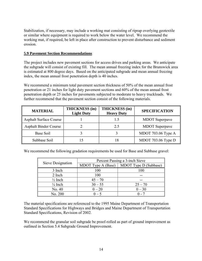
Stabilization, if necessary, may include a working mat consisting of riprap overlying geotextile or similar where equipment is required to work below the water level. We recommend the working mat, if required, be left in place after construction to prevent disturbance and sediment erosion. 5.9 Pavement Section Recommendations The project includes new pavement sections for access drives and parking areas. We anticipate the subgrade will consist of existing fill. The mean annual freezing index for the Brunswick area is estimated at 800 degree days. Based on the anticipated subgrade and mean annual freezing index, the mean annual frost penetration depth is 40 inches. We recommend a minimum total pavement section thickness of 50% of the mean annual frost penetration or 21 inches for light duty pavement sections and 60% of the mean annual frost penetration depth or 25 inches for pavements subjected to moderate to heavy truckloads. We further recommend that the pavement section consist of the following materials.
MATERIAL THICKNESS (in)
Light Duty THICKNESS (in)
Heavy Duty SPECIFICATION
Asphalt Surface Course 1 1.5 MDOT Superpave
Asphalt Binder Course 2 2.5 MDOT Superpave
Base Soil 3 3 MDOT 703.06 Type A
Subbase Soil 15 18 MDOT 703.06 Type D
We recommend the following gradation requirements be used for Base and Subbase gravel:
Sieve Designation Percent Passing a 3-inch Sieve
MDOT Type A (Base) MDOT Type D (Subbase) 3 Inch 100 100 2 Inch 100 -- ½ Inch 45 – 70 -- ¼ Inch 30 – 55 25 – 70 No. 40 0 – 20 0 – 30 No. 200 0 – 5 0 - 7
The material specifications are referenced to the 1995 Maine Department of Transportation Standard Specifications for Highways and Bridges and Maine Department of Transportation Standard Specifications, Revision of 2002. We recommend the granular soil subgrade be proof-rolled as part of ground improvement as outlined in Section 5.4 Subgrade Ground Improvement.
15
SECTION 6 EARTHWORK CONSIDERATIONS
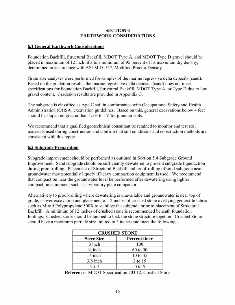
6.1 General Earthwork Considerations Foundation Backfill, Structural Backfill, MDOT Type A, and MDOT Type D gravel should be placed in maximum of 12 inch lifts to a minimum of 95 percent of its maximum dry density, determined in accordance with ASTM D1557, Modified Proctor Density. Grain size analyses were performed for samples of the marine regressive delta deposits (sand). Based on the gradation results, the marine regressive delta deposits (sand) does not meet specifications for Foundation Backfill, Structural Backfill, MDOT Type A, or Type D due to low gravel content. Gradation results are provided in Appendix C. The subgrade is classified as type C soil in conformance with Occupational Safety and Health Administration (OHSA) excavation guidelines. Based on this, general excavations below 4 feet should be sloped no greater than 1.5H to 1V for granular soils. We recommend that a qualified geotechnical consultant be retained to monitor and test soil materials used during construction and confirm that soil conditions and construction methods are consistent with this report. 6.2 Subgrade Preparation Subgrade improvement should be performed as outlined in Section 5.4 Subgrade Ground Improvement. Sand subgrade should be sufficiently dewatered to prevent subgrade liquefaction during proof rolling. Placement of Structural Backfill and proof-rolling of sand subgrade near groundwater may potentially liquefy if heavy compaction equipment is used. We recommend that compaction near the groundwater level be performed after dewatering using lighter compaction equipment such as a vibratory plate compactor. Alternatively to proof-rolling where dewatering is unavailable and groundwater is near top of grade, is over excavation and placement of 12 inches of crushed stone overlying geotextile fabric such as Mirafi Polypropylene 500X to stabilize the subgrade prior to placement of Structural Backfill. A minimum of 12 inches of crushed stone is recommended beneath foundation footings. Crushed stone should be tamped to lock the stone structure together. Crushed Stone should have a maximum particle size limited to 3 inches and meet the following:
CRUSHED STONE Sieve Size Percent finer
3 inch 100 ¾ inch 60 to 90 ½ inch 10 to 35
3/8 inch 2 to 15 No. 4 0 to 5
Reference: MDOT Specification 703.12, Crushed Stone
16
To prevent the migration of fines and to distribute foundation loads we recommend geotextile filter fabric such as Mirafi Polypropylene 500X or equivalent be placed between the stabilized subgrade and Foundation Backfill. Geotextile should be placed with a minimum overlap of 2 feet. A minimum soil lift section of 6 inches is recommended prior to tracking vehicles or equipment over geotextile to prevent damage. We recommend that Summit Geoengineering Services (SGS) be made available to visually inspect the subgrade during proof-rolling to verify the subgrade meets suitable preparation with our geotechnical recommendations. 6.3 Construction Dewatering Dewatering will be required for excavations 3 to 8 feet below existing grade. Dewatering may consist of shallow sumps, a well point system, or other dewatering methods. The upper subgrade soils (sand) are considered pervious with an estimated permeability of approximately 45 to 75 in/hr based on the gradation results. Significant Sand and Gravel Aquifer mapping by the Maine Geological Survey indicates the site is within a potential moderate to good groundwater yield of 10 to 50 gallons per minute. The contractor should furnish, install, operate, maintain, and remove the temporary dewatering systems to lower and control groundwater levels at least 2 feet below subgrade of excavations and to permit construction in-the-dry. Dewatering methods could include sump pumps placed at the base of a ¾ inch bedding stone layer. Pumps should be wrapped in approximately 6 to 12 inches of stone placed near the bottom of the excavation to reduce the amount of vacuum required to dewater the base of the excavation. The subgrade should be sloped to provide positive drainage to the sumps. Temporary groundwater diversion such as a cut-off trench, underdrains, or other suitable method to adequately prevent additional water flow from entering the foundation excavation should be used to permit excavation in the dry. Excavations should be sloped to prevent surface water from flowing into the excavations. For deeper excavations requiring a greater dewatering capacity, a well point dewatering system will be required. Should a well point system be selected it should be designed by a qualified engineer. Summit can be made available to provide this services if requested. 6.4 Cold Weather Construction The following recommendations apply to earthwork construction during freezing conditions. In general, these recommendations are intended to minimize the penetration of frost into soil beneath foundations. 1. Foundation excavations should be protected from frost overnight by the use of
insulated blankets or by tenting and heating.
17
2. Foundations should not be cast on frozen soil. The frozen zone should be removed and replaced as specified with the appropriate material.
3. Fill areas should be sealed with a 6 or 12 inch loose layer of soil (or otherwise
insulated) at the end of the day to protect the compacted soil from freezing. The frozen layers should be removed in the morning prior to placing and compacting the next lift.
4. Due to the difficulty of thawing previously frozen soils (even within a heated shell),
we recommend that the subgrade soil be protected from frost penetration where practical, especially if foundations are planned to be placed during periods of freezing.
5. Frozen foundation subgrade soils will become soft during thaw in the spring. We
recommend that heavy traffic be avoided during thawing. Once the soil thaws and the accumulated water in the soil has drained, the subgrade should return to a firm condition. If placement of the footings or slabs occurs during thaw, we recommend that soft areas be removed and replaced with the use of geotextile fabric and crushed stone to stabilize soft areas.
We recommend that all winter concrete construction be performed in accordance with ACI 306, Cold Weather Concreting.
SECTION 7 CLOSURE
Our recommendations are based on professional judgment and generally accepted principles of geotechnical engineering and project information provided by others. Some changes in subsurface conditions from those presented in this report may occur. Should these conditions differ materially from those described in this report, SGS should be notified so that we can re-evaluate our recommendations. It is recommended that this report be made available in its entirety to contractors for informational purposes and be incorporated in the construction Contract Documents. We recommend that SGS be retained to review final construction documents relevant to the recommendations in this report.
APPENDIX A SITE LOCATION PLAN
EXPLORATION LOCATION PLAN GEOLOGICAL MAPPING
GEOENGINEERING SERVICES
SUMMIT
GEOENGINEERING SERVICES
SUMMIT
GEOENGINEERING SERVICES
SUMMIT

GEOENGINEERING SERVICES
SUMMIT
37
GEOENGINEERING SERVICES
SUMMIT
GEOENGINEERING SERVICES
SUMMIT

APPENDIX B EXPLORATION LOGS
PHOTO LOGS

GEOENGINEERING SERVICES
SUMMIT
640 Main Street, Lewiston, Maine 04240, (207) 576-3313 434 Cony Road, Augusta, Maine 04330, (207) 318-7761
EXPLORATION COVER SHEET The exploration logs are prepared by the geotechnical engineer from both field and laboratory data. Soil descriptions are based upon the Unified Soil Classification System (USCS) per ASTM D2487 and/or ASTM D2488 as applicable. Supplemental descriptive terms for estimated particle percentage, color, density, moisture condition, and bedrock may also be included to further describe conditions. Drilling and Sampling Symbols: SS = Split Spoon Sample Hyd = Hydraulic Advancement of Drilling Rods UT = Thin Wall Shelby Tube Push = Direct Push of Drilling Rods SSA = Solid Stem Auger WOH = Weight of Hammer HSA = Hollow Stem Auger WOR = Weight of Rod RW = Rotary Wash PI = Plasticity Index SV = Shear Vane LL = Liquid Limit PP = Pocket Penetrometer W = Natural Water Content RC = Rock Core Sample USCS = Unified Soil Classification System Water Level Measurements: Water levels indicated on the boring logs are the levels measured in the boring at the times indicated. In pervious soils, the indicated elevations are considered reliable groundwater levels. In impervious soils, the accurate determination of groundwater elevations may not be possible, even after several days of observations. Groundwater monitoring wells may be required to record accurate depths and fluctuation. Gradation Description and Terminology: Boulders: Over 12 inches Trace: Less than 5% Cobbles: 12 inches to 3 inches Little: 5% to 15% Gravel: 3 inches to No.4 sieve Some: 15% to 30% Sand: No.4 to No. 200 sieve Silty, Sandy, etc.: Greater than 30% Silt: No. 200 sieve to 0.005 mm Clay: less than 0.005 mm Density of Granular Soils and Consistency of Cohesive Soils:
CONSISTENCY OF COHESIVE SOILS DENSITY OF GRANULAR SOILS SPT N-value blows/ft Consistency SPT N-value blows/ft Relative Density
0 to 2 Very Soft 0 to 4 Very Loose 2 to 4 Soft 5 to 10 Loose 5 to 8 Firm 11 to 30 Compact
9 to 15 Stiff 31 to 50 Dense 16 to 30 Very Stiff >50 Very Dense
>30 Hard

SOIL BORING LOG Boring #: B-1Project: NNEPRA Amtrak Layover Facility Project #: 13057Location: Church Road Sheet: 1 of 1City, State: Brunswick, Maine Chkd by: CWC
Drilling Co: Summit Geoengineering Services, Inc. Boring Elevation: 79 ft +/-Driller: C. Coolidge, P.E. Reference: Estimated from siteplan topographySummit Staff: B. Haiss, E.I. Date started: 4/22/2013 Date Completed: 4/22/2013
DRILLING METHOD SAMPLER ESTIMATED GROUND WATER DEPTHVehicle: PowerProbe Length: Date Depth Elevation ReferenceModel: 9500 VTR Diameter: 4/22/2013 6.2 73 ft +/- In borehole at completionMethod: 3.5" Casing Hammer:Hammer Style: Auto Drop Method:Depth SAMPLE Geological/ Geological
(ft.) No. Pen/Rec (in) Depth (ft) blows/6" N60 DESCRIPTION Test Data StratumS-1 24/20 0 to 2 1 Dark brown Silty SAND, trace rootlets and coal ash, FILL
1 1 humid, very loose, SM2
2 4 Brown SAND, humid, compact, SP MARINE DELTAS-2 24/2 2 to 4 4
3 44
4 3
5S-3 24/24 5 to 7 2 Olive brown Silty SAND, moist, compact, SM
6 5 grading to8 Mottled brown SAND, moist, compact, SW
7 5
8
9
10S-4 24/24 10 to 12 2 Brown fine to coarse SAND, wet, loose, SP
24" SS2"OD/1.5"ID140 lbASTM D1586
GEOENGINEERING SERVICES
SUMMIT
11 22
12 2 Olive gray Silt-Clay at spoon tipEnd of boring at 12 feet, no refusal
13
14
15
16
17
18
19
20
21
22
Granular Soils Cohesive Soils NOTES: PP = Pocket Penetrometer, MC = Moisture Content Soil Moisture Condition
Blows/ft. Density Blows/ft. Consistency LL = Liquid Limit, PI = Plastic Index Dry: S = 0%
0-4 V. Loose <2 V. soft Bedrock Joints Humid: S = 1 to 25%
5-10 Loose 2-4 Soft Shallow = 0 to 35 degrees Damp: S = 26 to 50%
11-30 Compact 5-8 Firm Dipping = 35 to 55 degrees Moist: S = 51 to 75%
31-50 Dense 9-15 Stiff Steep = 55 to 90 degrees Wet: S = 76 to 99%
>50 V. Dense 16-30 V. Stiff Saturated: S = 100%
>30 Hard Boulders = diameter > 12 inches, Cobbles = diameter < 12 inches and > 3 inchesGravel = < 3 inch and > No 4, Sand = < No 4 and >No 200, Silt/Clay = < No 200
% Composition
ASTM D2487
< 5% Trace
5-15% Little
15-30% Some
> 30% With
SOIL BORING LOG Boring #: B-2Project: NNEPRA Amtrak Layover Facility Project #: 13057Location: Church Road Sheet: 1 of 1City, State: Brunswick, Maine Chkd by: CWC
Drilling Co: Summit Geoengineering Services, Inc. Boring Elevation: 78 ft +/-Driller: C. Coolidge, P.E. Reference: Estimated from siteplan topographySummit Staff: B. Haiss, E.I. Date started: 4/22/2013 Date Completed: 4/22/2013
DRILLING METHOD SAMPLER ESTIMATED GROUND WATER DEPTHVehicle: PowerProbe Length: Date Depth Elevation ReferenceModel: 9500 VTR Diameter: 4/22/2013 6.1 72 ft +/- In borehole at completionMethod: 3.5" Casing Hammer:Hammer Style: Auto Drop Method:Depth SAMPLE Geological/ Geological
(ft.) No. Pen/Rec (in) Depth (ft) blows/6" N60 DESCRIPTION Test Data StratumS-1 24/10 0 to 2 2 Dark brown Silty SAND, trace rootlets and coal ash, FILL
1 4 humid, loose, SM3 Brown SAND, humid, loose, SP
2 3S-2 24/18 2 to 4 4 Brown SAND mixed with coal ash, humid, loose, SM
3 5 Reddish-brown fine SAND, damp, loose, SP3 MARINE DELTA
4 3
5S-3 24/18 5 to 7 6 Brown fine to coarse SAND, moist to wet, loose, SP
6 55
7 4
8
9
10S-4 24/24 10 to 12 1 Brown fine to coarse SAND, wet, loose, SP
24" SS2"OD/1.5"ID140 lbASTM D1586
GEOENGINEERING SERVICES
SUMMIT
11 21
12 5
13
14
15S-5 24/24 15 to 17 WH Olive brown fine SAND, trace Silt, wet, very loose,
16 WH SPWH
17 1End of boring at 17 feet, no refusal
18
19
20
21
22
Granular Soils Cohesive Soils NOTES: PP = Pocket Penetrometer, MC = Moisture Content Soil Moisture Condition
Blows/ft. Density Blows/ft. Consistency LL = Liquid Limit, PI = Plastic Index Dry: S = 0%
0-4 V. Loose <2 V. soft Bedrock Joints Humid: S = 1 to 25%
5-10 Loose 2-4 Soft Shallow = 0 to 35 degrees Damp: S = 26 to 50%
11-30 Compact 5-8 Firm Dipping = 35 to 55 degrees Moist: S = 51 to 75%
31-50 Dense 9-15 Stiff Steep = 55 to 90 degrees Wet: S = 76 to 99%
>50 V. Dense 16-30 V. Stiff Saturated: S = 100%
>30 Hard Boulders = diameter > 12 inches, Cobbles = diameter < 12 inches and > 3 inchesGravel = < 3 inch and > No 4, Sand = < No 4 and >No 200, Silt/Clay = < No 200
% Composition
ASTM D2487
< 5% Trace
5-15% Little
15-30% Some
> 30% With
SOIL BORING LOG Boring #: B-3Project: NNEPRA Amtrak Layover Facility Project #: 13057Location: Church Road Sheet: 1 of 1City, State: Brunswick, Maine Chkd by: CWC
Drilling Co: Summit Geoengineering Services, Inc. Boring Elevation: 79 ft +/-Driller: C. Coolidge, P.E. Reference: Estimated from siteplan topographySummit Staff: B. Haiss, E.I. Date started: 4/22/2013 Date Completed: 4/22/2013
DRILLING METHOD SAMPLER ESTIMATED GROUND WATER DEPTHVehicle: PowerProbe Length: Date Depth Elevation ReferenceModel: 9500 VTR Diameter: 4/22/2013 7.7 71 ft +/- Groundwater well measurementMethod: 3.5" Casing Hammer: 4/26/2013 7.7 71 ft +/- Groundwater well measurementHammer Style: Auto Drop Method:Depth SAMPLE Geological/ Geological
(ft.) No. Pen/Rec (in) Depth (ft) blows/6" N60 DESCRIPTION Test Data StratumS-1 24/9 0 to 2 1 Dark brown Silty SAND, rootlets, mulch, TOPSOIL
1 1 humid, very loose, SM2
2 3 MARINE DELTAS-2 24/18 2 to 4 2 Brown medium-fine SAND, damp, loose, SP
3 22
4 3 2" PVC WellGravel = 0.0% Screen 3.5' to 13.5'
5 S-3 24/24 4.5 - 6.5 2 Brown and mottled SAND, damp to moist, loose, SP Sand = 95.8%2 Fines = 4.2%
6 2 MC = 15.4%2
7 S-4 24/24 6.5 - 8.5 3 Brown and mottled SAND, wet, compact, SP6
8 67
9
10S-5 24/24 10 to 12 1 Brown fine to coarse SAND, wet, loose, SP Gravel = 0.5%
24" SS2"OD/1.5"ID140 lbASTM D1586
GEOENGINEERING SERVICES
SUMMIT
11 2 Sand = 98.9%2 Fines = 0.6%
12 2 MC = 23.8%
13
14
15S-6 24/24 15 to 17 WH Olive brown medium-fine SAND, wet, loose, SP Gravel = 0.0%
16 1 Sand = 95.2%WH Fines = 4.8%
17 1 MC = 24.8%End of boring at 17 feet, no refusal
18
19
20
21
22
Granular Soils Cohesive Soils NOTES: PP = Pocket Penetrometer, MC = Moisture Content Soil Moisture Condition
Blows/ft. Density Blows/ft. Consistency LL = Liquid Limit, PI = Plastic Index Dry: S = 0%
0-4 V. Loose <2 V. soft Bedrock Joints Humid: S = 1 to 25%
5-10 Loose 2-4 Soft Shallow = 0 to 35 degrees Damp: S = 26 to 50%
11-30 Compact 5-8 Firm Dipping = 35 to 55 degrees Moist: S = 51 to 75%
31-50 Dense 9-15 Stiff Steep = 55 to 90 degrees Wet: S = 76 to 99%
>50 V. Dense 16-30 V. Stiff Saturated: S = 100%
>30 Hard Boulders = diameter > 12 inches, Cobbles = diameter < 12 inches and > 3 inchesGravel = < 3 inch and > No 4, Sand = < No 4 and >No 200, Silt/Clay = < No 200
% Composition
ASTM D2487
< 5% Trace
5-15% Little
15-30% Some
> 30% With
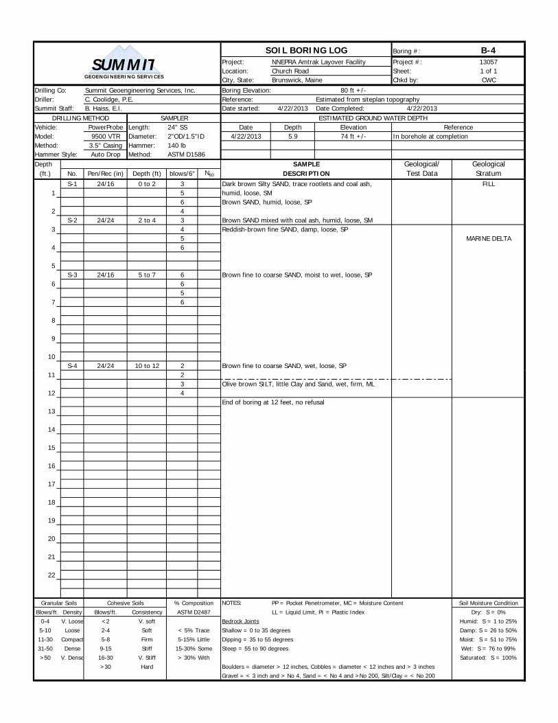
SOIL BORING LOG Boring #: B-4Project: NNEPRA Amtrak Layover Facility Project #: 13057Location: Church Road Sheet: 1 of 1City, State: Brunswick, Maine Chkd by: CWC
Drilling Co: Summit Geoengineering Services, Inc. Boring Elevation: 80 ft +/-Driller: C. Coolidge, P.E. Reference: Estimated from siteplan topographySummit Staff: B. Haiss, E.I. Date started: 4/22/2013 Date Completed: 4/22/2013
DRILLING METHOD SAMPLER ESTIMATED GROUND WATER DEPTHVehicle: PowerProbe Length: Date Depth Elevation ReferenceModel: 9500 VTR Diameter: 4/22/2013 5.9 74 ft +/- In borehole at completionMethod: 3.5" Casing Hammer:Hammer Style: Auto Drop Method:Depth SAMPLE Geological/ Geological
(ft.) No. Pen/Rec (in) Depth (ft) blows/6" N60 DESCRIPTION Test Data StratumS-1 24/16 0 to 2 3 Dark brown Silty SAND, trace rootlets and coal ash, FILL
1 5 humid, loose, SM6 Brown SAND, humid, loose, SP
2 4S-2 24/24 2 to 4 3 Brown SAND mixed with coal ash, humid, loose, SM
3 4 Reddish-brown fine SAND, damp, loose, SP5 MARINE DELTA
4 6
5S-3 24/16 5 to 7 6 Brown fine to coarse SAND, moist to wet, loose, SP
6 65
7 6
8
9
10S-4 24/24 10 to 12 2 Brown fine to coarse SAND, wet, loose, SP
24" SS2"OD/1.5"ID140 lbASTM D1586
GEOENGINEERING SERVICES
SUMMIT
11 23 Olive brown SILT, little Clay and Sand, wet, firm, ML
12 4End of boring at 12 feet, no refusal
13
14
15
16
17
18
19
20
21
22
Granular Soils Cohesive Soils NOTES: PP = Pocket Penetrometer, MC = Moisture Content Soil Moisture Condition
Blows/ft. Density Blows/ft. Consistency LL = Liquid Limit, PI = Plastic Index Dry: S = 0%
0-4 V. Loose <2 V. soft Bedrock Joints Humid: S = 1 to 25%
5-10 Loose 2-4 Soft Shallow = 0 to 35 degrees Damp: S = 26 to 50%
11-30 Compact 5-8 Firm Dipping = 35 to 55 degrees Moist: S = 51 to 75%
31-50 Dense 9-15 Stiff Steep = 55 to 90 degrees Wet: S = 76 to 99%
>50 V. Dense 16-30 V. Stiff Saturated: S = 100%
>30 Hard Boulders = diameter > 12 inches, Cobbles = diameter < 12 inches and > 3 inchesGravel = < 3 inch and > No 4, Sand = < No 4 and >No 200, Silt/Clay = < No 200
% Composition
ASTM D2487
< 5% Trace
5-15% Little
15-30% Some
> 30% With
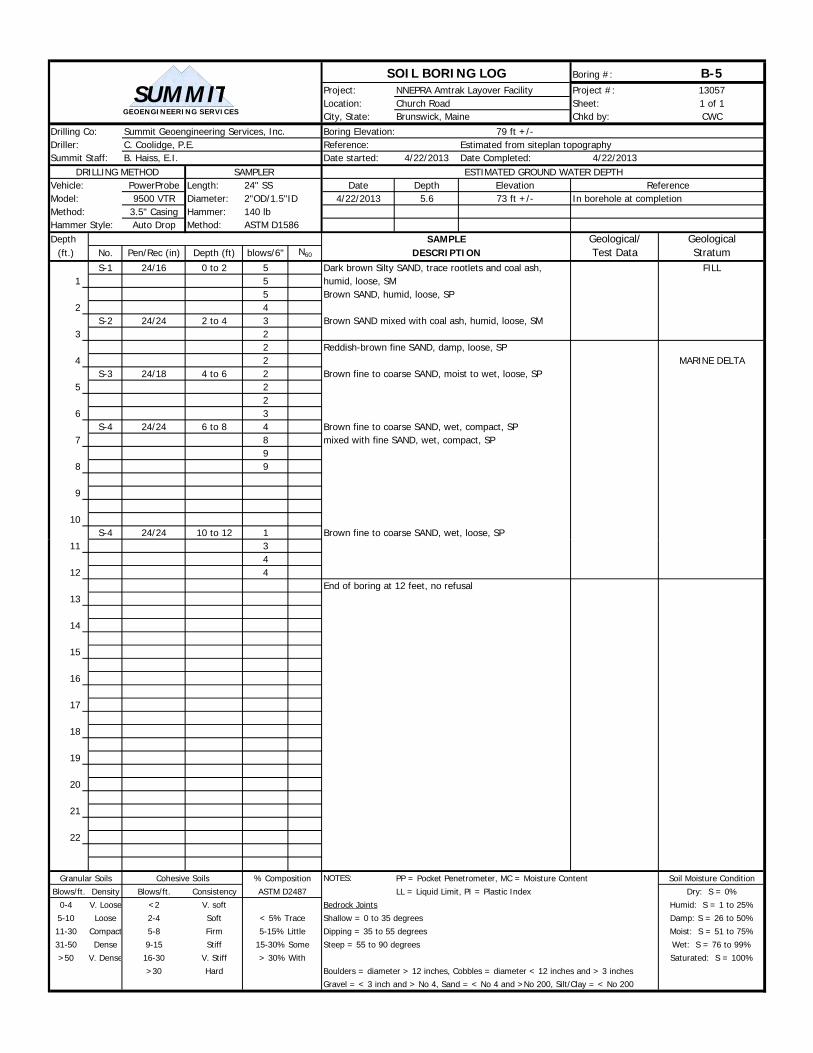
SOIL BORING LOG Boring #: B-5Project: NNEPRA Amtrak Layover Facility Project #: 13057Location: Church Road Sheet: 1 of 1City, State: Brunswick, Maine Chkd by: CWC
Drilling Co: Summit Geoengineering Services, Inc. Boring Elevation: 79 ft +/-Driller: C. Coolidge, P.E. Reference: Estimated from siteplan topographySummit Staff: B. Haiss, E.I. Date started: 4/22/2013 Date Completed: 4/22/2013
DRILLING METHOD SAMPLER ESTIMATED GROUND WATER DEPTHVehicle: PowerProbe Length: Date Depth Elevation ReferenceModel: 9500 VTR Diameter: 4/22/2013 5.6 73 ft +/- In borehole at completionMethod: 3.5" Casing Hammer:Hammer Style: Auto Drop Method:Depth SAMPLE Geological/ Geological
(ft.) No. Pen/Rec (in) Depth (ft) blows/6" N60 DESCRIPTION Test Data StratumS-1 24/16 0 to 2 5 Dark brown Silty SAND, trace rootlets and coal ash, FILL
1 5 humid, loose, SM5 Brown SAND, humid, loose, SP
2 4S-2 24/24 2 to 4 3 Brown SAND mixed with coal ash, humid, loose, SM
3 22 Reddish-brown fine SAND, damp, loose, SP
4 2 MARINE DELTAS-3 24/18 4 to 6 2 Brown fine to coarse SAND, moist to wet, loose, SP
5 22
6 3S-4 24/24 6 to 8 4 Brown fine to coarse SAND, wet, compact, SP
7 8 mixed with fine SAND, wet, compact, SP9
8 9
9
10S-4 24/24 10 to 12 1 Brown fine to coarse SAND, wet, loose, SP
24" SS2"OD/1.5"ID140 lbASTM D1586
GEOENGINEERING SERVICES
SUMMIT
11 34
12 4End of boring at 12 feet, no refusal
13
14
15
16
17
18
19
20
21
22
Granular Soils Cohesive Soils NOTES: PP = Pocket Penetrometer, MC = Moisture Content Soil Moisture Condition
Blows/ft. Density Blows/ft. Consistency LL = Liquid Limit, PI = Plastic Index Dry: S = 0%
0-4 V. Loose <2 V. soft Bedrock Joints Humid: S = 1 to 25%
5-10 Loose 2-4 Soft Shallow = 0 to 35 degrees Damp: S = 26 to 50%
11-30 Compact 5-8 Firm Dipping = 35 to 55 degrees Moist: S = 51 to 75%
31-50 Dense 9-15 Stiff Steep = 55 to 90 degrees Wet: S = 76 to 99%
>50 V. Dense 16-30 V. Stiff Saturated: S = 100%
>30 Hard Boulders = diameter > 12 inches, Cobbles = diameter < 12 inches and > 3 inchesGravel = < 3 inch and > No 4, Sand = < No 4 and >No 200, Silt/Clay = < No 200
% Composition
ASTM D2487
< 5% Trace
5-15% Little
15-30% Some
> 30% With
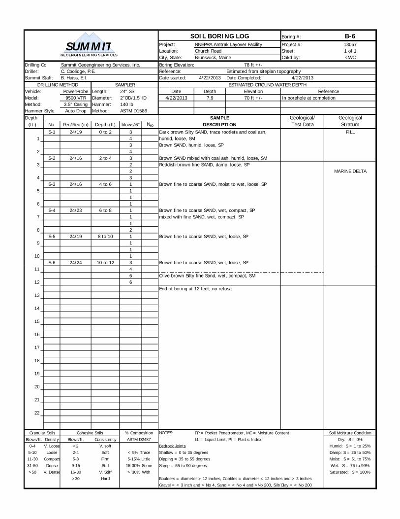
SOIL BORING LOG Boring #: B-6Project: NNEPRA Amtrak Layover Facility Project #: 13057Location: Church Road Sheet: 1 of 1City, State: Brunswick, Maine Chkd by: CWC
Drilling Co: Summit Geoengineering Services, Inc. Boring Elevation: 78 ft +/-Driller: C. Coolidge, P.E. Reference: Estimated from siteplan topographySummit Staff: B. Haiss, E.I. Date started: 4/22/2013 Date Completed: 4/22/2013
DRILLING METHOD SAMPLER ESTIMATED GROUND WATER DEPTHVehicle: PowerProbe Length: Date Depth Elevation ReferenceModel: 9500 VTR Diameter: 4/22/2013 7.9 70 ft +/- In borehole at completionMethod: 3.5" Casing Hammer:Hammer Style: Auto Drop Method:Depth SAMPLE Geological/ Geological
(ft.) No. Pen/Rec (in) Depth (ft) blows/6" N60 DESCRIPTION Test Data StratumS-1 24/19 0 to 2 3 Dark brown Silty SAND, trace rootlets and coal ash, FILL
1 4 humid, loose, SM3 Brown SAND, humid, loose, SP
2 4S-2 24/16 2 to 4 3 Brown SAND mixed with coal ash, humid, loose, SM
3 2 Reddish-brown fine SAND, damp, loose, SP2 MARINE DELTA
4 3S-3 24/16 4 to 6 1 Brown fine to coarse SAND, moist to wet, loose, SP
5 11
6 1S-4 24/23 6 to 8 1 Brown fine to coarse SAND, wet, compact, SP
7 1 mixed with fine SAND, wet, compact, SP1
8 2S-5 24/19 8 to 10 1 Brown fine to coarse SAND, wet, loose, SP
9 11
10 1S-6 24/24 10 to 12 3 Brown fine to coarse SAND, wet, loose, SP
24" SS2"OD/1.5"ID140 lbASTM D1586
GEOENGINEERING SERVICES
SUMMIT
11 46 Olive brown Silty fine Sand, wet, compact, SM
12 6End of boring at 12 feet, no refusal
13
14
15
16
17
18
19
20
21
22
Granular Soils Cohesive Soils NOTES: PP = Pocket Penetrometer, MC = Moisture Content Soil Moisture Condition
Blows/ft. Density Blows/ft. Consistency LL = Liquid Limit, PI = Plastic Index Dry: S = 0%
0-4 V. Loose <2 V. soft Bedrock Joints Humid: S = 1 to 25%
5-10 Loose 2-4 Soft Shallow = 0 to 35 degrees Damp: S = 26 to 50%
11-30 Compact 5-8 Firm Dipping = 35 to 55 degrees Moist: S = 51 to 75%
31-50 Dense 9-15 Stiff Steep = 55 to 90 degrees Wet: S = 76 to 99%
>50 V. Dense 16-30 V. Stiff Saturated: S = 100%
>30 Hard Boulders = diameter > 12 inches, Cobbles = diameter < 12 inches and > 3 inchesGravel = < 3 inch and > No 4, Sand = < No 4 and >No 200, Silt/Clay = < No 200
% Composition
ASTM D2487
< 5% Trace
5-15% Little
15-30% Some
> 30% With
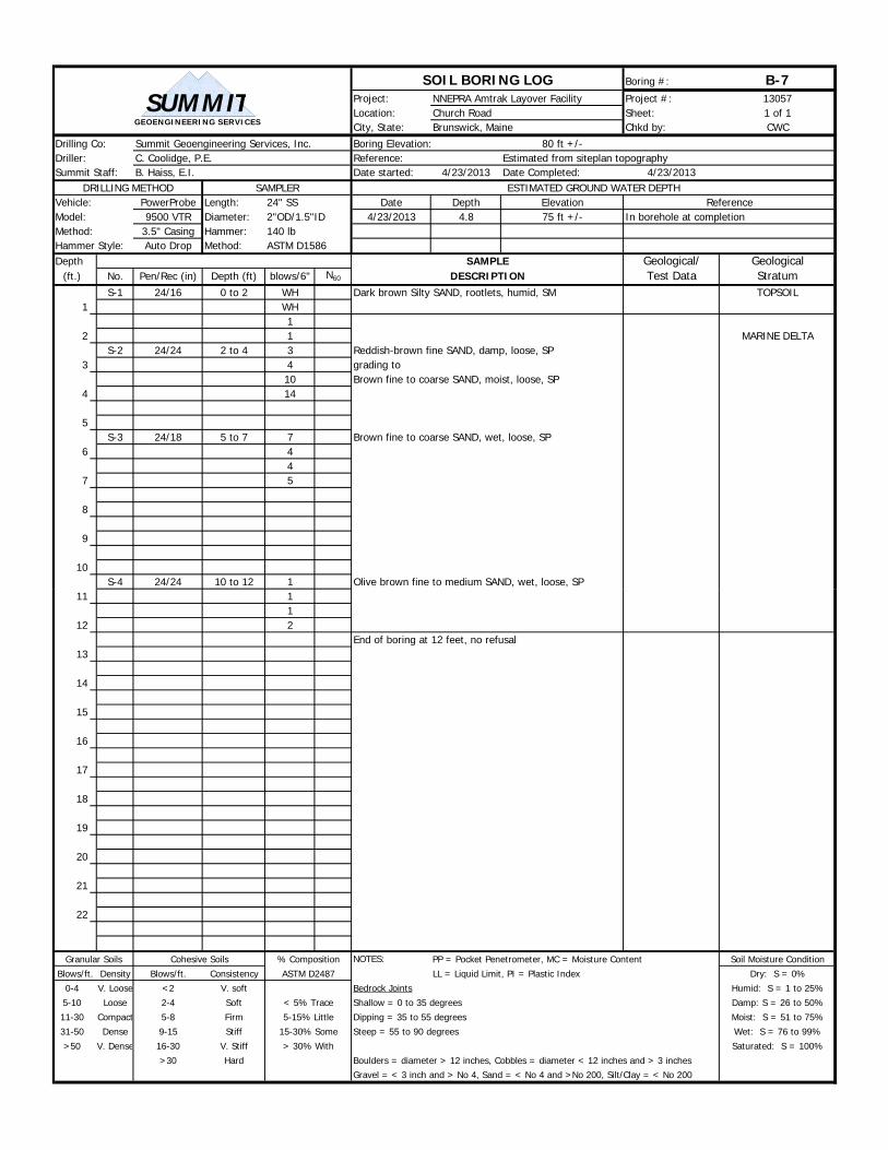
SOIL BORING LOG Boring #: B-7Project: NNEPRA Amtrak Layover Facility Project #: 13057Location: Church Road Sheet: 1 of 1City, State: Brunswick, Maine Chkd by: CWC
Drilling Co: Summit Geoengineering Services, Inc. Boring Elevation: 80 ft +/-Driller: C. Coolidge, P.E. Reference: Estimated from siteplan topographySummit Staff: B. Haiss, E.I. Date started: 4/23/2013 Date Completed: 4/23/2013
DRILLING METHOD SAMPLER ESTIMATED GROUND WATER DEPTHVehicle: PowerProbe Length: Date Depth Elevation ReferenceModel: 9500 VTR Diameter: 4/23/2013 4.8 75 ft +/- In borehole at completionMethod: 3.5" Casing Hammer:Hammer Style: Auto Drop Method:Depth SAMPLE Geological/ Geological
(ft.) No. Pen/Rec (in) Depth (ft) blows/6" N60 DESCRIPTION Test Data StratumS-1 24/16 0 to 2 WH Dark brown Silty SAND, rootlets, humid, SM TOPSOIL
1 WH1
2 1 MARINE DELTAS-2 24/24 2 to 4 3 Reddish-brown fine SAND, damp, loose, SP
3 4 grading to10 Brown fine to coarse SAND, moist, loose, SP
4 14
5S-3 24/18 5 to 7 7 Brown fine to coarse SAND, wet, loose, SP
6 44
7 5
8
9
10S-4 24/24 10 to 12 1 Olive brown fine to medium SAND, wet, loose, SP
24" SS2"OD/1.5"ID140 lbASTM D1586
GEOENGINEERING SERVICES
SUMMIT
11 11
12 2End of boring at 12 feet, no refusal
13
14
15
16
17
18
19
20
21
22
Granular Soils Cohesive Soils NOTES: PP = Pocket Penetrometer, MC = Moisture Content Soil Moisture Condition
Blows/ft. Density Blows/ft. Consistency LL = Liquid Limit, PI = Plastic Index Dry: S = 0%
0-4 V. Loose <2 V. soft Bedrock Joints Humid: S = 1 to 25%
5-10 Loose 2-4 Soft Shallow = 0 to 35 degrees Damp: S = 26 to 50%
11-30 Compact 5-8 Firm Dipping = 35 to 55 degrees Moist: S = 51 to 75%
31-50 Dense 9-15 Stiff Steep = 55 to 90 degrees Wet: S = 76 to 99%
>50 V. Dense 16-30 V. Stiff Saturated: S = 100%
>30 Hard Boulders = diameter > 12 inches, Cobbles = diameter < 12 inches and > 3 inchesGravel = < 3 inch and > No 4, Sand = < No 4 and >No 200, Silt/Clay = < No 200
% Composition
ASTM D2487
< 5% Trace
5-15% Little
15-30% Some
> 30% With

SOIL BORING LOG Boring #: B-8Project: NNEPRA Amtrak Layover Facility Project #: 13057Location: Church Road Sheet: 1 of 1City, State: Brunswick, Maine Chkd by: CWC
Drilling Co: Summit Geoengineering Services, Inc. Boring Elevation: 81 ft +/-Driller: C. Coolidge, P.E. Reference: Estimated from siteplan topographySummit Staff: B. Haiss, E.I. Date started: 4/23/2013 Date Completed: 4/23/2013
DRILLING METHOD SAMPLER ESTIMATED GROUND WATER DEPTHVehicle: PowerProbe Length: Date Depth Elevation ReferenceModel: 9500 VTR Diameter: 4/23/2013 3.4 78 ft +/- In borehole at completionMethod: 3.5" Casing Hammer:Hammer Style: Auto Drop Method:Depth SAMPLE Geological/ Geological
(ft.) No. Pen/Rec (in) Depth (ft) blows/6" N60 DESCRIPTION Test Data StratumS-1 24/16 0 to 2 WH Dark brown Silty SAND, rootlets, humid, SM TOPSOIL
1 1WH
2 1 MARINE DELTAS-2 24/24 2 to 4 4 Reddish-brown fine SAND, damp, loose, SP
3 10 grading to12 Brown fine to coarse SAND, moist, loose, SP
4 8
5S-3 24/24 5 to 7 1 Brown fine to coarse SAND, wet, loose, SP
6 35
7 6
8
9
10S-4 24/24 10 to 12 WH Brown fine to coarse SAND, wet, loose, SP
24" SS2"OD/1.5"ID140 lbASTM D1586
GEOENGINEERING SERVICES
SUMMIT
11 WH5
12 4End of boring at 12 feet, no refusal
13
14
15
16
17
18
19
20
21
22
Granular Soils Cohesive Soils NOTES: PP = Pocket Penetrometer, MC = Moisture Content Soil Moisture Condition
Blows/ft. Density Blows/ft. Consistency LL = Liquid Limit, PI = Plastic Index Dry: S = 0%
0-4 V. Loose <2 V. soft Bedrock Joints Humid: S = 1 to 25%
5-10 Loose 2-4 Soft Shallow = 0 to 35 degrees Damp: S = 26 to 50%
11-30 Compact 5-8 Firm Dipping = 35 to 55 degrees Moist: S = 51 to 75%
31-50 Dense 9-15 Stiff Steep = 55 to 90 degrees Wet: S = 76 to 99%
>50 V. Dense 16-30 V. Stiff Saturated: S = 100%
>30 Hard Boulders = diameter > 12 inches, Cobbles = diameter < 12 inches and > 3 inchesGravel = < 3 inch and > No 4, Sand = < No 4 and >No 200, Silt/Clay = < No 200
% Composition
ASTM D2487
< 5% Trace
5-15% Little
15-30% Some
> 30% With

SOIL BORING LOG Boring #: B-10Project: NNEPRA Amtrak Layover Facility Project #: 13057Location: Church Road Sheet: 1 of 1City, State: Brunswick, Maine Chkd by: CWC
Drilling Co: Summit Geoengineering Services, Inc. Boring Elevation: 81 ft +/-Driller: C. Coolidge, P.E. Reference: Estimated from siteplan topographySummit Staff: B. Haiss, E.I. Date started: 4/23/2013 Date Completed: 4/23/2013
DRILLING METHOD SAMPLER ESTIMATED GROUND WATER DEPTHVehicle: PowerProbe Length: Date Depth Elevation ReferenceModel: 9500 VTR Diameter: 4/23/2013 2.9 78 ft +/- In borehole at completionMethod: 3.5" Casing Hammer:Hammer Style: Auto Drop Method:Depth SAMPLE Geological/ Geological
(ft.) No. Pen/Rec (in) Depth (ft) blows/6" N60 DESCRIPTION Test Data StratumS-1 24/16 0 to 2 1 Dark brown Silty SAND, rootlets, mulch, humid, SM TOPSOIL
1 11
2 1 MARINE DELTAS-2 24/24 2 to 4 3 Reddish-brown fine SAND, damp, loose, SP
3 15 grading to19 Brown fine to coarse SAND, moist, loose, SP
4 24
5S-3 24/20 5 to 7 14 Brown fine to coarse SAND, wet, loose, SP
6 109
7 7
8
9
10S-4 24/24 10 to 12 WH Brown fine to coarse SAND, wet, loose, SP
24" SS2"OD/1.5"ID140 lbASTM D1586
GEOENGINEERING SERVICES
SUMMIT
11 WH1
12 2
13
14
15S-5 0/0 15 to 17 NA No sample - running sands plugged casing
16 (brown fine-coarse SAND, wet, SP in sampler)
17
18
19
20S-6 24/24 20 - 22 WH Olive brown fine SAND, trace Silt, wet, compact, SP
21 65
22 8End of boring at 22', no refusal
Granular Soils Cohesive Soils NOTES: PP = Pocket Penetrometer, MC = Moisture Content Soil Moisture Condition
Blows/ft. Density Blows/ft. Consistency LL = Liquid Limit, PI = Plastic Index Dry: S = 0%
0-4 V. Loose <2 V. soft Bedrock Joints Humid: S = 1 to 25%
5-10 Loose 2-4 Soft Shallow = 0 to 35 degrees Damp: S = 26 to 50%
11-30 Compact 5-8 Firm Dipping = 35 to 55 degrees Moist: S = 51 to 75%
31-50 Dense 9-15 Stiff Steep = 55 to 90 degrees Wet: S = 76 to 99%
>50 V. Dense 16-30 V. Stiff Saturated: S = 100%
>30 Hard Boulders = diameter > 12 inches, Cobbles = diameter < 12 inches and > 3 inchesGravel = < 3 inch and > No 4, Sand = < No 4 and >No 200, Silt/Clay = < No 200
% Composition
ASTM D2487
< 5% Trace
5-15% Little
15-30% Some
> 30% With
SOIL BORING LOG Boring #: B-11Project: NNEPRA Amtrak Layover Facility Project #: 13057Location: Church Road Sheet: 1 of 1City, State: Brunswick, Maine Chkd by: CWC
Drilling Co: Summit Geoengineering Services, Inc. Boring Elevation: 81 ft +/-Driller: C. Coolidge, P.E. Reference: Estimated from siteplan topographySummit Staff: B. Haiss, E.I. Date started: 4/23/2013 Date Completed: 4/23/2013
DRILLING METHOD SAMPLER ESTIMATED GROUND WATER DEPTHVehicle: PowerProbe Length: Date Depth Elevation ReferenceModel: 9500 VTR Diameter: 4/23/2013 3.2 78 ft +/- Groundwater well measurementMethod: 3.5" Casing Hammer: 4/26/2013 4.0 77 ft +/- Groundwater well measurementHammer Style: Auto Drop Method:Depth SAMPLE Geological/ Geological
(ft.) No. Pen/Rec (in) Depth (ft) blows/6" N60 DESCRIPTION Test Data StratumS-1 24/20 0 to 2 1 Black Silty SAND mixed with coal ash, humid, loose,
1 3 SM FILL4
2 4S-2 24/24 2 to 4 2 Brown SAND mixed with coal ash, damp,
3 2 Reddish-brown fine SAND grading to1 brown fine to coarse SAND, moist, loose, SP MARINE DELTA
4 21" PVC Well
5 Screen 3.5' to 8.5'S-3 24/16 5 to 7 9 Brown fine to coarse SAND, wet, compact, SP Gravel = 0.5%
6 8 Sand = 93.9%9 Fines = 5.6%
7 10 MC = 22.7%
8
9
10S-4 24/24 10 to 12 1 Brown fine to coarse SAND, wet, loose, SP Gravel = 0.0%
24" SS2"OD/1.5"ID140 lbASTM D1586
GEOENGINEERING SERVICES
SUMMIT
11 1 Sand = 99.6%1 Fines = 0.4%
12 2 MC = 21.5%
13
14
15S-5 24/24 15 to 17 WH Olive brown fine SAND, little Silt, wet, very loose, Gravel = 0.0%
16 1 SP-SM Sand = 91.0%WH Fines = 9.0%
17 1 MC = 23.1%
18
19
20S-6 24/24 20 - 22 WH Olive brown fine SAND, little Silt, wet, very loose, Gravel = 0.0%
21 1 SP-SM Sand = 86.3%1 Fines = 13.7%
22 1 MC = 25.6%End of boring at 22', no refusal
Granular Soils Cohesive Soils NOTES: PP = Pocket Penetrometer, MC = Moisture Content Soil Moisture Condition
Blows/ft. Density Blows/ft. Consistency LL = Liquid Limit, PI = Plastic Index Dry: S = 0%
0-4 V. Loose <2 V. soft Bedrock Joints Humid: S = 1 to 25%
5-10 Loose 2-4 Soft Shallow = 0 to 35 degrees Damp: S = 26 to 50%
11-30 Compact 5-8 Firm Dipping = 35 to 55 degrees Moist: S = 51 to 75%
31-50 Dense 9-15 Stiff Steep = 55 to 90 degrees Wet: S = 76 to 99%
>50 V. Dense 16-30 V. Stiff Saturated: S = 100%
>30 Hard Boulders = diameter > 12 inches, Cobbles = diameter < 12 inches and > 3 inchesGravel = < 3 inch and > No 4, Sand = < No 4 and >No 200, Silt/Clay = < No 200
% Composition
ASTM D2487
< 5% Trace
5-15% Little
15-30% Some
> 30% With
SOIL BORING LOG Boring #: B-13Project: NNEPRA Amtrak Layover Facility Project #: 13057Location: Church Road Sheet: 1 of 1City, State: Brunswick, Maine Chkd by: CWC
Drilling Co: Summit Geoengineering Services, Inc. Boring Elevation: 82 ft +/-Driller: C. Coolidge, P.E. Reference: Estimated from siteplan topographySummit Staff: B. Peterlein, P.E. Date started: 4/24/2013 Date Completed: 4/24/2013
DRILLING METHOD SAMPLER ESTIMATED GROUND WATER DEPTHVehicle: PowerProbe Length: Date Depth Elevation ReferenceModel: 9500 VTR Diameter: 4/24/2013 2.1 80 ft +/- In borehole at completionMethod: 3.5" Casing Hammer:Hammer Style: Auto Drop Method:Depth SAMPLE Geological/ Geological
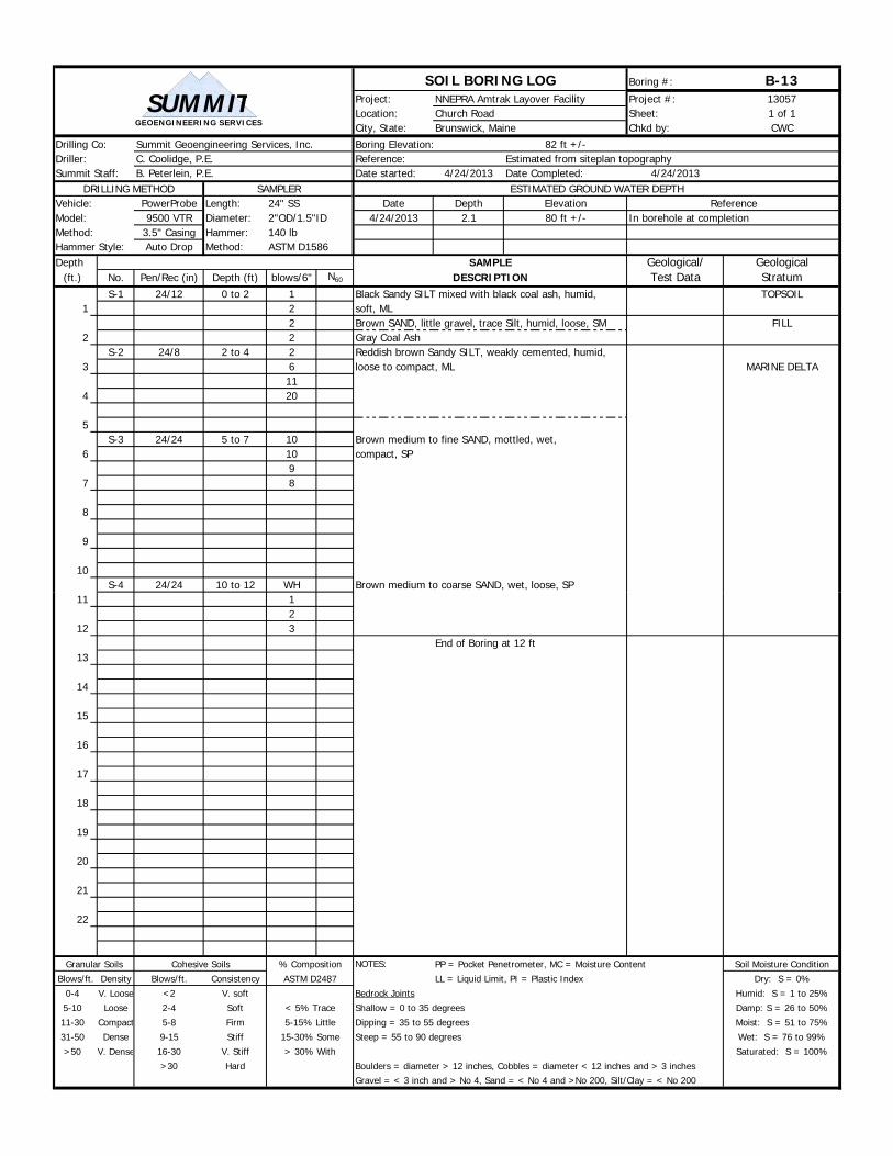
(ft.) No. Pen/Rec (in) Depth (ft) blows/6" N60 DESCRIPTION Test Data StratumS-1 24/12 0 to 2 1 Black Sandy SILT mixed with black coal ash, humid, TOPSOIL
1 2 soft, ML2 Brown SAND, little gravel, trace Silt, humid, loose, SM FILL
2 2 Gray Coal AshS-2 24/8 2 to 4 2 Reddish brown Sandy SILT, weakly cemented, humid,
3 6 loose to compact, ML MARINE DELTA11
4 20
5S-3 24/24 5 to 7 10 Brown medium to fine SAND, mottled, wet,
6 10 compact, SP9
7 8
8
9
10S-4 24/24 10 to 12 WH Brown medium to coarse SAND, wet, loose, SP
24" SS2"OD/1.5"ID140 lbASTM D1586
GEOENGINEERING SERVICES
SUMMIT
11 12
12 3End of Boring at 12 ft
13
14
15
16
17
18
19
20
21
22
Granular Soils Cohesive Soils NOTES: PP = Pocket Penetrometer, MC = Moisture Content Soil Moisture Condition
Blows/ft. Density Blows/ft. Consistency LL = Liquid Limit, PI = Plastic Index Dry: S = 0%
0-4 V. Loose <2 V. soft Bedrock Joints Humid: S = 1 to 25%
5-10 Loose 2-4 Soft Shallow = 0 to 35 degrees Damp: S = 26 to 50%
11-30 Compact 5-8 Firm Dipping = 35 to 55 degrees Moist: S = 51 to 75%
31-50 Dense 9-15 Stiff Steep = 55 to 90 degrees Wet: S = 76 to 99%
>50 V. Dense 16-30 V. Stiff Saturated: S = 100%
>30 Hard Boulders = diameter > 12 inches, Cobbles = diameter < 12 inches and > 3 inchesGravel = < 3 inch and > No 4, Sand = < No 4 and >No 200, Silt/Clay = < No 200
< 5% Trace
5-15% Little
15-30% Some
> 30% With
% Composition
ASTM D2487

SOIL BORING LOG Boring #: B-14Project: NNEPRA Amtrak Layover Facility Project #: 13057Location: Church Road Sheet: 1 of 1City, State: Brunswick, Maine Chkd by: CWC
Drilling Co: Summit Geoengineering Services, Inc. Boring Elevation: 83 ft +/-Driller: C. Coolidge, P.E. Reference: Estimated from siteplan topographySummit Staff: B. Peterlein, P.E. Date started: 4/24/2013 Date Completed: 4/24/2013
DRILLING METHOD SAMPLER ESTIMATED GROUND WATER DEPTHVehicle: PowerProbe Length: Date Depth Elevation ReferenceModel: 9500 VTR Diameter: 4/24/2013 3.8 79 ft +/- In borehole at completionMethod: 3.5" Casing Hammer:Hammer Style: Auto Drop Method:Depth SAMPLE Geological/ Geological
(ft.) No. Pen/Rec (in) Depth (ft) blows/6" N60 DESCRIPTION Test Data StratumS-1 24/18 0 to 2 WH Dark brown Sandy SILT, trace rootlets, humid, ML TOPSOIL
1 1 Brown medium to fine SAND, trace Silt, heavily1 mottled, humid, very loose, SP MARINE DELTA
2 1S-2 24/18 2 to 4 2 Olive-tan SAND, little Silt, grading to dark brown Silty
3 3 find Sand, humid, loose, SM4
4 6
5S-3 24/18 5 to 7 9 Brown medium to coarse SAND, wet, compact, SP
6 86
7 5
8
9
10S-4 24/20 10 to 12 2 Brown medium to coarse SAND, wet, compact, SP
24" SS2"OD/1.5"ID140 lbASTM D1586
GEOENGINEERING SERVICES
SUMMIT
11 13
12 4End of Test Pit at 12 feet
13
14
15
16
17
18
19
20
21
22
Granular Soils Cohesive Soils NOTES: PP = Pocket Penetrometer, MC = Moisture Content Soil Moisture Condition
Blows/ft. Density Blows/ft. Consistency LL = Liquid Limit, PI = Plastic Index Dry: S = 0%
0-4 V. Loose <2 V. soft Bedrock Joints Humid: S = 1 to 25%
5-10 Loose 2-4 Soft Shallow = 0 to 35 degrees Damp: S = 26 to 50%
11-30 Compact 5-8 Firm Dipping = 35 to 55 degrees Moist: S = 51 to 75%
31-50 Dense 9-15 Stiff Steep = 55 to 90 degrees Wet: S = 76 to 99%
>50 V. Dense 16-30 V. Stiff Saturated: S = 100%
>30 Hard Boulders = diameter > 12 inches, Cobbles = diameter < 12 inches and > 3 inchesGravel = < 3 inch and > No 4, Sand = < No 4 and >No 200, Silt/Clay = < No 200
< 5% Trace
5-15% Little
15-30% Some
> 30% With
% Composition
ASTM D2487
SOIL BORING LOG Boring #: B-15Project: NNEPRA Amtrak Layover Facility Project #: 13057Location: Church Road Sheet: 1 of 1City, State: Brunswick, Maine Chkd by: CWC
Drilling Co: Summit Geoengineering Services, Inc. Boring Elevation: 83 ft +/-Driller: C. Coolidge, P.E. Reference: Estimated from siteplan topographySummit Staff: B. Peterlein, P.E. Date started: 4/24/2013 Date Completed: 4/24/2013
DRILLING METHOD SAMPLER ESTIMATED GROUND WATER DEPTHVehicle: PowerProbe Length: Date Depth Elevation ReferenceModel: 9500 VTR Diameter: 4/24/2013 3.3 80 ft +/- In borehole at completionMethod: 3.5" Casing Hammer:Hammer Style: Auto Drop Method:Depth SAMPLE Geological/ Geological
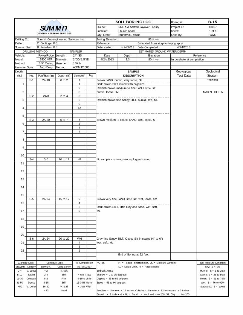
(ft.) No. Pen/Rec (in) Depth (ft) blows/6" N60 DESCRIPTION Test Data StratumS-1 24/18 0 to 2 1 Brown SAND, humid, very loose, SP TOPSOIL
1 1 Dark brown SILT mixed with organics2 Reddish brown medium to fine SAND, little Silt
2 3 humid, loose, SM MARINE DELTAS-2 24/8 2 to 4 3
3 6 Reddish brown fine Sandy SILT, humid, stiff, ML9
4 12
5S-3 24/20 5 to 7 4 Brown medium to coarse SAND, wet, loose, SP
6 34
7 4
8
9
10S-4 0/0 10 to 12 NA No sample - running sands plugged casing
24" SS2"OD/1.5"ID140 lbASTM D1586
GEOENGINEERING SERVICES
SUMMIT
11
12
13
14
15S-5 24/24 15 to 17 2 Brown very fine SAND, little Silt, wet, loose, SM
16 42 Dark brown SILT, little Clay and Sand, wet, soft,
17 2 ML
18
19
20S-6 24/24 20 to 22 WH Gray fine Sandy SILT, Clayey Silt in seams (4" to 6")
21 4 wet, soft, ML3
22 1End of Boring at 22 feet
Granular Soils Cohesive Soils NOTES: PP = Pocket Penetrometer, MC = Moisture Content Soil Moisture Condition
Blows/ft. Density Blows/ft. Consistency LL = Liquid Limit, PI = Plastic Index Dry: S = 0%
0-4 V. Loose <2 V. soft Bedrock Joints Humid: S = 1 to 25%
5-10 Loose 2-4 Soft Shallow = 0 to 35 degrees Damp: S = 26 to 50%
11-30 Compact 5-8 Firm Dipping = 35 to 55 degrees Moist: S = 51 to 75%
31-50 Dense 9-15 Stiff Steep = 55 to 90 degrees Wet: S = 76 to 99%
>50 V. Dense 16-30 V. Stiff Saturated: S = 100%
>30 Hard Boulders = diameter > 12 inches, Cobbles = diameter < 12 inches and > 3 inchesGravel = < 3 inch and > No 4, Sand = < No 4 and >No 200, Silt/Clay = < No 200
< 5% Trace
5-15% Little
15-30% Some
> 30% With
% Composition
ASTM D2487
SOIL BORING LOG Boring #: B-16Project: NNEPRA Amtrak Layover Facility Project #: 13057Location: Church Road Sheet: 1 of 1City, State: Brunswick, Maine Chkd by: CWC
Drilling Co: Summit Geoengineering Services, Inc. Boring Elevation: 84 ft +/-Driller: C. Coolidge, P.E. Reference: Estimated from siteplan topographySummit Staff: B. Peterlein, P.E. Date started: 4/24/2013 Date Completed: 4/24/2013
DRILLING METHOD SAMPLER ESTIMATED GROUND WATER DEPTHVehicle: PowerProbe Length: Date Depth Elevation ReferenceModel: 9500 VTR Diameter: 4/24/2013 4.1 80 ft +/- Groundwater well measurementMethod: 3.5" Casing Hammer: 4/26/2013 4.4 80 ft +/- Groundwater well measurementHammer Style: Auto Drop Method:Depth SAMPLE Geological/ Geological
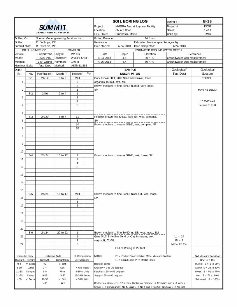
(ft.) No. Pen/Rec (in) Depth (ft) blows/6" N60 DESCRIPTION Test Data StratumS-1 24/12 0 to 2 WH Dark brown SILT, little Sand and Gravel, trace TOPSOIL
1 2 organics, humid, soft, ML3 Brown medium to fine SAND, humid, very loose,
2 1 SP MARINE DELTAS-2 24/6 2 to 4 1
3 24 1" PVC Well
4 3 Screen 3' to 8'
5S-3 24/20 5 to 7 11 Reddish brown fine SAND, little Silt, wet, compact,
6 8 SM10 Brown medium to coarse SAND, wet, compact, SP
7 10
8
9
10S-4 24/24 10 to 12 1 Brown medium to coarse SAND, wet, loose, SP
24" SS2"OD/1.5"ID140 lbASTM D1586
GEOENGINEERING SERVICES
SUMMIT
11 24
12 3
13
14
15S-5 24/24 15 to 17 WH Brown medium to fine SAND, trace Silt, wet, loose,
16 2 SM3
17 3
18
19
20S-6 24/24 20 to 22 1 Brown medium to fine SAND, tr. Silt, wet, loose, SM
21 1 Gray SILT, little fine Sand or Clay in seams, wet, LL = 241 very soft, CL-ML PI = 7
22 3 MC = 26.1%End of Boring at 22 feet
Granular Soils Cohesive Soils NOTES: PP = Pocket Penetrometer, MC = Moisture Content Soil Moisture Condition
Blows/ft. Density Blows/ft. Consistency LL = Liquid Limit, PI = Plastic Index Dry: S = 0%
0-4 V. Loose <2 V. soft Bedrock Joints Humid: S = 1 to 25%
5-10 Loose 2-4 Soft Shallow = 0 to 35 degrees Damp: S = 26 to 50%
11-30 Compact 5-8 Firm Dipping = 35 to 55 degrees Moist: S = 51 to 75%
31-50 Dense 9-15 Stiff Steep = 55 to 90 degrees Wet: S = 76 to 99%
>50 V. Dense 16-30 V. Stiff Saturated: S = 100%
>30 Hard Boulders = diameter > 12 inches, Cobbles = diameter < 12 inches and > 3 inchesGravel = < 3 inch and > No 4, Sand = < No 4 and >No 200, Silt/Clay = < No 200
< 5% Trace
5-15% Little
15-30% Some
> 30% With
% Composition
ASTM D2487
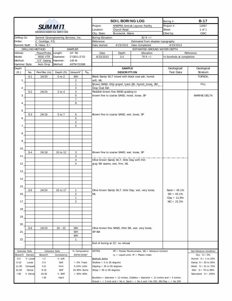
SOIL BORING LOG Boring #: B-17Project: NNEPRA Amtrak Layover Facility Project #: 13057Location: Church Road Sheet: 1 of 1City, State: Brunswick, Maine Chkd by: CWC
Drilling Co: Summit Geoengineering Services, Inc. Boring Elevation: 82 ft +/-Driller: C. Coolidge, P.E. Reference: Estimated from siteplan topographySummit Staff: B. Haiss, E.I. Date started: 4/23/2013 Date Completed: 4/23/2013
DRILLING METHOD SAMPLER ESTIMATED GROUND WATER DEPTHVehicle: PowerProbe Length: Date Depth Elevation ReferenceModel: 9500 VTR Diameter: 4/23/2013 3.4 79 ft +/- In borehole at completionMethod: 3.5" Casing Hammer:Hammer Style: Auto Drop Method:Depth SAMPLE Geological/ Geological
(ft.) No. Pen/Rec (in) Depth (ft) blows/6" N60 DESCRIPTION Test Data StratumS-1 24/20 0 to 2 WH Black Sandy SILT mixed with black coal ash, humid, TOPSOIL
1 2 soft, ML1 Brown SAND, little gravel, trace Silt, humid, loose, SM FILL
2 3 Gray Coal AshS-2 24/24 2 to 4 3 Reddish-brown fine SAND grading to
3 5 brown fine to coarse SAND, moist, loose, SP MARINE DELTA7
4 8
5S-3 24/16 5 to 7 6 Brown fine to coarse SAND, wet, loose, SP
6 54
7 5
8
9
10S-4 24/18 10 to 12 3 Brown fine to coarse SAND, wet, loose, SP
24" SS2"OD/1.5"ID140 lbASTM D1586
GEOENGINEERING SERVICES
SUMMIT
11 34 Olive brown Sandy SILT, little Clay with thin
12 4 gray Silt seams, wet, firm, ML
13
14
15S-5 24/24 15 to 17 1 Olive brown Sandy SILT, little Clay, wet, very loose, Sand = 45.1%
16 2 ML Silt = 43.1%1 Clay = 11.8%
17 2 MC = 22.2%
18
19
20S-6 24/24 20 - 22 WH Olive brown fine SAND, little Silt, wet, very loose,
21 WH SP-SMWH
22 1End of boring at 22', no refusal
Granular Soils Cohesive Soils NOTES: PP = Pocket Penetrometer, MC = Moisture Content Soil Moisture Condition
Blows/ft. Density Blows/ft. Consistency LL = Liquid Limit, PI = Plastic Index Dry: S = 0%
0-4 V. Loose <2 V. soft Bedrock Joints Humid: S = 1 to 25%
5-10 Loose 2-4 Soft Shallow = 0 to 35 degrees Damp: S = 26 to 50%
11-30 Compact 5-8 Firm Dipping = 35 to 55 degrees Moist: S = 51 to 75%
31-50 Dense 9-15 Stiff Steep = 55 to 90 degrees Wet: S = 76 to 99%
>50 V. Dense 16-30 V. Stiff Saturated: S = 100%
>30 Hard Boulders = diameter > 12 inches, Cobbles = diameter < 12 inches and > 3 inchesGravel = < 3 inch and > No 4, Sand = < No 4 and >No 200, Silt/Clay = < No 200
% Composition
ASTM D2487
< 5% Trace
5-15% Little
15-30% Some
> 30% With

SOIL BORING LOG Boring #: B-18Project: NNEPRA Amtrak Layover Facility Project #: 13057Location: Church Road Sheet: 1 of 1City, State: Brunswick, Maine Chkd by: CWC
Drilling Co: Summit Geoengineering Services, Inc. Boring Elevation: 82 ft +/-Driller: C. Coolidge, P.E. Reference: Estimated from siteplan topographySummit Staff: B. Haiss, E.I. Date started: 4/23/2013 Date Completed: 4/23/2013
DRILLING METHOD SAMPLER ESTIMATED GROUND WATER DEPTHVehicle: PowerProbe Length: Date Depth Elevation ReferenceModel: 9500 VTR Diameter: 4/23/2013 3.7 78 ft +/- In borehole at completionMethod: 3.5" Casing Hammer:Hammer Style: Auto Drop Method:Depth SAMPLE Geological/ Geological
(ft.) No. Pen/Rec (in) Depth (ft) blows/6" N60 DESCRIPTION Test Data StratumS-1 24/18 0 to 2 1 Black Silty SAND mixed with coal ash, humid, loose,
1 1 SM FILL3
2 2S-2 24/24 2 to 4 1 Reddish-brown fine SAND grading to
3 3 brown fine to coarse SAND, moist, loose, SP MARINE DELTA6
4 11
5S-3 24/16 5 to 7 8 Brown fine to coarse SAND, wet, compact, SP
6 87
7 8
8
9
10S-4 24/24 10 to 12 2 Brown fine to coarse SAND, wet, loose, SP
24" SS2"OD/1.5"ID140 lbASTM D1586
GEOENGINEERING SERVICES
SUMMIT
11 33
12 5 Olive brown Sandy SILT, little Clay with thingray Silt seams, wet, firm, ML
13
14
15S-5 24/24 15 to 17 WH Gray Sandy SILT, little Clay, wet, very loose, ML Sand = 31.0%
16 WH Silt = 46.5%2 Clay = 15.5%
17 2 MC = 23.7%
18
19
20S-6 24/24 20 - 22 1 Gray Sandy SILT, little Clay, wet, very loose, ML Sand = 36.0%
21 1 Silt = 48.5%2 Clay = 12.5%
22 3 MC = 22.7%End of boring at 22', no refusal
Granular Soils Cohesive Soils NOTES: PP = Pocket Penetrometer, MC = Moisture Content Soil Moisture Condition
Blows/ft. Density Blows/ft. Consistency LL = Liquid Limit, PI = Plastic Index Dry: S = 0%
0-4 V. Loose <2 V. soft Bedrock Joints Humid: S = 1 to 25%
5-10 Loose 2-4 Soft Shallow = 0 to 35 degrees Damp: S = 26 to 50%
11-30 Compact 5-8 Firm Dipping = 35 to 55 degrees Moist: S = 51 to 75%
31-50 Dense 9-15 Stiff Steep = 55 to 90 degrees Wet: S = 76 to 99%
>50 V. Dense 16-30 V. Stiff Saturated: S = 100%
>30 Hard Boulders = diameter > 12 inches, Cobbles = diameter < 12 inches and > 3 inchesGravel = < 3 inch and > No 4, Sand = < No 4 and >No 200, Silt/Clay = < No 200
% Composition
ASTM D2487
< 5% Trace
5-15% Little
15-30% Some
> 30% With

SOIL BORING LOG Boring #: B-21Project: NNEPRA Amtrak Layover Facility Project #: 13057Location: Church Road Sheet: 1 of 1City, State: Brunswick, Maine Chkd by: CWC
Drilling Co: Summit Geoengineering Services, Inc. Boring Elevation: 84 ft +/-Driller: C. Coolidge, P.E. Reference: Estimated from siteplan topographySummit Staff: B. Peterlein, P.E. Date started: 4/24/2013 Date Completed: 4/24/2013
DRILLING METHOD SAMPLER ESTIMATED GROUND WATER DEPTHVehicle: PowerProbe Length: Date Depth Elevation ReferenceModel: 9500 VTR Diameter: 4/24/2013 4.7 79 ft +/- In borehole at completionMethod: 3.5" Casing Hammer:Hammer Style: Auto Drop Method:Depth SAMPLE Geological/ Geological
(ft.) No. Pen/Rec (in) Depth (ft) blows/6" N60 DESCRIPTION Test Data StratumS-1 24/18 0 to 2 1 Dark brown Sandy SILT, trace organics and coal TOPSOIL
1 3 ash, humid, soft, ML4 Brown SAND, humid, compact, SW
2 6 MARINE DELTAS-2 24/24 2 to 4 4 Brwon medium to coarse SAND, mottled in seams,
3 3 loose, SP2
4 2
5S-3 24/24 5 to 7 12 Brown medium to fine SAND, trace Silt, wet,
6 14 compact, SM9
7 8
8
9
10S-4 24/24 10 to 12 1 Brown medium to fine SAND, wet, loose, SP
24" SS2"OD/1.5"ID140 lbASTM D1586
GEOENGINEERING SERVICES
SUMMIT
11 34
12 4End of Boring at 12 feet
13
14
15
16
17
18
19
20
21
22
Granular Soils Cohesive Soils NOTES: PP = Pocket Penetrometer, MC = Moisture Content Soil Moisture Condition
Blows/ft. Density Blows/ft. Consistency LL = Liquid Limit, PI = Plastic Index Dry: S = 0%
0-4 V. Loose <2 V. soft Bedrock Joints Humid: S = 1 to 25%
5-10 Loose 2-4 Soft Shallow = 0 to 35 degrees Damp: S = 26 to 50%
11-30 Compact 5-8 Firm Dipping = 35 to 55 degrees Moist: S = 51 to 75%
31-50 Dense 9-15 Stiff Steep = 55 to 90 degrees Wet: S = 76 to 99%
>50 V. Dense 16-30 V. Stiff Saturated: S = 100%
>30 Hard Boulders = diameter > 12 inches, Cobbles = diameter < 12 inches and > 3 inchesGravel = < 3 inch and > No 4, Sand = < No 4 and >No 200, Silt/Clay = < No 200
< 5% Trace
5-15% Little
15-30% Some
> 30% With
% Composition
ASTM D2487
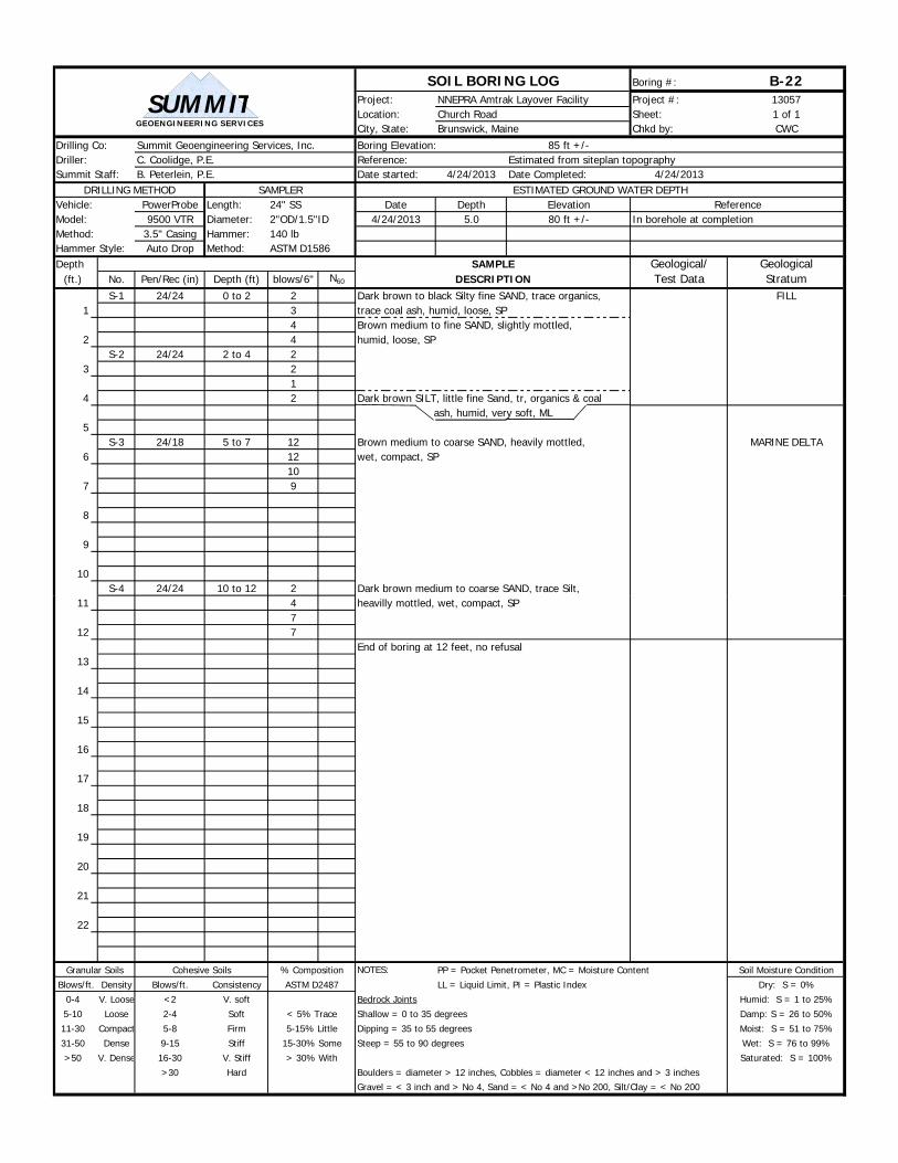
SOIL BORING LOG Boring #: B-22Project: NNEPRA Amtrak Layover Facility Project #: 13057Location: Church Road Sheet: 1 of 1City, State: Brunswick, Maine Chkd by: CWC
Drilling Co: Summit Geoengineering Services, Inc. Boring Elevation: 85 ft +/-Driller: C. Coolidge, P.E. Reference: Estimated from siteplan topographySummit Staff: B. Peterlein, P.E. Date started: 4/24/2013 Date Completed: 4/24/2013
DRILLING METHOD SAMPLER ESTIMATED GROUND WATER DEPTHVehicle: PowerProbe Length: Date Depth Elevation ReferenceModel: 9500 VTR Diameter: 4/24/2013 5.0 80 ft +/- In borehole at completionMethod: 3.5" Casing Hammer:Hammer Style: Auto Drop Method:Depth SAMPLE Geological/ Geological
(ft.) No. Pen/Rec (in) Depth (ft) blows/6" N60 DESCRIPTION Test Data StratumS-1 24/24 0 to 2 2 Dark brown to black Silty fine SAND, trace organics, FILL
1 3 trace coal ash, humid, loose, SP4 Brown medium to fine SAND, slightly mottled,
2 4 humid, loose, SPS-2 24/24 2 to 4 2
3 21
4 2 Dark brown SILT, little fine Sand, tr, organics & coalash, humid, very soft, ML
5S-3 24/18 5 to 7 12 Brown medium to coarse SAND, heavily mottled, MARINE DELTA
6 12 wet, compact, SP10
7 9
8
9
10S-4 24/24 10 to 12 2 Dark brown medium to coarse SAND, trace Silt,
24" SS2"OD/1.5"ID140 lbASTM D1586
GEOENGINEERING SERVICES
SUMMIT
11 4 heavilly mottled, wet, compact, SP7
12 7End of boring at 12 feet, no refusal
13
14
15
16
17
18
19
20
21
22
Granular Soils Cohesive Soils NOTES: PP = Pocket Penetrometer, MC = Moisture Content Soil Moisture Condition
Blows/ft. Density Blows/ft. Consistency LL = Liquid Limit, PI = Plastic Index Dry: S = 0%
0-4 V. Loose <2 V. soft Bedrock Joints Humid: S = 1 to 25%
5-10 Loose 2-4 Soft Shallow = 0 to 35 degrees Damp: S = 26 to 50%
11-30 Compact 5-8 Firm Dipping = 35 to 55 degrees Moist: S = 51 to 75%
31-50 Dense 9-15 Stiff Steep = 55 to 90 degrees Wet: S = 76 to 99%
>50 V. Dense 16-30 V. Stiff Saturated: S = 100%
>30 Hard Boulders = diameter > 12 inches, Cobbles = diameter < 12 inches and > 3 inchesGravel = < 3 inch and > No 4, Sand = < No 4 and >No 200, Silt/Clay = < No 200
< 5% Trace
5-15% Little
15-30% Some
> 30% With
% Composition
ASTM D2487

SOIL BORING LOG Boring #: B-23Project: NNEPRA Amtrak Layover Facility Project #: 13057Location: Church Road Sheet: 1 of 1City, State: Brunswick, Maine Chkd by: CWC
Drilling Co: Summit Geoengineering Services, Inc. Boring Elevation: 86 ft +/-Driller: C. Coolidge, P.E. Reference: Estimated from siteplan topographySummit Staff: B. Peterlein, P.E. Date started: 4/24/2013 Date Completed: 4/24/2013
DRILLING METHOD SAMPLER ESTIMATED GROUND WATER DEPTHVehicle: PowerProbe Length: Date Depth Elevation ReferenceModel: 9500 VTR Diameter: 4/24/2013 6.0 80 ft +/- In borehole at completionMethod: 3.5" Casing Hammer:Hammer Style: Auto Drop Method:Depth SAMPLE Geological/ Geological
(ft.) No. Pen/Rec (in) Depth (ft) blows/6" N60 DESCRIPTION Test Data StratumS-1 24/20 0 to 2 1 Dark brown Sandy SILT, rootlets, humid, ML TOPSOIL
1 2 Black Silty SAND, trace coal ash, humid, loose, SM FILL3 Brown medium to fine SAND, trace Silt, slightly
2 3 mottled, humid loose, SM MARINE DELTAS-2 24/24 2 to 4 3 Reddish-brown Silty fine SAND, mottled, humid,
3 3 loose, SM4
4 5
5S-3 24/18 5 to 7 6
6 6 Olive-brown fine Sandy SILT, wet, compact, ML5
7 6 Brown medium to coarse SAND, wet, compact, SP
8
9
10S-4 24/24 10 to 12 1 Brown medium to coarse SAND, wet, loose, SP
24" SS2"OD/1.5"ID140 lbASTM D1586
GEOENGINEERING SERVICES
SUMMIT
11 36
12 7End of boring at 12 feet, no refusal
13
14
15
16
17
18
19
20
21
22
Granular Soils Cohesive Soils NOTES: PP = Pocket Penetrometer, MC = Moisture Content Soil Moisture Condition
Blows/ft. Density Blows/ft. Consistency LL = Liquid Limit, PI = Plastic Index Dry: S = 0%
0-4 V. Loose <2 V. soft Bedrock Joints Humid: S = 1 to 25%
5-10 Loose 2-4 Soft Shallow = 0 to 35 degrees Damp: S = 26 to 50%
11-30 Compact 5-8 Firm Dipping = 35 to 55 degrees Moist: S = 51 to 75%
31-50 Dense 9-15 Stiff Steep = 55 to 90 degrees Wet: S = 76 to 99%
>50 V. Dense 16-30 V. Stiff Saturated: S = 100%
>30 Hard Boulders = diameter > 12 inches, Cobbles = diameter < 12 inches and > 3 inchesGravel = < 3 inch and > No 4, Sand = < No 4 and >No 200, Silt/Clay = < No 200
< 5% Trace
5-15% Little
15-30% Some
> 30% With
% Composition
ASTM D2487
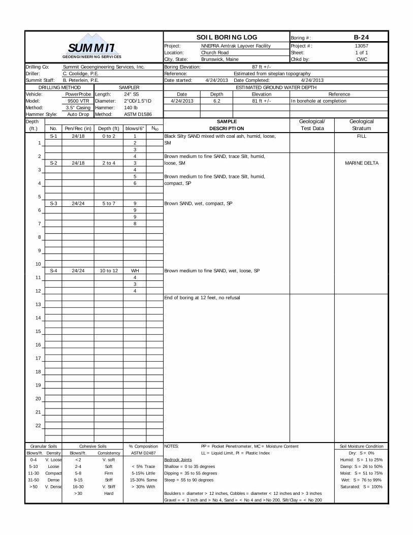
SOIL BORING LOG Boring #: B-24Project: NNEPRA Amtrak Layover Facility Project #: 13057Location: Church Road Sheet: 1 of 1City, State: Brunswick, Maine Chkd by: CWC
Drilling Co: Summit Geoengineering Services, Inc. Boring Elevation: 87 ft +/-Driller: C. Coolidge, P.E. Reference: Estimated from siteplan topographySummit Staff: B. Peterlein, P.E. Date started: 4/24/2013 Date Completed: 4/24/2013
DRILLING METHOD SAMPLER ESTIMATED GROUND WATER DEPTHVehicle: PowerProbe Length: Date Depth Elevation ReferenceModel: 9500 VTR Diameter: 4/24/2013 6.2 81 ft +/- In borehole at completionMethod: 3.5" Casing Hammer:Hammer Style: Auto Drop Method:Depth SAMPLE Geological/ Geological
(ft.) No. Pen/Rec (in) Depth (ft) blows/6" N60 DESCRIPTION Test Data StratumS-1 24/18 0 to 2 1 Black Silty SAND mixed with coal ash, humid, loose, FILL
1 2 SM3
2 4 Brown medium to fine SAND, trace Silt, humid,S-2 24/18 2 to 4 3 loose, SM MARINE DELTA
3 45 Brown medium to fine SAND, trace Silt, humid,
4 6 compact, SP
5S-3 24/24 5 to 7 9 Brown SAND, wet, compact, SP
6 99
7 8
8
9
10S-4 24/24 10 to 12 WH Brown medium to fine SAND, wet, loose, SP
24" SS2"OD/1.5"ID140 lbASTM D1586
GEOENGINEERING SERVICES
SUMMIT
11 43
12 4End of boring at 12 feet, no refusal
13
14
15
16
17
18
19
20
21
22
Granular Soils Cohesive Soils NOTES: PP = Pocket Penetrometer, MC = Moisture Content Soil Moisture Condition
Blows/ft. Density Blows/ft. Consistency LL = Liquid Limit, PI = Plastic Index Dry: S = 0%
0-4 V. Loose <2 V. soft Bedrock Joints Humid: S = 1 to 25%
5-10 Loose 2-4 Soft Shallow = 0 to 35 degrees Damp: S = 26 to 50%
11-30 Compact 5-8 Firm Dipping = 35 to 55 degrees Moist: S = 51 to 75%
31-50 Dense 9-15 Stiff Steep = 55 to 90 degrees Wet: S = 76 to 99%
>50 V. Dense 16-30 V. Stiff Saturated: S = 100%
>30 Hard Boulders = diameter > 12 inches, Cobbles = diameter < 12 inches and > 3 inchesGravel = < 3 inch and > No 4, Sand = < No 4 and >No 200, Silt/Clay = < No 200
< 5% Trace
5-15% Little
15-30% Some
> 30% With
% Composition
ASTM D2487
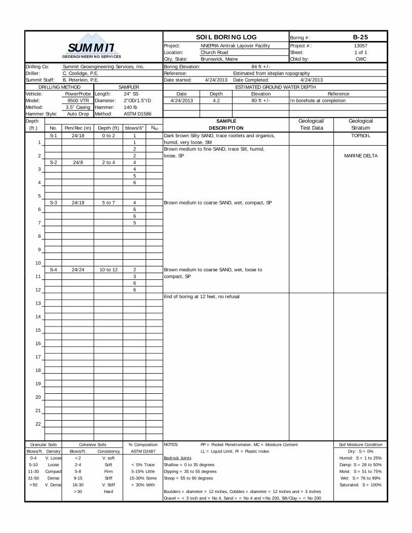
SOIL BORING LOG Boring #: B-25Project: NNEPRA Amtrak Layover Facility Project #: 13057Location: Church Road Sheet: 1 of 1City, State: Brunswick, Maine Chkd by: CWC
Drilling Co: Summit Geoengineering Services, Inc. Boring Elevation: 84 ft +/-Driller: C. Coolidge, P.E. Reference: Estimated from siteplan topographySummit Staff: B. Peterlein, P.E. Date started: 4/24/2013 Date Completed: 4/24/2013
DRILLING METHOD SAMPLER ESTIMATED GROUND WATER DEPTHVehicle: PowerProbe Length: Date Depth Elevation ReferenceModel: 9500 VTR Diameter: 4/24/2013 4.2 80 ft +/- In borehole at completionMethod: 3.5" Casing Hammer:Hammer Style: Auto Drop Method:Depth SAMPLE Geological/ Geological
(ft.) No. Pen/Rec (in) Depth (ft) blows/6" N60 DESCRIPTION Test Data StratumS-1 24/18 0 to 2 1 Dark brown Silty SAND, trace rootlets and organics, TOPSOIL
1 1 humid, very loose, SM2 Brown medium to fine SAND, trace Silt, humid,
2 2 loose, SP MARINE DELTAS-2 24/8 2 to 4 4
3 45
4 6
5S-3 24/18 5 to 7 4 Brown medium to coarse SAND, wet, compact, SP
6 66
7 5
8
9
10S-4 24/24 10 to 12 2 Brown medium to coarse SAND, wet, loose to
24" SS2"OD/1.5"ID140 lbASTM D1586
GEOENGINEERING SERVICES
SUMMIT
11 3 compact, SP6
12 6End of boring at 12 feet, no refusal
13
14
15
16
17
18
19
20
21
22
Granular Soils Cohesive Soils NOTES: PP = Pocket Penetrometer, MC = Moisture Content Soil Moisture Condition
Blows/ft. Density Blows/ft. Consistency LL = Liquid Limit, PI = Plastic Index Dry: S = 0%
0-4 V. Loose <2 V. soft Bedrock Joints Humid: S = 1 to 25%
5-10 Loose 2-4 Soft Shallow = 0 to 35 degrees Damp: S = 26 to 50%
11-30 Compact 5-8 Firm Dipping = 35 to 55 degrees Moist: S = 51 to 75%
31-50 Dense 9-15 Stiff Steep = 55 to 90 degrees Wet: S = 76 to 99%
>50 V. Dense 16-30 V. Stiff Saturated: S = 100%
>30 Hard Boulders = diameter > 12 inches, Cobbles = diameter < 12 inches and > 3 inchesGravel = < 3 inch and > No 4, Sand = < No 4 and >No 200, Silt/Clay = < No 200
< 5% Trace
5-15% Little
15-30% Some
> 30% With
% Composition
ASTM D2487
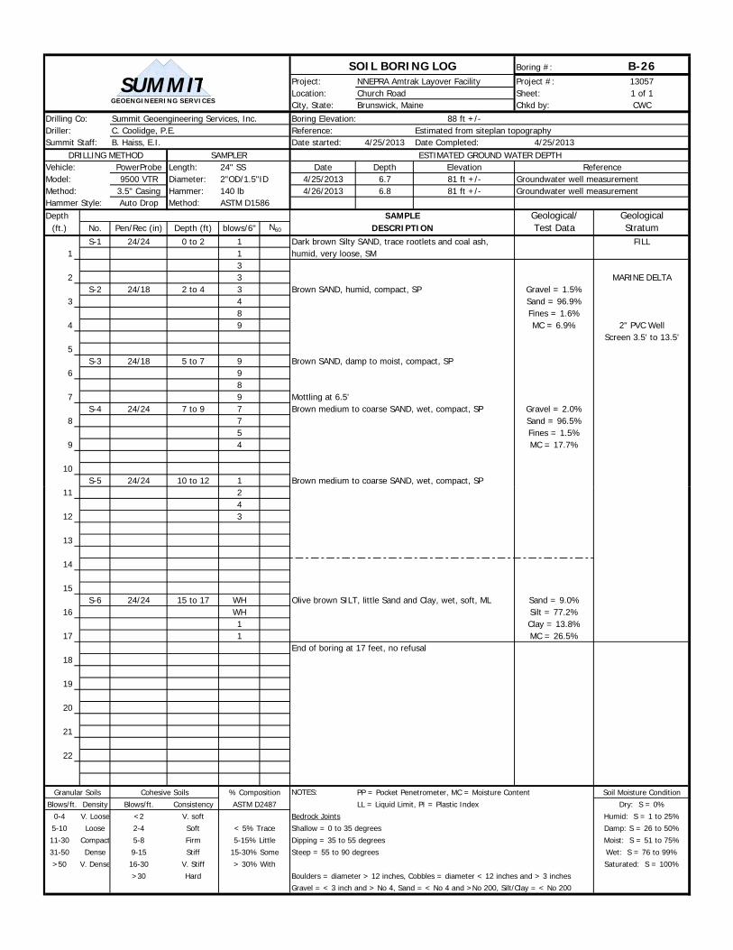
SOIL BORING LOG Boring #: B-26Project: NNEPRA Amtrak Layover Facility Project #: 13057Location: Church Road Sheet: 1 of 1City, State: Brunswick, Maine Chkd by: CWC
Drilling Co: Summit Geoengineering Services, Inc. Boring Elevation: 88 ft +/-Driller: C. Coolidge, P.E. Reference: Estimated from siteplan topographySummit Staff: B. Haiss, E.I. Date started: 4/25/2013 Date Completed: 4/25/2013
DRILLING METHOD SAMPLER ESTIMATED GROUND WATER DEPTHVehicle: PowerProbe Length: Date Depth Elevation ReferenceModel: 9500 VTR Diameter: 4/25/2013 6.7 81 ft +/- Groundwater well measurementMethod: 3.5" Casing Hammer: 4/26/2013 6.8 81 ft +/- Groundwater well measurementHammer Style: Auto Drop Method:Depth SAMPLE Geological/ Geological
(ft.) No. Pen/Rec (in) Depth (ft) blows/6" N60 DESCRIPTION Test Data StratumS-1 24/24 0 to 2 1 Dark brown Silty SAND, trace rootlets and coal ash, FILL
1 1 humid, very loose, SM3
2 3 MARINE DELTAS-2 24/18 2 to 4 3 Brown SAND, humid, compact, SP Gravel = 1.5%
3 4 Sand = 96.9%8 Fines = 1.6%
4 9 MC = 6.9% 2" PVC WellScreen 3.5' to 13.5'
5S-3 24/18 5 to 7 9 Brown SAND, damp to moist, compact, SP
6 98
7 9 Mottling at 6.5'S-4 24/24 7 to 9 7 Brown medium to coarse SAND, wet, compact, SP Gravel = 2.0%
8 7 Sand = 96.5%5 Fines = 1.5%
9 4 MC = 17.7%
10S-5 24/24 10 to 12 1 Brown medium to coarse SAND, wet, compact, SP
24" SS2"OD/1.5"ID140 lbASTM D1586
GEOENGINEERING SERVICES
SUMMIT
11 24
12 3
13
14
15S-6 24/24 15 to 17 WH Olive brown SILT, little Sand and Clay, wet, soft, ML Sand = 9.0%
16 WH Silt = 77.2%1 Clay = 13.8%
17 1 MC = 26.5%End of boring at 17 feet, no refusal
18
19
20
21
22
Granular Soils Cohesive Soils NOTES: PP = Pocket Penetrometer, MC = Moisture Content Soil Moisture Condition
Blows/ft. Density Blows/ft. Consistency LL = Liquid Limit, PI = Plastic Index Dry: S = 0%
0-4 V. Loose <2 V. soft Bedrock Joints Humid: S = 1 to 25%
5-10 Loose 2-4 Soft Shallow = 0 to 35 degrees Damp: S = 26 to 50%
11-30 Compact 5-8 Firm Dipping = 35 to 55 degrees Moist: S = 51 to 75%
31-50 Dense 9-15 Stiff Steep = 55 to 90 degrees Wet: S = 76 to 99%
>50 V. Dense 16-30 V. Stiff Saturated: S = 100%
>30 Hard Boulders = diameter > 12 inches, Cobbles = diameter < 12 inches and > 3 inchesGravel = < 3 inch and > No 4, Sand = < No 4 and >No 200, Silt/Clay = < No 200
% Composition
ASTM D2487
< 5% Trace
5-15% Little
15-30% Some
> 30% With

SOIL BORING LOG Boring #: B-27Project: NNEPRA Amtrak Layover Facility Project #: 13057Location: Church Road Sheet: 1 of 1City, State: Brunswick, Maine Chkd by: CWC
Drilling Co: Summit Geoengineering Services, Inc. Boring Elevation: 87 ft +/-Driller: C. Coolidge, P.E. Reference: Estimated from siteplan topographySummit Staff: B. Peterlein, P.E. Date started: 4/24/2013 Date Completed: 4/24/2013
DRILLING METHOD SAMPLER ESTIMATED GROUND WATER DEPTHVehicle: PowerProbe Length: Date Depth Elevation ReferenceModel: 9500 VTR Diameter: 4/24/2013 7.4 80 ft +/- In borehole at completionMethod: 3.5" Casing Hammer:Hammer Style: Auto Drop Method:Depth SAMPLE Geological/ Geological
(ft.) No. Pen/Rec (in) Depth (ft) blows/6" N60 DESCRIPTION Test Data StratumS-1 24/24 0 to 2 1 Black Sandy SILT mixed with coal ash, trace rootlets,
1 2 humid, very soft, ML FILL2
2 1 Brown medium to fine SAND, humid, very loose, SPS-2 24/24 2 to 4 2 MARINE DELTA
3 22
4 3
5S-3 24/24 5 to 7 5 Brown SAND, humid, compact, SP
6 66
7 6
8
9
10S-4 24/24 10 to 12 1 Brown medium to fine SAND, wet, very loose, SP
24" SS2"OD/1.5"ID140 lbASTM D1586
GEOENGINEERING SERVICES
SUMMIT
11 22
12 2End of boring at 12 feet, no refusal
13
14
15
16
17
18
19
20
21
22
Granular Soils Cohesive Soils NOTES: PP = Pocket Penetrometer, MC = Moisture Content Soil Moisture Condition
Blows/ft. Density Blows/ft. Consistency LL = Liquid Limit, PI = Plastic Index Dry: S = 0%
0-4 V. Loose <2 V. soft Bedrock Joints Humid: S = 1 to 25%
5-10 Loose 2-4 Soft Shallow = 0 to 35 degrees Damp: S = 26 to 50%
11-30 Compact 5-8 Firm Dipping = 35 to 55 degrees Moist: S = 51 to 75%
31-50 Dense 9-15 Stiff Steep = 55 to 90 degrees Wet: S = 76 to 99%
>50 V. Dense 16-30 V. Stiff Saturated: S = 100%
>30 Hard Boulders = diameter > 12 inches, Cobbles = diameter < 12 inches and > 3 inchesGravel = < 3 inch and > No 4, Sand = < No 4 and >No 200, Silt/Clay = < No 200
< 5% Trace
5-15% Little
15-30% Some
> 30% With
% Composition
ASTM D2487
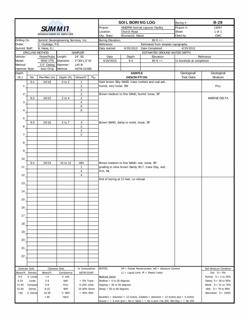
SOIL BORING LOG Boring #: B-28Project: NNEPRA Amtrak Layover Facility Project #: 13057Location: Church Road Sheet: 1 of 1City, State: Brunswick, Maine Chkd by: CWC
Drilling Co: Summit Geoengineering Services, Inc. Boring Elevation: 89 ft +/-Driller: C. Coolidge, P.E. Reference: Estimated from siteplan topographySummit Staff: B. Haiss, E.I. Date started: 4/25/2013 Date Completed: 4/25/2013
DRILLING METHOD SAMPLER ESTIMATED GROUND WATER DEPTHVehicle: PowerProbe Length: Date Depth Elevation ReferenceModel: 9500 VTR Diameter: 4/25/2013 9.4 80 ft +/- In borehole at completionMethod: 3.5" Casing Hammer:Hammer Style: Auto Drop Method:Depth SAMPLE Geological/ Geological
(ft.) No. Pen/Rec (in) Depth (ft) blows/6" N60 DESCRIPTION Test Data StratumS-1 24/18 0 to 2 1 Dark brown Silty SAND, trace rootlets and coal ash,
1 2 humid, very loose, SM FILL2
2 2 Brown medium to fine SAND, humid, loose, SPS-2 24/22 2 to 4 2 MARINE DELTA
3 46
4 6
5S-3 24/16 5 to 7 3 Brown SAND, damp to moist, loose, SP
6 22
7 2
8
9
10S-4 24/24 10 to 12 WH Brown medium to fine SAND, wet, loose, SP
24" SS2"OD/1.5"ID140 lbASTM D1586
GEOENGINEERING SERVICES
SUMMIT
11 1 grading to olive brown Sandy SILT, trace Clay, wet,4 firm, ML
12 4End of boring at 12 feet, no refusal
13
14
15
16
17
18
19
20
21
22
Granular Soils Cohesive Soils NOTES: PP = Pocket Penetrometer, MC = Moisture Content Soil Moisture Condition
Blows/ft. Density Blows/ft. Consistency LL = Liquid Limit, PI = Plastic Index Dry: S = 0%
0-4 V. Loose <2 V. soft Bedrock Joints Humid: S = 1 to 25%
5-10 Loose 2-4 Soft Shallow = 0 to 35 degrees Damp: S = 26 to 50%
11-30 Compact 5-8 Firm Dipping = 35 to 55 degrees Moist: S = 51 to 75%
31-50 Dense 9-15 Stiff Steep = 55 to 90 degrees Wet: S = 76 to 99%
>50 V. Dense 16-30 V. Stiff Saturated: S = 100%
>30 Hard Boulders = diameter > 12 inches, Cobbles = diameter < 12 inches and > 3 inchesGravel = < 3 inch and > No 4, Sand = < No 4 and >No 200, Silt/Clay = < No 200
% Composition
ASTM D2487
< 5% Trace
5-15% Little
15-30% Some
> 30% With

CPT Soil Behavior Type Legend (Robertson et al. 1990)
Sensitive, Fine Grained
Organic Soils-Peats
Clays; Clay to Silty Clay
Silt Mixtures; Clayey Silt to Silty Clay
Sand Mixtures; Silty Sand to Sandy Silt
Sands; Clean Sands to Silty Sands
Gravelly Sand to Sand
Very Stiff Sand to Clayey Sand*
Very Stiff Fine Grained**Overconsolidated or Cemented
1
2
3
4
5
6
7
8
9
Zone Soil Behavior Type
Fr = x 100 (%)qt - σvo
fs0.1 1 10
1
10
100
1000
98
7
6
4
3
5
2
1
0.1 1 101
10
100
1000
98
7
6
4
3
5
2
1
Qt=
q t
-σ v
o
σ′vo
-0.6 -0.2 0.2 0.6 1 1.41
100
1000
7
6
12
10
4
3
5
Bq = qt-σvo
Δuqt-σvo
Δu
-0.6 -0.2 0.2 0.6 1 1.41
100
1000
7
6
12
10
4
3
5
Qt=
q t
-σ v
oσ′
vo
Fr = x 100 (%)qt - σvo
fs0.1 1 10
1
10
100
1000
98
7
6
4
3
5
2
1
0.1 1 101
10
100
1000
98
7
6
4
3
5
2
1
Qt=
q t
-σ v
o
σ′vo
Qt=
q t
-σ v
o
σ′vo
-0.6 -0.2 0.2 0.6 1 1.41
100
1000
7
6
12
10
4
3
5
Bq = qt-σvo
Δuqt-σvo
Δu
-0.6 -0.2 0.2 0.6 1 1.41
100
1000
7
6
12
10
4
3
5
Qt=
q t
-σ v
oσ′
voQ
t=
q t
-σ v
oσ′
vo
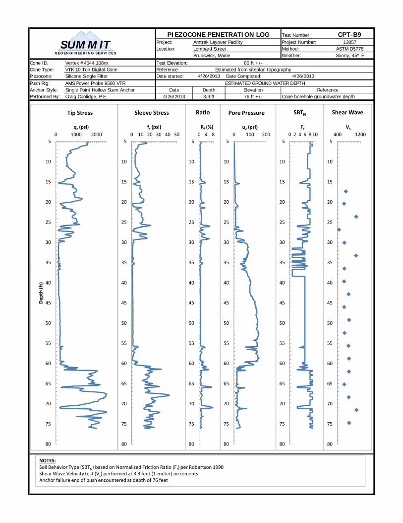
PIEZOCONE PENETRATION LOG Test Number: CPT-B9Project: Amtrak Layover Facility Project Number: 13057Location: Lombard Street Method: ASTM D5778
Brunswick, Maine Weather: Sunny, 45* FCone ID: Vertek #4644.108xx Test Elevation: 80 ft +/-Cone Type: VTK 10 Ton Digital Cone Reference: Estimated from siteplan topographyPiezocone: Silicone Single Filter Date started: 4/26/2013 Date Completed: 4/26/2013Push Rig: AMS Power Probe 9500 VTR ESTIMATED GROUND WATER DEPTHAnchor Style: Single Point Hollow Stem Anchor Date Depth Elevation ReferencePerformed By: Craig Coolidge, P.E. 4/26/2013 3.9 ft 76 ft +/- Cone borehole groundwater depth
5
10
15
20
25
30
35
0 1000 2000
qc (psi)
Tip Stress
5
10
15
20
25
30
35
0 10 20 30 40 50
fs (psi)
Sleeve Stress
5
10
15
20
25
30
35
0 4 8
Rf (%)
Ratio
5
10
15
20
25
30
35
0 100 200
u2 (psi)
Pore Pressure
5
10
15
20
25
30
35
400 1200
Vs
Shear Wave
5
10
15
20
25
30
35
0 2 4 6 8 10
Fr
SBTN
GEO EN GIN EERIN G SERVICES
SUM M IT
40
45
50
55
60
65
70
75
80
Dep
th (ft) 40
45
50
55
60
65
70
75
80
40
45
50
55
60
65
70
75
80
40
45
50
55
60
65
70
75
80
NOTES:Soil Behavior Type (SBTN) based on Normalized Friction Ratio (Fr) per Robertson 1990Shear Wave Velocity test (Vs) performed at 3.3 feet (1‐meter) increments Anchor failure end of push encountered at depth of 76 feet
40
45
50
55
60
65
70
75
80
40
45
50
55
60
65
70
75
80

PIEZOCONE PENETRATION LOG Test Number: CPT-B12Project: Amtrak Layover Facility Project Number: 13057Location: Lombard Street Method: ASTM D5778
Brunswick, Maine Weather: Sunny, 45* FCone ID: Vertek #4644.108xx Test Elevation: 82 ft +/-Cone Type: VTK 10 Ton Digital Cone Reference: Estimated from siteplan topographPiezocone: Silicone Single Filter Date started: 4/26/2013 Date Completed: 4/26/2013Push Rig: AMS Power Probe 9500 VTR ESTIMATED GROUND WATER DEPTHAnchor Style: Single Point Hollow Stem Anchor Date Depth Elevation ReferencePerformed By: Craig Coolidge, P.E. 4/26/2013 3.8 ft 78 ft +/- Cone borehole groundwater depth
5
10
15
20
25
30
35
40
0 1000 2000
qc (psi)
Tip Stress
5
10
15
20
25
30
35
40
0 10 20 30
fs (psi)
Sleeve Stress
5
10
15
20
25
30
35
40
0 4 8
Rf (%)
Ratio
5
10
15
20
25
30
35
40
0 100 200
u2 (psi)
Pore Pressure
5
10
15
20
25
30
35
40
200 1000
Vs
Shear Wave
5
10
15
20
25
30
35
40
0 2 4 6 8 10
Fr
SBTN
GEO EN GIN EERIN G SERVICES
SUM M IT
GEO EN GIN EERIN G SERVICES
SUM M IT
45
50
55
60
65
70
75
80
85
90
95
Dep
th (ft)
45
50
55
60
65
70
75
80
85
90
95
45
50
55
60
65
70
75
80
85
90
95
45
50
55
60
65
70
75
80
85
90
95
NOTES:Soil Behavior Type (SBTN) based on Normalized Friction Ratio (Fr) per Robertson 1990Shear Wave Velocity test (Vs) performed at 3.3 feet (1‐meter) increments Anchor failure end of push encountered at depth of 92 feet
45
50
55
60
65
70
75
80
85
90
95
45
50
55
60
65
70
75
80
85
90
95
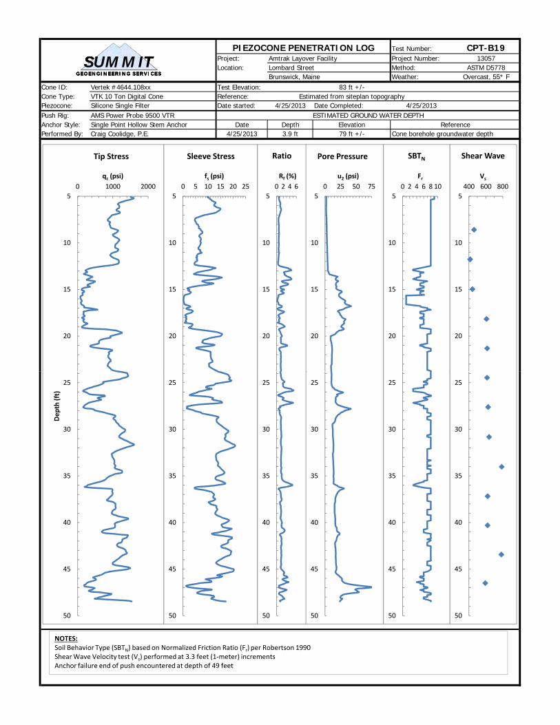
PIEZOCONE PENETRATION LOG Test Number: CPT-B19Project: Amtrak Layover Facility Project Number: 13057Location: Lombard Street Method: ASTM D5778
Brunswick, Maine Weather: Overcast, 55* FCone ID: Vertek #4644.108xx Test Elevation: 83 ft +/-Cone Type: VTK 10 Ton Digital Cone Reference: Estimated from siteplan topographyPiezocone: Silicone Single Filter Date started: 4/25/2013 Date Completed: 4/25/2013Push Rig: AMS Power Probe 9500 VTR ESTIMATED GROUND WATER DEPTHAnchor Style: Single Point Hollow Stem Anchor Date Depth Elevation ReferencePerformed By: Craig Coolidge, P.E. 4/25/2013 3.9 ft 79 ft +/- Cone borehole groundwater depth
5
10
15
20
0 1000 2000
qc (psi)
Tip Stress
5
10
15
20
0 5 10 15 20 25
fs (psi)
Sleeve Stress
5
10
15
20
0 2 4 6
Rf (%)
Ratio
5
10
15
20
0 25 50 75
u2 (psi)
Pore Pressure
5
10
15
20
400 600 800
Vs
Shear Wave
5
10
15
20
0 2 4 6 8 10
Fr
SBTN
GEO EN GIN EERIN G SERVICES
SUM M IT
GEO EN GIN EERIN G SERVICES
SUM M IT
GEO EN GIN EERIN G SERVICES
SUM M IT
25
30
35
40
45
50
Dep
th (ft)
25
30
35
40
45
50
25
30
35
40
45
50
25
30
35
40
45
50
NOTES:Soil Behavior Type (SBTN) based on Normalized Friction Ratio (Fr) per Robertson 1990Shear Wave Velocity test (Vs) performed at 3.3 feet (1‐meter) increments Anchor failure end of push encountered at depth of 49 feet
25
30
35
40
45
50
25
30
35
40
45
50

PIEZOCONE PENETRATION LOG Test Number: CPT-B20Project: Amtrak Layover Facility Project Number: 13057Location: Lombard Street Method: ASTM D5778
Brunswick, Maine Weather: Overcast, 55* FCone ID: Vertek #4644.108xx Test Elevation: 84 ft +/-Cone Type: VTK 10 Ton Digital Cone Reference: Survey located by TKM Land Surveyors, Inc.Piezocone: Silicone Single Filter Date started: 4/25/2013 Date Completed: 4/25/2013Push Rig: AMS Power Probe 9500 VTR ESTIMATED GROUND WATER DEPTHAnchor Style: Single Point Hollow Stem Anchor Date Depth Elevation ReferencePerformed By: Craig Coolidge, P.E. 4/25/2013 3.9 ft 80 ft +/- Cone borehole groundwater depth
5
10
15
20
25
30
0 1000 2000
qc (psi)
Tip Stress
5
10
15
20
25
30
0 10 20 30 40
fs (psi)
Sleeve Stress
5
10
15
20
25
30
0 2 4 6
Rf (%)
Ratio
5
10
15
20
25
30
0 50 100 150
u2 (psi)
Pore Pressure
5
10
15
20
25
30
300 900
Vs
Shear Wave
5
10
15
20
25
30
0 2 4 6 8 10
Fr
SBTN
GEO EN GIN EERIN G SERVICES
SUM M IT
GEO EN GIN EERIN G SERVICES
SUM M IT
GEO EN GIN EERIN G SERVICES
SUM M IT
GEO EN GIN EERIN G SERVICES
SUM M IT
30
35
40
45
50
55
60
65
Dep
th (ft)
30
35
40
45
50
55
60
65
30
35
40
45
50
55
60
65
30
35
40
45
50
55
60
65
NOTES:Soil Behavior Type (SBTN) based on Normalized Friction Ratio (Fr) per Robertson 1990Shear Wave Velocity test (Vs) performed at 3.3 feet (1‐meter) increments Anchor failure end of push encountered at depth of 62 feet
30
35
40
45
50
55
60
65
30
35
40
45
50
55
60
65
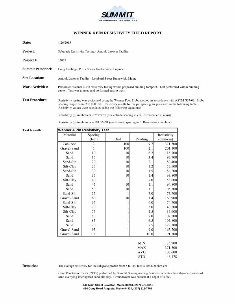
Date: 4/26/2013
Project: Subgrade Resistivity Testing - Amtrak Layover Facility
Project #: 13057
Summit Personnel: Craig Coolidge, P.E. - Senior Geotechnical Engineer
Site Location:
Work Activities:
Test Procedure:
Test Results: Wenner 4 Pin Resistivity TestMaterial Spacing Resistivity
(feet) Dial Reading (ohm-cm)
WENNER 4 PIN RESISTIVITY FIELD REPORT
Performed Wenner 4-Pin resistivity testing within proposed building footprint. Test performed within building center. Test was aligned and performed east to west.
Amtrak Layover Facility - Lombard Street Brunswick, Maine
Resistivity testing was performed using the Wenner Four Probe method in accordance with ASTM G57-06. Probe spacing ranged from 2 to 100 feet. Resistivity results for the pin spacing are presented in the following table. Resistivity values were calculated using the following equations:
Resistivity (p) in ohm-cm = 2*π*a*R (a=electrode spacing in cm, R=resistance in ohms)
Resistivity (p) in ohm-cm = 191.5*a*R (a=electrode spacing in ft, R=resistance in ohms)
GEOENGINEERING SERVICES
SUMMIT
Coal Ash 2 100 9.7 371,500Gravel-Sand 5 100 2.1 201,100
Sand 10 10 6.2 118,700Sand 15 10 3.4 97,700
Sand-Silt 20 10 2.1 80,400Silt-Clay 25 10 1.2 57,500Sand-Silt 30 10 1.5 86,200
Sand 35 10 1.4 93,800Silt-Clay 40 1 7.0 53,600
Sand 45 10 1.1 94,800Sand 50 10 1.1 105,300
Sand-Silt 55 1 7.0 73,700Gravel-Sand 60 10 1.4 160,900
Sand-Silt 65 1 6.0 74,700Silt-Clay 70 1 3.0 40,200Silt-Clay 75 1 2.5 35,900
Sand 80 1 7.0 107,200Sand 85 1 6.5 105,800Sand 90 1 7.5 129,300
Gravel-Sand 95 1 9.0 163,700Gravel-Sand 100 1 10.0 191,500
MIN 35,900MAX 371,500AVG 103,600STD 46,478
Remarks: The average resistivity for the subgrade profile from 5 to 100 feet is 103,600 ohm-cm
Cone Penetration Tests (CPTu) performed by Summit Geoengineering Services indicates the subgrade consists of sand overlying interlayered sand-silt-clay. Groundwater was present at a depth of 4 feet.
640 M i St t L i t M i 04240 (207) 576 3313 640 Main Street Lewiston, Maine 04240, (207) 576-3313434 Cony Road Augusta, Maine 04330, (207) 318-7761
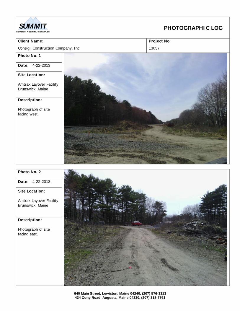
640 Main Street, Lewiston, Maine 04240, (207) 576-3313 434 Cony Road, Augusta, Maine 04330, (207) 318-7761
PHOTOGRAPHIC LOG
Client Name:
Consigli Construction Company, Inc.
Project No.
13057
Photo No. 1 Date: 4-22-2013 Site Location: Amtrak Layover Facility Brunswick, Maine
Description: Photograph of site facing west.
Photo No. 2 Date: 4-22-2013 Site Location: Amtrak Layover Facility Brunswick, Maine Description: Photograph of site facing east.
GEOENGINEERING SERVICES
SUMMIT
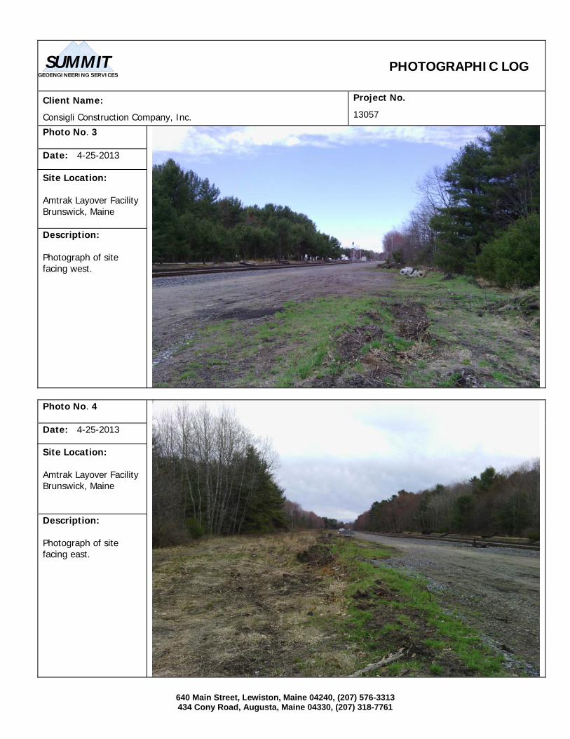
640 Main Street, Lewiston, Maine 04240, (207) 576-3313 434 Cony Road, Augusta, Maine 04330, (207) 318-7761
PHOTOGRAPHIC LOG
Client Name:
Consigli Construction Company, Inc.
Project No.
13057
Photo No. 3 Date: 4-25-2013 Site Location: Amtrak Layover Facility Brunswick, Maine Description: Photograph of site facing west.
Photo No. 4 Date: 4-25-2013 Site Location: Amtrak Layover Facility Brunswick, Maine Description: Photograph of site facing east.
GEOENGINEERING SERVICES
SUMMIT

640 Main Street, Lewiston, Maine 04240, (207) 576-3313 434 Cony Road, Augusta, Maine 04330, (207) 318-7761
PHOTOGRAPHIC LOG
Client Name:
Consigli Construction Company, Inc.
Project No.
13057
Photo No. 5 Date: 4-26-2013 Site Location: Amtrak Layover Facility Brunswick, Maine Description: Photograph of site facing west.
Photo No. 6 Date: 4-26-2013 Site Location: Amtrak Layover Facility Brunswick, Maine Description: Photograph of site facing east.
GEOENGINEERING SERVICES
SUMMIT
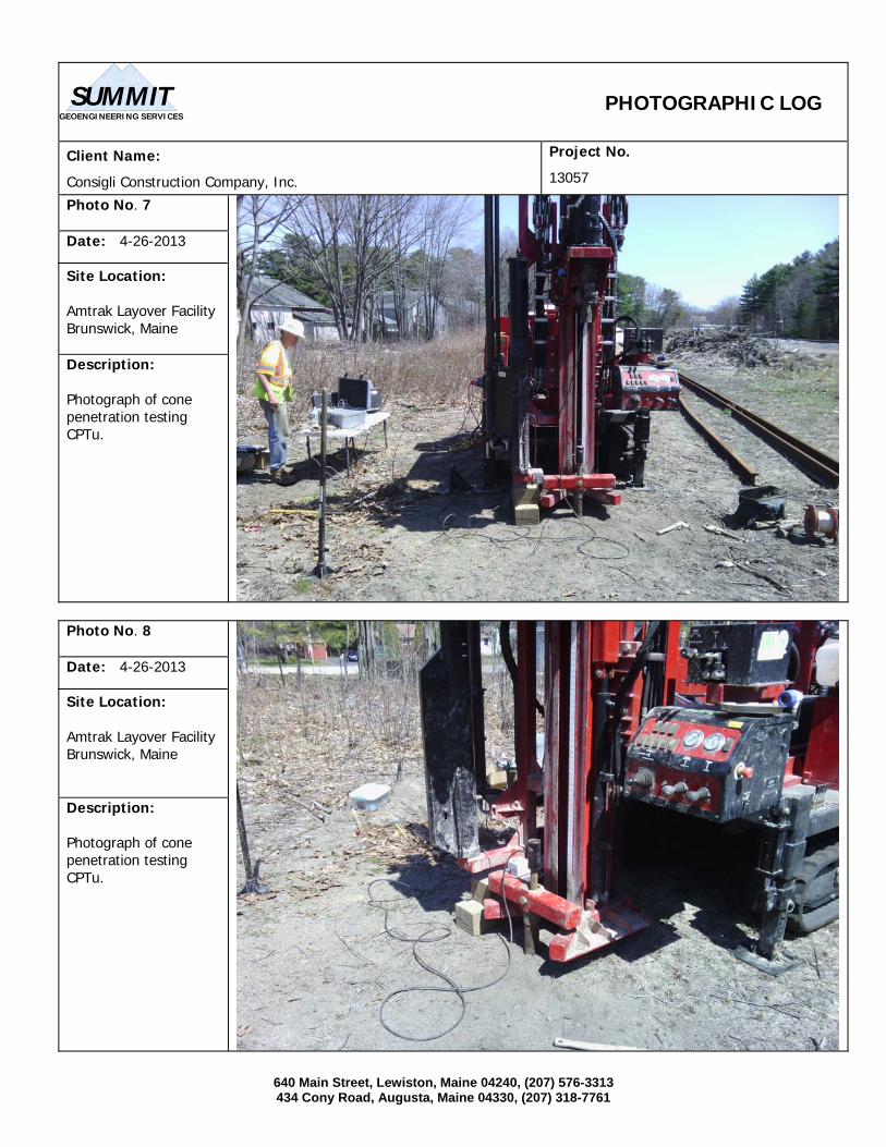
640 Main Street, Lewiston, Maine 04240, (207) 576-3313 434 Cony Road, Augusta, Maine 04330, (207) 318-7761
PHOTOGRAPHIC LOG
Client Name:
Consigli Construction Company, Inc.
Project No.
13057
Photo No. 7 Date: 4-26-2013 Site Location: Amtrak Layover Facility Brunswick, Maine Description: Photograph of cone penetration testing CPTu.
Photo No. 8 Date: 4-26-2013 Site Location: Amtrak Layover Facility Brunswick, Maine Description: Photograph of cone penetration testing CPTu.
GEOENGINEERING SERVICES
SUMMIT
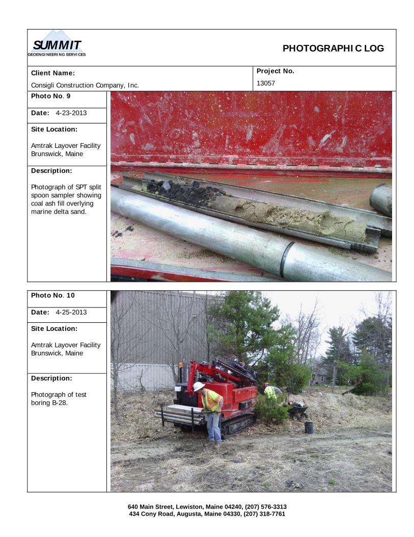
640 Main Street, Lewiston, Maine 04240, (207) 576-3313 434 Cony Road, Augusta, Maine 04330, (207) 318-7761
PHOTOGRAPHIC LOG
Client Name:
Consigli Construction Company, Inc.
Project No.
13057
Photo No. 9 Date: 4-23-2013 Site Location: Amtrak Layover Facility Brunswick, Maine Description: Photograph of SPT split spoon sampler showing coal ash fill overlying marine delta sand.
Photo No. 10 Date: 4-25-2013 Site Location: Amtrak Layover Facility Brunswick, Maine Description: Photograph of test boring B-28.
GEOENGINEERING SERVICES
SUMMIT
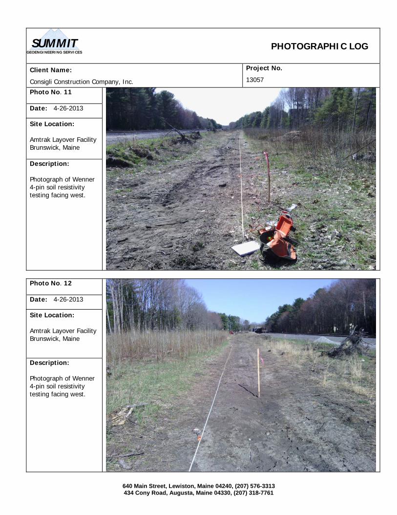
640 Main Street, Lewiston, Maine 04240, (207) 576-3313 434 Cony Road, Augusta, Maine 04330, (207) 318-7761
PHOTOGRAPHIC LOG
Client Name:
Consigli Construction Company, Inc.
Project No.
13057
Photo No. 11 Date: 4-26-2013 Site Location: Amtrak Layover Facility Brunswick, Maine Description: Photograph of Wenner 4-pin soil resistivity testing facing west.
Photo No. 12 Date: 4-26-2013 Site Location: Amtrak Layover Facility Brunswick, Maine Description: Photograph of Wenner 4-pin soil resistivity testing facing west.
GEOENGINEERING SERVICES
SUMMIT

APPENDIX C LABORATORY RESULTS
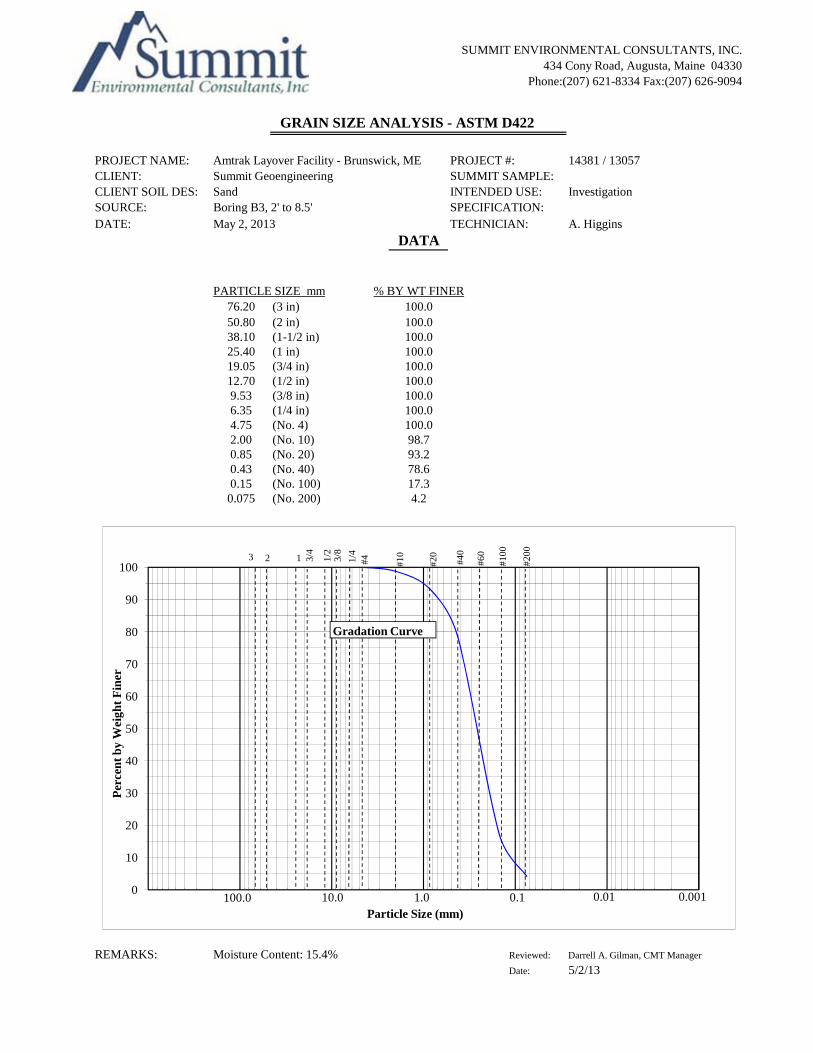
SUMMIT ENVIRONMENTAL CONSULTANTS, INC.434 Cony Road, Augusta, Maine 04330
Phone:(207) 621-8334 Fax:(207) 626-9094
GRAIN SIZE ANALYSIS - ASTM D422
PROJECT NAME: Amtrak Layover Facility - Brunswick, ME PROJECT #: 14381 / 13057CLIENT: Summit GeoengineeringCLIENT SOIL DES: Sand InvestigationSOURCE: Boring B3, 2' to 8.5'DATE: A. Higgins
DATA
PARTICLE SIZE mm % BY WT FINER76.20 (3 in) 100.050.80 (2 in) 100.0 38.10 (1-1/2 in) 100.025.40 (1 in) 100.019.05 (3/4 in) 100.012.70 (1/2 in) 100.09.53 (3/8 in) 100.06.35 (1/4 in) 100.04.75 (No. 4) 100.02.00 (No. 10) 98.70.85 (No. 20) 93.20.43 (No. 40) 78.60.15 (No. 100) 17.30.075 (No. 200) 4.2
SUMMIT SAMPLE:INTENDED USE:SPECIFICATION:TECHNICIAN:May 2, 2013
10023 1 3/
4
1/2
3/8
1/4
#4 #10
#20
#40
#60
#100
#200
REMARKS: Moisture Content: 15.4% Reviewed: Darrell A. Gilman, CMT Manager
Date: 5/2/13
0
10
20
30
40
50
60
70
80
90
Per
cen
t b
y W
eigh
t F
iner
Particle Size (mm)0.11.010.0100.0 0.0010.01
Gradation Curve

SUMMIT ENVIRONMENTAL CONSULTANTS, INC.434 Cony Road, Augusta, Maine 04330
Phone:(207) 621-8334 Fax:(207) 626-9094
GRAIN SIZE ANALYSIS - ASTM D422
PROJECT NAME: Amtrak Layover Facility - Brunswick, ME PROJECT #: 14381 / 13057CLIENT: Summit GeoengineeringCLIENT SOIL DES: Sand InvestigationSOURCE: Boring B3, 10' to 12'DATE: A. Higgins
DATA
PARTICLE SIZE mm % BY WT FINER76.20 (3 in) 100.050.80 (2 in) 100.0 38.10 (1-1/2 in) 100.025.40 (1 in) 100.019.05 (3/4 in) 100.012.70 (1/2 in) 100.09.53 (3/8 in) 99.76.35 (1/4 in) 99.64.75 (No. 4) 99.52.00 (No. 10) 97.70.85 (No. 20) 81.30.43 (No. 40) 49.00.15 (No. 100) 4.30.075 (No. 200) 0.6
SUMMIT SAMPLE:INTENDED USE:SPECIFICATION:TECHNICIAN:May 2, 2013
10023 1 3/
4
1/2
3/8
1/4
#4 #10
#20
#40
#60
#100
#200
REMARKS: Moisture Content: 23.8% Reviewed: Darrell A. Gilman, CMT Manager
Date: 5/2/13
0
10
20
30
40
50
60
70
80
90
Per
cen
t b
y W
eigh
t F
iner
Particle Size (mm)0.11.010.0100.0 0.0010.01
Gradation Curve

SUMMIT ENVIRONMENTAL CONSULTANTS, INC.434 Cony Road, Augusta, Maine 04330
Phone:(207) 621-8334 Fax:(207) 626-9094
GRAIN SIZE ANALYSIS - ASTM D422
PROJECT NAME: Amtrak Layover Facility - Brunswick, ME PROJECT #: 14381 / 13057CLIENT: Summit GeoengineeringCLIENT SOIL DES: Sand InvestigationSOURCE: Boring B3, 15' to 17'DATE: A. Higgins
DATA
PARTICLE SIZE mm % BY WT FINER76.20 (3 in) 100.050.80 (2 in) 100.0 38.10 (1-1/2 in) 100.025.40 (1 in) 100.019.05 (3/4 in) 100.012.70 (1/2 in) 100.09.53 (3/8 in) 100.06.35 (1/4 in) 100.04.75 (No. 4) 100.02.00 (No. 10) 100.00.85 (No. 20) 99.70.43 (No. 40) 99.60.15 (No. 100) 40.60.075 (No. 200) 4.8
SUMMIT SAMPLE:INTENDED USE:SPECIFICATION:TECHNICIAN:May 2, 2013
10023 1 3/
4
1/2
3/8
1/4
#4 #10
#20
#40
#60
#100
#200
REMARKS: Moisture Content: 24.8% Reviewed: Darrell A. Gilman, CMT Manager
Date: 5/2/13
0
10
20
30
40
50
60
70
80
90
Per
cen
t b
y W
eigh
t F
iner
Particle Size (mm)0.11.010.0100.0 0.0010.01
Gradation Curve

SUMMIT ENVIRONMENTAL CONSULTANTS, INC.434 Cony Road, Augusta, Maine 04330
Phone:(207) 621-8334 Fax:(207) 626-9094
GRAIN SIZE ANALYSIS - ASTM D422
PROJECT NAME: Amtrak Layover Facility - Brunswick, ME PROJECT #: 14381 / 13057CLIENT: Summit GeoengineeringCLIENT SOIL DES: Sand InvestigationSOURCE: Boring B11, 5' to 7'DATE: A. Higgins
DATA
PARTICLE SIZE mm % BY WT FINER76.20 (3 in) 100.050.80 (2 in) 100.0 38.10 (1-1/2 in) 100.025.40 (1 in) 100.019.05 (3/4 in) 100.012.70 (1/2 in) 100.09.53 (3/8 in) 100.06.35 (1/4 in) 99.84.75 (No. 4) 99.52.00 (No. 10) 97.80.85 (No. 20) 87.70.43 (No. 40) 45.40.15 (No. 100) 12.60.075 (No. 200) 5.6
SUMMIT SAMPLE:INTENDED USE:SPECIFICATION:TECHNICIAN:May 2, 2013
10023 1 3/
4
1/2
3/8
1/4
#4 #10
#20
#40
#60
#100
#200
REMARKS: Moisture Content: 22.7% Reviewed: Darrell A. Gilman, CMT Manager
Date: 5/2/13
0
10
20
30
40
50
60
70
80
90
Per
cen
t b
y W
eigh
t F
iner
Particle Size (mm)0.11.010.0100.0 0.0010.01
Gradation Curve

SUMMIT ENVIRONMENTAL CONSULTANTS, INC.434 Cony Road, Augusta, Maine 04330
Phone:(207) 621-8334 Fax:(207) 626-9094
GRAIN SIZE ANALYSIS - ASTM D422
PROJECT NAME: Amtrak Layover Facility - Brunswick, ME PROJECT #: 14381 / 13057CLIENT: Summit GeoengineeringCLIENT SOIL DES: Sand InvestigationSOURCE: Boring B11, 10' to 12'DATE: A. Higgins
DATA
PARTICLE SIZE mm % BY WT FINER76.20 (3 in) 100.050.80 (2 in) 100.0 38.10 (1-1/2 in) 100.025.40 (1 in) 100.019.05 (3/4 in) 100.012.70 (1/2 in) 100.09.53 (3/8 in) 100.06.35 (1/4 in) 100.04.75 (No. 4) 100.02.00 (No. 10) 99.50.85 (No. 20) 91.10.43 (No. 40) 28.40.15 (No. 100) 1.40.075 (No. 200) 0.4
SUMMIT SAMPLE:INTENDED USE:SPECIFICATION:TECHNICIAN:May 2, 2013
10023 1 3/
4
1/2
3/8
1/4
#4 #10
#20
#40
#60
#100
#200
REMARKS: Moisture Content: 21.5% Reviewed: Darrell A. Gilman, CMT Manager
Date: 5/2/13
0
10
20
30
40
50
60
70
80
90
Per
cen
t b
y W
eigh
t F
iner
Particle Size (mm)0.11.010.0100.0 0.0010.01
Gradation Curve

SUMMIT ENVIRONMENTAL CONSULTANTS, INC.434 Cony Road, Augusta, Maine 04330
Phone:(207) 621-8334 Fax:(207) 626-9094
GRAIN SIZE ANALYSIS - ASTM D422
PROJECT NAME: Amtrak Layover Facility - Brunswick, ME PROJECT #: 14381 / 13057CLIENT: Summit GeoengineeringCLIENT SOIL DES: Sand InvestigationSOURCE: Boring B11, 15' to 17'DATE: A. Higgins
DATA
PARTICLE SIZE mm % BY WT FINER76.20 (3 in) 100.050.80 (2 in) 100.0 38.10 (1-1/2 in) 100.025.40 (1 in) 100.019.05 (3/4 in) 100.012.70 (1/2 in) 100.09.53 (3/8 in) 100.06.35 (1/4 in) 100.04.75 (No. 4) 100.02.00 (No. 10) 100.00.85 (No. 20) 100.00.43 (No. 40) 99.80.15 (No. 100) 61.40.075 (No. 200) 9.0
SUMMIT SAMPLE:INTENDED USE:SPECIFICATION:TECHNICIAN:May 2, 2013
10023 1 3/
4
1/2
3/8
1/4
#4 #10
#20
#40
#60
#100
#200
REMARKS: Moisture Content: 23.1% Reviewed: Darrell A. Gilman, CMT Manager
Date: 5/2/13
0
10
20
30
40
50
60
70
80
90
Per
cen
t b
y W
eigh
t F
iner
Particle Size (mm)0.11.010.0100.0 0.0010.01
Gradation Curve

SUMMIT ENVIRONMENTAL CONSULTANTS, INC.434 Cony Road, Augusta, Maine 04330
Phone:(207) 621-8334 Fax:(207) 626-9094
GRAIN SIZE ANALYSIS - ASTM D422
PROJECT NAME: Amtrak Layover Facility - Brunswick, ME PROJECT #: 14381 / 13057CLIENT: Summit GeoengineeringCLIENT SOIL DES: Silty Sand InvestigationSOURCE: Boring B11, 20' to 22'DATE: A. Higgins
DATA
PARTICLE SIZE mm % BY WT FINER76.20 (3 in) 100.050.80 (2 in) 100.0 38.10 (1-1/2 in) 100.025.40 (1 in) 100.019.05 (3/4 in) 100.012.70 (1/2 in) 100.09.53 (3/8 in) 100.06.35 (1/4 in) 100.04.75 (No. 4) 100.02.00 (No. 10) 100.00.85 (No. 20) 100.00.43 (No. 40) 100.00.15 (No. 100) 65.80.075 (No. 200) 13.7
SUMMIT SAMPLE:INTENDED USE:SPECIFICATION:TECHNICIAN:May 2, 2013
10023 1 3/
4
1/2
3/8
1/4
#4 #10
#20
#40
#60
#100
#200
REMARKS: Moisture Content: 25.6% Reviewed: Darrell A. Gilman, CMT Manager
Date: 5/2/13
0
10
20
30
40
50
60
70
80
90
Per
cen
t b
y W
eigh
t F
iner
Particle Size (mm)0.11.010.0100.0 0.0010.01
Gradation Curve

SUMMIT ENVIRONMENTAL CONSULTANTS, INC. 434 Cony Road, Augusta, Maine 04330
Phone: (207) 621-8334 Fax: (207) 626-9094
Method "A" (Multi-point)
PROJECT NAME: PROJECT #:CLIENT: SAMPLE #:PROCEDURE: DEPTH:INTENDED USE: DATE:SAMPLE SOURCE: TECHNICIAN:
DATA
Depth LL PL PI20' to 22' 24 17 7
Source
Summit GeoengineeringA
ClassificationSilty Clay (CL-ML)
ATTERBERG LIMIT TEST - ASTM D4318
20' to 22'5/2/13N. Davis
Boring B16
InvestigationBoring B16
14381 / 13057Amtrak Layover Facility - Brunswick, ME
"U" Line
50
60
70
dex
"A" Line
Notes:
Reviewed: Darrell A. Gilman, CMT ManagerDate: 5/2/2013
0
10
20
30
40
0 10 20 30 40 50 60 70 80 90 100
Pla
stic
ity
Ind
Liquid Limit
CL or OL
CH or OH
MH or OH
ML or OLCL-ML
Moisture Content: 26.1%
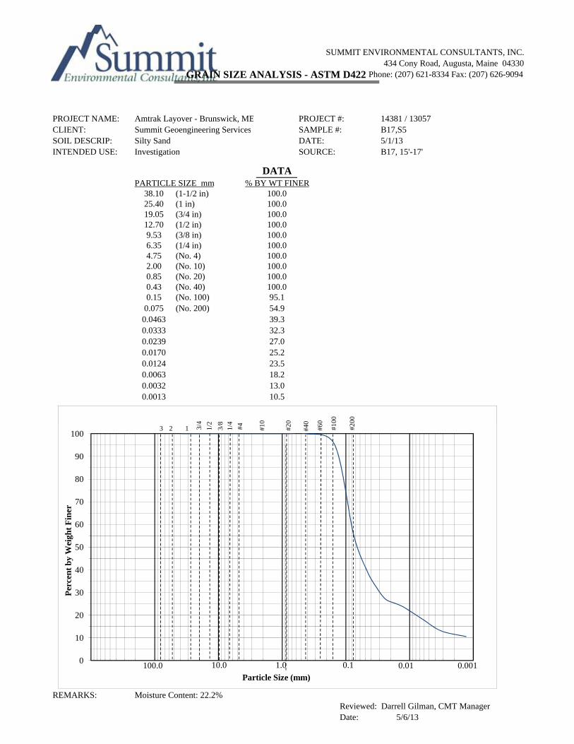
SUMMIT ENVIRONMENTAL CONSULTANTS, INC. 434 Cony Road, Augusta, Maine 04330
Phone: (207) 621-8334 Fax: (207) 626-9094
PROJECT NAME: Amtrak Layover - Brunswick, ME PROJECT #: 14381 / 13057CLIENT: Summit Geoengineering Services SAMPLE #: B17,S5SOIL DESCRIP: Silty Sand DATE: 5/1/13INTENDED USE: Investigation SOURCE: B17, 15'-17'
DATAPARTICLE SIZE mm % BY WT FINER
38.10 (1-1/2 in) 100.025.40 (1 in) 100.019.05 (3/4 in) 100.012.70 (1/2 in) 100.09.53 (3/8 in) 100.06.35 (1/4 in) 100.04.75 (No. 4) 100.02.00 (No. 10) 100.00.85 (No. 20) 100.00.43 (No. 40) 100.00.15 (No. 100) 95.1
0.075 (No. 200) 54.90.0463 39.30.0333 32.30.0239 27.00.0170 25.20.0124 23.50.0063 18.20.0032 13.00.0013 10.5
GRAIN SIZE ANALYSIS - ASTM D422
4 2 8 4 4 0 0 0 0 00 200
REMARKS: Moisture Content: 22.2%Reviewed: Darrell Gilman, CMT ManagerDate: 5/6/13
0
10
20
30
40
50
60
70
80
90
100
Per
cen
t b
y W
eigh
t F
iner
Particle Size (mm)
0.11.010.0100.0 0.0010.01
23 1 3/4
1/2
3/8
1/4
#4 #10
#20
#40
#60
#100
#200

SUMMIT ENVIRONMENTAL CONSULTANTS, INC. 434 Cony Road, Augusta, Maine 04330
Phone: (207) 621-8334 Fax: (207) 626-9094
PROJECT NAME: Amtrak Layover PROJECT #: 14381 / 13057CLIENT: Summit Geoengineering Services SAMPLE #: S5SOIL DESCRIP: Silty Sand DATE: 5/1/13INTENDED USE: Investigation SOURCE: B18, 15'-17'
DATAPARTICLE SIZE mm % BY WT FINER
38.10 (1-1/2 in) 100.025.40 (1 in) 100.019.05 (3/4 in) 100.012.70 (1/2 in) 100.09.53 (3/8 in) 100.06.35 (1/4 in) 100.04.75 (No. 4) 100.02.00 (No. 10) 100.00.85 (No. 20) 100.00.43 (No. 40) 100.00.15 (No. 100) 98.90.08 (No. 200) 69.0
0.0611 60.60.0449 48.30.0325 39.60.0167 30.80.0123 27.30.0063 18.20.0023 16.50.0013 14.0
GRAIN SIZE ANALYSIS - ASTM D422
4 2 8 4 4 0 0 0 0 00 200
REMARKS: Moisture Content: 23.7%Reviewed: Darrell Gilman, CMT ManagerDate: 5/6/13
0
10
20
30
40
50
60
70
80
90
100
Per
cen
t b
y W
eigh
t F
iner
Particle Size (mm)
0.11.010.0100.0 0.0010.01
23 1 3/4
1/2
3/8
1/4
#4 #10
#20
#40
#60
#100
#200

SUMMIT ENVIRONMENTAL CONSULTANTS, INC. 434 Cony Road, Augusta, Maine 04330
Phone: (207) 621-8334 Fax: (207) 626-9094
PROJECT NAME: Amtrak Layover - Brunswick, ME PROJECT #: 14381 / 13057CLIENT: Summit Geoengineering Services SAMPLE #: B18, S6SOIL DESCRIP: Silty Clay DATE: 5/1/13INTENDED USE: Investigation SOURCE: B18, 20'-22'
DATAPARTICLE SIZE mm % BY WT FINER
38.10 (1-1/2 in) 100.025.40 (1 in) 100.019.05 (3/4 in) 100.012.70 (1/2 in) 100.09.53 (3/8 in) 100.06.35 (1/4 in) 100.04.75 (No. 4) 100.02.00 (No. 10) 100.00.85 (No. 20) 100.00.43 (No. 40) 100.00.15 (No. 100) 93.8
0.075 (No. 200) 64.00.0611 56.20.0453 41.60.0330 31.80.0169 23.70.0088 18.80.0032 13.60.0013 11.4
GRAIN SIZE ANALYSIS - ASTM D422
4 2 8 4 4 0 0 0 0 00 200
REMARKS: Moisture Content 22.7%Reviewed: Darrell Gilman, CMT ManagerDate: 5/6/13
0
10
20
30
40
50
60
70
80
90
100
Per
cen
t b
y W
eigh
t F
iner
Particle Size (mm)
0.11.010.0100.0 0.0010.01
23 1 3/4
1/2
3/8
1/4
#4 #10
#20
#40
#60
#100
#200

SUMMIT ENVIRONMENTAL CONSULTANTS, INC.434 Cony Road, Augusta, Maine 04330
Phone:(207) 621-8334 Fax:(207) 626-9094
GRAIN SIZE ANALYSIS - ASTM D422
PROJECT NAME: Amtrak Layover Facility - Brunswick, ME PROJECT #: 14381 / 13057CLIENT: Summit GeoengineeringCLIENT SOIL DES: Sand InvestigationSOURCE: Boring B26, 2' to 7'DATE: A. Higgins
DATA
PARTICLE SIZE mm % BY WT FINER76.20 (3 in) 100.050.80 (2 in) 100.0 38.10 (1-1/2 in) 100.025.40 (1 in) 100.019.05 (3/4 in) 100.012.70 (1/2 in) 100.09.53 (3/8 in) 99.06.35 (1/4 in) 98.84.75 (No. 4) 98.52.00 (No. 10) 96.40.85 (No. 20) 87.80.43 (No. 40) 52.00.15 (No. 100) 4.00.075 (No. 200) 1.6
SUMMIT SAMPLE:INTENDED USE:SPECIFICATION:TECHNICIAN:May 2, 2013
10023 1 3/
4
1/2
3/8
1/4
#4 #10
#20
#40
#60
#100
#200
REMARKS: Moisture Content: 6.9% Reviewed: Darrell A. Gilman, CMT Manager
Date: 5/2/13
0
10
20
30
40
50
60
70
80
90
Per
cen
t b
y W
eigh
t F
iner
Particle Size (mm)0.11.010.0100.0 0.0010.01
Gradation Curve
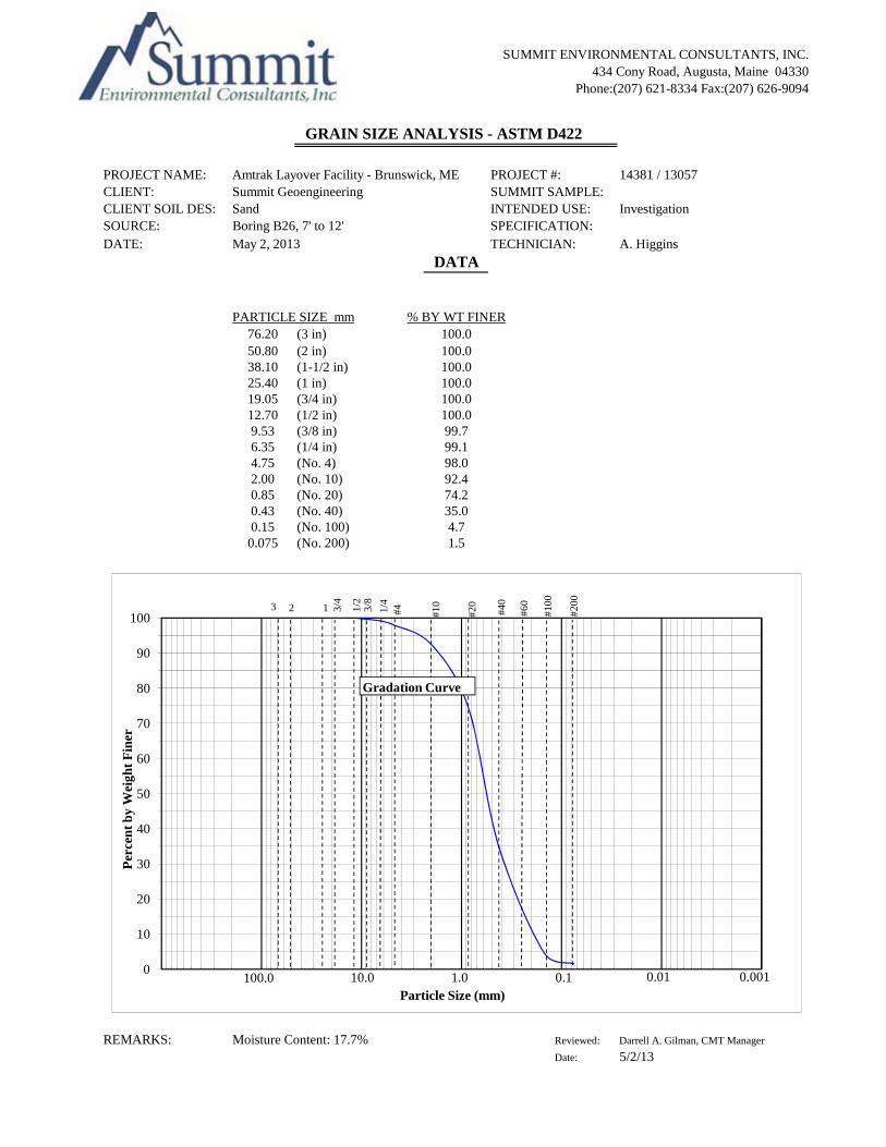
SUMMIT ENVIRONMENTAL CONSULTANTS, INC.434 Cony Road, Augusta, Maine 04330
Phone:(207) 621-8334 Fax:(207) 626-9094
GRAIN SIZE ANALYSIS - ASTM D422
PROJECT NAME: Amtrak Layover Facility - Brunswick, ME PROJECT #: 14381 / 13057CLIENT: Summit GeoengineeringCLIENT SOIL DES: Sand InvestigationSOURCE: Boring B26, 7' to 12'DATE: A. Higgins
DATA
PARTICLE SIZE mm % BY WT FINER76.20 (3 in) 100.050.80 (2 in) 100.0 38.10 (1-1/2 in) 100.025.40 (1 in) 100.019.05 (3/4 in) 100.012.70 (1/2 in) 100.09.53 (3/8 in) 99.76.35 (1/4 in) 99.14.75 (No. 4) 98.02.00 (No. 10) 92.40.85 (No. 20) 74.20.43 (No. 40) 35.00.15 (No. 100) 4.70.075 (No. 200) 1.5
SUMMIT SAMPLE:INTENDED USE:SPECIFICATION:TECHNICIAN:May 2, 2013
10023 1 3/
4
1/2
3/8
1/4
#4 #10
#20
#40
#60
#100
#200
REMARKS: Moisture Content: 17.7% Reviewed: Darrell A. Gilman, CMT Manager
Date: 5/2/13
0
10
20
30
40
50
60
70
80
90
Per
cen
t b
y W
eigh
t F
iner
Particle Size (mm)0.11.010.0100.0 0.0010.01
Gradation Curve

SUMMIT ENVIRONMENTAL CONSULTANTS, INC. 434 Cony Road, Augusta, Maine 04330
Phone: (207) 621-8334 Fax: (207) 626-9094
PROJECT NAME: Amtrak Layover - Brunswick, ME PROJECT #: 14381 / 13057CLIENT: Summit Geoengineering Services SAMPLE #: B26,S6SOIL DESCRIP: Clayey Silt DATE: 5/1/13INTENDED USE: Investigation SOURCE: B26, 15'-17'
DATAPARTICLE SIZE mm % BY WT FINER
38.10 (1-1/2 in) 100.025.40 (1 in) 100.019.05 (3/4 in) 100.012.70 (1/2 in) 100.09.53 (3/8 in) 100.06.35 (1/4 in) 100.04.75 (No. 4) 100.02.00 (No. 10) 100.00.85 (No. 20) 100.00.43 (No. 40) 100.00.15 (No. 100) 99.6
0.075 (No. 200) 91.00.0579 73.10.0437 54.70.0329 34.60.0168 26.20.0089 19.10.0045 15.80.0023 14.10.0013 10.1
GRAIN SIZE ANALYSIS - ASTM D422
4 2 8 4 4 0 0 0 0 00 200
REMARKS: Moisture Content: 26.5 %Reviewed: Darrell Gilman, CMT ManagerDate: 5/6/13
0
10
20
30
40
50
60
70
80
90
100
Per
cen
t b
y W
eigh
t F
iner
Particle Size (mm)
0.11.010.0100.0 0.0010.01
23 1 3/4
1/2
3/8
1/4
#4 #10
#20
#40
#60
#100
#200


![13057-DANIEL LE GOURRIEREC-En Quete de Correspondance-[InLibroVeritas.net]](https://img.pdfslide.net/doc/110x75/55cf99b9550346d0339edb14/13057-daniel-le-gourrierec-en-quete-de-correspondance-inlibroveritasnet.jpg)