Embed Size (px)
Citation preview
137-18 Appendix A - Technical Specifications
B52 and B53 Transition Duct Liner System Replacement

Page 2 of 10
TABLE OF CONTENTS
1.0 LOCATION OF PROPERTY ........................................................................................... 3
2.0 SCOPE OF WORK............................................................................................................. 3
3.0 CODES AND STANDARDS .............................................................................................. 3
4.0 EXISTING TRANSITION DUCT DESCRIPTION ....................................................... 4
5.0 DEMOLITION AND REMOVAL .................................................................................... 5
6.0 HAZARDOUS MATERIAL REMOVAL ........................................................................ 5
7.0 REPLACEMENT TRANSITION DUCT LINER AND INSULATION ....................... 6
8.0 MATERIAL AND FABRICATION ................................................................................. 6
9.0 WELDING AND FABRICATION TOLERANCES ....................................................... 7
10.0 PROTECTIVE COATINGS .............................................................................................. 7
11.0 SHIPMENT ......................................................................................................................... 8
12.0 DOCUMENTATION .......................................................................................................... 8
13.0 REFERENCE DRAWINGS AND MANUALS................................................................ 8
14.0 CONSTRUCTION .............................................................................................................. 9

Page 3 of 10
1.0 Location of Property
JEA Brandy Branch Generating Station is located at 15701 West Beaver Street,
Jacksonville, Florida 32234.
2.0 Scope of Work
2.1. This specification covers the engineering, design, fabrication, and installation of inlet liner
system (including insulation) in the first three (3) sections of the transition duct and the
turbine exhaust diffuser duct liners for two gas turbine unit as described herein. This
specification also covers demolition and removal of the entire existing liner sections of the
first three transition duct sections and diffuser duct liners on each gas turbine. The awarded
Company is to furnish all labor, supervision, material, cranes, subcontracts, etc. to engineer,
design, fabricate, deliver to the site, unload, and install new replacement liner, hardware,
and insulation system for the first three sections of each Heat Recovery Steam Generator
(HRSG) transition duct in its entirety (4 surfaces).
2.1.1. The Company shall remove and dispose of the existing transition duct liner and
insulation system in the sections that are being replaced. The Company shall provide
all material and labor for installation of the new liner and insulation in the specified
transition ducts sections. The interior liner surfaces shall be 10 GA 304SS panels
with pre‐cut stud holes.
2.1.2. The Company shall remove and dispose of the existing turbine exhaust diffuser duct
liner and insulation and replace with an upgraded system. The Company shall
provide all material and labor for installation of the new turbine exhaust diffuser
duct liner. The diffuser duct liner shall be 10 GA 304SS panels, pre-cut and roller to
match the existing round/tapering duct design.
2.1.3. The Company shall take every precaution to not damage the existing structural steel
support system. It is intended that this support system will be reused and that the
new transition duct liner sections will fit and connect to the existing structure as they
now exist.
2.1.4. The Company shall remove the liner and insulation in the transition ductwork
starting at the square to round expansion joint. The Company will be allowed to
make a temporary window to remove material from the interior of the transition
duct, but shall be responsible for restoring the transition duct upon completion of all
interior work. Also, the Company shall replace the first door in each transition duct
section with a door that is 48 inches minimum diagonally. The Company shall
replace, with new, the 12” Fabric joint and insulation pillow between the turbine
exhaust and transition ductwork. EJCON Corp. fabricated the existing 12” fabric
expansion joint. Refer to Paragraph 8.5 for expansion joint specification.
3.0 Codes and Standards

Page 4 of 10
The following codes and standards, as amended to date, are applicable under this contract:
Codes, Rules and Regulations of the State of Florida
Occupational Safety and Health (OSHA)
29 CFR Parts 1926.1101, 1926.62 and 1926.850 through1926.859
American Society for Testing and Materials (ASTM)
A-36 Structural Steel
A-240 Stainless and Heat-Resisting Chromium Steel Plates, Sheet and Strip
A-285 Pressure Vessel Plates, Carbon Steel, Low and Intermediate Tensile Strength
A-325 High-Strength Bolts for Structural Steel Joints
Steel Structures Painting Council (SSPC) Surface Preparation as Specified
American Welding Society (AWS) Structural Welding Code, Steel (AWS D1.1)
American Welding Society (AWS) Structural Welding Code
Sheet Metal (AWS D1.3)
American Institute of Steel Construction (AISC)
Manual of Steel Construction, 13th Edition
American Society of Civil Engineers (ASCE)
ASCE Standard ANSI/ASCE 7-2010
American National Standard
ANSI B133.8 “Gas Turbine Installation Sound Emissions”
4.0 Existing Transition Duct Description
4.1. The existing transition duct for Unit 2 and Unit 3 are located downstream of the turbine
exhaust, between the gas turbine and HRSG. There has been deterioration to the internal
liner and insulation due to thermal stresses and corrosion from exhaust emissions.
4.2. The existing turbine exhaust diffuser duct liner for Unit 2 and 3 are standard GE 7FA.
There has been some cracking and signs of breakdown in the diffuser duct liner due to
thermal stresses.
4.3. The general dimensions of the transition duct and diffuser duct liner are shown on the
reference drawings by Nooter/Eriksen. The diffuser liner can be seen on drawings provided,
Page 5 of 10
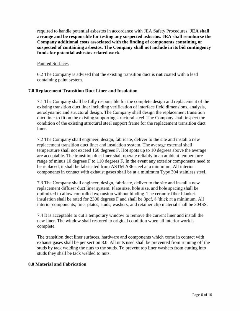
but dimensions will need to be verified. The replacement transition duct liner and insulation
system shall be designed and fabricated to match the overall dimensions of existing
components to insure a proper fit. It is also required that transition duct utilize the existing
structural steel support structure. The shell is constructed of ASTM – A36 steel. The shell
plate is generally a minimum of 3/8” inch thick steel. All interior liner materials, exposed to
hot gases, are 409 stainless steel. The insulation panels are approximately 8 inches thick.
4.4. The anticipated exhaust gas flow after .05 upgrade for the GE Frame 7FA gas turbine is
3994 kpph with an average exhaust temperature of 1189 degrees F while operating on
natural gas. The design internal temperature is 1250 degrees F.
5.0 Demolition and Removal
5.1 The transition duct liner and turbine exhaust diffuser duct liner replacement will be
done in conjunction with a gas turbine .05 upgrade as well as other plant projects. The
Company must use extreme caution as other Companies and equipment may enter and exit
the work area.
5.2 Extreme care must be taken so that no damage is done to the JEA’s station facilities
that will remain in operation during the demolition work. It is emphasized that facilities
located adjacent to and below grade in the working area are very essential elements of the
plant. All such adjacent facilities must be kept guaranteed safe during all demolition and
installation work. When possible, these facilities will be de-energized by JEA personnel.
JEA will provide a mark-out of these facilities.
5.3 The Company shall erect and properly maintain at all times such danger signs,
barricades, lights and other safeguards as may be required for safe working conditions.
5.4 All materials from the demolition become the property of the Company and shall be
removed promptly from the site. Removal of debris from the site shall be done frequently so
as to avoid any collection of debris.
5.5 The Company is advised that some of the material to be disposed of will contain various
insulation materials such as Birfelt, fiberglass, mineral wool, and fiberglass cloth.
6.0 Hazardous Material Removal
Potential Asbestos Removal
6.1 It is not expected that the Company will encounter any asbestos containing material in
the demolition of the existing silencer systems. There are no gaskets between the gas turbine
exhaust and transition duct sections. The gaskets on the man way hatches are fiberglass. If
the Company suspects that any components of the transition duct contain asbestos, the
Company shall notify the JEA Project Manager. The Company is advised that any material
suspected of containing asbestos will have to be treated as asbestos containing material until
cleared by testing. The Company shall observe all safety standards and procedures as
Page 6 of 10
required to handle potential asbestos in accordance with JEA Safety Procedures. JEA shall
arrange and be responsible for testing any suspected asbestos. JEA shall reimburse the
Company additional costs associated with the finding of components containing or
suspected of containing asbestos. The Company shall not include in its bid contingency
funds for potential asbestos related work.
Painted Surfaces
6.2 The Company is advised that the existing transition duct is not coated with a lead
containing paint system.
7.0 Replacement Transition Duct Liner and Insulation
7.1 The Company shall be fully responsible for the complete design and replacement of the
existing transition duct liner including verification of interface field dimensions, analysis,
aerodynamic and structural design. The Company shall design the replacement transition
duct liner to fit on the existing supporting structural steel. The Company shall inspect the
condition of the existing structural steel support frame for the replacement transition duct
liner.
7.2 The Company shall engineer, design, fabricate, deliver to the site and install a new
replacement transition duct liner and insulation system. The average external shell
temperature shall not exceed 160 degrees F. Hot spots up to 10 degrees above the average
are acceptable. The transition duct liner shall operate reliably in an ambient temperature
range of minus 10 degrees F to 110 degrees F. In the event any exterior components need to
be replaced, it shall be fabricated from ASTM A36 steel at a minimum. All interior
components in contact with exhaust gases shall be at a minimum Type 304 stainless steel.
7.3 The Company shall engineer, design, fabricate, deliver to the site and install a new
replacement diffuser duct liner system. Plate size, hole size, and hole spacing shall be
optimized to allow controlled expansion without binding. The ceramic fiber blanket
insulation shall be rated for 2300 degrees F and shall be 8pcf, 8”thick at a minimum. All
interior components; liner plates, studs, washers, and retainer clip material shall be 304SS.
7.4 It is acceptable to cut a temporary window to remove the current liner and install the
new liner. The window shall restored to original condition when all interior work is
complete.
The transition duct liner surfaces, hardware and components which come in contact with
exhaust gases shall be per section 8.0. All nuts used shall be prevented from running off the
studs by tack welding the nuts to the studs. To prevent top liner washers from cutting into
studs they shall be tack welded to nuts.
8.0 Material and Fabrication

Page 7 of 10
8.1 The Company is responsible for the design and fabrication of the transition duct liner.
Structural components of the design shall be in accordance with the applicable AISC,
ASTM and related codes.
8.2 The following minimum material requirements shall be adhered to in the design and
fabrication of exhaust transition duct liner and diffuser duct liner:
A. Exhaust transition duct shell plate shall be ASTM A36, 3/8” thickness.
B. Internal Liner shall be Type 304 stainless steel sheets, minimum 10 gage.
8.3 Interior hardware shall be machined studs ¾” dia. 304SS with 304SS nuts. Top and
bottom liner washers, pin point and guide washers, and liner corner angles shall all be 10
GA 304SS. The transition piece retaining clips shall be 304SS.
8.4 Insulation shall be 8” thick 8pcf ceramic fiber blanket rated at 2300 degrees F.
Insulation can be compressed one inch to 7” thick during installation.
8.5 The minimum material requirements for the turbine exhaust to transition duct expansion
joint are detailed on drawing M010322-201A003 and 007. The joint was fabricated by
EJCON and their information is shown below:
The existing Expansion joint was fabricated by EJCON Corp. 5502 Shawland Rd.
Jacksonville, FL 32236. Mike Crawford is Representative. 904-786-0622
[email protected]. It is the Company’s option to utilize EJCON or supply an approved
equal expansion joint.
9.0 Welding and Fabrication Tolerances
9.1 Fabrication tolerances shall be in accordance with industrial standards and shall be in
accordance with the Company’s design drawings.
9.2 Quality and appearance of welding is extremely important and shall be in accordance
with the practices and procedures of the AWS D1.1, Structural Welding Code, steel, and
AWS D1.3, Structural Welding Code, Sheet Metal.
All surfaces to be welded shall be suitably prepared and free of all foreign materials
detrimental to welding such as grease, oil, dirt and paint.
Proper welding electrodes shall be selected from AWS keeping in mind the base metal to be
welded and the welding process to be used.
9.3 Only certified welders shall perform the welding.
10.0 Protective Coatings
Page 8 of 10
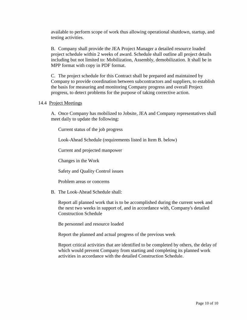
10.1 Damaged areas of external coating shall be repaired in accordance with coatings
specifications in attachment documents. Use COATING SYSTEM DATA SHEET
SYSTEM A1.
11.0 Shipment
11.1 The Company shall be fully responsible for the safe shipment, storage and handling of
the components of the transition duct liner. The Company shall be fully responsible for the
transition duct liner on the job site until the system is turned over to the Plant. The Company
is responsible for all shipping costs and for all truck loading and unloading of material at the
job site.
11.2 Hardware, and other miscellaneous parts shall be packed in suitable boxes for storage
at the job site.
12.0 Documentation
12.1 Shop Drawings
12.1.1 The Company shall submit to JEA for approval the proposed liner and
insulation system layout and design.
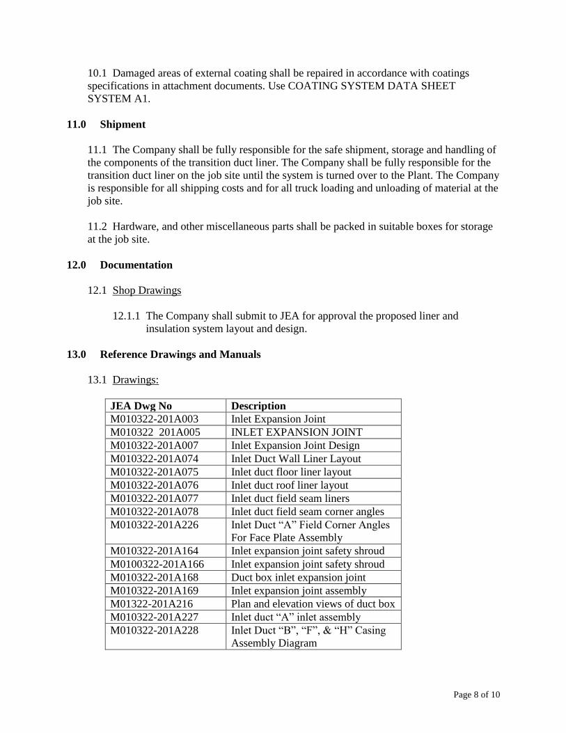
13.0 Reference Drawings and Manuals
13.1 Drawings:
JEA Dwg No Description
M010322-201A003 Inlet Expansion Joint
M010322 201A005 INLET EXPANSION JOINT
M010322-201A007 Inlet Expansion Joint Design
M010322-201A074 Inlet Duct Wall Liner Layout
M010322-201A075 Inlet duct floor liner layout
M010322-201A076 Inlet duct roof liner layout
M010322-201A077 Inlet duct field seam liners
M010322-201A078 Inlet duct field seam corner angles
M010322-201A226 Inlet Duct “A” Field Corner Angles
For Face Plate Assembly
M010322-201A164 Inlet expansion joint safety shroud
M0100322-201A166 Inlet expansion joint safety shroud
M010322-201A168 Duct box inlet expansion joint
M010322-201A169 Inlet expansion joint assembly
M01322-201A216 Plan and elevation views of duct box
M010322-201A227 Inlet duct “A” inlet assembly
M010322-201A228 Inlet Duct “B”, “F”, & “H” Casing
Assembly Diagram
Page 9 of 10
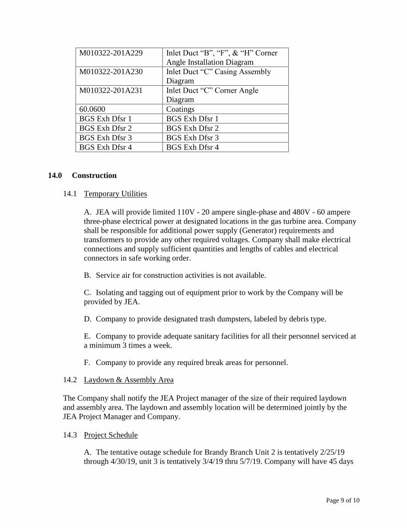
6900AX Sheet 1 of M010322-201A229 Inlet Duct “B”, “F”, & “H” Corner
Angle Installation Diagram
M010322-201A230 Inlet Duct “C” Casing Assembly
Diagram
M010322-201A231 Inlet Duct “C” Corner Angle
Diagram
60.0600 Coatings
BGS Exh Dfsr 1 BGS Exh Dfsr 1
BGS Exh Dfsr 2 BGS Exh Dfsr 2
BGS Exh Dfsr 3 BGS Exh Dfsr 3
BGS Exh Dfsr 4 BGS Exh Dfsr 4
14.0 Construction
14.1 Temporary Utilities
A. JEA will provide limited 110V - 20 ampere single-phase and 480V - 60 ampere
three-phase electrical power at designated locations in the gas turbine area. Company
shall be responsible for additional power supply (Generator) requirements and
transformers to provide any other required voltages. Company shall make electrical
connections and supply sufficient quantities and lengths of cables and electrical
connectors in safe working order.
B. Service air for construction activities is not available.
C. Isolating and tagging out of equipment prior to work by the Company will be
provided by JEA.
D. Company to provide designated trash dumpsters, labeled by debris type.
E. Company to provide adequate sanitary facilities for all their personnel serviced at
a minimum 3 times a week.
F. Company to provide any required break areas for personnel.
14.2 Laydown & Assembly Area
The Company shall notify the JEA Project manager of the size of their required laydown
and assembly area. The laydown and assembly location will be determined jointly by the
JEA Project Manager and Company.
14.3 Project Schedule
A. The tentative outage schedule for Brandy Branch Unit 2 is tentatively 2/25/19
through 4/30/19, unit 3 is tentatively 3/4/19 thru 5/7/19. Company will have 45 days
Page 10 of 10
available to perform scope of work thus allowing operational shutdown, startup, and
testing activities.
B. Company shall provide the JEA Project Manager a detailed resource loaded
project schedule within 2 weeks of award. Schedule shall outline all project details
including but not limited to: Mobilization, Assembly, demobilization. It shall be in
MPP format with copy in PDF format.
C. The project schedule for this Contract shall be prepared and maintained by
Company to provide coordination between subcontractors and suppliers, to establish
the basis for measuring and monitoring Company progress and overall Project
progress, to detect problems for the purpose of taking corrective action.
14.4 Project Meetings
A. Once Company has mobilized to Jobsite, JEA and Company representatives shall
meet daily to update the following:
Current status of the job progress
Look-Ahead Schedule (requirements listed in Item B. below)
Current and projected manpower
Changes in the Work
Safety and Quality Control issues
Problem areas or concerns
B. The Look-Ahead Schedule shall:
Report all planned work that is to be accomplished during the current week and
the next two weeks in support of, and in accordance with, Company's detailed
Construction Schedule
Be personnel and resource loaded
Report the planned and actual progress of the previous week
Report critical activities that are identified to be completed by others, the delay of
which would prevent Company from starting and completing its planned work
activities in accordance with the detailed Construction Schedule.
-1
Section 60.0600 - COATINGS 1.0 PAINTING. 1.1 General. This section covers the requirements for shop and field application of protective coatings and painting. Each painting system shall provide an optimum life expectancy of 10 years from the time of original painting. The environment shall be considered a Severe Environment - Heavy Industrial and Chemical Plant area with high levels of fumes and fallout as defined by SSPC. Coatings are also subjected to seawater attack common for a coastal envi-ronment. The optimum life of a coating system will be considered the time until first maintenance painting/touchup should occur, when 3 percent to 5 percent breakdown of the topcoats occurs, before active rusting begins. Surfaces which will be inaccessible after assembly shall be protected for the life of the equipment. Painting work shall include the protection of surfaces not to be painted and surface preparation, furnishing and applying paint materials, and other work incidental to painting which is required to properly execute the painting work. All external metallic surfaces of equipment provided under these specifications which is subject to corrosion shall be cleaned and prepared in accordance with the Coating System Data Sheets included at the end of this section, and shall be protected by the specified coatings. Surfaces which will be inaccessible after assembly shall be protected for the life of the equipment. Piping shall be painted in accordance with JEA's color scheme. 1.2 Scope of Painting. Except for those surfaces excluded hereinafter, all exposed surfaces of all facilities constructed or otherwise incorporated into the scope of work shall be painted. Exposed surfaces shall mean all interior and exterior surfaces which are not encased or covered by the finished building structure or equipment and which are visible and accessible for painting. In addition, surfaces of equipment and piping to be insulated shall be prime painted with one coat of primer per Coating System Data Sheet E45. Areas which would be difficult or impossible to paint after all construction is complete shall be painted at a stage during construction when painting is possible. Abraded or damaged areas of shop primed surfaces shall be cleaned and touchup painted before applying finish paint system. Abraded or damaged areas of shop finish painted surfaces shall be repaired by spot priming and repainting. Motors and accessories for equipment shall be painted with the same paint system and color specified for the equipment. Exposed surfaces of electrical conduit, conduit boxes, and fittings shall be painted only where they are adjacent to painted parts of the building structure or equipment. These surfaces shall be painted the same color as the adjacent building surfaces. 1.2.1 Surfaces to be Painted. Exposed surfaces of the interior and exterior of all building structures and components and the exposed surfaces of all equipment, piping, valves, and hangers, unless excluded hereinafter shall be finish painted. Stainless steel piping and other stainless steel surfaces to be insulated, or exposed to a chloride bearing atmosphere shall be painted in accordance with the paint manufacturers’ recommendations.
-2
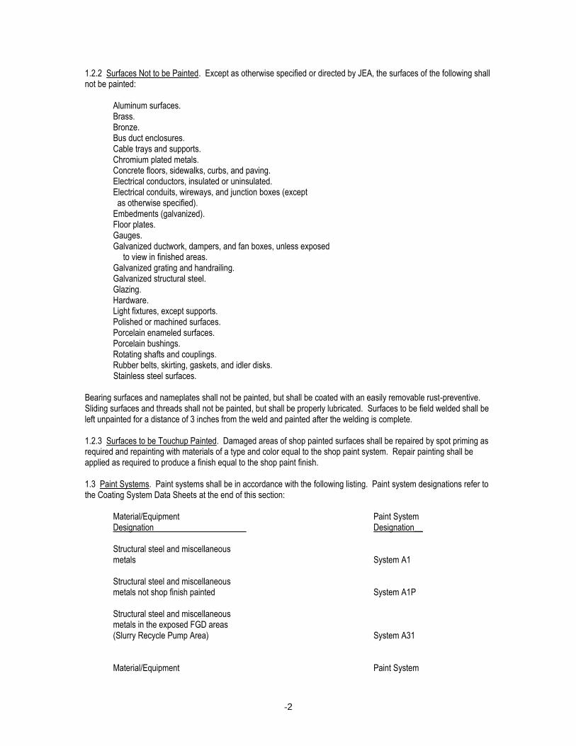
1.2.2 Surfaces Not to be Painted. Except as otherwise specified or directed by JEA, the surfaces of the following shall not be painted:
Aluminum surfaces. Brass. Bronze. Bus duct enclosures. Cable trays and supports. Chromium plated metals. Concrete floors, sidewalks, curbs, and paving. Electrical conductors, insulated or uninsulated. Electrical conduits, wireways, and junction boxes (except as otherwise specified). Embedments (galvanized). Floor plates. Gauges. Galvanized ductwork, dampers, and fan boxes, unless exposed
to view in finished areas. Galvanized grating and handrailing. Galvanized structural steel. Glazing. Hardware. Light fixtures, except supports. Polished or machined surfaces. Porcelain enameled surfaces. Porcelain bushings. Rotating shafts and couplings. Rubber belts, skirting, gaskets, and idler disks. Stainless steel surfaces.
Bearing surfaces and nameplates shall not be painted, but shall be coated with an easily removable rust-preventive. Sliding surfaces and threads shall not be painted, but shall be properly lubricated. Surfaces to be field welded shall be left unpainted for a distance of 3 inches from the weld and painted after the welding is complete. 1.2.3 Surfaces to be Touchup Painted. Damaged areas of shop painted surfaces shall be repaired by spot priming as required and repainting with materials of a type and color equal to the shop paint system. Repair painting shall be applied as required to produce a finish equal to the shop paint finish. 1.3 Paint Systems. Paint systems shall be in accordance with the following listing. Paint system designations refer to the Coating System Data Sheets at the end of this section:
Material/Equipment Paint System Designation Designation__ Structural steel and miscellaneous
metals System A1 Structural steel and miscellaneous metals not shop finish painted System A1P Structural steel and miscellaneous metals in the exposed FGD areas (Slurry Recycle Pump Area) System A31
Material/Equipment Paint System
-3
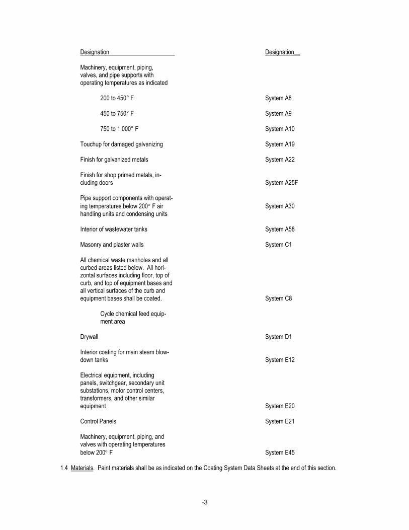
Designation Designation__ Machinery, equipment, piping,
valves, and pipe supports with operating temperatures as indicated
200 to 450° F System A8
450 to 750° F System A9
750 to 1,000° F System A10 Touchup for damaged galvanizing System A19
Finish for galvanized metals System A22
Finish for shop primed metals, in-
cluding doors System A25F
Pipe support components with operat-
ing temperatures below 200 F air System A30 handling units and condensing units Interior of wastewater tanks System A58
Masonry and plaster walls System C1 All chemical waste manholes and all
curbed areas listed below. All hori- zontal surfaces including floor, top of curb, and top of equipment bases and all vertical surfaces of the curb and equipment bases shall be coated. System C8
Cycle chemical feed equip- ment area
Drywall System D1
Interior coating for main steam blow-
down tanks System E12 Electrical equipment, including
panels, switchgear, secondary unit substations, motor control centers,
transformers, and other similar equipment System E20
Control Panels System E21
Machinery, equipment, piping, and valves with operating temperatures
below 200 F System E45 1.4 Materials. Paint materials shall be as indicated on the Coating System Data Sheets at the end of this section.

-4
Paint materials shall be stored in sealed, original labelled containers bearing manufacturer's name, type of paint, brand name, color designation, and instructions for mixing and/or reducing. The manufacturer's recommended application instructions for each type of paint shall be included with each shipment of paint. Except for catalyzed coatings, all paint shall be factory mixed in correct proportions and consistency suitable for direct application in warm weather without addition of thinners. Pigments shall be fully ground maintaining a soft paste consistency, capable of being readily and uniformly dispersed to a complete homogeneous mixture. Materials from the same manufacturer shall be applied for all coats in each coating system. 1.4.1 Manufacturers. Except as otherwise acceptable to JEA, coatings shall be formulated and compounded by manufacturers named in the Coating System Data Sheets at the end of this section. 1.4.2 Colors. Finish paint colors will be generally selected from the manufacturer's standard line of colors. Sample boards showing the proposed color scheme for each area shall be prepared and submitted to JEA for color selection. The sample boards shall include samples of each finish material labeled with the manufacturer and color name of each sample. A minimum of three final sample boards shall be submitted after final JEA selection. 1.4.3 Preservative Coatings. Ferrous surfaces which should not be painted and are subject to corrosion shall be protected with preservative coatings. All preservative coatings which are used to protect surfaces of equipment that are exposed to the feedwater or steam shall be completely water soluble. Other surfaces shall be coated with rust-preventive compound, equivalent to Houghton "Rust Veto 344" or Rust-Oleum "R-9." The manufacturer and manu-facturer's designation of all preservative coatings proposed to be used shall be submitted to JEA for acceptance prior to application. Machined surfaces of weld-end preparations and surfaces within 3 inches of field welds shall be coated with consuma-ble rust-preventive coating equivalent to "Deoxalumite" manufactured by Special Chemicals Corp. or "Bloxide" manufactured by Tempil Division of Big Three Industries. 1.4.4 Galvanizing. Galvanizing specified in the detailed specifications will be in accordance with the following requirements. Structural steel members and steel assemblies shall be "pickled" after all cutting, punching, reaming, drilling, tapping, and other fabrication processes which would damage galvanizing have been completed. The pickling shall be done in accordance with the latest accepted practice and shall continue until all scale, rust, grease, and other impurities have been completely removed. The steel shall then be hot-dip galvanized in accordance with ASTM A123. Where either member to be bolted is galvanized and where required by the detailed specifications, erection and structural bolts shall be galvanized in accordance with ASTM A153. 1.4.5 Manufacturer’s Recommended Practices. Storage, surface preparation, and application for coating materials shall be in accordance with the manufacturer’s recommendations. 2.0 UNDERGROUND PROTECTIVE COATINGS. The Contractor shall furnish and apply a protective coating to the exterior surface of all underground, buried steel piping. The exterior surface of buried steel piping shall be cleaned, coated, tested, and handled in accordance with AWWA C203 together with the applicable sections in the appendices of those specifications, or JEA approved equal. The applicable sections of those specifications have been incorporated herein. The interior of the pipe shall be cleaned, grit or sand blasted, and coated in the shop. 2.1 Coatings. The protective coating for the exterior surfaces of steel pipe shall consist of a coat of coal-tar primer, a 3/32 inch thick coating of hot coal-tar enamel, a fibrous glass mat, a 4 mil thick coating of hot coal-tar enamel, a bonded wrap of nonasbestos felt, and a coating of white wash. The exterior surface of pipe to be totally encased in concrete shall be coated with the coal-tar primer only. 2.2 Application. The protective coating shall be applied as specified below.

-5
2.2.1 General. The protective coatings shall be shop applied after fabrication and before erection except for the surfaces at the pipe ends. The coating shall be left off of pipe ends for a distance of approximately 6 inches to permit the welding of joints without injury to the coatings. After the sections of pipe are welded together, the areas left uncoated and all damaged areas shall be cleaned and coated. 2.2.2 Workmanship. All work shall be done in a thorough workmanlike manner. The entire operation of priming the pipe and heating and applying the coal-tar epoxy and enamel coatings shall be performed under the supervision of and by experienced personnel skilled in the application of coal-tar enamel and coal-tar epoxy coating systems. 2.2.3 Equipment. The Contractor's equipment for all blasting, priming, enameling, and painting shall be designed and manufactured for the specific application and shall be in such condition as to permit applicators to follow the procedure and obtain results prescribed in these specifications. 2.2.4 Preparation of Surfaces. All surfaces of piping shall be thoroughly cleaned in accordance with Steel Structures Painting Council (SSPC) Surface Preparation Specification No.1, Solvent Cleaning to remove all oil, grease, moisture, dirt, rust, mill scale, weld scale, and other foreign materials prior to the application of any coating. This shall be accomplished by the use of suitable solvents to remove oil and grease, followed by sandblasting. The solvent shall be Xylol or some other suitable coal-tar base solvent. Dirty solvent shall not be used. Dirty and/or oily rags shall also not be used. The Contractor shall place all used solvent and rags in a suitable container and remove them from the site for disposal in an environmentally safe manner. Exterior surfaces shall be dry grit blasted in accordance with Steel Structures Painting Council (SSPC) Surface Preparation Specification No. 10, Near-White Blast Cleaning. Interior surfaces shall be dry grit blasted in accordance with SSPC-SP5, White Metal Blast-Cleaning. Grit and dust shall be removed thoroughly by blowing before primer is applied. All other foreign matter not removable by blasting shall be removed by suitable means. Blasted surfaces that rust before a priming coat has been applied shall be cleaned of all rust by buffing or wire brushing or, at the discretion of JEA, shall be reblasted. Adequate air separators shall be used to remove all oil and free moisture from the air supply to the blaster. After cleaning, the pipe shall be protected from and maintained free of all oil, grease, moisture, and dirt that might fall upon the pipe from whatever source until it has received its final enamel coat. Any pipe showing pits after beginning of blasting shall be set aside immediately, pending examination by JEA, for approval, reconditioning, or rejection. Blast cleaned surfaces shall be checked for the specified profile depth and degree of cleanliness prior to application of coating materials. Profile depth shall be checked. Degree of cleanliness shall be checked using Swedish Pictorial Standard in accordance with SSPC-Vis-1-92 T. 2.2.5 Priming. All blasted steel surfaces shall be cleaned of dust and grit and shall be primed immediately following blasting and cleaning. The surfaces shall be dry at the time the primer is applied, and no primer shall be applied during rain, fog, or dusty conditions unless protected from the weather by suitable housing.
-6
At the option of the Contractor, the application of the primer shall be by hand brushing, air gun spraying, or spraying and brushing, and shall be in accordance with instructions for application as supplied by the manufacturer of the primer. The apparatus to be used for application of the primer shall be approved by JEA. Spray gun apparatus to be used shall include a mechanically agitated pressure pot and an air separator that will remove all oil and free moisture from the air supply. The use of coal-tar primer that becomes fouled with foreign substances or has thickened through evaporation of the solvent oils will not be permitted. After application, the priming coat shall be uniform and free from floods, runs, sags, drips, holidays, or bare spots. Any bare spots or holidays shall be recoated with an additional application of primer. All runs, sags, floods, or drips shall be removed by scraping and cleaning and the cleaned area retouched, or, at the discretion of JEA, all such defects shall be remedied by reblasting and repriming. Suitable measures shall be taken to protect the wet primer from contact with rain, fog, mist, spray, oil, grease, dust, insects, or other foreign matter until completely hardened and the epoxy or enamel coating has been applied. Any time when moisture collects on the steel, the steel shall be warmed to a temperature of approximately 86° F-100° F for sufficient time to dry the pipe prior to priming. To facilitate spraying and spreading, the primer may be heated and maintained during the application at a temperature of not more than 120° F. In no case shall the coatings be applied when the surface temperature is less than 38° F above the dew point. The minimum and maximum allowable drying time of the primer between application of primer and application of coal-tar epoxy or enamel shall be in accordance with instructions issued by the manufacturer of the primer unless otherwise directed by JEA. If the epoxy or enamel coat is not applied within the maximum time after priming, as required by the manufacturer or as directed by JEA, the pipe shall be reprimed with an additional light coat of primer, or, at the discretion of JEA, the entire prime coat shall be removed by reblasting and the pipe reprimed. 2.2.6 Preheating of Primed Pipe. When moisture tends to collect on cold pipe, enameling shall be preceded by warming the pipe. Warming shall be done by any method which will heat the pipe uniformly to the recommended temperature without injury to the primer. Steel temperature of the pipe shall not exceed 160° F. After heating and while the pipe is at its highest temperature, the inside lining epoxy shall be applied, and then the exterior coatings applied. 2.2.7 Preparation of Coal-Tar Enamel Coating. The enamel shall be heated in approved heating kettles equipped with accurate and easily read thermometers. In addition, JEA reserves the right to provide recording thermometers; such thermometers shall be installed on the heating kettles as directed by JEA and at the expense of the Contractor. Such thermometers will be checked and adjusted by JEA whenever necessary. The charts therefrom shall constitute a basis for acceptance or rejection of any enamel because of improper heating or handling, or both. The operating or supply kettles, or both, shall be provided in sufficient numbers so that the enamel may be heated and coordinated with the application procedure. No enamel shall be held in the operation kettles at application temperatures for a longer period then recommended by the manufacturer or stated in his instructions. The enamel heated in supply kettles shall not exceed the temperatures and melting periods recommended by the coating manufacturer. Operating kettles shall not be used as a continuous source of supply by adding unmelted enamel during the time they are in use but shall be completely emptied of one charge and cleaned, if necessary, before the next charge of unmelted enamel is added; except when mechanically agitated kettles are used or if the kettle capacity does not exceed 53 gallons. Kettles shall be covered with hinged lids which may be securely fastened down and shall be tightly closed during the heating and application of enamel except for necessary loading and stirring. The enamel shall be maintained moisture and dirt free at all times prior to, and at the time of, heating and application. In loading the kettles, the enamel shall be broken into pieces suitable for the heating equipment used.
-7
In heating the enamel, the charge shall be melted and brought up to application temperature as rapidly as possible without injury to the enamel. The temperature at which the enamel will be applied shall be in accordance with the recommendation furnished by the manufacturer. The hot enamel shall be thoroughly stirred at intervals not exceeding 15 minutes regardless of whether the enamel is being used from kettles or is being held ready for use. Iron paddles shall be used for stirring. Wooden paddles will not be permitted. Enamel that has been heated in excess of the maximum allowable temperature, or that has been held at application temperature for a period in excess of that specified, shall be condemned and rejected. Fluxing the enamel will not be permitted. Excess enamel remaining in a kettle at the end of any heat shall not be included in a fresh batch in an amount greater than 10 percent of the batch. Kettles shall be emptied and cleaned frequently as required. The material removed in cleaning the kettles shall be dumped and wasted. 2.2.8 Coal-Tar Enamel Application to Exterior Steel Surfaces. The primed exterior steel surface to be enameled shall be dry and clean at the time the enamel is applied. Any damage occurring to the primer coat shall be repaired by retouching before application of the enamel. The brush strokes of enamel shall be made in the direction of flow. All brush strokes shall overlap and form a continuous coating. The daubing may be done by the double-lap or "shingling" method. The work shall be done in a workmanlike manner, and no indiscriminate smearing of the enamel will be permitted. On all welds the strokes of the first coat of enamel shall be applied along the weld. The fibrous glass mat shall be applied simultaneously with the first coat of coal-tar enamel. Sufficient tension shall be applied to the roll of fibrous glass mat to embed it in the enamel before the enamel sets or cools. The fibrous glass mat shall not be pulled through the hot enamel to the metal surface. The thickness of the coal-tar enamel under the mat shall be 3/32 inch, and the allowable variation in thickness shall not exceed 4 mils. The mat shall be spiral wrapped smoothly with an overlap of 1/2 inch. The second coat of hot coal-tar enamel (4 mils minimum thickness) shall be applied over the fibrous glass mat simultaneously with the bonded wrap of nonasbestos coal-tar saturated felt. The coating of whitewash shall then be applied over the nonasbestos felt. Enameling buckets shall be filled from the heating kettles with ladles or from spigots attached to the kettles and shall not be dipped for filling. Buckets shall be kept clean and free of dirt at all times and shall not be set directly upon the ground or on enameled surfaces but shall be set upon suitable pads or blocks. Buckets shall not be allowed to accumulate excess chilled enamel but shall be kept clean. Enamel shall not be used from enameling buckets below the minimum temperature specified by the manufacturer. All drips and splashes of enamel on primed surfaces shall be carefully scraped off before the hand brushed coat of enamel is applied. This pertains particularly where overhead hand enameling is necessary inside of pipe or specials. Hand enameling daubers shall be of the size best adapted for the work. Daubers shall be made of the best grade of Tampico Fiber set in solid hardwood handles. Mops, sweeps, or knot daubers shall not be used. Long hand horseshoe daubers will be acceptable for large areas and flat work. The enameled pipe shall not be rolled or supported on its enameled surface until thoroughly cooled and hardened. After field pressure tests have been completed, the exterior field weld areas and any exterior damaged areas shall be cleaned and primed. When the primer is dry, the surfaces shall be coated to the specified thickness. Enamel shall overlap the coating on each side of the field joint to form a continuous external coating free from defects. 2.3 Testing. Both before and after erection, 100 percent of all coated areas shall be inspected by the Contractor using an electric holiday detector. Holiday detector voltage shall be between 12,000 and 14,000 volts, unless recommended at another voltage setting by the holiday detector manufacturer. Any flaws or holidays found in the coated areas shall be repaired by the Contractor.
-8
2.4 Handling of Coated Pipe. Coated pipe shall be handled with equipment such as stout, wide belt slings and wide padded skids designed to prevent damage to the coating. Bare cables, chains, hooks, metal bars, or narrow skids shall not be permitted to come in contact with the coating. The Contractor shall use every precaution to prevent damage to protective coating on the pipe. No metal tools or heavy objects shall be unnecessarily permitted to come in contact with the finished coating. Workers will be permitted to walk upon the coating only when necessary, and in case of such necessity the workers shall wear shoes with rubber or composition soles and heels. This shall apply to all surfaces, whether bare, primed, epoxied, or enameled. Pipe shall be stored along the trench side, supported on wooden timbers placed under the uncoated ends to hold the pipe off the ground. Pipe shall be hoisted from the trench side to the trench by means of a wide belt sling. Chains, cables, tongs, or other equipment likely to cause damage to the enamel coating will not be permitted, nor will dragging or skidding the pipe. The Contractor shall allow inspection of the coating on the underside of the pipe while suspended from the sling. Any damage shall be repaired before lowering the pipe into the trench. 3.0 SPECIAL CONCRETE COATINGS AND SEALERS. 3.1 General. This article covers special concrete coatings and finishes. 3.2 Coatings. Each of the following surfaces shall receive the specified coating system or equal. Surfaces shall be prepared and the coatings shall be applied in accordance with the manufacturer's instructions: Surface Coating System Precast architectural concrete wall panels C13 Concrete floors and surfaces in the following areas: C8 Cycle chemical feed areas
-9
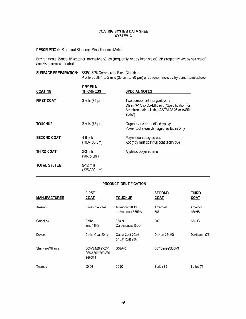
COATING SYSTEM DATA SHEET SYSTEM A1 DESCRIPTION: Structural Steel and Miscellaneous Metals Environmental Zones 1B (exterior, normally dry), 2A (frequently wet by fresh water), 2B (frequently wet by salt water), and 3B (chemical, neutral) SURFACE PREPARATION: SSPC-SP6 Commercial Blast Cleaning Profile depth 1 to 2 mils (25 µm to 50 µm) or as recommended by paint manufacturer DRY FILM COATING THICKNESS SPECIAL NOTES_____________________ FIRST COAT 3 mils (75 µm) Two component inorganic zinc Class "A" Slip Co-Efficient ("Specification for Structural Joints Using ASTM A325 or A490 Bolts") TOUCHUP 3 mils (75 µm) Organic zinc or modified epoxy Power tool clean damaged surfaces only SECOND COAT 4-6 mils Polyamide epoxy tie coat (100-150 µm) Apply by mist coat-full coat technique THIRD COAT 2-3 mils Aliphatic polyurethane (50-75 µm) TOTAL SYSTEM 9-12 mils (225-300 µm) PRODUCT IDENTIFICATION FIRST SECOND THIRD MANUFACTURER COAT TOUCHUP COAT COAT Ameron Dimetcote 21-9 Amercoat 68HS Amercoat Amercoat
or Amercoat 385PA 385 450HS
Carboline Carbo 858 or 893 134HS
Zinc 11HS Carbomastic 15LO
Devoe Catha-Coat 304V Catha-Coat 303H Devran 224HS Devthane 379
or Bar Rust 236
Sherwin-Williams B69VZ1/B69VZ3/ B69A45 B67 Series/B60V3
B65W301/B60V30
B69D11
Tnemec 90-96 90-97 Series 69 Series 74
-10
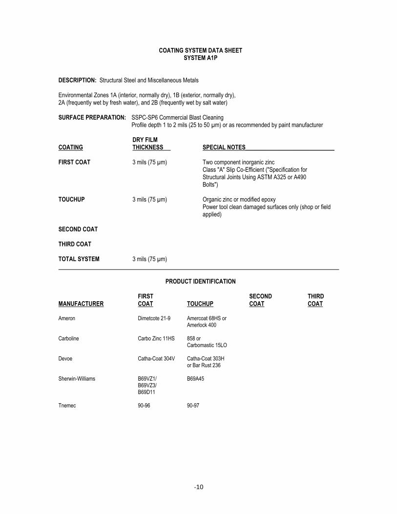
COATING SYSTEM DATA SHEET SYSTEM A1P DESCRIPTION: Structural Steel and Miscellaneous Metals Environmental Zones 1A (interior, normally dry), 1B (exterior, normally dry), 2A (frequently wet by fresh water), and 2B (frequently wet by salt water) SURFACE PREPARATION: SSPC-SP6 Commercial Blast Cleaning Profile depth 1 to 2 mils (25 to 50 µm) or as recommended by paint manufacturer DRY FILM COATING THICKNESS SPECIAL NOTES______________________________ FIRST COAT 3 mils (75 µm) Two component inorganic zinc Class "A" Slip Co-Efficient ("Specification for Structural Joints Using ASTM A325 or A490 Bolts") TOUCHUP 3 mils (75 µm) Organic zinc or modified epoxy Power tool clean damaged surfaces only (shop or field
applied) SECOND COAT THIRD COAT TOTAL SYSTEM 3 mils (75 µm) PRODUCT IDENTIFICATION FIRST SECOND THIRD MANUFACTURER COAT TOUCHUP COAT COAT Ameron Dimetcote 21-9 Amercoat 68HS or Amerlock 400 Carboline Carbo Zinc 11HS 858 or Carbomastic 15LO Devoe Catha-Coat 304V Catha-Coat 303H or Bar Rust 236 Sherwin-Williams B69VZ1/ B69A45 B69VZ3/ B69D11 Tnemec 90-96 90-97

-11
COATING SYSTEM DATA SHEET SYSTEM A8
DESCRIPTION: Ferrous Metal Surfaces Surface Temperatures from 200 F to 450 F (93 C to 232 C) SURFACE PREPARATION: SSPC-SP6 Commercial Blast Cleaning Profile depth 1 to 2 mils (25 to 50 µm) or as recommended by paint manufacturer DRY FILM COATING THICKNESS SPECIAL NOTES______________________________ FIRST COAT 3 mils (75 µm) Two component inorganic zinc primer TOUCHUP 3 mils (75 µm) Inorganic zinc rich primer Spot blast clean damaged surfaces only (shop or field
applied) SECOND COAT 1.5-2 mils Silicone aluminum (40-50 µm) THIRD COAT TOTAL SYSTEM 4.5-5 mils Follow manufacturer's instructions for curing (115-125 µm) PRODUCT IDENTIFICATION FIRST SECOND THIRD MANUFACTURER COAT TOUCHUP COAT COAT Ameron Dimetcote 21-9 Dimetcote 21-9 Amercoat 892HS Carboline Carbo Zinc 11HS Carbo Zinc 11HS 1248 Devoe Catha-Coat 304V Catha-Coat 304V HT-10 Sherwin-Williams B69AW9 B69AW9 100-A-518 Tnemec 90-96 90-96 39-661
-12
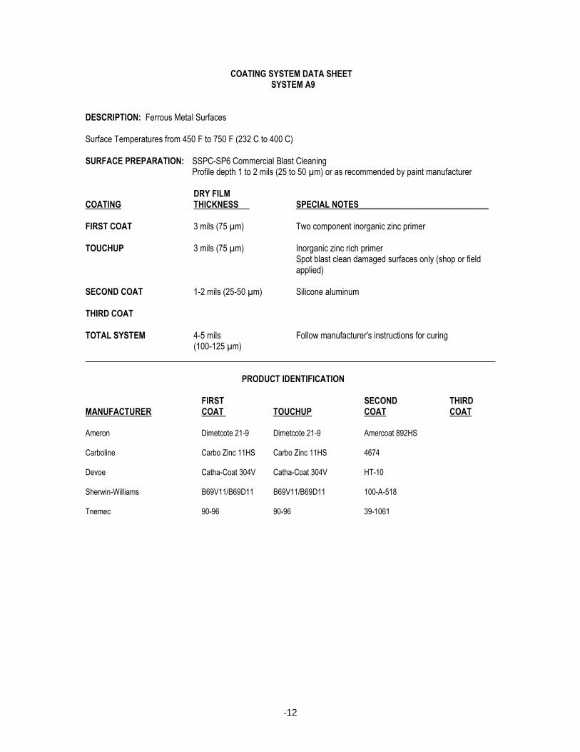
COATING SYSTEM DATA SHEET SYSTEM A9 DESCRIPTION: Ferrous Metal Surfaces Surface Temperatures from 450 F to 750 F (232 C to 400 C) SURFACE PREPARATION: SSPC-SP6 Commercial Blast Cleaning Profile depth 1 to 2 mils (25 to 50 µm) or as recommended by paint manufacturer DRY FILM COATING THICKNESS SPECIAL NOTES______________________________ FIRST COAT 3 mils (75 µm) Two component inorganic zinc primer TOUCHUP 3 mils (75 µm) Inorganic zinc rich primer Spot blast clean damaged surfaces only (shop or field
applied) SECOND COAT 1-2 mils (25-50 µm) Silicone aluminum THIRD COAT TOTAL SYSTEM 4-5 mils Follow manufacturer's instructions for curing (100-125 µm) PRODUCT IDENTIFICATION FIRST SECOND THIRD MANUFACTURER COAT TOUCHUP COAT COAT Ameron Dimetcote 21-9 Dimetcote 21-9 Amercoat 892HS Carboline Carbo Zinc 11HS Carbo Zinc 11HS 4674 Devoe Catha-Coat 304V Catha-Coat 304V HT-10 Sherwin-Williams B69V11/B69D11 B69V11/B69D11 100-A-518 Tnemec 90-96 90-96 39-1061
-13
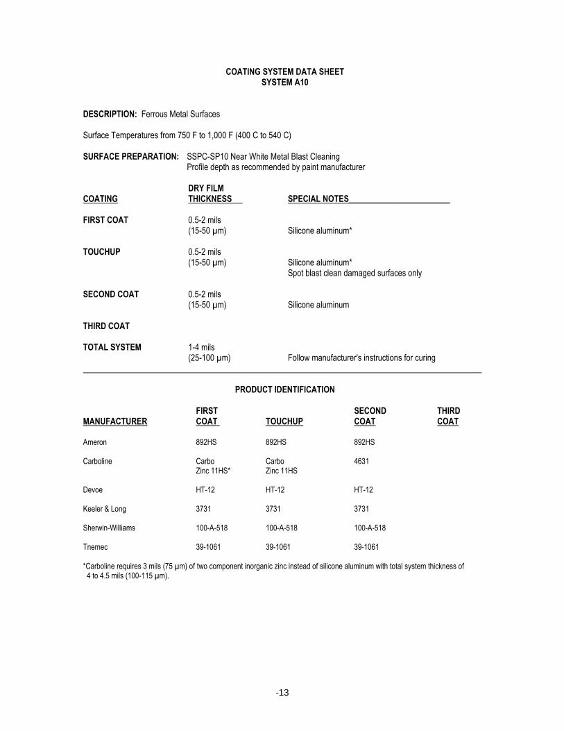
COATING SYSTEM DATA SHEET SYSTEM A10 DESCRIPTION: Ferrous Metal Surfaces Surface Temperatures from 750 F to 1,000 F (400 C to 540 C) SURFACE PREPARATION: SSPC-SP10 Near White Metal Blast Cleaning Profile depth as recommended by paint manufacturer DRY FILM COATING THICKNESS SPECIAL NOTES________________________ FIRST COAT 0.5-2 mils (15-50 µm) Silicone aluminum* TOUCHUP 0.5-2 mils (15-50 µm) Silicone aluminum* Spot blast clean damaged surfaces only SECOND COAT 0.5-2 mils (15-50 µm) Silicone aluminum THIRD COAT TOTAL SYSTEM 1-4 mils (25-100 µm) Follow manufacturer's instructions for curing PRODUCT IDENTIFICATION FIRST SECOND THIRD MANUFACTURER COAT TOUCHUP COAT COAT Ameron 892HS 892HS 892HS Carboline Carbo Carbo 4631 Zinc 11HS* Zinc 11HS Devoe HT-12 HT-12 HT-12 Keeler & Long 3731 3731 3731 Sherwin-Williams 100-A-518 100-A-518 100-A-518 Tnemec 39-1061 39-1061 39-1061 *Carboline requires 3 mils (75 µm) of two component inorganic zinc instead of silicone aluminum with total system thickness of 4 to 4.5 mils (100-115 µm).
-14
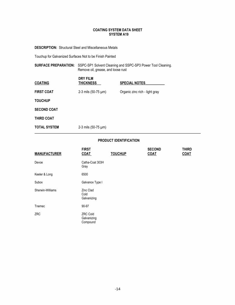
COATING SYSTEM DATA SHEET SYSTEM A19 DESCRIPTION: Structural Steel and Miscellaneous Metals Touchup for Galvanized Surfaces Not to be Finish Painted SURFACE PREPARATION: SSPC-SP1 Solvent Cleaning and SSPC-SP3 Power Tool Cleaning. Remove oil, grease, and loose rust DRY FILM COATING THICKNESS SPECIAL NOTES___________ FIRST COAT 2-3 mils (50-75 µm) Organic zinc rich - light gray TOUCHUP SECOND COAT THIRD COAT TOTAL SYSTEM 2-3 mils (50-75 µm) PRODUCT IDENTIFICATION FIRST SECOND THIRD MANUFACTURER COAT TOUCHUP COAT COAT Devoe Catha-Coat 303H Gray Keeler & Long 6500 Subox Galvanox Type I Sherwin-Williams Zinc Clad Cold Galvanizing Tnemec 90-97 ZRC ZRC Cold Galvanizing Compound
-15
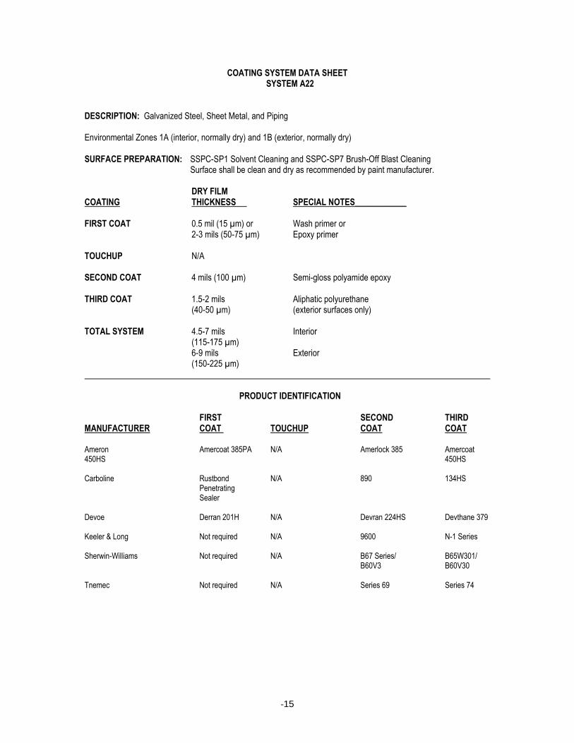
COATING SYSTEM DATA SHEET SYSTEM A22 DESCRIPTION: Galvanized Steel, Sheet Metal, and Piping Environmental Zones 1A (interior, normally dry) and 1B (exterior, normally dry) SURFACE PREPARATION: SSPC-SP1 Solvent Cleaning and SSPC-SP7 Brush-Off Blast Cleaning Surface shall be clean and dry as recommended by paint manufacturer. DRY FILM COATING THICKNESS SPECIAL NOTES____________ FIRST COAT 0.5 mil (15 µm) or Wash primer or 2-3 mils (50-75 µm) Epoxy primer TOUCHUP N/A SECOND COAT 4 mils (100 µm) Semi-gloss polyamide epoxy THIRD COAT 1.5-2 mils Aliphatic polyurethane (40-50 µm) (exterior surfaces only) TOTAL SYSTEM 4.5-7 mils Interior (115-175 µm) 6-9 mils Exterior (150-225 µm) PRODUCT IDENTIFICATION FIRST SECOND THIRD MANUFACTURER COAT TOUCHUP COAT COAT Ameron Amercoat 385PA N/A Amerlock 385 Amercoat 450HS 450HS Carboline Rustbond N/A 890 134HS Penetrating Sealer Devoe Derran 201H N/A Devran 224HS Devthane 379 Keeler & Long Not required N/A 9600 N-1 Series Sherwin-Williams Not required N/A B67 Series/ B65W301/ B60V3 B60V30 Tnemec Not required N/A Series 69 Series 74

-16
COATING SYSTEM DATA SHEET SYSTEM A25F DESCRIPTION: Shop Primed Ferrous Metal Surfaces (Architectural elements) Environmental Zones 1A (interior, normally dry) and 3D (chemical, mild) SURFACE PREPARATION: SSPC-SP3 Power Tool Cleaning of areas to be touchup painted; Clean and dry as
recommended by paint manufacturer DRY FILM COATING THICKNESS SPECIAL NOTES___________________ FIRST COAT Varies Shop applied. Spot test for adhesion TOUCHUP 2-3 mils Barrier coat (50-75 µm) SECOND COAT 2-3 mils Barrier coat (50-75 µm) THIRD COAT 4-6 mils Polyamide epoxy (100-150 µm) TOTAL SYSTEM 6-9 mils Not including shop applied first coat (150-225 µm) PRODUCT IDENTIFICATION FIRST SECOND THIRD MANUFACTURER COAT TOUCHUP COAT COAT Ameron N/A Amercoat 385PA Amercoat 385PA Amercoat 385 Carboline N/A 893 893 890 Devoe N/A Bar-Ox P-50 Bar-Ox P-50 Devran 224HS Low VOC Low VOC Keeler & Long N/A 9600 9600 9600 Sherwin-Williams N/A HSB50NZ3 HSB50NZ3 B67 Series/ B60V3 Tnemec N/A 163 163 163
-17
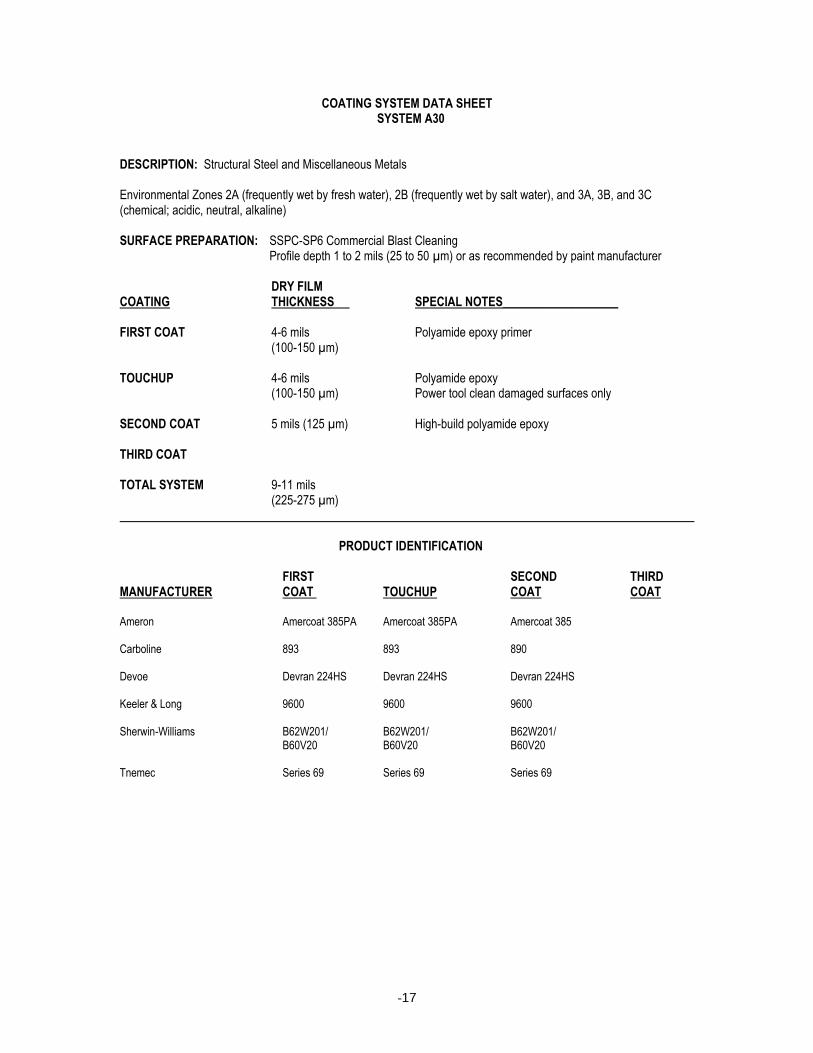
COATING SYSTEM DATA SHEET SYSTEM A30 DESCRIPTION: Structural Steel and Miscellaneous Metals Environmental Zones 2A (frequently wet by fresh water), 2B (frequently wet by salt water), and 3A, 3B, and 3C (chemical; acidic, neutral, alkaline) SURFACE PREPARATION: SSPC-SP6 Commercial Blast Cleaning Profile depth 1 to 2 mils (25 to 50 µm) or as recommended by paint manufacturer DRY FILM COATING THICKNESS SPECIAL NOTES___________________ FIRST COAT 4-6 mils Polyamide epoxy primer (100-150 µm) TOUCHUP 4-6 mils Polyamide epoxy (100-150 µm) Power tool clean damaged surfaces only SECOND COAT 5 mils (125 µm) High-build polyamide epoxy THIRD COAT TOTAL SYSTEM 9-11 mils (225-275 µm) PRODUCT IDENTIFICATION FIRST SECOND THIRD MANUFACTURER COAT TOUCHUP COAT COAT Ameron Amercoat 385PA Amercoat 385PA Amercoat 385 Carboline 893 893 890 Devoe Devran 224HS Devran 224HS Devran 224HS Keeler & Long 9600 9600 9600 Sherwin-Williams B62W201/ B62W201/ B62W201/ B60V20 B60V20 B60V20 Tnemec Series 69 Series 69 Series 69
-18
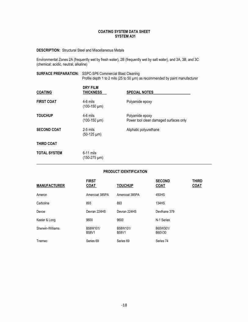
COATING SYSTEM DATA SHEET SYSTEM A31 DESCRIPTION: Structural Steel and Miscellaneous Metals Environmental Zones 2A (frequently wet by fresh water), 2B (frequently wet by salt water), and 3A, 3B, and 3C (chemical; acidic, neutral, alkaline) SURFACE PREPARATION: SSPC-SP6 Commercial Blast Cleaning Profile depth 1 to 2 mils (25 to 50 µm) as recommended by paint manufacturer DRY FILM COATING THICKNESS SPECIAL NOTES____________________ FIRST COAT 4-6 mils Polyamide epoxy (100-150 µm) TOUCHUP 4-6 mils Polyamide epoxy (100-150 µm) Power tool clean damaged surfaces only SECOND COAT 2-5 mils Aliphatic polyurethane (50-125 µm) THIRD COAT TOTAL SYSTEM 6-11 mils (150-275 µm) PRODUCT IDENTIFICATION FIRST SECOND THIRD MANUFACTURER COAT TOUCHUP COAT COAT Ameron Amercoat 385PA Amercoat 385PA 450HS Carboline 893 893 134HS Devoe Devran 224HS Devran 224HS Devthane 379 Keeler & Long 9600 9600 N-1 Series Sherwin-Williams B58W101/ B58W101/ B65W301/ B58V1 B58V1 B60V30 Tnemec Series 69 Series 69 Series 74
-19
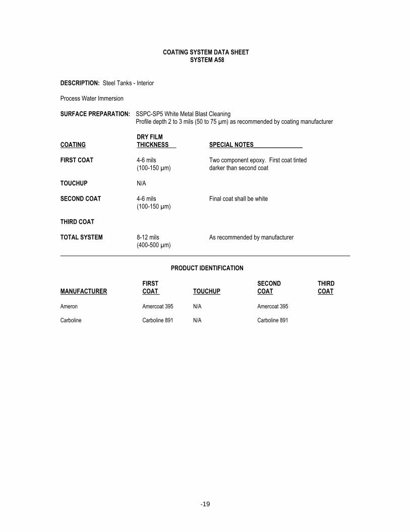
COATING SYSTEM DATA SHEET SYSTEM A58 DESCRIPTION: Steel Tanks - Interior Process Water Immersion SURFACE PREPARATION: SSPC-SP5 White Metal Blast Cleaning Profile depth 2 to 3 mils (50 to 75 µm) as recommended by coating manufacturer DRY FILM COATING THICKNESS SPECIAL NOTES________________ FIRST COAT 4-6 mils Two component epoxy. First coat tinted (100-150 µm) darker than second coat TOUCHUP N/A SECOND COAT 4-6 mils Final coat shall be white (100-150 µm) THIRD COAT TOTAL SYSTEM 8-12 mils As recommended by manufacturer (400-500 µm) PRODUCT IDENTIFICATION FIRST SECOND THIRD MANUFACTURER COAT TOUCHUP COAT COAT Ameron Amercoat 395 N/A Amercoat 395 Carboline Carboline 891 N/A Carboline 891

-20
COATING SYSTEM DATA SHEET SYSTEM C1 DESCRIPTION: Concrete and Concrete Masonry SURFACE PREPARATION: Clean, dry, and free of contaminants as recommended by paint manufacturer DRY FILM COATING THICKNESS SPECIAL NOTES________________________ FIRST COAT Varies Masonry filler applied at rate recommended by
manufacturer TOUCHUP N/A SECOND COAT 2-3 mils Acrylic latex (low gloss) (50-75 µm) THIRD COAT 2-3 mils Acrylic latex (low gloss) (50-75 µm) TOTAL SYSTEM 4-6 mils Not including masonry filler (100-150 µm) PRODUCT IDENTIFICATION FIRST SECOND THIRD MANUFACTURER COAT TOUCHUP COAT COAT Ameron Amerlock 400BF N/A Amercoat 220 SA Amercoat 220 SA Carboline Flexxide N/A 3359 3359 Block Filler Devoe Bloxfil 52901 N/A Devflex 605 Devflex 605 Keeler & Long 6440 N/A K-3 Series K-3 Series Sherwin-Williams B61W2 N/A B66W1 B66W1 Tnemec Series 130 N/A Series 6 Series 6
-21
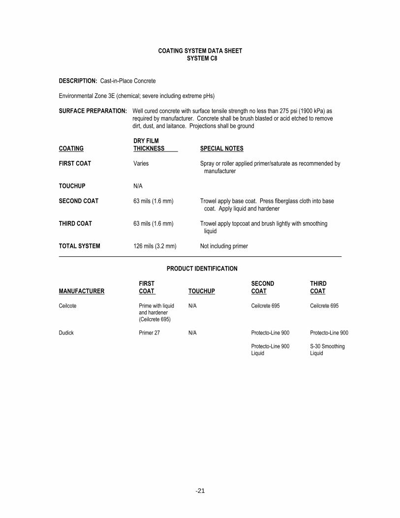
COATING SYSTEM DATA SHEET SYSTEM C8 DESCRIPTION: Cast-in-Place Concrete Environmental Zone 3E (chemical; severe including extreme pHs) SURFACE PREPARATION: Well cured concrete with surface tensile strength no less than 275 psi (1900 kPa) as
required by manufacturer. Concrete shall be brush blasted or acid etched to remove dirt, dust, and laitance. Projections shall be ground
DRY FILM COATING THICKNESS SPECIAL NOTES FIRST COAT Varies Spray or roller applied primer/saturate as recommended by
manufacturer TOUCHUP N/A SECOND COAT 63 mils (1.6 mm) Trowel apply base coat. Press fiberglass cloth into base
coat. Apply liquid and hardener THIRD COAT 63 mils (1.6 mm) Trowel apply topcoat and brush lightly with smoothing
liquid TOTAL SYSTEM 126 mils (3.2 mm) Not including primer PRODUCT IDENTIFICATION FIRST SECOND THIRD MANUFACTURER COAT TOUCHUP COAT COAT Ceilcote Prime with liquid N/A Ceilcrete 695 Ceilcrete 695 and hardener (Ceilcrete 695) Dudick Primer 27 N/A Protecto-Line 900 Protecto-Line 900 Protecto-Line 900 S-30 Smoothing Liquid Liquid
-22
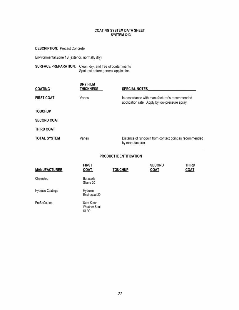
COATING SYSTEM DATA SHEET SYSTEM C13 DESCRIPTION: Precast Concrete Environmental Zone 1B (exterior, normally dry) SURFACE PREPARATION: Clean, dry, and free of contaminants Spot test before general application DRY FILM COATING THICKNESS SPECIAL NOTES___________________________ FIRST COAT Varies In accordance with manufacturer's recommended
application rate. Apply by low-pressure spray TOUCHUP SECOND COAT THIRD COAT TOTAL SYSTEM Varies Distance of rundown from contact point as recommended
by manufacturer PRODUCT IDENTIFICATION FIRST SECOND THIRD MANUFACTURER COAT TOUCHUP COAT COAT Chemstop Baracade Silane 20 Hydrozo Coatings Hydrozo Enviroseal 20 ProSoCo, Inc. Sure Klean Weather Seal SL2O
-23
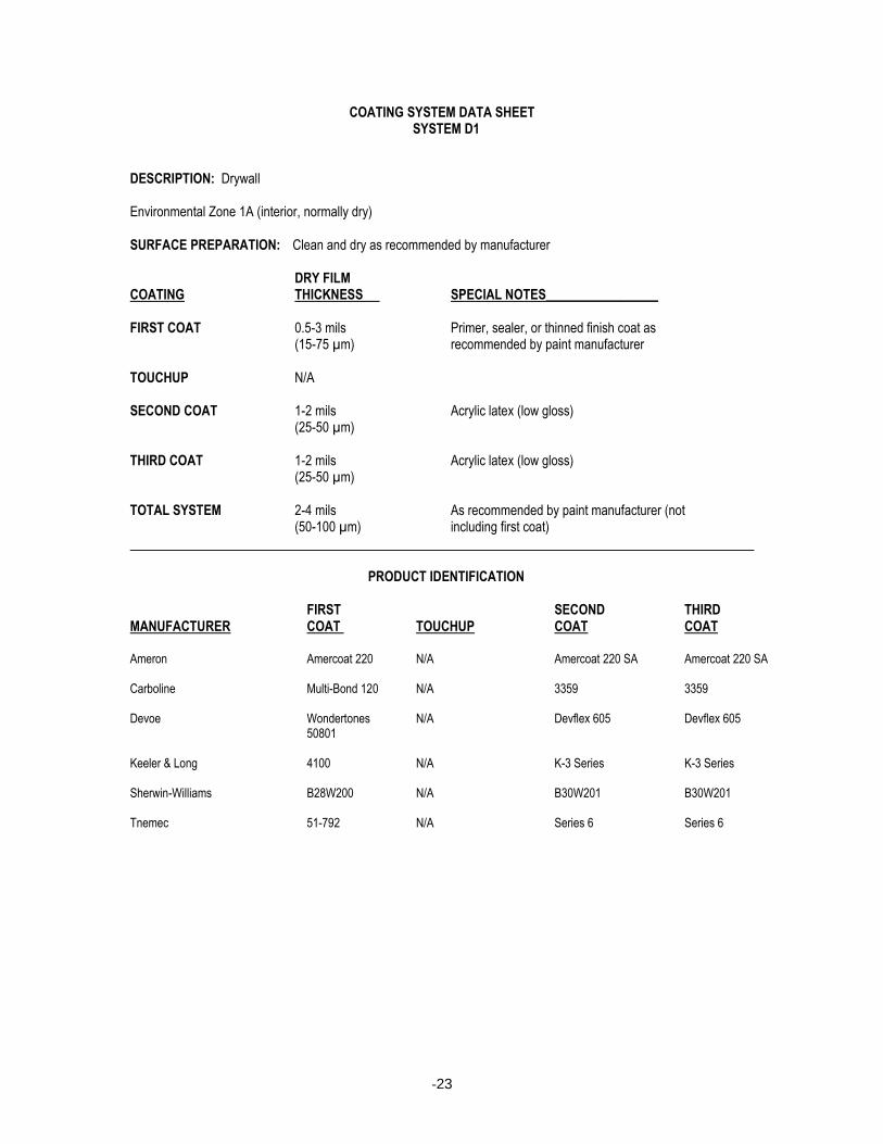
COATING SYSTEM DATA SHEET SYSTEM D1 DESCRIPTION: Drywall Environmental Zone 1A (interior, normally dry) SURFACE PREPARATION: Clean and dry as recommended by manufacturer DRY FILM COATING THICKNESS SPECIAL NOTES_________________ FIRST COAT 0.5-3 mils Primer, sealer, or thinned finish coat as (15-75 µm) recommended by paint manufacturer TOUCHUP N/A SECOND COAT 1-2 mils Acrylic latex (low gloss) (25-50 µm) THIRD COAT 1-2 mils Acrylic latex (low gloss) (25-50 µm) TOTAL SYSTEM 2-4 mils As recommended by paint manufacturer (not (50-100 µm) including first coat) PRODUCT IDENTIFICATION FIRST SECOND THIRD MANUFACTURER COAT TOUCHUP COAT COAT Ameron Amercoat 220 N/A Amercoat 220 SA Amercoat 220 SA Carboline Multi-Bond 120 N/A 3359 3359 Devoe Wondertones N/A Devflex 605 Devflex 605 50801 Keeler & Long 4100 N/A K-3 Series K-3 Series Sherwin-Williams B28W200 N/A B30W201 B30W201 Tnemec 51-792 N/A Series 6 Series 6

-24
COATING SYSTEM DATA SHEET SYSTEM E12 DESCRIPTION: Mechanical Equipment Ferrous Surfaces Subject to Corrosion Which Should Not Be Painted SURFACE PREPARATION: SSPC-SP6 Commercial Blast Cleaning Profile depth as recommended by coating manufacturer DRY FILM COATING THICKNESS SPECIAL NOTES_______________________________ FIRST COAT Varies Water soluble preservative TOUCHUP SECOND COAT THIRD COAT TOTAL SYSTEM Varies Coating thickness and application as recommended by
coating manufacturer PRODUCT IDENTIFICATION FIRST SECOND THIRD MANUFACTURER COAT TOUCHUP COAT COAT Ardrox 228-M Dubois 200
-25
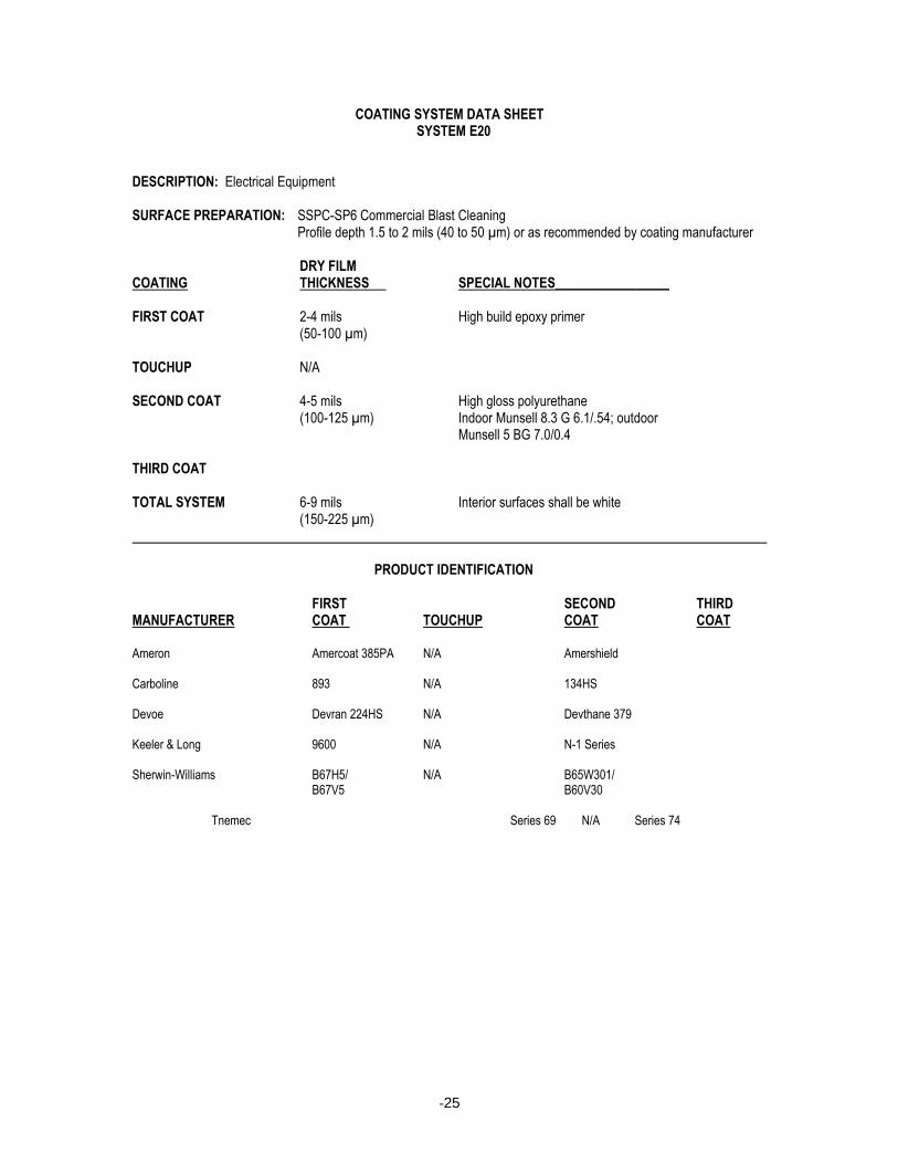
COATING SYSTEM DATA SHEET SYSTEM E20 DESCRIPTION: Electrical Equipment SURFACE PREPARATION: SSPC-SP6 Commercial Blast Cleaning Profile depth 1.5 to 2 mils (40 to 50 µm) or as recommended by coating manufacturer DRY FILM COATING THICKNESS SPECIAL NOTES_________________ FIRST COAT 2-4 mils High build epoxy primer (50-100 µm) TOUCHUP N/A SECOND COAT 4-5 mils High gloss polyurethane (100-125 µm) Indoor Munsell 8.3 G 6.1/.54; outdoor Munsell 5 BG 7.0/0.4 THIRD COAT TOTAL SYSTEM 6-9 mils Interior surfaces shall be white (150-225 µm) PRODUCT IDENTIFICATION FIRST SECOND THIRD MANUFACTURER COAT TOUCHUP COAT COAT Ameron Amercoat 385PA N/A Amershield Carboline 893 N/A 134HS Devoe Devran 224HS N/A Devthane 379 Keeler & Long 9600 N/A N-1 Series Sherwin-Williams B67H5/ N/A B65W301/ B67V5 B60V30
Tnemec Series 69 N/A Series 74
-26
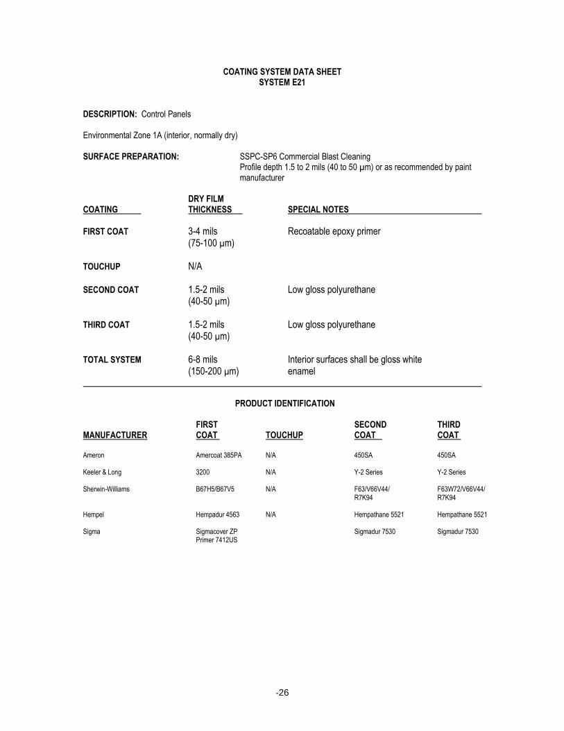
COATING SYSTEM DATA SHEET SYSTEM E21
DESCRIPTION: Control Panels Environmental Zone 1A (interior, normally dry) SURFACE PREPARATION: SSPC-SP6 Commercial Blast Cleaning Profile depth 1.5 to 2 mils (40 to 50 µm) or as recommended by paint
manufacturer DRY FILM COATING THICKNESS SPECIAL NOTES
FIRST COAT 3-4 mils Recoatable epoxy primer (75-100 µm) TOUCHUP N/A SECOND COAT 1.5-2 mils Low gloss polyurethane (40-50 µm) THIRD COAT 1.5-2 mils Low gloss polyurethane (40-50 µm) TOTAL SYSTEM 6-8 mils Interior surfaces shall be gloss white (150-200 µm) enamel PRODUCT IDENTIFICATION FIRST SECOND THIRD MANUFACTURER COAT TOUCHUP COAT COAT Ameron Amercoat 385PA N/A 450SA 450SA Keeler & Long 3200 N/A Y-2 Series Y-2 Series Sherwin-Williams B67H5/B67V5 N/A F63/V66V44/ F63W72/V66V44/ R7K94 R7K94 Hempel Hempadur 4563 N/A Hempathane 5521 Hempathane 5521 Sigma Sigmacover ZP Sigmadur 7530 Sigmadur 7530 Primer 7412US

-27
COATING SYSTEM DATA SHEET SYSTEM E45
DESCRIPTION: Miscellaneous Equipment Environmental Zones 1B (exterior, normally dry), and 3A, 3B, and 3C (chemical; acidic, neutral, alkaline) SURFACE PREPARATION: SSPC-SP6 Commercial Blast Cleaning Profile depth 1 to 2 mils (25 to 50 µm) as recommended by paint
manufacturer DRY FILM COATING THICKNESS SPECIAL NOTES FIRST COAT 3-5 mils Rust-inhibitive epoxy primer (75-125 µm) TOUCHUP N/A SECOND COAT 1.5-2 mils Aliphatic polyurethane (40-50 µm) THIRD COAT TOTAL SYSTEM 4.5-7 mils (115-175 µm) PRODUCT IDENTIFICATION FIRST SECOND THIRD MANUFACTURER COAT TOUCHUP COAT COAT Ameron Amercoat 370 N/A Amercoat 450HS Carboline 893RCP N/A 134HS Devoe Devran 224HS N/A Devthane 379 Keeler & Long 3200 N/A N-1 Series Sherwin-Williams B67H5/ N/A B65W301/ B67V5 B60V30 Tnemec 65-1211 N/A Series 74 Hempel Hempadur 1556 N/A Hempathane 55 Series International Interseal 670 N/A Interthane 990
CSDS E45 - 031898
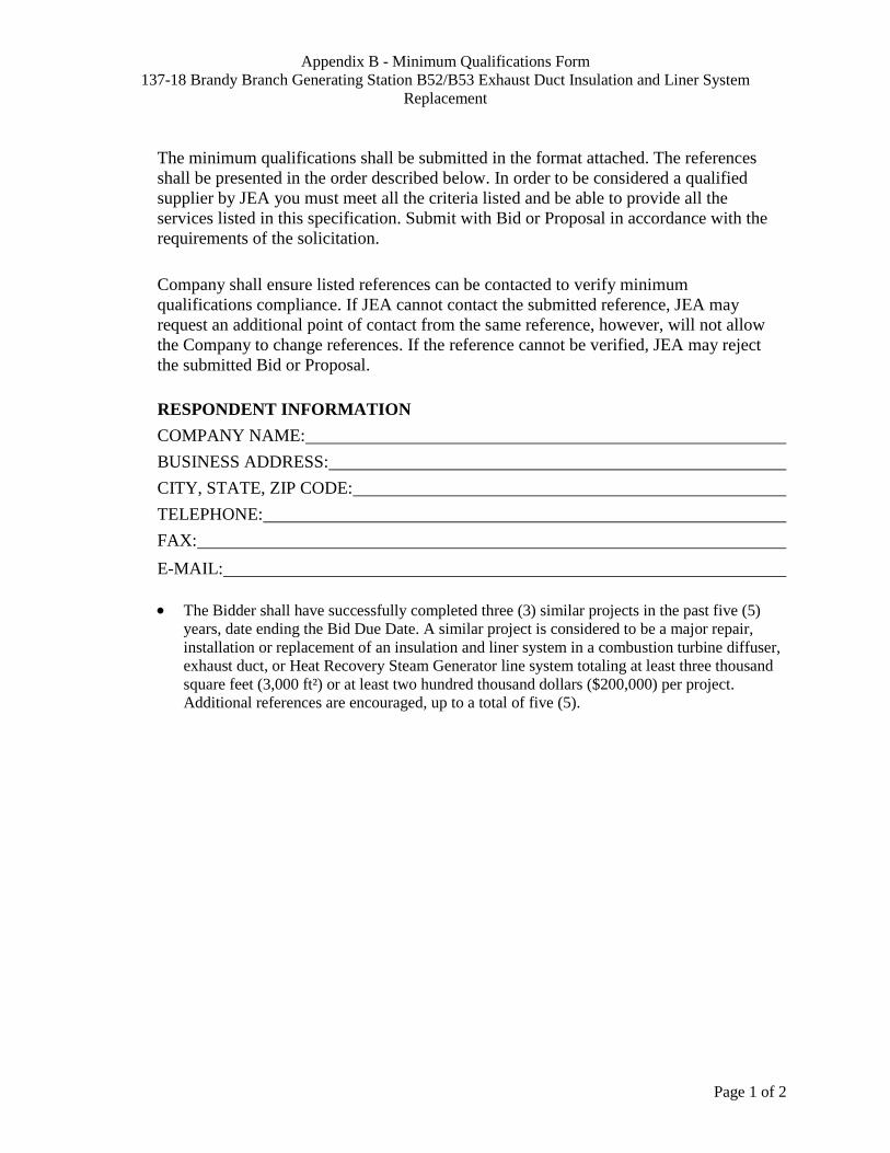
Appendix B - Minimum Qualifications Form
137-18 Brandy Branch Generating Station B52/B53 Exhaust Duct Insulation and Liner System
Replacement
Page 1 of 2
The minimum qualifications shall be submitted in the format attached. The references
shall be presented in the order described below. In order to be considered a qualified
supplier by JEA you must meet all the criteria listed and be able to provide all the
services listed in this specification. Submit with Bid or Proposal in accordance with the
requirements of the solicitation.
Company shall ensure listed references can be contacted to verify minimum
qualifications compliance. If JEA cannot contact the submitted reference, JEA may
request an additional point of contact from the same reference, however, will not allow
the Company to change references. If the reference cannot be verified, JEA may reject
the submitted Bid or Proposal.
RESPONDENT INFORMATION
COMPANY NAME:
BUSINESS ADDRESS:
CITY, STATE, ZIP CODE:
TELEPHONE:
FAX:
E-MAIL:
The Bidder shall have successfully completed three (3) similar projects in the past five (5)
years, date ending the Bid Due Date. A similar project is considered to be a major repair,
installation or replacement of an insulation and liner system in a combustion turbine diffuser,
exhaust duct, or Heat Recovery Steam Generator line system totaling at least three thousand
square feet (3,000 ft²) or at least two hundred thousand dollars ($200,000) per project.
Additional references are encouraged, up to a total of five (5).
Appendix B - Minimum Qualifications Form
137-18 Brandy Branch Generating Station B52/B53 Exhaust Duct Insulation and Liner System
Replacement
Page 2 of 2
Reference ____ of ____
Primary Nature of Service Provided:
Location:
Customer:
Reference Name:
Reference Phone Number:
Email Address:
Project Value:
Description of Project:
______________________________________________________________________________
______________________________________________________________________________
______________________________________________________________________________
______________________________________________________________________________
______________________________________________________________________________
______________________________________________________________________________
______________________________________________________________________________
______________________________________________________________________________
______________________________________________________________________________
______________________________________________________________________________
______________________________________________________________________________
______________________________________________________________________________
______________________________________________________________________________
______________________________________________________________________________
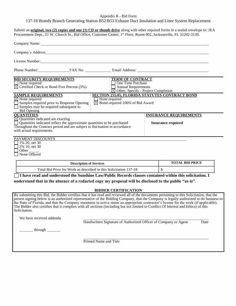
Appendix B - Bid Form
137-18 Brandy Branch Generating Station B52/B53 Exhaust Duct Insulation and Liner System Replacement
Submit an original, two (2) copies and one (1) CD or thumb drive along with other required forms in a sealed envelope to: JEA
Procurement Dept., 21 W. Church St., Bid Office, Customer Center, 1st Floor, Room 002, Jacksonville, FL 32202-3139.
Company Name:
Company’s Address
License Number:
Phone Number: FAX No: Email Address:
BID SECURITY REQUIREMENTS TERM OF CONTRACT None required One Time Purchase Certified Check or Bond Five Percent (5%) Annual Requirements
Other, Specify - Project Completion
SAMPLE REQUIREMENTS SECTION 255.05, FLORIDA STATUTES CONTRACT BOND None required None required Samples required prior to Response Opening Bond required 100% of Bid Award Samples may be required subsequent to
Bid Opening
QUANTITIES INSURANCE REQUIREMENTS Quantities indicated are exacting Quantities indicated reflect the approximate quantities to be purchased Insurance required
Throughout the Contract period and are subject to fluctuation in accordance with actual requirements.
PAYMENT DISCOUNTS 1% 20, net 30 2% 10, net 30 Other None Offered
Description of Services TOTAL BID PRICE
Total Bid Price for Work as described in this Solicitation 137-18 $
I have read and understood the Sunshine Law/Public Records clauses contained within this solicitation. I
understand that in the absence of a redacted copy my proposal will be disclosed to the public “as-is”.
BIDDER CERTIFICATION
By submitting this Bid, the Bidder certifies that it has read and reviewed all of the documents pertaining to this Solicitation, that the person signing below is an authorized representative of the Bidding Company, that the Company is legally authorized to do business in the State of Florida, and that the Company maintains in active status an appropriate contractor’s license for the work (if applicable). The Bidder also certifies that it complies with all sections (including but not limited to Conflict Of Interest and Ethics) of this Solicitation.
We have received addenda Handwritten Signature of Authorized Officer of Company or Agent Date
_______ through _______
Printed Name and Title