Embed Size (px)
Citation preview

2 0 0 9 E d i t i o n
tyton®
fittings for WatEr & WastEWatEr, firE ProtEction & industrial aPPlications
14"-24"
NSF®
Certified toANSI/NSF 61

u.s. PiPE and foundry co. tyton® fittings Bro-004 REVISED 03.09
tyton®
fittingsNSF®
Certified toANSI/NSF 61
P 2866.
DIP.
PIPE
2 0 0 9 E d i t i o n
table of contentsTYTON Fittings 3
Assembly of TYTON Fittings 4
Bell Dimensions 6
Thickness and Dimensions 90° Bends 7 45° Bends 8 22-1/2° Bends 9 30° Bends 9 11-1/4° Bends 10 5-5/8° Bends 11 Tees and Crosses 12 Flanged Outlet Tees 14 Bell x Bell Concentric Reducers, 14"-24" 16 Large End Bell and Small End Bell Concentric Reducers, 14"-24" 17 TYTON Plugs 19
Products for Water, Waste Water, and Fire Protection 20

tyton®
fittingsNSF®
Certified toANSI/NSF 61
P 3866.
DIP.
PIPE
2 0 0 9 E d i t i o n
REVISED 03.09u.s. PiPE and foundry co. tyton® fittings Bro-004
TYTON JOINT® Pipe (push-on) has become so popular since its introduction in 1956 that it now constitutes more than 95% of the pipe shipped by U.S. Pipe. In 1965, U.S. Pipe introduced 4"–12"* TYTON® Fittings. Later, U.S. Pipe introduced 14"–24". TYTON Fittings are also produced in metric diameters for the international market. (See U.S. Pipe’s International Catalog.)
Fittings shall be push-on joint Ductile Iron fittings with a pressure rating of 350 psi for 14"–24" fittings. Fittings shall be in accordance with all applicable requirements of ANSI/AWWA C110/A21.10 or ANSI/AWWA C153/A21.53 with the exception of the manufacturer’s proprietary design dimensions. Joint components shall be in accordance with the requirements for push-on joints in ANSI/AWWA C111/A21.11.
*4"–12" sizes are now furnished as TRIM TYTON ® Fittings. A separate brochure is available upon request.
NotE: If specifiers and users believe that corrosive soils will be encountered where our products are to be installed, please refer to ANSI/AWWA C105/A21.5, Polyethylene Encasement for Ductile Iron Piping Systems, for proper external protection procedures.
PERMAFUSE®, TRIM TYTON®, TYTON®, TYTON JOINT®, TR FLEX® and FIELD LOK 350® are registered trademarks of U.S. Pipe and Foundry Company.
restrained JointsInstant joint restraint can be obtained for TYTON Fittings and TYTON JOINT® Pipe, sizes 14"–24", with the use of FIELD LOK 350® Gaskets for 14"–24". With insertion of a FIELD LOK 350 Gasket joint restraint is provided for maximum working pressure of 350 psi for 14"–24". The FIELD LOK Gasket systems provide a fast and unique means of joint restraint without the need for thrust or “kicker” blocks, bolts, grooves, rods, clamps or retainer glands, thus resulting in a savings of labor, material and time.
CAUtIoN: U.S. Pipe does not recommend FIELD LOK 350® Gaskets for use above ground. The long-term effect of cyclical movements can be gradual joint separation to the point that the seal on the gasket bulb is compromised. Sources of cyclical movements include vibration as may be found on bridge crossings, pressure surges from pumping operations, and thermal expansion and contraction resulting from atmospheric temperature changes. These conditions are not experienced with buried pipelines.
tyton fittings
ANSI/AWWA C110/A21.10, Ductile Iron and Gray Iron Fittings 3"–48" (75 mm–1200 mm), for Water.
ANSI/AWWA C153/A21.53, American National Standard for Ductile Iron Compact Fittings for Water Service.
ANSI/AWWA C111/A21.11, Rubber Gasket Joints for Ductile Iron Pressure Pipe and Fittings.
Rubber gasketed push-on joint fittings conform to and meet all the requirements for push-on joints in ANSI/AWWA C111/A21.11.Gaskets are normally furnished with TYTON Fittings.
AStM A536 "Standard Specification for Ductile Iron Castings."
ansi /aWWa standards

tyton®
fittingsNSF®
Certified toANSI/NSF 61
P 4866.
DIP.
PIPE
2 0 0 9 E d i t i o n
REVISED 03.09u.s. PiPE and foundry co. tyton® fittings Bro-004
Inspect gasket, socket and spigot for cleanliness. Remove any foreign matter and excessive coating. When pipe is cut in the field, the cut end can be readily conditioned with a bevel so that it may be used to make up the joint. The outside of the cut end should be tapered back about 1/4-inch at an angle of about 30 degrees with the center line of the pipe. This can be done quite easily with a portable grinder. Remove any sharp, rough edges which might injure the gasket.
Insert the TYTON® Gasket into the bell socket, large or bulb end of the gasket entering first. A small loop or V-shaped fold in the gasket will facilitate its entry. For sizes 14"-24", it may be helpful to loop the gasket two or more times. Check that the heel of the gasket is uniformly seated and does not protrude above the bell throat into the pipe way. A thin film of TYTON JOINT® Lubricant should be applied to the inside surface of the gasket which will come in contact with the beveled end of the pipe. In warm, dry weather conditions, the lubricant can dry out, especially when applied to warm or hot pipe, it will be necessary to add a small amount of water to hydrate the lubricant. Only TYTON JOINT Lubricant should be used.
CAUtIoN: the use of spray-on lubricant is not recommended. Experience has determined that spray-on lubricant may not have sufficient lubricity to allow joint assembly without gasket displacement.
The plain end of the pipe must be cleaned of all foreign matter on the outside from the end to the stripes. Frozen materials may cling to the pipe in cold weather and must be removed. Apply a thin film of lubricant to the outside of the plain end for about 3 inches back from the end. Do not allow the plain end to touch the ground or trench side after lubricating since foreign matter may adhere to the lubricant and cause a leak. Lubricant other than that furnished with the pipe should not be used.
The fitting and the pipe must be aligned and the spigot entered into the socket until it just makes contact with the gasket. This is the starting position for the assembly of the joint. Joint assembly should then be continued by forcing the spigot of the entering pipe past the gasket (which is thereby compressed) until the first painted stripe has disappeared into the socket and the front edge of the second stripe is approx imately flush with the bell face. If the assembly is not accomplished with the application of reasonable force, the plain end of the pipe should be removed to check for the proper positioning of the gasket. Keep the joint in alignment during assembly.
A feeler gage may be inserted between the bell and the plain end of the assembled joint to verify the position of the gasket. When the gage encounters the gasket, increased resistance will be felt. Note the depth of insertion of the gage. Continue probing around the periphery of the joint, noting the depth to resistance each time. If the depth of insertion is uniform, the gasket has remained in place. If, at any point, the depth of insertion increases significantly, this indicates a dislodged gasket. The joint should be disassembled, thoroughly cleaned with water, and examined for any condition that might have caused the gasket to become dislodged before attempting to reassemble the joint.
assembly of tyton fittings
NotE: Care must be taken not to damage products furnished with special coatings or polyethylene encasement.

tyton®
fittingsNSF®
Certified toANSI/NSF 61
P 5866.
DIP.
PIPE
2 0 0 9 E d i t i o n
REVISED 03.09u.s. PiPE and foundry co. tyton® fittings Bro-004
assembly of tyton fittings (cont.)
SIZE Bell Choker Sling Inches Inches
14 –20 3/8 Dia x 84 long
24 3/8 Dia x 120 long
tools needed for assembly of 14"-24" tyton fittings: The photograph to the right shows assembly tools if the installer prefers to use come-alongs to assemble 14"–24" fittings.
Two (2) 1-1/2 ton chain hoists with 25 feet of chain, two (2) bell choker slings of the size indicated in the table to the right.
Some installers may prefer assembling TYTON Fittings with a backhoe. If this is done, care should be taken not to damage the gasket, pipe or fitting. A timber between the backhoe bucket and the fitting will help to prevent such damage. Caution: Avoid “slamming” the fitting home to prevent damage to lining material inside the bell at the back of the socket.

tyton®
fittingsNSF®
Certified toANSI/NSF 61
P 6866.
DIP.
PIPE
2 0 0 9 E d i t i o n
REVISED 03.09u.s. PiPE and foundry co. tyton® fittings Bro-004
SIZE A B
14 18.12 5.00
16 20.32 5.00
18 22.52 5.00
20 24.74 5.00
24 30.14 5.00
Bell dimensions
DimensionsInches
Inches
NotE: For Bell Dimensions of TYTON JOINT ® Pipe, reference U.S. Pipe’s TYTON JOINT Pipe Brochure.
Actual bell configuration may vary from illustration shown.
For 12" and smaller fittings of this configuration, please reference U.S. Pipe’s TRIM TYTON® Fittings brochure.
Sizes 14"–24"
B
Size
tyton®
fittingsNSF®
Certified toANSI/NSF 61
P 7866.
DIP.
PIPE
2 0 0 9 E d i t i o n
REVISED 03.09u.s. PiPE and foundry co. tyton® fittings Bro-004
PRESSURE
DIMENSIoNS WEIGht
SIZE RAtING Inches Pounds
Inches psi t A R BxB
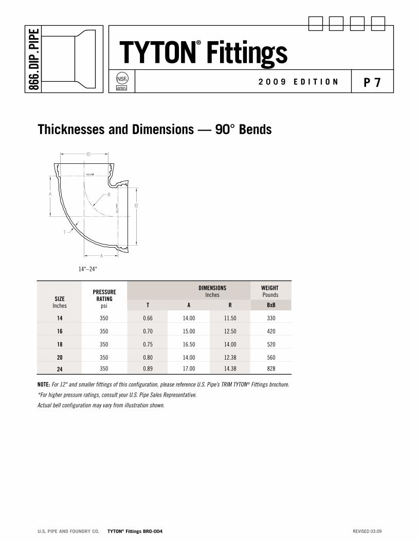
14 350 0.66 14.00 11.50 330
16 350 0.70 15.00 12.50 420
18 350 0.75 16.50 14.00 520
20 350 0.80 14.00 12.38 560
24 350 0.89 17.00 14.38 828
NotE: For 12" and smaller fittings of this configuration, please reference U.S. Pipe’s TRIM TYTON® Fittings brochure.
*For higher pressure ratings, consult your U.S. Pipe Sales Representative.
Actual bell configuration may vary from illustration shown.
thicknesses and dimensions — 90° Bends
14"–24"

tyton®
fittingsNSF®
Certified toANSI/NSF 61
P 8866.
DIP.
PIPE
2 0 0 9 E d i t i o n
REVISED 03.09u.s. PiPE and foundry co. tyton® fittings Bro-004
thicknesses and dimensions — 45° Bends
14"–24"
PRESSURE
DIMENSIoNS WEIGht
SIZE RAtING Inches Pounds
Inches psi t A R BxB
14 350 0.66 7.50 12.06 265
16 350 0.70 8.00 13.25 330
18 350 0.75 8.50 14.50 400
20 350 0.80 9.50 16.88 505
24 350 0.89 6.00 14.00 536
NotE: For 12" and smaller fittings of this configuration, please reference U.S. Pipe’s TRIM TYTON ® Fittings brochure.
*For higher pressure ratings, consult your U.S. Pipe Sales Representative.
Actual bell configuration may vary from illustration shown.

tyton®
fittingsNSF®
Certified toANSI/NSF 61
P 9866.
DIP.
PIPE
2 0 0 9 E d i t i o n
REVISED 03.09u.s. PiPE and foundry co. tyton® fittings Bro-004
PRESSURE
DIMENSIoNS WEIGht
SIZE RAtING Inches Pounds
Inches psi t A R BxB
24 350 0.89 8.00 21.01 613
*For higher pressure ratings, consult your U.S. Pipe Sales Representative. Actual bell configuration may vary from illustration shown.
thicknesses and dimensions — 30° Bends
PRESSURE
DIMENSIoNS WEIGht
SIZE RAtING Inches Pounds
Inches psi t A R BxB
14 350 0.66 7.50 25.12 265
16 350 0.70 8.00 27.62 335
18 350 0.75 8.50 30.19 405
20 350 0.80 9.50 35.19 510
24 350 0.89 4.50 14.45 493
NotE: For 12" and smaller fittings of this configuration, please reference U.S. Pipe’s TRIM TYTON® Fittings brochure. *For higher pressure ratings, consult your U.S. Pipe Sales Representative. Actual bell configuration may vary from illustration shown.
thicknesses and dimensions — 22-1/2° Bends
14"–24"

tyton®
fittingsNSF®
Certified toANSI/NSF 61
P 10866.
DIP.
PIPE
2 0 0 9 E d i t i o n
REVISED 03.09u.s. PiPE and foundry co. tyton® fittings Bro-004
PRESSURE
DIMENSIoNS WEIGht
SIZE RAtING Inches Pounds
Inches psi t A R BxB
14 350 0.66 7.50 50.75 270
16 350 0.70 8.00 55.81 340
18 350 0.75 8.50 60.94 405
20 350 0.80 9.50 71.06 515
24 350 0.89 3.00 13.96 440
NotE: For 12" and smaller fittings of this configuration, please reference U.S. Pipe’s TRIM TYTON® Fittings brochure.
*For higher pressure ratings, consult your U.S. Pipe Sales Representative.
Actual bell configuration may vary from illustration shown.
thicknesses and dimensions — 11-1/4° Bends
14"–24"

tyton®
fittingsNSF®
Certified toANSI/NSF 61
P 11866.
DIP.
PIPE
2 0 0 9 E d i t i o n
REVISED 03.09u.s. PiPE and foundry co. tyton® fittings Bro-004
PRESSURE
DIMENSIoNS WEIGht
SIZE RAtING Inches Pounds
Inches psi t A R BxB
16 350 0.70 6.00 60.00 280
20 350 0.80 5.00 57.59 395
24 350 0.89 6.00 73.87 547
*For higher pressure ratings, consult your U.S. Pipe Sales Representative.
Actual bell configuration may vary from illustration shown.
thicknesses and dimensions — 5-5/8° Bends
16" - 24"

tyton®
fittingsNSF®
Certified toANSI/NSF 61
P 12866.
DIP.
PIPE
2 0 0 9 E d i t i o n
REVISED 03.09u.s. PiPE and foundry co. tyton® fittings Bro-004
thicknesses and dimensions — tees and crosses
PRESSURE WEIGht SIZE RAtING DIMENSIoNS Pounds Inches psi Inches tEES CRoSSES
RUN BRANCh t t1 h J S R BxBxB BxBxBxB
14 6 350 0.66 0.55 14.00 14.00 22.00 4.0 405 440
14 8 350 0.66 0.60 14.00 14.00 22.00 4.0 420 470
14 10 350 0.66 0.68 14.00 14.00 22.00 4.0 435 500
14 12 350 0.66 0.75 14.00 14.00 22.00 4.0 460 550
14 14 350 0.66 0.66 14.00 14.00 22.00 4.0 470 570
16 6 350 0.70 0.55 15.00 15.00 23.00 4.0 505 540
16 8 350 0.70 0.60 15.00 15.00 23.00 4.0 520 570
16 10 350 0.70 0.68 15.00 15.00 23.00 4.0 535 600
16 12 350 0.70 0.75 15.00 15.00 23.00 4.0 555 640
16 14 350 0.70 0.66 15.00 15.00 23.00 4.0 575 680
16 16 350 0.70 0.70 15.00 15.00 23.00 4.0 590 710
18 6 350 0.75 0.55 13.00 15.50 21.00 4.0 540 575
18 8 350 0.75 0.60 13.00 15.50 21.00 4.0 555 605
18 10 350 0.75 0.68 13.00 15.50 21.00 4.0 570 635
18 12 350 0.75 0.75 13.00 15.50 21.00 4.0 590 675
18 14 350 0.75 0.66 16.50 16.50 24.50 4.0 695 805
18 16 350 0.75 0.70 16.50 16.50 24.50 4.0 715 845
18 18 350 0.75 0.75 16.50 16.50 24.50 4.0 725 865
NotE: Flanged outlets can be furnished on a variety of TYTON® Tees. Contact your U.S. Pipe Sales Representative for availability.
*For higher pressure ratings, consult your U.S. Pipe Sales Representative.
Actual bell configuration may vary from illustration shown.

tyton®
fittingsNSF®
Certified toANSI/NSF 61
P 13866.
DIP.
PIPE
2 0 0 9 E d i t i o n
REVISED 03.09u.s. PiPE and foundry co. tyton® fittings Bro-004
PRESSURE WEIGht SIZE RAtING DIMENSIoNS Pounds Inches psi Inches tEES CRoSSES
RUN BRANCh t t1 h J S R BxBxB BxBxBxB
20 6 350 0.80 0.55 11.0 16.0 19.00 3.5 585 615
20 8 350 0.80 0.60 11.0 16.0 19.00 3.5 595 635
20 10 350 0.80 0.68 11.0 16.0 19.00 3.5 610 665
20 12 350 0.80 0.75 11.0 16.0 19.00 3.5 630 705
20 14 350 0.80 0.66 14.0 17.0 22.00 4.0 735 835
20 16 350 0.80 0.70 15.0 15.0 — 2.5 765 870
20 18 350 0.80 0.75 18.0 18.0 26.00 4.0 890 1040
20 20 350 0.80 0.80 15.0 15.0 — 2.5 790 920
24 6 350 0.89 0.55 15.0 19.0 23.00 2.5 900 880
24 8 350 0.89 0.60 15.0 19.0 23.00 2.5 865 910
24 10 350 0.89 0.68 15.0 19.0 23.00 2.5 880 940
24 12 350 0.89 0.75 15.0 19.0 23.00 2.5 944 970
24 14 350 0.89 0.66 15.0 19.0 23.00 2.5 915 1010
24 16 350 0.89 0.70 15.0 19.0 23.00 2.5 935 1050
24 18 350 0.89 0.75 17.0 21.0 25.00 2.5 1045 1200
24 20 350 0.89 0.80 17.0 21.0 25.00 2.5 1075 1260
24 24 350 0.89 0.89 17.0 21.0 25.00 2.5 1199 1280 NotE: Flanged outlets can be furnished on a variety of TYTON® Tees. Contact your U.S. Pipe Sales Representative for availability.
*For higher pressure ratings, consult your U.S. Pipe Sales Representative.
Actual bell configuration may vary from illustration shown.
thicknesses and dimensions — tees and crosses (cont.)

tyton®
fittingsNSF®
Certified toANSI/NSF 61
P 14866.
DIP.
PIPE
2 0 0 9 E d i t i o n
REVISED 03.09u.s. PiPE and foundry co. tyton® fittings Bro-004
thicknesses and dimensions — flanged outlet tees
SIZE DIMENSIoNS WEIGht Inches Inches Pounds
RUN BRANCh h J R
14 6 14.00 14.00 4.0 400
14 8 14.00 14.00 4.0 413
14 10 14.00 14.00 4.0 427
14 12 14.00 14.00 4.0 457
14 14 14.00 14.00 4.0 461
16 6 15.00 15.00 4.0 500
16 8 15.00 15.00 4.0 513
16 10 15.00 15.00 4.0 527
16 12 15.00 15.00 4.0 552
16 14 15.00 15.00 4.0 566
16 16 15.00 15.00 4.0 582
18 6 13.00 15.50 4.0 535
18 8 13.00 15.50 4.0 548
18 10 13.00 15.50 4.0 562
18 12 13.00 15.50 4.0 587
18 14 16.00 16.50 4.0 686
18 16 16.00 16.50 4.0 707
18 18 16.00 16.50 4.0 707
NotE: Flanged outlets can be furnished on a variety of TYTON® Tees.
Contact your U.S. Pipe Sales Representative for availability.
*For higher pressure ratings, consult your U.S. Pipe Sales Representative.
Actual bell configuration may vary from illustration shown.

tyton®
fittingsNSF®
Certified toANSI/NSF 61
P 15866.
DIP.
PIPE
2 0 0 9 E d i t i o n
REVISED 03.09u.s. PiPE and foundry co. tyton® fittings Bro-004
SIZE DIMENSIoNS WEIGht Inches Inches Pounds
RUN BRANCh h J R
20 6 11.00 17.00 3.5 580
20 8 11.00 17.00 3.5 588
20 10 11.00 17.00 3.5 602
20 12 11.00 — 3.5 627
20 14 14.00 17.00 4.0 726
20 16 15.00 18.00 2.5 757
20 18 18.00 18.00 4.0 872
20 20 15.00 18.00 2.5 778
24 6 15.00 19.00 2.5 894
24 8 15.00 19.00 2.5 858
24 10 15.00 19.00 2.5 872
24 12 15.00 19.00 2.5 940
24 14 15.00 19.00 2.5 906
24 16 15.00 19.00 2.5 927
24 18 17.00 22.00 2.5 1027
24 20 17.00 22.00 2.5 1063
24 224 17.00 22.00 2.5 1167
thicknesses and dimensions — flanged outlet tees (cont.)
NotE: Flanged outlets can be furnished on a variety of TYTON ® Tees.
Contact your U.S. Pipe Sales Representative for availability.
*For higher pressure ratings, consult your U.S. Pipe Sales Representative.
Actual bell configuration may vary from illustration shown.

tyton®
fittingsNSF®
Certified toANSI/NSF 61
P 16866.
DIP.
PIPE
2 0 0 9 E d i t i o n
REVISED 03.09u.s. PiPE and foundry co. tyton® fittings Bro-004
thicknesses and dimensionsBell x Bell concentric reducers, 14"–24"
NotE: * For higher pressure ratings, consult your U.S. Pipe Sales Representative. Actual bell configuration may vary from illustration shown.
PRESSURE SIZE RAtING DIMENSIoNS Inches psi Inches
WEIGht
LARGE END SMALL END t t1 L
Pounds
14 6 350 0.66 0.55 16 180
14 8 350 0.66 0.60 16 200
14 10 350 0.66 0.68 16 225
14 12 350 0.66 0.75 16 250
16 6 350 0.70 0.55 18 225
16 8 350 0.70 0.60 18 245
16 10 350 0.70 0.68 18 270
16 12 350 0.70 0.75 18 300
16 14 350 0.70 0.66 18 325
18 8 350 0.75 0.60 19 285
18 10 350 0.75 0.68 19 310
18 12 350 0.75 0.75 19 340
18 14 350 0.75 0.66 19 365
18 16 350 0.75 0.70 19 395
20 10 350 0.80 0.68 20 360
20 12 350 0.80 0.75 20 390
20 14 350 0.80 0.66 20 415
20 16 350 0.80 0.70 20 450
20 18 350 0.80 0.75 20 485
24 12 350 0.89 0.75 24 500
24 14 350 0.89 0.66 24 525
24 16 350 0.89 0.70 24 565
24 18 350 0.89 0.75 24 600
24 20 350 0.89 0.80 24 645

tyton®
fittingsNSF®
Certified toANSI/NSF 61
P 17866.
DIP.
PIPE
2 0 0 9 E d i t i o n
REVISED 03.09u.s. PiPE and foundry co. tyton® fittings Bro-004
thicknesses and dimensions – large End Belland small End Bell concentric reducers, 14"–24"
LEBxSES SEBxLES
PRESSURE LEBxSES SEBxLES SIZE RAtING DIMENSIoNS WEIGht WEIGht Inches psi Inches Pounds Pounds
LARGE END SMALL END t t1 L
14 6 350 0.66 0.55 24 185 165
14 8 350 0.66 0.60 24 205 190
14 10 350 0.66 0.68 24 230 210
14 12 350 0.66 0.75 24 260 230
16 6 350 0.70 0.55 26 225 205
16 8 350 0.70 0.60 26 250 230
16 10 350 0.70 0.68 26 280 250
16 12 350 0.70 0.75 26 310 280
16 14 350 0.70 0.66 26 310 305
18 8 350 0.75 0.60 27 285 270
18 10 350 0.75 0.68 27 315 295
18 12 350 0.75 0.75 27 350 320
18 14 350 0.75 0.66 27 350 345
18 16 350 0.75 0.70 27 380 380
20 10 350 0.80 0.68 28 370 340
20 12 350 0.80 0.75 28 400 370
20 14 350 0.80 0.66 28 405 395
20 16 350 0.80 0.70 28 430 430
20 18 350 0.80 0.75 28 465 460

tyton®
fittingsNSF®
Certified toANSI/NSF 61
P 18866.
DIP.
PIPE
2 0 0 9 E d i t i o n
REVISED 03.09u.s. PiPE and foundry co. tyton® fittings Bro-004
thicknesses and dimensions – large End Belland small End Bell concentric reducers, 14"–24" (cont.)
†Actual weights of fittings may exceed those shown.
PRESSURE LEBxSES SEBxLES SIZE RAtING DIMENSIoNS WEIGht WEIGht Inches psi Inches Pounds Pounds
LARGE END SMALL END psi t t1 L
24 12 350 0.89 0.75 32 510 500
24 14 350 0.89 0.66 32 510 525
24 16 350 0.89 0.70 32 545 560
24 18 350 0.89 0.75 32 580 595
24 20 350 0.89 0.80 32 625 645

PRESSURE RAtING SIZE (Set-Screws Provide Restraint) DIMENSIoNS SEt-SCREWS DIMENSIoNS WEIGht Inches psi Inches Inches Pounds
A B C D LENGth SIZE NUMBER
14 250 15.30 7-13/16 3-5/8 1-1/4 2-1/4 7/8 10 130
16 250 17.40 7-1/16 3-5/8 1-5/16 2-1/4 7/8 10 165
18 250 19.50 7-1/80 3-5/8 1-3/8 2-1/4 7/8 12 205
20 250 21.60 7-3/16 3-5/8 1-7/16 2-1/4 7/8 14 245
24 250 25.80 7-5/16 3-5/8 1-9/16 2-1/4 7/8 16 345
NotE: For 12" and smaller of this configuration, please see U.S. Pipe’s TRIM TYTON® Fittings Catalog.†Actual weights of fittings may exceed those shown. CAPS: Caps are not available for TYTON JOINT® Pipe. TR FLEX® Caps can be used with TYTON JOINT Pipe when required. Reference U.S.Pipe’s TR FLEX®
Restrained Joint Ductile Iron Pipe and Fittings. brochure.
The function of the set-screw on sizes 14"–24" in locking the plug in a socket of TYTON JOINT Pipe is not dependent on how tightly the screws are applied, but rather on how far the screws are advanced in order that they will lock behind the socket throat.
tyton®
fittingsNSF®
Certified toANSI/NSF 61
P 19866.
DIP.
PIPE
2 0 0 9 E d i t i o n
REVISED 03.09u.s. PiPE and foundry co. tyton® fittings Bro-004
NotE: Actual bell configuration may vary from illustration shown.
tyton® PlugsAssembly of the tYtoN Plugs can be made as follows:1. Before the plug is installed adjust all of the set-screws so that screw tips are flush with the
outside diameter of the plug.
2. After the plug is assembled into the socket, tighten each set-screw approximately three (3) complete turns. This applies to all sizes 4"–24". Excessive tightening of the set-screws should be avoided.
3. It is important that the plug be installed completely into the socket of TYTON JOINT® Pipe so that the set-screws are positioned behind the socket throat before the set-screws are tightened.
It should be noted that the set-screws will make an indentation in the heel of the TYTON® Gasket, however, this will not harm the function of the gasket in sealing the joint. If the plug is removed and the line extended at a later date, a new gasket should be used.
Use of a FIELD LOK 350® Gasket with a TYTON® Plug is not supported by U.S. Pipe & Foundry Company. Diassembly is impossible.

u.s. PiPE and foundry co. tyton® fittings Bro-004
P 20
tyton®
fittingsNSF®
Certified toANSI/NSF 6186
6.DI
P.PI
PE
2 0 0 9 E d i t i o n
REVISED 03.09
Products for Water, Wastewater and Fire Protectionductile iron Pipe siZE ranGE
TYTON JOINT® Pipe 4"-64" Ductile Iron
Mechanical Joint Pipe 4"-12" Ductile Iron
TR FLEX® Pipe 4"-36" Ductile Iron
HP LOK® Pipe 30"-64" Ductile Iron
Flanged Pipe 3"-64" Ductile Iron
Grooved Pipe 4”-36” Ductile Iron
USIFLEX® Boltless Ball Joint Pipe 4"-48" Ductile Iron For Subaqueous Installations
restrained Joints
TR FLEX® Restrained Joint 4"-36" Ductile Iron
HP LOK® Restrained Joint 30"-64" Ductile Iron
MJ FIELD LOK® Gaskets 4"-24"
FIELD LOK 350® Gaskets 4"-24"
FIELD LOK® Gasket 30" & 36"
TR FLEX GRIPPER® Rings 4"-36" Ductile Iron
TR TELE FLEX® Assemblies 4"-24" Ductile Iron
fittings
TYTON® Fittings 14"-24" Ductile Iron
TRIM TYTON® Fittings 4”-12” Ductile Iron
TR FLEX® Fittings and TR FLEX® Telescoping Sleeves 4"-36" Ductile Iron
HP LOK® Fittings and HP LOK® Telescoping Sleeves 30”-64” Ductile Iron
Mechanical Joint Fittings 30"-48" Ductile Iron
Flanged Fittings 30"-64" Ductile Iron
XTRA FLEX® Couplings 4"-24" Ductile Iron
Miscellaneous Products
PROTECTO 401™ Lined Ductile Iron Pipe for 4"-64" Ductile Iron Domestic Sewage and Industrial Wastes
GLASS Lined Ductile Iron Pipe for Wastewater 4”-30” Ductile Iron Treatment Plants
RING FLANGE-TYTE® Gaskets 4"-36"
FULL FACE FLANGE-TYTE® Gaskets 4"-64"
MJ Harness-Lok 4”-48” Ductile Iron
Saddle Outlets Various Ductile Iron
Welded Outlets Various Ductile Iron
Polyethylene Encasement 4"-64"
Our products are manufactured in conformance with National Standards so that our customers may be assured of getting the performance and longevity they expect. Use of accessories or other appurtenances that do not comply with recognized standards may jeopardize the performance and longevity of the project.

P.o. BoX 10406BIRMINGhAM, AL 35202
866.DIP.PIPE (866.347.7473)FAX: 205.254.7165
EMAIL: [email protected]
All U.S. Pipe brochures and/or products are subject to change without further notice.