Embed Size (px)
Citation preview

Dr. A. Ramirez-Serrano
Computer-Based Control for
Manufacturing ( ENMF 515 )
Instructor: Dr. Alejandro Ramirez-Serrano
Office: ME420 Phone: 220-3632
E-mail: [email protected]
More about: . “Ladder Logic”
Allen-Bradley
PLC-5

Dr. A. Ramirez-Serrano
"Ladder" diagrams”
Ladder diagrams are specialized schematics commonly used to document industrial control logic systems. They are called "ladder" diagrams because they resemble a ladder, with two vertical rails (supply power) and as many "rungs" (horizontal lines) as there are control circuits to represent. If we wanted to draw a simple ladder diagram showing a lamp that is controlled by a hand switch, it would look like this:
HOT line NEUTRAL line

Dr. A. Ramirez-Serrano
The "L1" and "L2" designations refer to the two poles of a 120 VAC supply, unless otherwise noted. L1 is the "hot" conductor, and L2 is the grounded ("neutral") conductor. These designations have nothing to do with inductors, just to make things confusing. The actual transformer or generator supplying power to this circuit is omitted for simplicity. In reality, the circuit looks something like this:
Typically in industrial relay logic circuits, but not always, the operating voltage for the switch contacts and relay coils will be 120 volts AC. Lower voltage AC and even DC systems are sometimes built and documented according to "ladder" diagrams:
So long as the switch contacts and relay
coils are all adequately rated, it really
doesn't matter what level of voltage is
chosen for the system to operate with.

Dr. A. Ramirez-Serrano
Note the number "1" on the wire between the switch and the lamp. In the real world, that wire would be labeled with that number, using heat-shrink or adhesive tags, wherever it was convenient to identify. Wires leading to the switch would be labeled "L1" and "1," respectively. Wires leading to the lamp would be labeled "1" and "L2," respectively.
These wire numbers make assembly and maintenance very easy. Each conductor has its own unique wire number for the control system that it's used in. Wire numbers do not change at any junction or node, even if wire size, color, or length changes going into or out of a connection point. Of course, it is preferable to maintain consistent wire colors, but this is not always practical. What matters is that any one, electrically continuous point in a control circuit possesses the same wire number. Take this circuit section, for example, with wire #25 as a single, electrically continuous point threading to many different devices:
Dr. A. Ramirez-Serrano
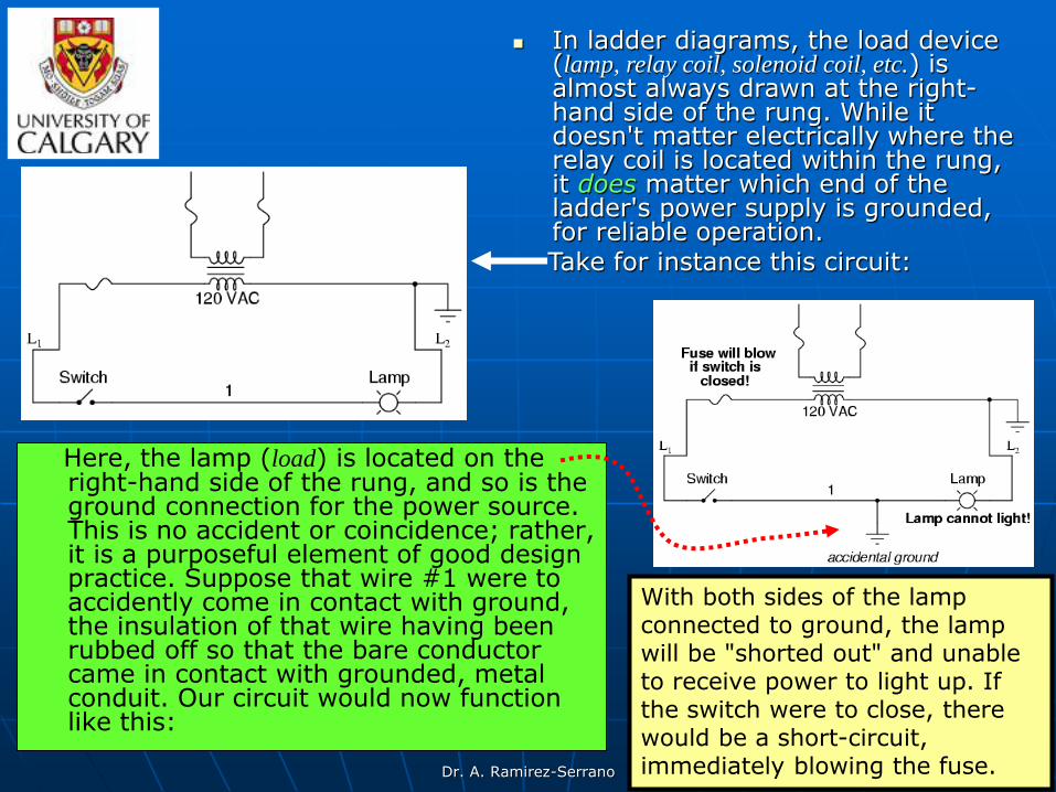
Here, the lamp (load) is located on the right-hand side of the rung, and so is the ground connection for the power source. This is no accident or coincidence; rather, it is a purposeful element of good design practice. Suppose that wire #1 were to accidently come in contact with ground, the insulation of that wire having been rubbed off so that the bare conductor came in contact with grounded, metal conduit. Our circuit would now function like this:
In ladder diagrams, the load device (lamp, relay coil, solenoid coil, etc.) is almost always drawn at the right-hand side of the rung. While it doesn't matter electrically where the relay coil is located within the rung, it does matter which end of the ladder's power supply is grounded, for reliable operation.
Take for instance this circuit:
With both sides of the lamp connected to ground, the lamp will be "shorted out" and unable to receive power to light up. If the switch were to close, there would be a short-circuit, immediately blowing the fuse.

Dr. A. Ramirez-Serrano
However, consider what would happen to the circuit with the same fault (wire #1 coming in contact with ground), except this time we'll swap the positions of switch and fuse (L2 is still grounded):
This time the accidental grounding of wire #1 will force power to the lamp while the switch will have no effect. It is much safer to have a system that blows a fuse in the event of a ground fault than to have a system that uncontrollably energizes lamps, relays, or solenoids in the event of the same fault. For this reason, the load(s) must always be located nearest the grounded power conductor in the ladder diagram.

Dr. A. Ramirez-Serrano
Digital logic functions in
“ladder logic”
We can construct simply logic functions for our hypothetical lamp circuit, using multiple contacts, and document these circuits quite easily and understandably with additional rungs to our original "ladder."

Dr. A. Ramirez-Serrano
“OR” functions in ladder logic
If we use standard binary notation for the status of the switches and lamp (0 for unactuated or de-energized; 1 for actuated or energized), a truth table can be made to show how the logic works:
Now, the lamp will come on if either contact A or contact B is actuated, because all it takes for the lamp to be energized is to have at least one path for current from wire L1 to wire 1. What we have is a simple OR logic function, implemented with nothing more than contacts and a lamp.
Dr. A. Ramirez-Serrano
“AND” functions in ladder
logic
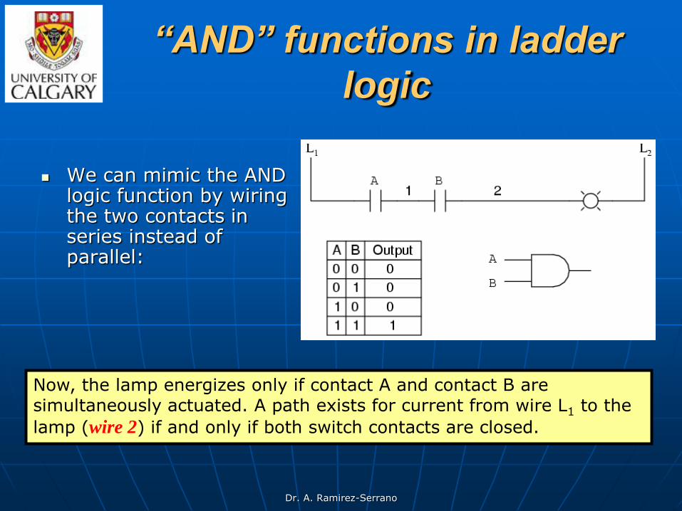
We can mimic the AND logic function by wiring the two contacts in series instead of parallel:
Now, the lamp energizes only if contact A and contact B are simultaneously actuated. A path exists for current from wire L1 to the
lamp (wire 2) if and only if both switch contacts are closed.

Dr. A. Ramirez-Serrano
“NOT” function in ladder
logic
The logical inversion, or NOT, function can be performed on a contact input simply by using a normally-closed contact instead of a normally-open contact:
Now, the lamp energizes if the contact is not actuated, and de-energizes when the contact is actuated.
Dr. A. Ramirez-Serrano
“NAND” function in ladder
logic
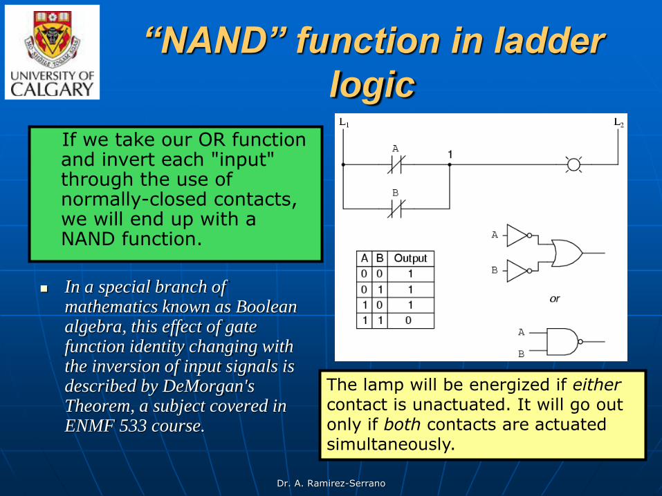
In a special branch of mathematics known as Boolean algebra, this effect of gate function identity changing with the inversion of input signals is described by DeMorgan's Theorem, a subject covered in ENMF 533 course.
If we take our OR function and invert each "input" through the use of normally-closed contacts, we will end up with a NAND function.
The lamp will be energized if either contact is unactuated. It will go out only if both contacts are actuated simultaneously.

Dr. A. Ramirez-Serrano
“NOR” function in ladder
logic
Likewise, if we take our AND function and invert each "input" through the use of normally-closed contacts, we will end up with a NOR function:
A pattern quickly reveals itself when ladder circuits are compared with their logic gate counterparts:
1. Parallel contacts are equivalent to an OR gate.
2. Series contacts are equivalent to an AND gate.
3. Normally-closed contacts are equivalent to a NOT gate (inverter).
Dr. A. Ramirez-Serrano
Combinatorial circuits
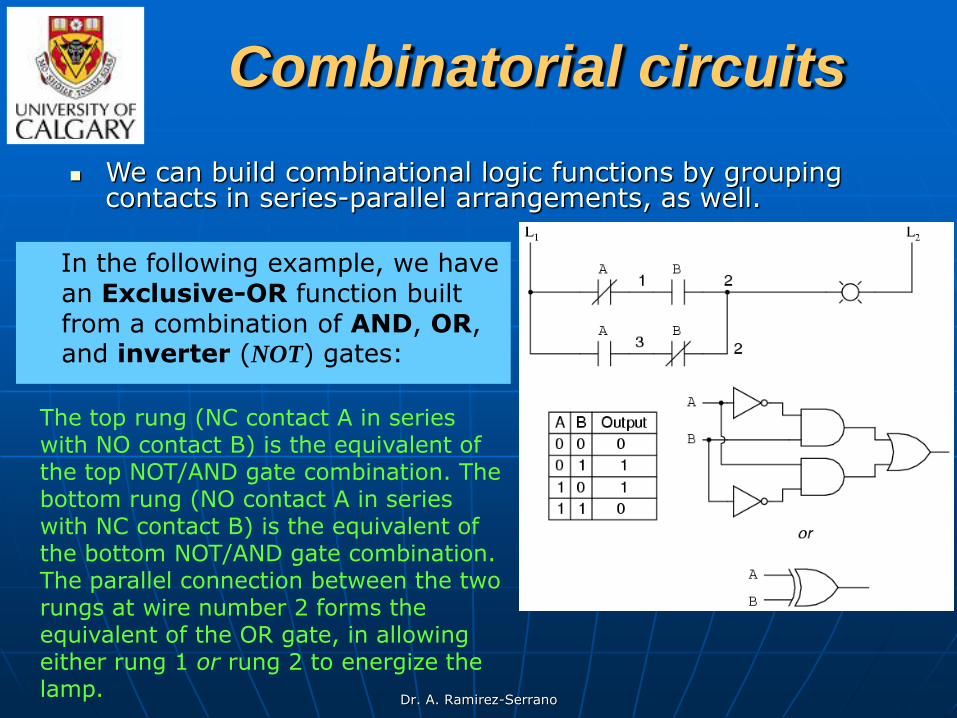
In the following example, we have an Exclusive-OR function built from a combination of AND, OR, and inverter (NOT) gates:
We can build combinational logic functions by grouping contacts in series-parallel arrangements, as well.
The top rung (NC contact A in series with NO contact B) is the equivalent of the top NOT/AND gate combination. The bottom rung (NO contact A in series with NC contact B) is the equivalent of the bottom NOT/AND gate combination. The parallel connection between the two rungs at wire number 2 forms the equivalent of the OR gate, in allowing either rung 1 or rung 2 to energize the lamp.

Dr. A. Ramirez-Serrano
To make the Exclusive-OR function, we had to use two contacts per input: one for direct input and the other for "inverted" input. The two "A" contacts are physically actuated by the same mechanism, as are the two "B" contacts. The common association between contacts is denoted by the label of the contact. There is no limit to how many contacts per switch can be represented in a ladder diagram, as each new contact on any switch or relay (either normally-open or normally-closed) used in the diagram is simply marked with the same label.
Sometimes, multiple contacts on a single switch (or relay) are designated by a compound labels, such as "A-1" and "A-2" instead of two "A" labels. This may be especially useful if you want to specifically designate which set of contacts on each switch or relay is being used for which part of a circuit. For simplicity's sake, I'll refrain from such elaborate labeling in this lesson. If you see a common label for multiple contacts, you know those contacts are all actuated by the same mechanism.

Dr. A. Ramirez-Serrano
Another way to invert the
outputs of a switch If we wish to invert the
output of any switch-generated logic function, we must use a relay with a normally-closed contact. For instance, if we want to energize a load based on the inverse, or NOT, of a normally-open contact, we could do this:
We will call the relay, "control relay 1," or CR1. When the coil of CR1 (symbolized with the pair of parentheses on the first rung) is energized, the contact on the second rung opens, thus de-energizing the lamp. From switch A to the coil of CR1, the logic function is noninverted. The normally-closed contact actuated by relay coil CR1 provides a logical inverter function to drive the lamp opposite that of the switch's actuation status.

Dr. A. Ramirez-Serrano
Applying this inversion strategy to one of our inverted-input functions created earlier, such as the OR-to-NAND, we can invert the output with a relay to create a
noninverted function:
From the switches to the coil of CR1, the logical function is that of a NAND gate. CR1's normally-closed contact provides one final inversion to turn the NAND function into an AND function.

Dr. A. Ramirez-Serrano
Permissive and interlock
circuits A practical application of switch and relay logic is in control
systems where several process conditions have to be met before a piece of equipment is allowed to start.
A good example of this is burner control for large combustion furnaces. In order for the burners in a large furnace to be started
safely, the control system requests "permission" from several
process switches, including high and low fuel pressure, air fan flow check, exhaust stack damper position, access door position, etc.
Each process condition is called a permissive, and each permissive switch contact is wired in series, so that if any one of them detects an unsafe condition, the circuit will be opened:

Dr. A. Ramirez-Serrano
Another practical application of relay logic is in control systems where we want to ensure two incompatible events cannot occur at the same time.
When contactor M1 is energized, the 3 phases (A, B, and C) are connected directly to terminals 1, 2, and 3 of the motor, respectively.
An example of this is in reversible motor control, where two motor contactors are wired to switch polarity (or phase sequence) to an electric motor, and we don't want the forward and reverse contactors energized simultaneously:
However, when contactor M2 is energized, phases A and B are reversed, A going to motor terminal 2 and B going to motor terminal 1. This reversal of phase wires results in the motor spinning the opposite direction. Let's examine the control circuit for these two contactors:
Interlock circuits
Thermal overload contact

Dr. A. Ramirez-Serrano
Take note of the normally-closed "OL" contact, which is the thermal overload contact activated by the "heater" elements wired in series with each phase of the AC motor. If the heaters get too hot, the contact will change from its normal (closed) state to being open, which will prevent either contactor from energizing.
This control system will work fine, so long as no one pushes both buttons at the same time. If someone were to do that, phases A and B would be short-circuited together by virtue of the fact that contactor M1 sends phases A and B straight to the motor and contactor M2 reverses them; phase A would be shorted to phase B and visa-versa. Obviously, this is a bad control system design!
Thermal overload contact

Dr. A. Ramirez-Serrano
This is called interlocking, and it is accomplished through the use of auxiliary contacts on each contactor, as such:
Now, when M1 is energized, the normally-closed auxiliary contact on the second rung will be open, thus preventing M2 from being energized, even if the "Reverse" pushbutton is actuated. Likewise, M1's energization is prevented when M2 is energized. Note, as well, how additional wire numbers (4 and 5) were added to reflect the wiring changes. It should be noted that this is not the only way to interlock contactors to prevent a short-circuit condition. Some contactors come equipped with the option of a mechanical interlock: a lever joining the armatures of two contactors together so that they are physically prevented from simultaneous closure. For additional safety, electrical interlocks may still be used, and due to the simplicity of the circuit there is no good reason not to employ them in addition to mechanical interlocks.
To prevent this occurrence from happening, we can design the circuit so that the energization of one contactor prevents the energization of the other.

Dr. A. Ramirez-Serrano
Thank you!
Next class: Motor control circuits
Time: 11:00 a.m.
Place: ME 322

Dr. A. Ramirez-Serrano
Motor control circuits The interlock contacts installed in the previous section's motor control
circuit work fine, but the motor will run only as long as each pushbutton switch is held down.
If we wanted to keep the motor running even after the operator takes his or her hand off the control switch(es), we could change the circuit in a couple of different ways: we could replace the pushbutton switches with toggle switches, or we could add some more relay logic to "latch" the control circuit with a single, momentary
actuation of either switch (See fig. below for an implementation of this commonly used in
industry approach):
When the "Forward" pushbutton is actuated, M1
will energize, closing the normally-open auxiliary contact in parallel with that switch. When the pushbutton is released, the closed M1 auxiliary contact will maintain current to the coil of M1, thus
latching the " Forward " circuit in the "on" state.
The same sort of thing will happen when the
"Reverse" pushbutton is pressed. These parallel
auxiliary contacts are sometimes referred to as seal-in contacts, the word "seal" meaning essentially the same thing as the word latch.

Dr. A. Ramirez-Serrano
Stop Motors! The previous circuit creates a new problem: how to stop the motor! In the previous circuit the motor will run either forward or backward once the corresponding pushbutton switch is pressed, and will continue to run as long as there is power. To stop either circuit (forward or backward), we require some means for the operator to interrupt power to the motor contactors. We'll call this new switch, Stop (normally closed):
Now, if either forward or reverse circuits are latched, they may be
"unlatched" by momentarily pressing the "Stop" pushbutton, which will
open either forward or reverse circuit, de-energizing the energized
contactor, and returning the seal-in contact to its normal (open) state.
The "Stop" switch, having normally-closed contacts, will conduct power to either forward or reverse circuits when released.

Dr. A. Ramirez-Serrano
Another Practical Aspect of
Motor Control
So far, so good. Let's consider another practical aspect of our motor control scheme before we quit adding to it.
If our hypothetical motor turned a mechanical load with a lot of momentum, such as a large air fan, the motor might continue to coast for a substantial amount of time after the stop button had been pressed. This could be problematic if an operator were to try to reverse the motor direction without waiting for the fan to stop turning. If the fan was still coasting forward and the "Reverse" pushbutton was pressed, the motor would struggle to overcome that inertia of the large fan as it tried to begin turning in reverse, drawing excessive current and potentially reducing the life of the motor, drive mechanisms, and fan. What we might like to have is some kind of a time-delay function in this motor control system to prevent such a premature startup from happening.

Dr. A. Ramirez-Serrano
Let's begin by adding a couple of time-delay relay coils, one in parallel with each motor contactor coil. If we use contacts that delay returning to their normal state, these relays will provide us a "memory" of which direction the motor was last powered to turn.
What we want each time-delay contact to do is to open the starting-switch leg of the opposite rotation circuit for several seconds, while the fan coasts to a halt.
If the motor has been running in the forward direction, both M1 and TD1 will
have been energized. This being the case, the normally-closed, timed-closed
contact of TD1 between wires 8 and 5 will have immediately opened the moment TD1 was energized. When the stop button is pressed, contact TD1 waits for the specified amount of time before returning to its normally-closed state, thus holding the reverse pushbutton circuit open for the duration so M2 can't be energized. When TD1 times out, the contact will close and the circuit will allow M2 to be energized, if the reverse pushbutton is pressed. In like manner, TD2 will prevent the "Forward" pushbutton from energizing M1 until the prescribed time
delay after M2 (and TD2) have been de-energized.

Dr. A. Ramirez-Serrano
The careful observer will notice that the time-interlocking functions of TD1 and TD2 render the M1 and M2 interlocking contacts redundant.
We can get rid of auxiliary contacts M1 and M2 for interlocks and just use TD1 and TD2's contacts, since they immediately open when their respective relay coils are energized, thus "locking out" one contactor if the other is energized.
Each time delay relay will serve a dual purpose: i) preventing the other contactor from energizing while the motor is running, and ii) preventing the same contactor from energizing until a prescribed time after motor shutdown. The resulting circuit has the advantage of being simpler than the previous example.

Dr. A. Ramirez-Serrano
Fail-safe design
Logic circuits, whether comprised of electromechanical relays or solid-state gates, can be built in many different ways to perform the same functions. There is
usually no one "correct" way to design a complex logic
circuit, but there are usually ways that are better than others.
In control systems, safety is (or at least should be) an important design priority.
If there are multiple ways in which a digital control circuit can be designed to perform a task, and one of those ways happens to hold certain advantages in safety over the others, then that design is the better one to choose.

Dr. A. Ramirez-Serrano
Let's take a look at a simple system
and consider how it might be
implemented in relay logic Suppose that a large laboratory
or industrial building is to be equipped with a fire alarm system, activated by any one of several latching switches installed throughout the facility. The system should work so that the alarm siren will energize if any one of the switches is actuated. At first glance it seems as though the relay logic should be incredibly simple: just use normally-open switch contacts and connect them all in parallel with each other.
Essentially, this is the OR logic function implemented with four switch inputs. We could expand this circuit to include any number of switch inputs, each new switch being added to the parallel network, but we'll limit it to 4 in this example to keep things simple. At any rate, it is an elementary system and there seems to be little possibility of trouble. Except in the event of a wiring failure, that is.
Fire alarm system
Dr. A. Ramirez-Serrano
Potential circuit
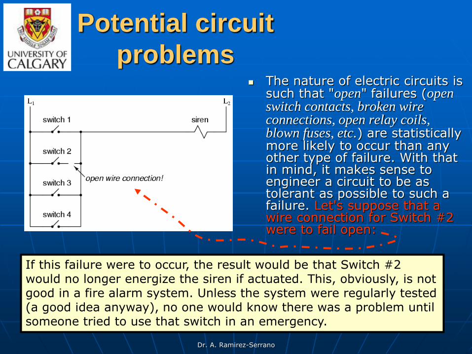
problems The nature of electric circuits is
such that "open" failures (open switch contacts, broken wire connections, open relay coils, blown fuses, etc.) are statistically more likely to occur than any other type of failure. With that in mind, it makes sense to engineer a circuit to be as tolerant as possible to such a failure. Let's suppose that a wire connection for Switch #2 were to fail open:
If this failure were to occur, the result would be that Switch #2 would no longer energize the siren if actuated. This, obviously, is not good in a fire alarm system. Unless the system were regularly tested (a good idea anyway), no one would know there was a problem until someone tried to use that switch in an emergency.
Dr. A. Ramirez-Serrano
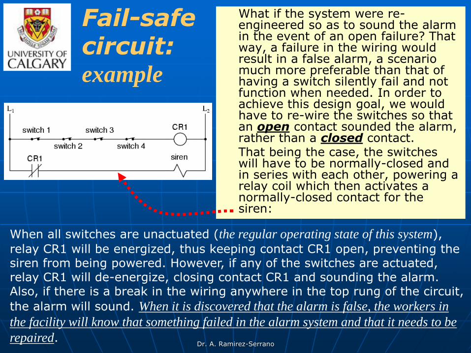
What if the system were re-engineered so as to sound the alarm in the event of an open failure? That way, a failure in the wiring would result in a false alarm, a scenario much more preferable than that of having a switch silently fail and not function when needed. In order to achieve this design goal, we would have to re-wire the switches so that an open contact sounded the alarm, rather than a closed contact.
That being the case, the switches will have to be normally-closed and in series with each other, powering a relay coil which then activates a normally-closed contact for the siren:
When all switches are unactuated (the regular operating state of this system),
relay CR1 will be energized, thus keeping contact CR1 open, preventing the siren from being powered. However, if any of the switches are actuated, relay CR1 will de-energize, closing contact CR1 and sounding the alarm. Also, if there is a break in the wiring anywhere in the top rung of the circuit,
the alarm will sound. When it is discovered that the alarm is false, the workers in
the facility will know that something failed in the alarm system and that it needs to be
repaired.
Fail-safe circuit: example
Dr. A. Ramirez-Serrano
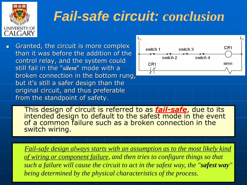
Fail-safe circuit: conclusion
Granted, the circuit is more complex than it was before the addition of the control relay, and the system could still fail in the "silent" mode with a
broken connection in the bottom rung, but it's still a safer design than the original circuit, and thus preferable from the standpoint of safety.
This design of circuit is referred to as fail-safe, due to its intended design to default to the safest mode in the event of a common failure such as a broken connection in the switch wiring.
Fail-safe design always starts with an assumption as to the most likely kind
of wiring or component failure, and then tries to configure things so that
such a failure will cause the circuit to act in the safest way, the "safest way"
being determined by the physical characteristics of the process.

Dr. A. Ramirez-Serrano
Take for example an electrically-actuated (solenoid) valve for turning on cooling water to a machine. Energizing the solenoid coil will move an armature which then either opens or closes the valve mechanism, depending on what kind of valve we specify. A spring will return the valve to its "normal" position when the solenoid is de-energized. We already know that an open failure in the wiring or solenoid coil is more likely than a short or any other type of failure, so we should design this system to be in its safest mode with the solenoid de-energized.
If it's cooling water we're controlling with this valve, chances are it is safer to have the cooling water turn on in the event of a failure than to shut off, the consequences of a machine running without coolant usually being severe. This means we should specify a valve that turns on (opens up) when de-energized and turns off (closes down) when energized. This may seem "backwards" to have the valve set up this way, but it will make for a safer system in the end.
One interesting application of fail-safe design is in the power generation and distribution industry, where large circuit breakers need to be opened and closed by electrical control signals from protective relays. If a 50/51 relay (instantaneous and time overcurrent) is going to command a circuit breaker to trip (open) in the event of excessive current, should we design it so that the relay closes a switch contact to send a "trip" signal to the breaker, or opens a switch contact to interrupt a regularly "on" signal to initiate a breaker trip? We know that an open connection will be the most likely to occur, but what is the safest state of the system: breaker open or breaker closed?
At first, it would seem that it would be safer to have a large circuit breaker trip (open up and shut off power) in the event of an open fault in the protective relay control circuit, just like we had the fire alarm system default to an alarm state with any switch or wiring failure. However, things are not so simple in the world of high power. To have a large circuit breaker indiscriminately trip open is no small matter, especially when customers are depending on the continued supply of electric power to supply hospitals, telecommunications systems, water treatment systems, and other important infrastructures. For this reason, power system engineers have generally agreed to design protective relay circuits to output a closed contact signal (power applied) to open large circuit breakers, meaning that any open failure in the control wiring will go unnoticed, simply leaving the breaker in the status quo position.
Is this an ideal situation? Of course not. If a protective relay detects an overcurrent condition while the> Transfer interrupted! ll not be able to trip open the circuit breaker. Like the first fire alarm system design, the "silent" failure will be evident
only when the system is needed. However, to engineer the control circuitry the other way -- so that any open failure would immediately shut the circuit breaker off, potentially blacking out large potions of the power grid -- really isn't a better alternative.
An entire book could be written on the principles and practices of good fail-safe system design. At least here, you know a couple of the fundamentals: that wiring tends to fail open more often than shorted, and that an electrical control system's (open) failure mode should be such that it indicates and/or actuates the real-life process in the safest alternative mode. These fundamental principles extend to non-electrical systems as well: identify the most common mode of failure, then engineer the system so that the probable failure mode places the system in the safest condition.

Dr. A. Ramirez-Serrano
Thank you!
Next class: PLC Hardware
Time: 11:00 a.m.
Place: ME 322
Dr. A. Ramirez-Serrano
Computer-Based Control for
Manufacturing ( ENMF 515 )
Instructor: Dr. Alejandro Ramirez-Serrano
Office: ME420 Phone: 220-3632
E-mail: [email protected]
More about: . “PLC Hardware”
Allen-Bradley
PLC-5

Dr. A. Ramirez-Serrano
Main Parts of a PLC
Many PLC configurations are available, even from a single vendor. But, in each of these there are common components and concepts. The most essential components are:
Power Supply - This can be built into the PLC or be an
external unit. Common voltage levels required by the PLC
(with and without the power supply) are 24Vdc, 120Vac,
220Vac.
CPU (Central Processing Unit) - This is a computer where
ladder logic is stored and processed.
I/O (Input/Output) - A number of input/output terminals must
be provided so that the PLC can monitor the process and
initiate actions.
Indicator lights - These indicate the status of the PLC
including power on, program running, and a fault. These are
essential when diagnosing problems.

Dr. A. Ramirez-Serrano
PLC forms or configuration
The configuration of the PLC refers to the packaging of the components. Typical configurations are listed below from largest to smallest:
Rack - A rack is often large (up to 18” by 30” by 10”) and can hold multiple
cards. When necessary, multiple racks can be connected together. These tend to be
the highest cost, but also the most flexible and easy to maintain.
Mini - These are similar in function to PLC racks, but about half the size.
Shoebox - A compact, all-in-one unit (about the size of a shoebox) that has
limited expansion capabilities. Lower cost, and compactness make these ideal for
small applications.
Micro - These units can be as small as a deck of cards. They tend to have fixed
quantities of I/O and limited abilities, but costs will be the lowest.
Software - A software based PLC requires a computer with an interface card,
but allows the PLC to be connected to sensors and other PLCs across a network.

Dr. A. Ramirez-Serrano
A PLC has many "input" terminals, through which it interprets
"high" and "low" logical states from sensors and switches.
It also has many output terminals, through which it outputs
"high" and "low" signals to power lights, solenoids, contactors,
small motors, and other devices lending themselves to on/off control.
In an effort to make PLCs easy to program, their programming language was designed to resemble ladder logic diagrams. Thus, an industrial electrician or electrical engineer accustomed to reading ladder logic schematics would feel comfortable programming a PLC to perform the same control functions.
PLC inputs & outputs
Dr. A. Ramirez-Serrano
PLC inputs & outputs
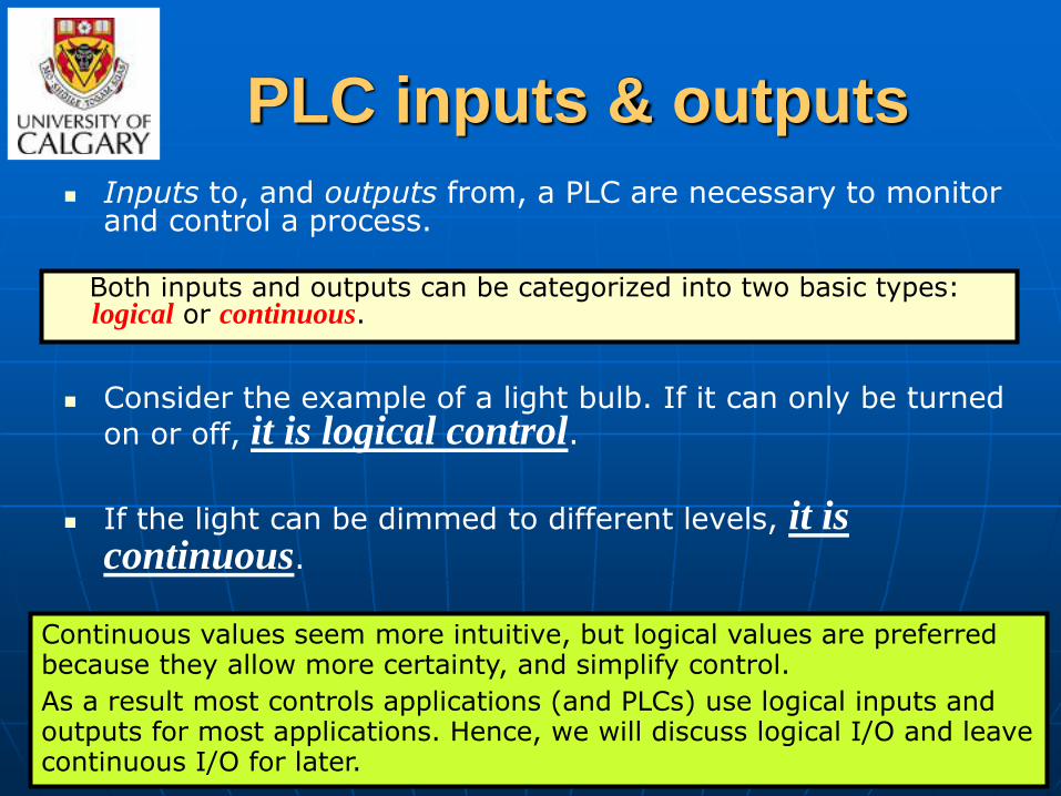
Inputs to, and outputs from, a PLC are necessary to monitor and control a process.
Consider the example of a light bulb. If it can only be turned
on or off, it is logical control.
If the light can be dimmed to different levels, it is continuous.
Both inputs and outputs can be categorized into two basic types: logical or continuous.
Continuous values seem more intuitive, but logical values are preferred because they allow more certainty, and simplify control.
As a result most controls applications (and PLCs) use logical inputs and outputs for most applications. Hence, we will discuss logical I/O and leave continuous I/O for later.

Dr. A. Ramirez-Serrano
Input Types
Proximity Switches
Switches
Potentiometer
LVDTs
Voltages
12-24 Vdc
100-120 Vac
10-60 Vdc
12-24 Vac/dc
5 Vdc (TTL)
200-240 Vac
48 Vdc
24 Vac
PLC input types
Inputs come from sensors that translate physical phenomena into electrical signals. Typical examples of sensors are listed below in relative order of popularity.
Switches - mechanical mechanisms will open or close electrical contacts for a logical signal.
Potentiometer - measures angular positions continuously, using resistance.
LVDT (linear variable differential transformer) - measures linear displacement continuously
using magnetic coupling.
Proximity Switches - use inductance,
capacitance or light to detect an object logically.
Dr. A. Ramirez-Serrano
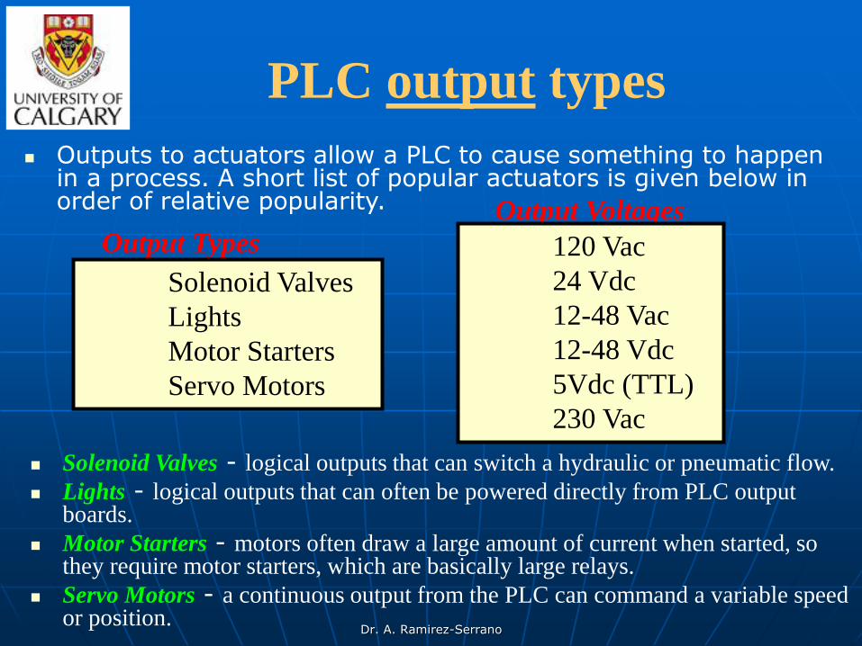
Output Types
Solenoid Valves
Lights
Motor Starters
Servo Motors
Output Voltages
120 Vac
24 Vdc
12-48 Vac
12-48 Vdc
5Vdc (TTL)
230 Vac
PLC output types
Solenoid Valves - logical outputs that can switch a hydraulic or pneumatic flow.
Lights - logical outputs that can often be powered directly from PLC output boards.
Motor Starters - motors often draw a large amount of current when started, so they require motor starters, which are basically large relays.
Servo Motors - a continuous output from the PLC can command a variable speed or position.
Outputs to actuators allow a PLC to cause something to happen in a process. A short list of popular actuators is given below in order of relative popularity.

Dr. A. Ramirez-Serrano
More about PLC outputs
Outputs from PLCs are often relays, but they can also be solid state electronics such as transistors for DC outputs or Triacs for AC outputs.
Continuous outputs require special output cards with digital to analog converters.

Dr. A. Ramirez-Serrano
More about PLC inputs &
outputs Inputs for a PLC come in a few basic varieties, the simplest
are AC and DC inputs.
Sourcing and sinking inputs are also popular. This output method dictates that a device does not supply any power. Instead, the device only switches current on or off, like a simple switch.
Sinking - When active the output allows current to flow to a common
ground. This is best selected when different voltages are supplied.
Sourcing - When active, current flows from a supply, through the
output device and to ground. This method is best used when all devices use a single supply voltage.
This is also referred to as NPN (sinking) and PNP (sourcing). PNP is more popular. This will be covered in more detail in the section about sensors.

Dr. A. Ramirez-Serrano
Signal connection and programming standards vary somewhat between different models of PLC, but they are similar enough to allow a "generic" introduction to PLC programming.
The figure on the right shows a simple PLC, as it might appear from a front view.
Two screw terminals provide connection to 120 volts
AC for powering the PLC's internal circuitry,
labeled L1 and L2.
Six screw terminals on the left-hand side provide
connection to input devices, each terminal
representing a different input "channel" with its
own "X" label. The lower-left screw terminal is a
"Common" connection, which is generally
connected to L2 (neutral) of the 120 VAC power
source.
Power supply
Ou
tpu
ts
Inpu
ts

Dr. A. Ramirez-Serrano
Inside the PLC housing, connected between each input terminal and the Common terminal, is an opto-isolator device (Light-Emitting Diode) that provides an electrically isolated "high" logic signal to the computer's circuitry (a photo-transistor interprets the LED's light) when there is 120 VAC power applied between the respective input terminal and the Common terminal.
An indicating LED on the front panel of the PLC gives visual indication of an "energized" input:

Dr. A. Ramirez-Serrano
INPUTS
In smaller PLCs the inputs are normally built in and are specified when purchasing the PLC.
For larger PLCs the inputs are purchased as modules, or cards, with 8 or 16 inputs of the same type on each card.
For discussion purposes we will discuss all inputs as if they have been purchased as cards. The list below shows typical ranges for input voltages, and is roughly in order of popularity.
12-24 Vdc ; 100-120 Vac ; 10-60 Vdc
12-24 Vac/dc ; 5 Vdc (TTL) ; 200-240 Vac
48 Vdc ; 24 Vac
Most popular Least popular

Dr. A. Ramirez-Serrano
24 V ACPowerSupply
normally open push-button
normally opentemperature switch
PLC Input Card24V AC
it is in rack 1I/O Group 3
00
01
02
03
04
05
06
07
I:013
01
I:013
03
Push Button
Temperature Sensor
COM
Note: inputs are normally high impedance. This means that they will
use very little current.
Hot
Neut.
Fig. 3.2 - Input Card Example
PLC input cards rarely supply power, this means that an external power supply is needed to supply power for the inputs and sensors. The example in Figure 3.2 shows how to connect an AC input card.
Inputs:
PLC Cards
Also called “slot”

Dr. A. Ramirez-Serrano
Circuits
Many beginners become confused about where connections are needed in the circuit above.
The key word to remember is circuit, which means that there is a full loop that the voltage must be able to follow.
In Figure 3.2 we can start following the circuit (loop) at the power supply. The path goes through the switches, through the input card, and back to the power supply where it flows back through to the start. In a full PLC implementation there will be many circuits that must each be complete.

Dr. A. Ramirez-Serrano
Example:
I:012
02
I:025
03
O:028
04
…
… I/O: Rack, Slot
I:025
03
O:028
04
120 Vac
5 Vdc
02
5 Vdc I:012
Slot No. 5 Slot No. 8
Input 01
Rack No. 2
Input 01
Input 02
Slot No. 8 Slot No. 2
Input n
Slot No. 2 Slot No. 3
Input n
Rack No. 1 Input 02

Dr. A. Ramirez-Serrano
Common vs. Ground A second important concept is the common.
Here the neutral on the power supply is the common, or reference
voltage.
In effect we have chosen this to be our 0V reference, and all other voltages are measured relative to it. If we had a second power supply, we would also need to connect the neutral so that both neutrals would be connected to the same common.
Often common and ground will be confused. The common is a reference, or datum voltage that is used for 0V, but the ground is used to prevent shocks and damage to equipment. The ground is connected under a building to a metal pipe or grid in the ground. This is connected to the electrical system of a building, to the power outlets, where the metal cases of electrical equipment are connected. When power flows through the ground it is bad. Unfortunately many engineers, and manufacturers mix up ground and common. It is very common to find a power supply with the ground and common mislabeled.

Dr. A. Ramirez-Serrano
Isolated I/O cards
One final concept that tends to trap beginners is that each input card is isolated.
This means that if you have connected a common to only one card, then the other cards are not connected. When this happens the other cards will not work properly. You must connect a common for each of the output cards.

Dr. A. Ramirez-Serrano
Input Cards: Selection
There are many trade-offs when deciding which type of input cards to use.
• DC voltages are usually lower, and therefore safer (i.e., 12-24V).
• DC inputs are very fast, AC inputs require a longer on-time. For example, a 60Hz wave may require up to 1/60sec for reasonable recognition.
• DC voltages can be connected to larger variety of electrical systems.
• AC signals are more immune to noise than DC, so they are suited to long distances, and noisy (magnetic) environments.
• AC power is easier and less expensive to supply to equipment.
• AC signals are very common in many existing automation devices.

Dr. A. Ramirez-Serrano
OUTPUTS
As with input modules, output modules rarely supply any power, but instead act as switches. External power supplies are connected to the output card and the card will switch the power on or off for each output. Typical output voltages are listed below, and roughly ordered by popularity.
120 Vac ; 24 Vdc ; 12-48 Vac
12-48 Vdc ; 5 Vdc (TTL) ; 230 Vac
Most popular Least popular
Dr. A. Ramirez-Serrano
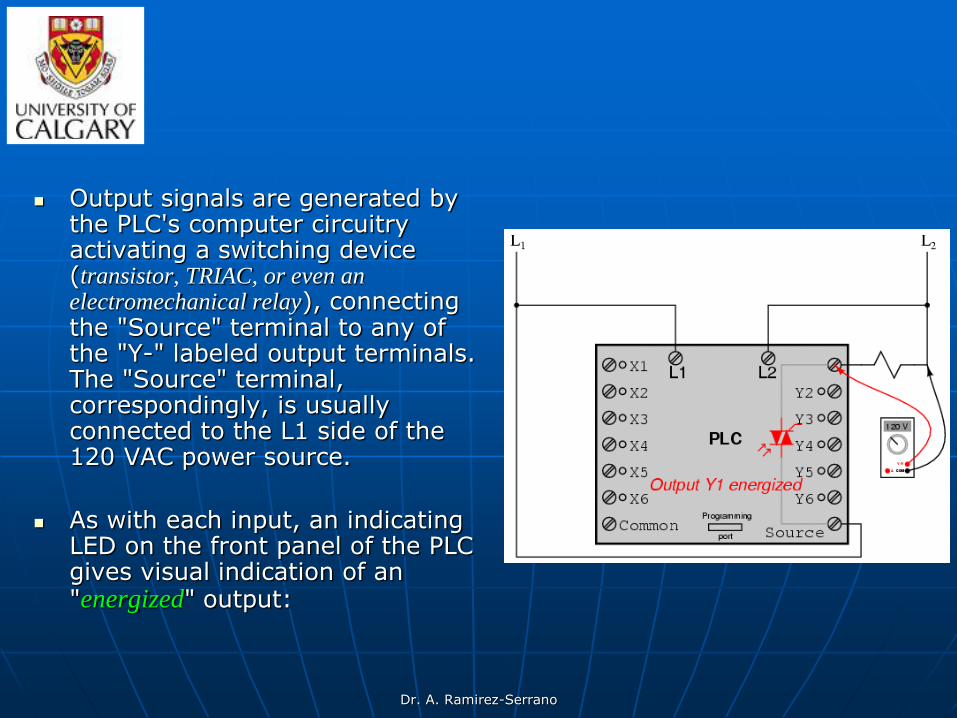
Output signals are generated by the PLC's computer circuitry activating a switching device (transistor, TRIAC, or even an electromechanical relay), connecting the "Source" terminal to any of the "Y-" labeled output terminals. The "Source" terminal, correspondingly, is usually connected to the L1 side of the 120 VAC power source.
As with each input, an indicating LED on the front panel of the PLC gives visual indication of an "energized" output:

Dr. A. Ramirez-Serrano
Output Cards
Output cards typically have 8 to 16 outputs of the same type and can be purchased with different current ratings.
A common choice when purchasing output cards is relays,
transistors or triacs.
Relays are the most flexible output devices. They are capable of switching both AC and DC outputs. But, they are slower (about 10ms switching is typical), they are bulkier, they cost more, and they will wear out after millions of cycles. Relay outputs are often called dry contacts.
Transistors are limited to DC outputs, and Triacs are limited to AC outputs. Transistor and triac outputs are called switched outputs.
Dr. A. Ramirez-Serrano
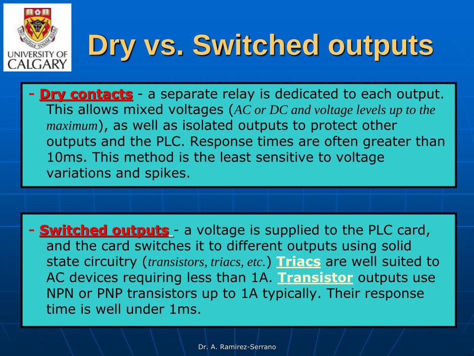
Dry vs. Switched outputs
- Dry contacts - a separate relay is dedicated to each output. This allows mixed voltages (AC or DC and voltage levels up to the
maximum), as well as isolated outputs to protect other
outputs and the PLC. Response times are often greater than 10ms. This method is the least sensitive to voltage variations and spikes.
- Switched outputs - a voltage is supplied to the PLC card, and the card switches it to different outputs using solid state circuitry (transistors, triacs, etc.) Triacs are well suited to AC devices requiring less than 1A. Transistor outputs use NPN or PNP transistors up to 1A typically. Their response time is well under 1ms.
Dr. A. Ramirez-Serrano
Output Card
Example
(Transistors) 24 V DCOutput Card
in rack 01I/O group 2
COM
00
01
02
03
04
05
06
07
24 V Lamp
Relay
+24 V DCPower
120 V AC
Power
Motor
Supply
Supply
O:012
03
O:012
07
Motor
Lamp
Neut.
COM
Outputs:
PLC Cards
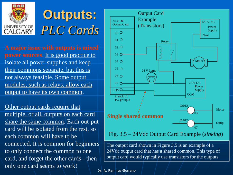
Fig. 3.5 – 24Vdc Output Card Example (sinking)
A major issue with outputs is mixed
power sources. It is good practice to
isolate all power supplies and keep
their commons separate, but this is
not always feasible. Some output
modules, such as relays, allow each
output to have its own common.
Other output cards require that
multiple, or all, outputs on each card
share the same common. Each out-put
card will be isolated from the rest, so
each common will have to be
connected. It is common for beginners
to only connect the common to one
card, and forget the other cards - then
only one card seems to work!
The output card shown in Figure 3.5 is an example of a
24Vdc output card that has a shared common. This type of
output card would typically use transistors for the outputs.
Single shared common

Dr. A. Ramirez-Serrano
24 V DCOutput Card
in rack 01I/O group 2
V+
00
01
02
03
04
05
06
07
24 V lamp
Relay
+24 V DC
Power
120 V AC
Power
Motor
Supply
Supply
O:012
03
O:012
07
Motor
Lamp
Neut.
COM
Output Card
Example
(Transistors)
Fig. 3.6 – 24Vdc Output Card Example with a voltage
input (sourcing)
The circuits in Fig. 3.6 had the
sequence of power supply, then device,
then PLC card, then power supply. This
requires that the output card have a
common. Some output schemes reverse
the device and PLC card, thereby
replacing the common with a voltage
input. The example in Fig. 3.5
(previous slide) is repeated in Fig. 3.6
for a voltage supply card.
Voltage supply
cards
In this example the +ive terminal of the
24Vdc supply is connected to the output
card directly. When an output is ON
power will be supplied to that output.
E.g., if output 07 is ON then the supply
voltage will be output to the lamp.
Current will flow through the lamp and
back to the common on the power
supply. The operation is very similar for
the relay switching the motor. Notice that
the ladder logic is identical to that in Fig.
3.5. With this type of output card only
one power supply can be used.

Dr. A. Ramirez-Serrano
120 V AC/DCOutput Card
in rack 01I/O group 2
00
01
02
03
04
05
06
07
24 V lamp
Relay
24 V DCPower
120 V ACPower
Motor
Supply
Supply
O:012
03
O:012
07
Motor
LampFig. 3.7 - Relay output
card example.
PLC cards
with relay
outputs
We can also use relay outputs to switch the
outputs. The example shown in Fig. 3.5 and
Fig. 3.6 is repeated yet again in Fig. 3.7 for
relay output.
In this example the 24Vdc supply is
connected directly to both relays (note that
this requires 2 connections now, whereas
the previous example only required one.)
When an output is activated the output
switches ON and power is delivered to the
output devices.
This layout is more similar to Fig. 3.6 with
the outputs supplying voltage, but the
relays could also be used to connect outputs
to grounds, as in Fig. 3.5. When using relay
outputs it is possible to have each output
isolated from the next. A relay output card
could have AC and DC outputs beside each
other.
Dr. A. Ramirez-Serrano
Some Design Issues:
Things to consider
• DC voltages are usually lower, and therefore safer (e.g., 24V).
• DC inputs are very fast, AC inputs require a longer on-time.
• DC voltages can be connected to more electrical systems.
• AC signals are more immune to noise than DC.
• AC power is easier and less expensive to supply to equipment.
• AC signals are very common.
Dr. A. Ramirez-Serrano
Relays: some terminology
Contactor - Special relays for switching large current loads.
Motor Starter - Basically a contactor in series with an overload relay
to cut off when too much current is drawn.
Arc Suppression - when any relay is opened or closed an arc will
jump. This becomes a major problem with large relays. On relays
switching AC this problem can be overcome by opening the relay when
the voltage goes to zero (while crossing between negative and positive).
When switching DC loads this problem can be minimized by blowing
pressurized gas across during opening to suppress the arc formation.
AC coils - If a normal relay coil is driven by AC power the contacts
will vibrate open and close at the frequency of the AC power. This
problem is overcome by adding a shading pole to the relay.
Although relays are rarely used for control logic, they are still essential
for switching large power loads. Some important terminology for relays
is given below.

Dr. A. Ramirez-Serrano
Selecting PLC relays
If the rated voltage is exceeded, the contacts will wear out prematurely, or if the voltage is too high fire is possible. The rated current is the maximum current that should be used. When this is exceeded the device will become too hot, and it will fail sooner. The rated values are typically given for both AC and DC, although DC ratings are lower than AC. If the actual loads used are below the rated values the relays should work well indefinitely. If the values are exceeded a small amount the life of the relay will be shortened accordingly. Exceeding the values significantly may lead to immediate failure and permanent damage.
• Rated Voltage - The suggested operation voltage for the coil. Lower levels can result in failure to operate, voltages above shorten life.
• Rated Current - The maximum current before contact damage occurs (welding or melting).
The most important consideration when selecting relays, or relay
outputs on a PLC, is the rated current and voltage.

Dr. A. Ramirez-Serrano
Using inputs & outputs, the PLC is able to interface with real-world devices such as switches and solenoids.
The actual logic of the control system is established inside the PLC by means of a computer program. This program dictates which output gets energized under which input conditions. Although the program itself appears to be a ladder logic diagram, with switch and relay symbols, there are no actual switch contacts or relay coils operating inside the PLC to create the logical relationships between input and output. These are imaginary contacts and coils, if you will. The program is entered and viewed via a personal computer connected to the PLC's programming port.
Interfacing
PLCs

Dr. A. Ramirez-Serrano
Example:
It must be understood that the X1 contact, Y1 coil, connecting wires, and "power" appearing
in the personal computer's display are all virtual. They do not exist as real electrical
components. They exist as commands in a computer program -- a piece of software only --
that just happens to resemble a real relay schematic diagram.

Dr. A. Ramirez-Serrano
Ladder Diagrams in a PC
Equally important to understand is that the personal computer used to display and edit the PLC's program is not necessary for the PLC's continued operation.
Once a program has been loaded to the PLC from the personal computer, the personal computer may be unplugged from the PLC, and the PLC will continue to follow the programmed commands. I included the personal computer display in the previous illustrations for your sake only, in aiding to understand the relationship between real-life conditions (switch closure and lamp status) and the program's status ("power" through virtual contacts and virtual coils).

Dr. A. Ramirez-Serrano
Electrical Wiring Diagrams
When a controls cabinet is designed or when a control system is implemented and constructed ladder diagrams are used to document the wiring.
In order to design these diagrams several things are needed:
1. Know and use the device symbols used in industrial control,
2. Know how to use and connect industrial devices to PLCs, and
3. Know how to represent electric circuits using ladder logic.
Dr. A. Ramirez-Serrano
Electrical Wiring Diagrams:
Example
A basic wiring diagram is shown in the next slide. In this example the system would be supplied with AC power (120Vac or 220Vac) on the left and right rails.
Some diagram descriptions: 1. The lines of these diagrams are numbered, and these numbers are
typically used to number wires when building the electrical system. 2. The switch before line 010 is a master disconnect for the power to
the entire system. 3. A fuse is used after the disconnect to limit the maximum current
drawn by the system. 4. Line 020 of the diagram is used to control power to the outputs of
the system. 5. The stop button is normally closed, while the start button is
normally open. 6. The branch, and output of the rung are CR1, which is a master
control relay. 7. The PLC receives power on line 30 of the diagram.

Dr. A. Ramirez-Serrano
Wiring
Diagram
Example
L1 N
PLCL1 N
I:0/0
I:0/1
I:0/2
I:0/3
ac com
O:0/0
O:0/0
O:0/0
O:0/0
stop start
CR1
CR1
CR1
CR1
MCR
PB1
LS1
PB2
CR2
CR2
L1 N
Drill Station
010
020
030
040
050
060
070
080
090
100
110
120
130
R
G
L1
L2
S1
040
050
060
070
090
100
110
120
Fuse
Master switch
Line 020 is used to control power to the
outputs of the system
Normally open start button
Normally closed
stop button
Master Control Relay
PLC neutral (ground)
PLC power
AC power
Normally open switches
NO push button
Limit switch
NC push button
The stop button is a Fail-safe design
• Stop = Normally closed;
• Start = Normally open.
Apply power to outputs 90-1
100-1
110-1
120-1
90-1
100-1
110-1
120-1
These power the relay outputs of the PLC

Dr. A. Ramirez-Serrano
JIC Wiring Symbols
To standardize electrical schematics, the Joint International Committee
(JIC) symbols were developed, some of these symbols are shown in the
following figures.
disconnect circuit interrupter
breaker (3 phase AC)
normally openlimit switch
normally closedlimit switch
normally openpush-button
normally closedpush-button double pole
push-buttonmushroom headpush-button
(3 phase AC) (3 phase AC)

Dr. A. Ramirez-Serrano
Problem: You are planning a project that will be controlled by a
PLC. Before ordering parts you decide to plan the basic wiring and
select appropriate input and output cards.
The devices that we will use for inputs are:
• 2 contact switches, • a push button, and • a thermal switch.
The output will be for:
• a 24Vdc solenoid valve, • a 110Vac light bulb, and • a 220Vac 50HP motor.
Sketch the basic wiring including PLC cards.
Case Study

Dr. A. Ramirez-Serrano
PLC Versatility
The true power and versatility of a PLC is revealed when we want to alter the behavior of a control system.
Since the PLC is a programmable device, we can alter its behavior by changing the commands we give it, without having to reconfigure the electrical components connected to it.
For example, suppose we wanted to make the previous switch-and-lamp circuit function in an inverted fashion: push the button to make the lamp turn off, and release it to make it turn on.
The "hardware" solution would require that a normally-closed
pushbutton switch be substituted for the normally-open switch currently in place. The "software" solution is much easier: just alter the program so that contact X1 is normally-closed rather than normally-open.

Dr. A. Ramirez-Serrano
Example:
In the following illustration, we have the altered system shown previously where the
pushbutton is unactuated (not being pressed):
In this illustration, the switch is shown
actuated (pressed), but the light is off.

Dr. A. Ramirez-Serrano
PLC Input Versatility
One of the advantages of implementing logical control in software rather than in hardware is that input signals can be re-used as many times in the program as is necessary.
For example, take the following circuit and program, designed to energize the lamp if at least two of the three pushbutton switches are simultaneously actuated:
To build an equivalent circuit using electromechanical relays, three relays with two normally-
open contacts each would have to be used, to provide two contacts per input switch. Using a
PLC, however, we can program as many contacts as we wish for each "X" input without
adding additional hardware, since each input and each output is nothing more than a single bit
in the PLC's digital memory (either 0 or 1), and can be recalled as many times as necessary.

Dr. A. Ramirez-Serrano
PLC Output Versatility
Furthermore, similar to inputs’ versatility since each output in the PLC is nothing more than a bit in its memory as well, we can assign contacts in a PLC program "actuated" by an output (Y) status.
Take for instance the system on the right, a motor start-stop control circuit:
The pushbutton switch connected to input X1 serves as the "Start" switch, while the
switch connected to input X2 serves as the "Stop." Another contact in the program,
named Y1, uses the output coil status as a seal-in contact, directly, so that the motor
contactor will continue to be energized after the "Start" pushbutton switch is released.
You can see the normally-closed contact X2 appear in a colored block, showing that it is
in a closed ("electrically conducting") state.

Dr. A. Ramirez-Serrano
Seal-in behavior: Motor control circuit
If we were to press the "Start" button, input X1 would energize, thus "closing" the X1 contact in the program, sending "power" to the Y1 "coil," energizing the Y1 output and applying 120 volt AC power to the real motor contactor coil. The parallel Y1 contact will also "close," thus latching the "circuit" in an energized state:
Now, if we release the "Start" pushbutton, the normally-open X1
"contact" will return to its "open" state, but the motor will continue
to run because the Y1 seal-in "contact" continues to provide
"continuity" to "power" coil Y1, thus keeping the Y1 output
energized:
To stop the motor, we must momentarily press
the "Stop" pushbutton, which will energize the
X2 input and "open" the normally-closed
"contact," breaking continuity to the Y1 "coil:"
When the "Stop"
pushbutton is
released, input X2
will de-energize,
returning "contact"
X2 to its normal,
"closed" state. The
motor, however,
will not start again
until the "Start"
pushbutton is
actuated, because
the "seal-in" of Y1
has been lost:

Dr. A. Ramirez-Serrano
Always consider a fail-safe
design
An important point to make here is that fail-safe design
is just as important in PLC-controlled systems as it is in
electromechanical relay-controlled systems.
One should always consider the effects of failed (open)
wiring on the device or devices being controlled. In this
motor control circuit example, we have a
problem: if the input wiring for X2 (the
"Stop" switch) were to fail open, there would
be no way to stop the motor!

Dr. A. Ramirez-Serrano
Example:
Implement the seal-in motor control shown in previous slides using fail-safe?
The solution to this problem is a reversal of logic between the X2 "contact" inside the PLC program and the actual "Stop" pushbutton switch:
One Possible Solution:
Explanation of the solution:
When the normally-closed "Stop" pushbutton switch is unactuated (not pressed), the PLC's X2 input will be energized, thus "closing" the X2 "contact" inside the program. This allows the motor to be started when input X1 is energized, and allows it to continue to run when the "Start" pushbutton is no longer pressed. When the "Stop" pushbutton is actuated, input X2 will de-energize, thus "opening" the X2 "contact" inside the PLC program and shutting off the motor. So, we see there is no operational difference between this new design and the previous design.
However, if the input wiring on input X2 were to fail open, X2 input would de-energize in the same manner as when the "Stop" pushbutton is pressed. The result, then, for a wiring failure on the X2 input is that the motor will immediately shut off. This is a safer design than the one previously shown, where a "Stop" switch wiring failure would have resulted in an inability to turn off the motor.

Dr. A. Ramirez-Serrano
Control Relays
To demonstrate how one of these "internal" relays might be used, consider the following example circuit and program, designed to emulate the function of a three-input NAND gate. Since PLC program elements are typically designed by single letters, I will call the internal control relay "C1" rather than "CR1" as would be customary in a relay control circuit:
In addition to input (X) and output (Y) program elements, PLCs provide "internal"
coils and contacts with no intrinsic connection to the outside world. These are used
much the same as "control relays" (CR1, CR2, etc.) are used in standard relay
circuits: to provide logic signal inversion when necessary.
In this circuit, the lamp will remain lit so long as any of the
pushbuttons remain unactuated (unpressed). To make the lamp
turn off, we will have to actuate (press) all three switches, like
this:

Dr. A. Ramirez-Serrano
Important characteristics of
PLCs
Allow multiple inputs and outputs.
PLCs can form networks of interconnected
elements enabling the control dozens of devices.
Allow remote monitoring of
the system under control

Dr. A. Ramirez-Serrano
Thank you!
Next class: XXXX
Time: 11:00 a.m.
Place: ME 322