Embed Size (px)
DESCRIPTION
Thermal MASS Flowmeter
Citation preview

Data Sheet10/14-6.22 EN
Direct measuremgas temperature– No additional pre
compensation re
Wide measuring rwith high measur– Factory-calibrate
certificate– Process-calibrate
gas mixtures (op
Quick response t– Optimized for so
applications
Negligible pressu
No moving parts,
Defined, reproduin the middle of t– Pipe component– Weld-on adapter
square ducts– Reliable and con
Compact design,at the sensor hea
Application-oriented
FMT400-VTS for process engin– robust and variab
FMT400-VTCS for the food and b– hygienic version,
Field
Thermal Mass Flowmeter FMT400-VTS, FMT400-VTCS(Sensyflow VT-S/VT-CS)
for gases, compact
IT
ent of mass flow and
ssure and temperature quired
ange up to 1:100 ing accuracyd, with (optional) DKD calibration
d with clean gases andtional)
ime of less than 0.5 secondsphisticated process control
re loss
no wear, maintenance-free
cible mounting position he conduits for DN 25...DN 200 (1’’...8’’)s for larger diameters and
venient hot tap fittings
with signal output d
models:
eeringle
everage industry suitable for CIP and SIP
Direct mass flow measurementHigh accuracy
Compact design

Thermal Mass Flowmeter FMT400-VTS, FMT400-VTCS (Sensyflow VT-S/VT-CS) 10/14-6.22 ENfor gases, compact
Type overview
Operating principle and system designThe devices of the FMT400-series (Sensyflow VT-S and VT-CS)operate according to the thermal measuring principle of a hot filmanemometer. This measuring method determines the gas massflow directly, with the result that it is not necessary to correctpressure and temperature influences.
FMT400-VTS (Sensyflow VT-S) is used in the field of processengineering and FMT400-VTCS (Sensyflow VT-CS) in the foodand beverage industry for flow measurement of gases and gasmixtures.
The measuring systems of the FMT400 series are made up of atransducer and a pipe component. The transducer comprisesthe sensor unit and an electronic transmitter circuit, and it directly
delivers an electrically isolated 0/4...20 mA output signal. It isdesigned as a flange-mounted insertion sensor and is installed inthe pipe component in a defined way.
The pipe component is available in nominal sizes ranging fromDN 25 to DN 200 and in various designs. It is also possible toinstall the transducer in square ducts or pipes of any size byusing a weld-on adapter.
Typical applications
• Gas flow measurement in the chemical and processing industries
• Compressed air balances• Gas burner control• Gas measurement for air separation systems• Activation air measurement in sewage plants• Hydrogen measurement in processes
Parameter settingThe output signal range of the FMT400-VTS/VTCS flowmeterscan be set to either 0...20 mA or 4...20 mA. Additionally, themeasuring range window can be extended such that a smallerspan corresponds to a 20 mA current signal. Alarm signalling ispossible at < 3.5 mA or > 22 mA (selectable).
The measuring instrument parameters can be set via the LKS-adapter. A standard PC or laptop allows you to change the usedoutput signal and to adjust the measuring range.
Type FMT400-VTS FMT400-VTCSHygienic version
Application Process engineering Food and beverage industry
Measured variable (measured gases) Flow rate of gases and gas mixtures with known composition
Flow rate of air, N2, CO2, O2
Measuring ranges
Nominal sizesDN 25DN 40DN 50DN 80DN 100DN 150DN 200up to 3000 mm
qmin qmax0 (1.6) ... 1600 (4) ... 4300 (7) ... 7000 (17) ... 1.7000 (30) ... 3.0000 (80) ... 8.0000 (130) ... 13.0000 (27.000) ... 2.700.000
qmin qmax0 (1,6) ... 1600 (4) ... 4300 (7) ... 7000 (17) ... 1.700
(square ducts and larger diameterson request)
For air or nitrogen in kg/h (other gases on request)The above values are guide values for applications involving air under atmospheric conditions
Explosion protection Zone 2/22 –
Output
Output signal, analog, load 0/4...20 mA, load < 750 Ω, electrically isolated, alarm signalling at < 3.5 or > 22 mA
Performance characteristic
Measured errorAir, nitrogenother gases
Under calibration conditions in the stated measuring range≤ ± 0.9 % of measured value ± 0.05 % of possible end value in this nominal size (s. meas. ranges)≤ ± 1.8 % of measured value ± 0.10 % of possible end value in this nominal size (s. meas. ranges)
For special calibration on request
Repeatability error < 0.25% of measured value
Influence of medium temperature < 0.05 % / K of measured value (dependent on type of gas)
Influence of medium pressure < 0.2 %/100 kPa (/bar) of measured value (dependent on type of gas)
Response time T63 = 0.5 s (metal sensor 2 s) T63 = 2 s
2

Thermal Mass Flowmeter FMT400-VTS, FMT400-VTCS (Sensyflow VT-S/VT-CS) 10/14-6.22 ENfor gases, compact
Technical data
Type FMT400-VTS (Sensyflow VT-S) FMT400-VTCS (Sensyflow VT-CS)
Operating conditionsRecommended inlet and outlet runs acc. to DIN EN ISO 5167-1
min. inlet 15 × D, outlet 5 × DEnvironmental conditionsAmbient temperatureConnection head
-25...+70 °C
Storage temperature -25...+85 °CProcess conditionsOperating temperature medium(transducer)
Ceramic sensor: -25...+300°CMetal sensor: -25...+250°C
-25...+150 °C
Operating pressure (max.) 40 × 105 Pa (40 bar) 16 × 105 Pa (16 bar) pipe fitting S(for DN 80: 10 × 105 Pa (10 bar))10 × 105 Pa (10 bar) FG flange
Pressure loss(logarithmic diagram)
< 1.0 kPa (10 mbar), typical value 0.1 kPa (1 mbar)
Mechanical constructionDesign/dimensions/weight dependent on nominal size dependent on nominal sizeMaterial (standard) 1.4571, Ceramics stainless steel e.g. 1.4301Process connection (standard) Flange acc. to EN 1092-1 form B1, PN 40 or
ANSI B 16.5 150/300 lbsPipe fitting S acc. to DIN 11851 or FG flange
Components – VTS transducer– VT pipe component design 1 or 2 or weld-on adapter
VTCS transducerVTC pipe component
Standard nominal pipe sizes Pipe component design 1: Wafer flangeDN 40, 50, 80, 100, 150, 200 – ANSI 1½“, 2“, 3“, 4“, 6“, 8“Pipe component design 2: measuring sectionDN 25, 40, 50 – ANSI 1“, 1½“, 2“Weld-on adapter for square ductsor pipe sizes ≥ DN 150
Pipe component hygienic version: measuring section DN 25, 40, 50, 80
Type of protection IP 65Auxilary energyElectrical power supplyVoltagePower consumptionCurrent drain
24 V DC ± 25 %; 24 V AC ± 25 %, 48...62 Hz< 15 W
< 600 mA, slow-blow fuse of at least 2 A recommendedCable entry M20 x 1.5
10 50 100 500 1000 5000 10000
10
5
0,5
0,1
1
DN 50 DN 80 DN 100
DN 150
Z-18927
DN 25Pr
essu
re d
rop
(mba
r)
Mass flow rate (kg/h)
3

Thermal Mass Flowmeter FMT400-VTS, FMT400-VTCS (Sensyflow VT-S/VT-CS) 10/14-6.22 ENfor gases, compact
Overview of measuring system FMT400-VTS (Sensyflow VT-S), version for process engineering
Overview of measuring system FMT400-VTCS (Sensyflow VT-CS), hygienic version
Pipe component 1 inwafer flange designDN 40 to DN 200ANSI 1½“ to 8“
(1)
Transducer FMT400-VTS
(1) Centering pin on outlet side
Pipe component 2 as measuring sectionDN 25 to DN 50 / ANSI 1“ to 2“
Weld-on adapter from DN 150
(1)
(1)
Transducer FMT400-VTCS
Pipe component FMT400-VTCS
Centering pin on outlet side
The figure shows process connectionswith pipe fitting S acc. to DIN11851.The transducer and the pipe component are also available with FG flanges.FG flanges on the pipe component arealways plain on both sides (withoutgroove).
4

Thermal Mass Flowmeter FMT400-VTS, FMT400-VTCS (Sensyflow VT-S/VT-CS) 10/14-6.22 ENfor gases, compact
Dimensional drawings, version for process engineering (dimensions in mm)
Transducer(Remote version)
Pipe component1Wafer flange
Pipe component 2Measuring section
Weld-on adapter
L1
B3
h
L2
B2B1
B4
Centre ofsensor
B3
d2
d1
D1
65
hZ-
1893
1
B3
L4L3
h
d1D4
(DN 25, PN 40)
L5
B3
Z-18
933Pipe 33,7∅
PN 40
Nom. size L2 h D1 d1 d2 D4 L3 L4 L5
DN 25
L1 = 198
B1 = 125B2 = 80B3 = Ø115B4 = 58
269 263 – 28.5 – 115 600 486 –
DN 40 94 43.1 88 150 860 731 –
DN 50 109 54.5 102 165 1000 837 –
DN 80 144 82.5 138 – – – –
DN 100 170 107.1 162 – – – –
DN 150 226 159.3 218 – – – 450
DN 200 293 206.5 285 – – –
> 350 431 425
>700 781 775
ANSI 150 lb, Sch 40 S
ANSI 1“
L1 = 198
B1 = 125B2 = 80B3 = Ø115B4 = 58
269 263 – 26.6 – 108 560 454 –
ANSI 1½“ 85 40.9 73 127 864 741 –
ANSI 2“ 103 52.6 92 154 1003 846 –
ANSI 3“ 135 78.0 127 – – – –
ANSI 4“ 173 102.4 157 – – – –
ANSI 6“ 221 154.2 216 – – – 450
ANSI 8“ 278 202.7 270 – – –
> ANSI 14“ 431 425
> ANSI 28“ 781 775
ANSI 300 lb, Sch 40 S
ANSI 1“
L1 = 198
B1 = 125B2 = 80B3 = Ø115B4 = 58
269 263 – 26.6 – 123.9 560 454 –
ANSI 1½“ 94 40.9 73 155.4 864 741 –
ANSI 2“ 110 52.6 92 165.1 1003 846 –
ANSI 3“ 148 78.0 127 – – – –
ANSI 4“ 180 102.4 157 – – – –
ANSI 6“ 249 154.2 216 – – – 450
ANSI 8“ 307 202.7 270 – – –
> ANSI 14“ 431 425
> ANSI 28“ 781 775
5

Thermal Mass Flowmeter FMT400-VTS, FMT400-VTCS (Sensyflow VT-S/VT-CS) 10/14-6.22 ENfor gases, compact
Weld-on adapter for FMT400-VTS (Sensyflow VT-S)
Weld-on adapter with ball valve for FMT400-VTS (Sensyflow VT-S)
Note:Prior to mounting the weld-on adapters must be shortened to length L = h - 1/2 DouterThe distance h between the upper flange edge and the pipe center line must be within a tolerance of ± 2 mm.The right angle to the pipe center line must be observed (max. tolerance ± 2°) The centering pin of the adapter must be aligned centrically with the pipe center line in flow direction (on outlet run side, downstream of the measuring point).
Weld-on adapter(upon delivery)
Required accuracy of mounting
Centric mounting < ± 2 mmTwist < ± 2°
(1) Centering pin onoutlet side
Length h of thetransducer
(in mm)
Min./max. outer pipe diameter
(in mm)263 100...350425 > 350...700775 > 700...1400*
* This maximum pipe diameter specification isonly valid when installing the sensor centri-cally in the pipe. For larger diameters orangular ducts a non-centric sensor positionis taken into account for calibration.
∅ d
∅D
min. 28 mm
h
Z-189341
(1)
L
Direction of flow
Sealing ring groove
∅ 33,7
450
mm
Z-189342
(1)
Connection flange DN 25
Weld-on adapter(upon delivery)
Required accuracy of mounting
Centric mounting < ± 2 mmTwist < ± 2°
(1) Centering pin onoutlet side
(2) ball valve DN 40D Pipe diameter
(outside)
Length h of the
transducer (in mm)
Min./max. outer pipe diameter
(in mm)
263 100...150425 > 150...500775 > 500...1150*
* This maximum pipe diameterspecification is only valid wheninstalling the sensor centricallyin the pipe. For larger diametersor angular ducts a non-centricsensor position is taken intoaccount for calibration.
∅ d
∅D
min. 28 mm
h
(1)
(2) L
Direction of flow
Sealing ring groove
540
mm
(1)
(2)
Z-20233∅ 33,7
Connection flange DN 25
6
Thermal Mass Flowmeter FMT400-VTS, FMT400-VTCS (Sensyflow VT-S/VT-CS) 10/14-6.22 ENfor gases, compact
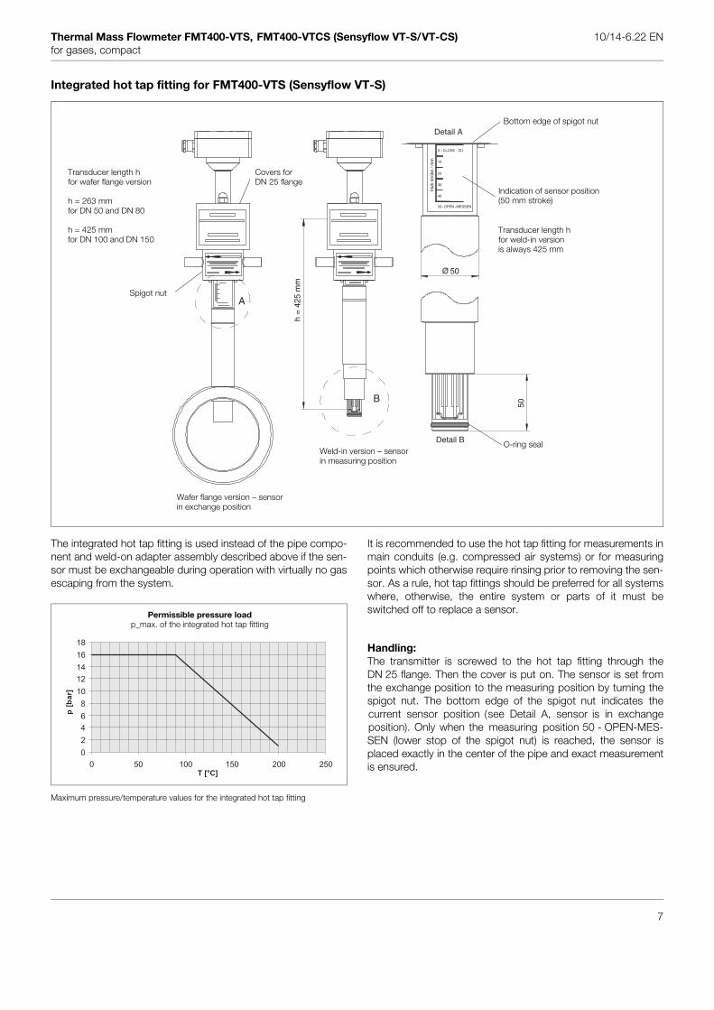
Integrated hot tap fitting for FMT400-VTS (Sensyflow VT-S)
The integrated hot tap fitting is used instead of the pipe compo-nent and weld-on adapter assembly described above if the sen-sor must be exchangeable during operation with virtually no gasescaping from the system.
Maximum pressure/temperature values for the integrated hot tap fitting
It is recommended to use the hot tap fitting for measurements inmain conduits (e.g. compressed air systems) or for measuringpoints which otherwise require rinsing prior to removing the sen-sor. As a rule, hot tap fittings should be preferred for all systemswhere, otherwise, the entire system or parts of it must beswitched off to replace a sensor.
Handling:The transmitter is screwed to the hot tap fitting through theDN 25 flange. Then the cover is put on. The sensor is set fromthe exchange position to the measuring position by turning thespigot nut. The bottom edge of the spigot nut indicates thecurrent sensor position (see Detail A, sensor is in exchangeposition). Only when the measuring position 50 - OPEN-MES-SEN (lower stop of the spigot nut) is reached, the sensor isplaced exactly in the center of the pipe and exact measurementis ensured.
h =
425
mm
Detail B
50
50
A
B
Hub
str
oke
/ mm
20
10
30
40
0 - CLOSE - ZU
50 -OPEN-MESSEN
Detail A
Transducer length hfor weld-in versionis always 425 mm
Transducer length hfor wafer flange version
h = 263 mm for DN 50 and DN 80
h = 425 mm for DN 100 and DN 150
Wafer flange version – sensorin exchange position
Weld-in version – sensor in measuring position
Covers for DN 25 flange
Indication of sensor position(50 mm stroke)
O-ring seal
Bottom edge of spigot nut
Spigot nut
Permissible pressure loadp_max. of the integrated hot tap fitting
0
2
4
6
8
10
12
14
16
18
0 50 100 150 200 250
T [°C]
p[b
ar]
7

Thermal Mass Flowmeter FMT400-VTS, FMT400-VTCS (Sensyflow VT-S/VT-CS) 10/14-6.22 ENfor gases, compact
FMT400-VTCS (Sensyflow VT-CS), hygienic versions
Measuring ranges at atmospheric pressure
Dimensional drawings (dimensions in mm)
FMT400-VTCS (Sensyflow VT-CS), hygienic version with pipe fitting S acc. to DIN 11851
Type of gas Air, nitrogen Oxygen Carbon dioxideOperating temperature -25...+150 °C - 25...60 °C - 25...150 °CNominal sizes:
DN 25DN 40DN 50DN 80
Standard measuring ranges0 (1.6) ... 160 kg/h0 (4) ... 430 kg/h0 (7) ... 700 kg/h0 (17) ... 1700 kg/h
Standard measuring ranges0 (1.6) ... 160 kg/h0 (4) ... 430 kg/h0 (7) ... 700 kg/h0 (17) ... 1700 kg/h
Standard measuring ranges0 (1.8) ... 180 kg/h0 (4) ... 440 kg/h0 (7) ... 730 kg/h0 (19) ... 1900 kg/h
Pipe component, hygienic versionwith pipe fitting S acc. to DIN 11851,Nominal pressure PN16 for DN 25, 40, 50; PN10 for DN 80
Transducer
DN A L L1 L2 ∅ D G25 196 182 140 42 28 × 1 Rd52 × 1/6“40 284 270 205 65 40 × 1 Rd62 × 1/6“50 344 330 265 65 52 × 1 Rd78 × 1/6“80 526 510 425 85 85 × 2 Rd110 × 1/4“
∅D
L1 L2
L
A
G12
0Z-
1893
6
Direction of flow
Direction of flow
Centre of pipe component
Rd 52 x 1/6"
2750
197
120
Z-18
937
125
58
8

Thermal Mass Flowmeter FMT400-VTS, FMT400-VTCS (Sensyflow VT-S/VT-CS) 10/14-6.22 ENfor gases, compact
FMT400-VTCS (Sensyflow VT-CS), hygienic version with FG flange
Pipe component, hygienic versionwith FG flange: FG 1, PN10
Transducer
DN L L1 L2 ∅ D F25 175 133 42 29 × 1,5 8340 270 205 65 42 × 2 10050 330 265 65 54 × 2 11080 510 425 85 85 × 2 142
The FG flanges on the pipe component’s process side are always smooth (without groove).
Ø D
L1
L
L2
120
F
Direction of flow
125
5877
120
255
Centreof pipe component
Direction of flow
9

Thermal Mass Flowmeter FMT400-VTS, FMT400-VTCS (Sensyflow VT-S/VT-CS) 10/14-6.22 ENfor gases, compact
Recommended steadying lengths according to DIN EN ISO 5167-1
To achieve the stated measuring accuracy, the steadying lengthsseen above must be provided. For combinations of inlet run dis-turbances, e. g. valve and reducer, you must always consider thelonger inlet run length. In confined spaces at the mounting loca-tion the outlet run length can be shortened to 3 x D. The reduc-tion of the minimum inlet run length, however, will impact on theachievable accuracy.
High repeatability of the measuring value is still provided. Undercertain circumstances, special calibration can be performed forinsufficient steadying lengths. For this purpose and in individualcases, consult the DKD Calibration Department at Alzenau.For gases with extremely low density (hydrogen, helium) thesteadying lengths must be doubled.
Expansion
X = 15
Reducer
X = 15
90° elbow
X = 20
Two 90° elbowin 1 level
X = 25
Two 90° elbowin 2 levels
X = 40
Valve/slide
X = 50
X D× 5 D×
Z-18938
Z-1
8939
Z-1
8940
Z-1
8941
Z-1
8942
Z-18943
Z-18944
10

Thermal Mass Flowmeter FMT400-VTS, FMT400-VTCS (Sensyflow VT-S/VT-CS) 10/14-6.22 ENfor gases, compact
Ordering information
Catalog No. Code EUR Deliv. timeTransducer FMT400-VTS V14222- 3155,00 6 wks.1 Characteristic curveSensor unitCeramic sensor (standard) 0 -Metal sensor (special) 1 -VTS, process technology version 1 494,00Operation temperatureStandard range -25...+150 °C 1 -Extended range (Ceramic sensor) -25...+300 °C 1) 2 631,00Measured mediumGases + gas mixtures (not for pure oxygen) 0 -Oxygen (only up to 150 °C) with O2 -certificate 1 1 584,00DVGW Certification (only up to 150 °C) 1 2 165,00H2, He (1.5 MPa max.; always with process gas calibration) 2) 3 757,00Material stainless steel 1.4571 (316Ti)Mounting length 263 mm (DN 25...DN 350) 3) 1 0 -Mounting length 425 mm (> DN 350...DN 700) 3) 2 0 271,00Mounting length 775 mm (> DN 700) 3) 3 0 876,00Analog output 4)4...20 mA, alarm < 3.5 mA 1 -4...20 mA, alarm > 22 mA 2 -0...20 mA 3 -1 Characteristic curve 1 -(Code Nos. measuring-point parameter see additional ordering information for calibration)
Additional ordering informationCode EUR Deliv. time
DKD Certificate 310 361,00Calibration with air on our DKD calibration bench(PTB approved DKD calibration facility No. 05701)DKD: German calibration service, PTB: German Physical and Technical Federal Institute
3.1 B Certificate material certificate (only for transducer) 30A 42,20
AccessoriesCatalog No. Code EUR Deliv. time
LKS-Adapter 7962828 122,00Local Communication Interface for parameterizationincl. Communication softwarePower supply unit 7962800 246,00housing for rail mounting 62.5 mm x 75 mm x 139 mmInput 230 V ACOutput 24 V DC / 2.5 A
1) Metal sensor max. 250 °C2) process gas calibration for other gases/gas mixtures on request 3) nominal size ranges when using pipe components or weld-on adapters without ball valve4) Changeable via LKS adapter
11

Thermal Mass Flowmeter FMT400-VTS, FMT400-VTCS (Sensyflow VT-S/VT-CS) 10/14-6.22 ENfor gases, compact
Ordering information
Catalog No. Code EUR Deliv. timePipe component design 2 for FMT400-VTS V14233- 690,00 6 wks.partial measuring sectionPN 40, material stainless steel 1.4571 (316Ti)(flange shape B1 according to EN 1092-1)Nominal size DN 25 Inner ∅ 28.5 1) 1 1 0 -Nominal size DN 40 43.1 1 2 0 47,40Nominal size DN 50 54.5 1 3 0 74,20ANSI 150 Ib, Sch 40 S, material stainless steel 1.4571 (316Ti)Nominal size ANSI 1" Inner ∅ 26.6 1) 2 A 0 -Nominal size ANSI 1 1/2" 40.9 2 B 0 47,40Nominal size ANSI 2" 52.6 2 C 0 74,20ANSI 300 Ib, Sch 40 S, material stainless steel 1.4571 (316Ti)Nominal size ANSI 1" Inner ∅ 26.6 1) 3 A 0 -Nominal size ANSI 1 1/2" 40.9 3 B 0 47,40Nominal size ANSI 2" 52.6 3 C 0 74,20
Additional ordering informationCode EUR Deliv. time
3.1 B Certificate, material certificate (only for pipe component) 30A 42,20
Ordering informationCatalog No. EUR Deliv. time
Weld-on adapter PN 40 for FMT400-VTS 6 wks.recommended from DN 150Material
stainless steel 1.4571 (316Ti) 7962500 228,001.0037 7962502 228,00
Weld-on adapter with ball valve/hot tap fitting for FMT400-VTSmaterial stainless steel 1.4571 (316Ti)Weld-on adapter with ball valve for pressureless, 7962832 945,00 non gas-tight applicationsWeld-on adapter with integrated hot tap fitting for nominal 7964131 2534,00 size DN 100 to DN 125/ANSI 4“ to 5“ and transducers of 425 mm, for pressure applications up to 16 bars and gas-tight applications, material 1.4571Weld-on adapter with integrated hot tap fitting for nominal 7964132 2534,00 size DN 150 to DN 300/ANSI 6“ to 12“ and transducers of 425 mm, for pressure applications up to 16 bars and gas-tight applications, material 1.4571Special pipe component for transducer FMT400-VTS
call 7962767 callDescription:"......................................................................................................................................................................"
3.1 B Certificate, material certificate (only for pipe component) 7962839 42,20
1) In order to achieve the specified measuring accuracy, the calibration of the transducer must be performed in the original pipe component DN25/1". If the transducer needs to be re-calibrated, it must be submitted together with the same pipe component.
12

Thermal Mass Flowmeter FMT400-VTS, FMT400-VTCS (Sensyflow VT-S/VT-CS) 10/14-6.22 ENfor gases, compact
Ordering information
Catalog No. Code EUR Deliv. timePipe component design 1 for FMT400-VTS V14232- 690,00 6 wks.wafer flange versionPN 40, material stainless steel 1.4571 (316Ti) Inner diameter (mm)Nominal size DN 40 43.1 1 2 0 47,40Nominal size DN 50 54.5 1 3 0 74,20Nominal size DN 80 82.5 1 4 0 133,00Nominal size DN 100 107.1 1 5 0 197,00Nominal size DN 150 159.3 1 6 0 499,00Nominal size DN 200 206.5 1 7 0 790,00ANSI 150 Ib, Sch 40 S, material stainless steel 1.4571 (316Ti)Nominal size ANSI 1 1/2" 40.9 2 B 0 47,40Nominal size ANSI 2" 52.6 2 C 0 74,20Nominal size ANSI 3" 78.0 2 D 0 133,00Nominal size ANSI 4" 102.4 2 E 0 197,00Nominal size ANSI 6" 154.2 2 F 0 499,00Nominal size ANSI 8" 202.7 2 G 0 790,00ANSI 300 Ib, Sch 40 S, material stainless steel 1.4571 (316Ti)Nominal size ANSI 1 1/2" 40.9 3 B 0 47,40Nominal size ANSI 2" 52.6 3 C 0 74,20Nominal size ANSI 3" 78.0 3 D 0 133,00Nominal size ANSI 4" 102.4 3 E 0 197,00Nominal size ANSI 6" 154.2 3 F 0 499,00Nominal size ANSI 8" 202.7 3 G 0 790,00Ball valve or hot tap fittingwithout 0 -Pipe component with ball valve for pressureless applications, non gas-tight 1 721,00 material stainless steel 1.4571 (316Ti)Pipe component with integrated hot tap fitting for nominal size DN 50 4 2137,00 or DN 80 (ANSI 2"/3") and transducer of 263 mm, for pressure applications up to 16 bars and gas-tight applications, material stainless steel 1.4571 (316Ti), flanges PN 40Pipe component with integrated hot tap fitting for nominal size DN 100 5 2256,00 or DN 150 (ANSI 4"/6") and transducer of 425 mm, for pressure applications up to 16 bars and gas-tight applications, material stainless steel 1.4571 (316Ti), flanges PN 40
Additional ordering informationCode EUR Deliv. time
3.1 B Certificate, material certificate (only for pipe component) 30A 42,20
13

Thermal Mass Flowmeter FMT400-VTS, FMT400-VTCS (Sensyflow VT-S/VT-CS) 10/14-6.22 ENfor gases, compact
Ordering information
Catalog No. Code EUR Deliv. timeTransducer FMT400-VTCS V14222- 3155,00 6 wks.Hygienic version 1 0 4 0 -Material stainless steel, mounting length 120 mm,ConnectionMale part screw connection S acc. to DIN 11851, nominal pressure PN 16 6 -FG flange, nominal pressure PN 10 8 -Measured mediumGases + gas mixtures (not for pure oxygen) 0 -Oxygen with O2 certificate 1) 1 584,00Analog output 2)4...20 mA, alarm < 3.5 mA 1 -4...20 mA, alarm > 22 mA 2 -0...20 mA 3 -1 Characteristic curve 1 -(Code Nos. measuring-point parameter see additional ordering information for calibration)DKD Certificate 310 361,00Calibration with air on our DKD calibration bench(PTB approved DKD calibration facility No. 05701)DKD: German calibration service, PTB: German Physical and Technical Federal Institute
Additional ordering informationCatalog No. Code EUR Deliv. time
Pipe component for FMT400-VTCS V14234- - 6 wks.Hygienic versionas partial measuring section, material stainless steelConnectionMale part screw connection S acc. to DIN 11851, nominal pressure PN 16 6 0 -FG flange, nominal pressure PN 10 8 0 -Nominal sizeDN 25 1 456,00DN 40 2 493,00DN 50 3 520,00DN 80 (max. 10 bar) 4 557,00
AccessoriesCatalog No. EUR Deliv. time
LKS-Adapter 7962828 122,00Local Communication Interface for parameterizationincl. Communication softwarePower supply unit 7962800 246,00housing for rail mounting 62.5 mm x 75 mm x 139 mmInput 230 V ACOutput 24 V DC / 2.5 A
1) not for FG flange2) Changeable via LKS adapter
14

Thermal Mass Flowmeter FMT400-VTS, FMT400-VTCS (Sensyflow VT-S/VT-CS) 10/14-6.22 ENfor gases, compact
Additional ordering information for calibration
FMT400-VTS Code EUR Deliv. timeMeasuring point parameterGas 1, Vol % (clear text) 511 -Gas 2, Vol % (clear text)Gas 3, Vol % (clear text)Gas 4, Vol % (clear text)Gas 5, Vol % (clear text)Gas 6, Vol % (clear text)Gas 7, Vol % (clear text)Gas 8, Vol % (clear text)Gas 9, Vol % (clear text)Gas 10, Vol % (clear text) 516 -
(clear text) 517 -Sum 100 %
Operating temperature (clear text) 512 -Operating pressure (clear text) 513 -Nominal size, pipe inner diameter (clear text) 518 -Measuring range (clear text) 514 -Unit (clear text) 515 -Standard state (e.g. 0 °C, 1013 mbar) 519 -Adjusted measuring range (clear text) 520 -
Add the 3-digit Code No to the Catalog No.
15
Thermal Mass Flowmeter FMT400-VTS, FMT400-VTCS (Sensyflow VT-S/VT-CS) 10/14-6.22 ENfor gases, compact
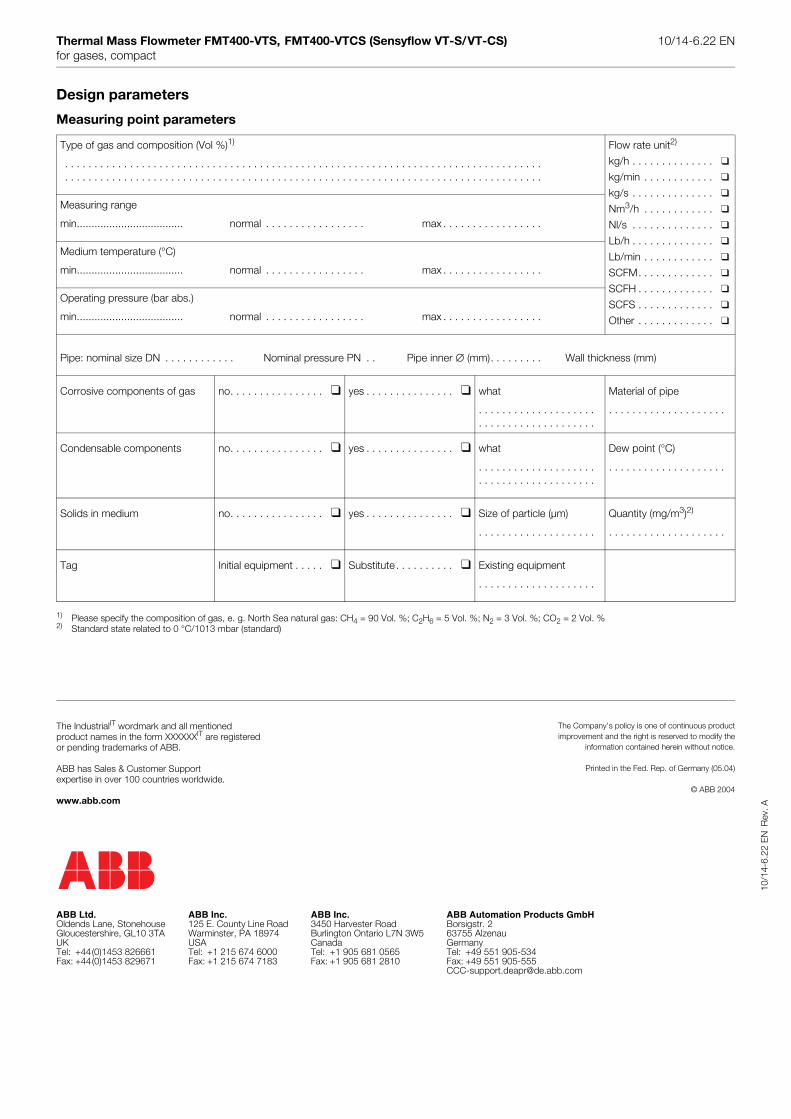
Design parameters
Measuring point parameters
1) Please specify the composition of gas, e. g. North Sea natural gas: CH4 = 90 Vol. %; C2H6 = 5 Vol. %; N2 = 3 Vol. %; CO2 = 2 Vol. %2) Standard state related to 0 °C/1013 mbar (standard)
Type of gas and composition (Vol %)1)
. . . . . . . . . . . . . . . . . . . . . . . . . . . . . . . . . . . . . . . . . . . . . . . . . . . . . . . . . . . . . . . . . . . . . . . . . . . . . . . . . . . . . . . . . . . . . . . . . . . . . . . . . . . . . . . . . . . . . . . . . . . . . . . . . . . . . . . . . . . . . . . . . . . . . . . . . . . . . . . . . .
Flow rate unit2)
kg/h . . . . . . . . . . . . . .
kg/min . . . . . . . . . . . .
kg/s . . . . . . . . . . . . . .
Nm3/h . . . . . . . . . . . .
Nl/s . . . . . . . . . . . . . .
Lb/h . . . . . . . . . . . . . .
Lb/min . . . . . . . . . . . .
SCFM. . . . . . . . . . . . .
SCFH . . . . . . . . . . . . .
SCFS . . . . . . . . . . . . .
Other . . . . . . . . . . . . .
Measuring range
min.................................... normal . . . . . . . . . . . . . . . . . max . . . . . . . . . . . . . . . . .
Medium temperature (°C)
min.................................... normal . . . . . . . . . . . . . . . . . max . . . . . . . . . . . . . . . . .
Operating pressure (bar abs.)
min.................................... normal . . . . . . . . . . . . . . . . . max . . . . . . . . . . . . . . . . .
Pipe: nominal size DN . . . . . . . . . . . . Nominal pressure PN . . Pipe inner ∅ (mm). . . . . . . . . Wall thickness (mm)
Corrosive components of gas no. . . . . . . . . . . . . . . . yes . . . . . . . . . . . . . . . what
. . . . . . . . . . . . . . . . . . . .
. . . . . . . . . . . . . . . . . . . .
Material of pipe
. . . . . . . . . . . . . . . . . . . .
Condensable components no. . . . . . . . . . . . . . . . yes . . . . . . . . . . . . . . . what
. . . . . . . . . . . . . . . . . . . .
. . . . . . . . . . . . . . . . . . . .
Dew point (°C)
. . . . . . . . . . . . . . . . . . . .
Solids in medium no. . . . . . . . . . . . . . . . yes . . . . . . . . . . . . . . . Size of particle (µm)
. . . . . . . . . . . . . . . . . . . .
Quantity (mg/m3)2)
. . . . . . . . . . . . . . . . . . . .
Tag Initial equipment . . . . . Substitute. . . . . . . . . . Existing equipment
. . . . . . . . . . . . . . . . . . . .
10/1
4-6.
22 E
NR
ev. A
ABB Inc.3450 Harvester RoadBurlington Ontario L7N 3W5CanadaTel: +1 905 681 0565Fax: +1 905 681 2810
ABB Ltd.Oldends Lane, StonehouseGloucestershire, GL10 3TAUKTel: +44(0)1453 826661Fax: +44(0)1453 829671
ABB Automation Products GmbHBorsigstr. 263755 AlzenauGermanyTel: +49 551 905-534Fax: +49 551 [email protected]
ABB Inc.125 E. County Line RoadWarminster, PA 18974USATel: +1 215 674 6000Fax: +1 215 674 7183
The IndustrialIT wordmark and all mentioned product names in the form XXXXXXIT are registered or pending trademarks of ABB.
ABB has Sales & Customer Supportexpertise in over 100 countries worldwide.
www.abb.com
The Company’s policy is one of continuous productimprovement and the right is reserved to modify the
information contained herein without notice.
Printed in the Fed. Rep. of Germany (05.04)
© ABB 2004


