Embed Size (px)
Citation preview

1445
Critical NATM underground stations for the Bangkok MRTA blue line extension project
Chat Chaiwonglek & Suchatvee Suwansawat Ladkrabang Underground and Tunnelling Innovation Center (LUTIC), Department of Civil Engineering, Faculty of Engineering, King Mongkut’s Institute of Technology Ladkrabang, Bangkok, Thailand
SYNOPSIS: The second phase subway system in Bangkok known as the MRTA Blue Line Extension will be constructed to reduce traffic problem in the southern part of the metropolitan area. There are four underground stations needed to be excavated along the new subway alignment that two of them have to be constructed underneath very sensitive areas of Bangkok such as the old China town and the historical area close to the Royal Palace where construction space is very limited and cut and cover method is prohibited. Besides, aged residential and commercial buildings are poorly supported and its traffic is very dense. Therefore analysis and design of the stations is crucial to determine an optimum solution to serve both functional requirements and environmental concerns. To achieve the objectives, NATM stations are introduced for the first time in Bangkok subsoil condition combining with Cut and Cover method. All geological and geographical constraints, design criteria and analysis including Finite Element Method of the critical underground stations in this project is presented in this paper.
1. INTRODUCTION
The Mass Rapid Transit Authority of Thailand (MRTA) has initiated a new line connected to the existing Blue line in the southern part of Bangkok.
The new line, called the MRTA Blue line Extension, consists of 5 km-underground structure and 22 km-elevated structure. The underground section is shown in Figure 1.
The Initial System
Underground System
Elevated System
Figure 1. Bangkok MRTA blue line extension
World Tunnel Congress 2008 - Underground Facilities for Better Environment and Safety - India

1446
The underground section comprises 4 underground stations, two station boxes and two NATM stations, which are Wat Mangkon station, Wang Burapha station, Sanamchai station and Itsaraphap station. All stations located at around the Old City Area (also widely known as the Rattanakosin Island) and both Wang Burapha station and Sanamchai station are inside the Rattanakosin Island, are required to be constructed with minimized environmental impact method that is NATM (Figure 2). These NATM stations are designed and analyzed by procedure further described in this paper.
2. GEOLOGICAL CONDITION
NATM stations are located mostly within Bangkok clays which can be separated into seven distinct layers based on field exploration and laboratory tests, as described in Table 1. The subsoils profile down to maximum drilling depth of approximately 60-65 meters along route of Blue line south extension is shown in Figure 3. Calculation procedures of NATM stations using Finite Element Method required soil parameters in the soil material model namely “Hardening Soil” (HS). In contrast to an elastic perfectly-plastic model, the yield surface of a hardening plasticity model is not fixed in principal stress space, but it can expand due to plastic straining. Distinction can be made between two
main types of hardening, namely shear hardening and compression hardening. Shear hardening is used to model irreversible strains due to primary deviatoric loading. Compression hardening is used to model irreversible plastic strains due to primary compression in oedometer loading and isotropic loading. Both types of hardening are contained in the herein used material model HS. The use of advance soil model is mentioned above. Advance soil parameters have to be determined, of which some can be chosen at first sight out of the provided laboratory testing results. For the determination of stiffness and cohesion back-calculation of unconsolidated undrained triaxial laboratory test (UU test) has to be done because triaxial tests fit best for the determining input parameter for HS model The water pressure in soil is not just normal hydrostatic pressure that rises up from surface to deeper lever. At depth greater than 6 meters, a non-hydrostatic piezometric pressure is expected due to deep well pumping. The piezometric reading in the cohesive soil strata may not have been stabilized, giving rise to greater scatter in the plot. As for the measurements in the sandy soil layers, the pore water pressure on top of the first sand (at depth of about 20 m) is almost zero. Figure 4 shows a typical pore water pressure profile in Bangkok, indicating severe pumping in the sand layer and this behaviour can simulated in Finite Element analyses.
WANG BURAPHA STATION
SANAM CHAI STATIONWAT MANGKON
STATION
ITSARAPHAP STATIONHUA LAMPHONG STATION
(Existing Station)
Interior Rattanakosin Island
Exterior Rattanakosin Island
Rattanakosin Island Thonburi part
cut & cover station
NATM station
Figure 2. Rattanakosin island area and location of stations

1447
The NATM has chosen the minimized environmental impact method, so the analyses of ground deformation which effects the existing nearby structure is taken in to account. The Finite Element analysis can model the surrounding environment, the stiffness of pile foundation such as single pile, pile group and raft foundation below existing building also has to be determined.
In some case of calculation phase, ground improvement need to be used and its parameter will be determined in Finite Element analysis particularly in sand layer. The ground strengthening by jet grouting might not be suitable in sand layer and ground freezing should be applied in this case.
Table 1. General soil description
Basic Engineering Properties
Stratum
Thickness of stratum
(m)
Physical Characteristic
Water Content (%)
Cu (kPa) N-Value
1. Weathered Crust and Backfill Material 2-5 Light to yellowish gray in
color 10-35 - 2-21
2. Very Soft to Soft Clay 8-10 Medium gray to dark gray 60-105 10-25 -
3. Medium Stiff Clay 3-4 Dark gray to brownish gray 31-62 26-47 -
4. Stiff to Hard Clay ~10 Yellowish to light grayish brown 15-32 75-162 9-35
5. Medium Dense to Very Dense Sand ~5 Yellowish to grayish brown 12-25 - >20
6. Very Stiff to Hard Clay 10-12 Light gray to grayish brown 15-22 - >30
7. Very Dense Sand >10 Yellowish brown to brownish gray - - >50
Figure 3. Soil profile along the Bangkok MRTA blue line south extension

1448
Figure 4. Typical piezometric pressure profile in Bangkok
3. NEW AUSTRIAN TUNNELLING METHOD
(NATM)
The New Austrian Tunneling Method (NATM) is used for minimizing excavation area on the ground surface corresponding to the constraint of construction in Rattanakosin Island. This method has been adopted in the construction of stations that are Wang Burapha station and Sanamchai station, because both stations are located inside Ratanakosin Island area. The NATM has made a significant contribution to tunneling worldwide. A significant application of NATM has been in the Frankfurt Metro (1968) which was constructed in soft ground. Two tunnels were driven underneath major structures in the city where an overburden thickness of only 6 meters to the foundations existed. Settlements of only 35 millimeters were measured during construction of the tunnels. This success led to the use of NATM for similar construction projects and, at present, even station tunnels of 200 m2 cross-sectional area are constructed by this method. Additionally, at present the Metro 4 of Budapest, Hungary also adopts the NATM for constructing two stations in soft ground with high
water pressure and Vienna Metro U2/1 station was successfully excavated using NATM The concept of NATM in soft ground is to provide the immediate tunnel support by closing the invert quickly to prevent the movement of material under gravity. This should ultimately control the level of surface movement which is particularly important in urban areas where even very small settlements can be unacceptable. It is important for the face to remain stable and the soil arches, spanning the face, provide stability. Their load bearing capacity depends on their effective span and the shear strength of the ground. In its construction procedure, the ground must possess sufficient cohesion to give it a stand-up time in the excavation of at least 90 minutes with an advance of 1 m. Not all soils provide this requirement in particular sands and gravels. Groundwater hazard can accentuate this particular problem of ground control. As a result, soil reinforcement techniques and dewatering methods are typically employed in association with NATM tunneling in soft ground. Such methods include forepoling and spiling, grouting, dewatering by well points, compressed air and ground freezing, etc, and

1449
these promote face stability and groundwater control which are so important to the NATM construction process. Key features of the NATM design philosophy are:
• The strength of the ground around a tunnel is deliberately mobilized to the maximum extent possible.
• Mobilization of ground strength is achieved by allowing controlled deformation of the ground.
• Initial primary support is installed having load-deformation characteristics appropriate to the ground conditions, and installation is timed with respect to ground deformations.
• Extensive instrumentation is installed to monitor deformations in the initial support system, as well as to form the basis of varying the initial support design and the sequence of excavation.
Key features of NATM construction methods are:
• The tunnel is sequentially excavated and supported, and the excavation sequences can be varied.
• The initial ground support is provided by shotcrete in combination with fibre or welded-wire fabric reinforcement, steel arches (usually lattice girders), and sometimes ground reinforcement (e.g., soil nail, spiling)
• The permanent support is usually (but not always) a cast-in-place concrete lining.
4. CONSTRAINTS
The constraint of NATM stations in this project are to construct underneath very congested area, limit of settlements, traffic control and the strict requirements of Rattanakosin Island. The geometry and feature of each station is often changing to
accommodate the optimum solution based upon useable area inside station under minimum and maximum requirement of the NFPA (National Fire Protection Association) standards and codes, and area of excavation at ground surface. The Architect was using more skill and experience working with expert engineer to accommodate those requirements. By the way the optimum solutions were the combination of NATM and cut and cover method. This feature called NATM and partial cut and cover, is using the narrow station box outside the road for which permit was got in the earlier time and was convenient for management of any utility system and ventilation system. A typical cross- sections of both NATM stations are shown in Figure 5.
5. DESIGN CRITERIA
The design of the structure of the station follows the design criteria of technical report and meeting NATM specifications. With respect to Standard, Loading etc.
5.1 Standards and codes of practice
The design of NATM station has been designed in accordance with all applicable portions of the following standard and codes.
ASTM American Society for Testing Materials
BS British Standard
CEN European Committee for Standardization
DIN German Industrial Standard
EN European Standard
ENV European Pre-Standard
ISO International Organization for Standardization

1450
(a) (b)
Figure 5. Typical cross-section of NATM stations (a) Wang Burapha station (b) Sanamchai station
5.2 Loading
Loading on the station can be separated into 2 cases, temporary case and permanent case. The temporary case during construction can be followed (Table 2). A loading from the existing building is taken in to account in the calculation step based up on the number of storeyed buildings. The permanent case includes internal slab and stair case subjected to pedestrian live loading of 5 kPa. In plant room areas a live load of 10 kPa is
allowed for, increasing to 25 kPa for transformer room. Train loads are based on the maximum works train axle load of 175 kN (Figure 6). In reality, due to the substantial nature of the base slab in station box, vertical train loads were not critical in the station design. However, all vertical support elements in the station, such as walls and column are to be protected from train impact.
Table 2. Temporary load during construction
Overburden 1.0 1.5 2.0 2.5 3.0 3.5 4.5 More than 4.5
Road traffic load (kN/m2) 35.5 28.5 20.5 15.0 12.0 11.5 10.5 10.0

1451
Figure 6. Load of standard one car train 5.3 Durability
The stations are all other permanent underground structures on the project are to have a design life of 120 years.
6. CALCULATION AND RESULT
Along the alignment of two underground NATM stations, excavation areas are planned, namely Wang Burapha station and Sanamchai station. Whilst at Wang Burapha station the two TBM tunnels are placed beside the cut and cover box in stacked position, only connected with crossway to main station construction, at Sanamchai station only one TBM tunnel is located, beside the cut and cover
box hiding the second one inside. Additionally a short-length tunnel above the exposed TBM tunnel provides a complex underground construction. The result was obtained from the calculation step by Finite Element analysis. (A) Wang Burapha station
Wang Burapha station is placed very closed to existing, mostly 4 storey building For the construction of cut and cover box existing buildings have to be ruptured followed by bringing down the diaphragm walls and excavating the cut and cover box area in pile group support soil layers.
Figure 7. Plan of construction area around Wang Burapha station
NATM Tunnel
Station box
(1) Dimensions are in mm for one car
(2) Axle Load P = 175 kN for crush load
(3) Axle Load P = 100 kN for empty train based on 4kN/m2 over 3.2 m width and 23.5 m length
1452
The stacked TBM tunnels are directly covered by a road on the surface. Where the lower tunnel, constructed at first-is placed partly in stiff clay and sand, the second upper tunnel is located in soft clay and stiff clay. The concerning layers of sand for the lower tunnel and the layers of soft clay for the upper tunnel will be stiffened by ground improvement. For the Finite Element analysis two characteristic cross sections- CS A and CS B- have been analyzed, depicted in Figure 8 and Figure 9.
The analysis of each cross section will follow main construction sections, namely
- Cut & Cover box excavation steps
- NATM works
- Finishing Cut & Cover box
- Consolidation process after 200 / 600 / 1800 days
Figure 8. Wang Burapha Station – Geometry Cross section A
Figure 9. Wang Burapha Station – Geometry Cross section B

1453
For the NATM excavation procedure the construction of the lower tunnel was considered first, due to practical reasons. The following regular excavation sequence (E-S) was taken into account, (Figure 10). Intermediate calculation steps concern about the grouting of the lower soil, improvements and removed of the lower temporary struts in regard to practicability of NATM excavation were considered earlier. The excavation sequence is divided into 2 main areas, E-S 2 and E-S 3, and each area into 3 sub-sequences. After fully excavation NATM tunnel, surface settlement increased approx. 7 millimeters to max 20 millimeters. The upper tunnel is considered like lower tunnel and after excavation, surface settlement increased approx. 3 to max 23 millimeters.
(B) Sanamchai station
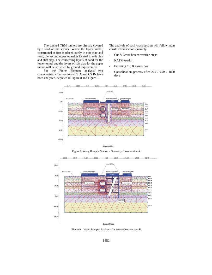
Opposite to Wang Burapha station in the neighborhood of Sanamchai station only few building exists. Whole of the construction including cut and cover box and left-sided tunnel is taking place in the up-coming soil layers. No influence of pile-group supported soil cluster is evident. The base level of the cut and cover box is placed in hard clay formation whereas main of the NATM tunnels, with excavation diameters of approx. 10 to 11 meters, are laid in stiff clay. For the station centre including the escalator tunnel a jet
grouted soil improvement area above escalator tunnel is planned in soft clay. The cut and cover box width is approx. 10 metres. For the Finite Element Analysis two representative cross sections - CS A and CS B - have been analysed, depict in Figures 12 and 13. For each cross section the geological assembling of the southern station part is chosen. Figure 11 gives an overview of the chosen cross sections. The analysis of each cross section will follow main construction sections, namely
- Cut & Cover box excavation steps
- NATM works
- Finishing Cut & Cover box
- Consolidation process after 200 / 600 / 1800 days
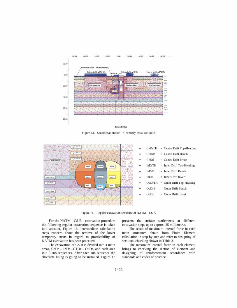
For the NATM - CS A - excavation procedure the following regular excavation sequence is taken into account, Figure 14. Intermediate calculation steps concern about the remove of the lower temporary struts in regard to practicability of NATM excavation has been preceded. The excavation of CS A is divided into 3 main areas, CeDr – InDr – OuDr, and each area into 3 sub-sequences. Figure 15 presents the surface settlements at different excavation steps up to approx. 30 millimetres.
(a) (b)
Figure 10. Regular excavation sequence of NATM – (a) lower tunnel and (b) upper tunnel

1454
Figure 11. Plan of construction area around Sanamchai station
Figure 12. Sanamchai Station – Geometry Cross section A
Station box
NATM Tunnel
1455
Figure 13. Sanamchai Station – Geometry cross section B
Figure 14. Regular excavation sequence of NATM – CS A For the NATM - CS B - excavation procedure the following regular excavation sequence is taken into account, Figure 16. Intermediate calculation steps concern about the remove of the lower temporary struts in regard to practicability of NATM excavation has been preceded. The excavation of CS B is divided into 4 main areas, CeDr – InDr –CTDr - OuDr, and each area into 3 sub-sequences. After each sub-sequence the shotcrete lining is going to be installed. Figure 17
presents the surface settlements at different excavation steps up to approx. 25 millimetres. The result of maximum internal force in each main structures obtain from Finite Element calculation in step by step and refer to designing of sectional checking shown in Table 3. The maximum internal force in each element brings to checking the section of element and designing of reinforcement accordance with standards and codes of practice.
• CeDrTH = Centre Drift Top-Heading
• CeDrB = Centre Drift Bench
• CeDrI = Centre Drift Invert
• InDrTH = Inner Drift Top-Heading
• InDrB = Inner Drift Bench
• InDrI = Inner Drift Invert
• OuDrTH = Outer Drift Top-Heading
• OuDrB = Outer Drift Bench
• OuDrI = Outer Drift Invert

1456
Figure 15. Drift excavations – surface settlements
Table 3. Maximum internal force in diaphragm wall and NATM lining
Maximum Internal force
Element
Thickness of Element
(mm) Bending Moment
(kN-m)
Shear
(kN)
Axial
(kN)
D-wall BS11* 1000, 1200 1922,-1700 1320 2830
D-wall BS12* 1000,1200 1980,-1487 1210 2850
NATM final lining
BS11* 600 115,-548 - 1184
NATM final lining
BS12* 600 -419 - 917
*BS11 = Wang Burapha Station, BS12 = Sanamchai Station

1457
Figure 16. Regular excavation sequence of NATM – CS B
Figure 17. Drift excavations – surface settlements
7. CONCLUSION
The design and analysis of NATM stations in the Bangkok MRTA Blue Line Extension Project encounters many general constraints such as to construct stations underneath very crowded area, traffic problem, the requirement of the Rattanakosin Island to limit excavation area on the ground surface, and required safety of evacuation areas. All of this makes this project a very challenging project
in an urban area. As a result, the design of station geometry needed high-skill engineering experience joining with skillful architecture work to accommodate those requirements. Furthermore, structural and geotechnical analyses to investigate effect to adjacent underground and surface structure is taken into account. The difficulties caused by construction methods and procedures needed to be considered in a case-by-case basis. Although
• CeDrTH = Centre Drift Top-Heading • CeDrB = Centre Drift Bench • CeDrI = Centre Drift Invert • InDrTH = Inner Drift Top-Heading • InDrB = Inner Drift Bench • InDrI = Inner Drift Invert • CTODTH = Concourse Tunnel Outer Drift Top-Heading • CTODB = Concourse Tunnel Outer Drift Bench • CTID = Concourse Tunnel Inner Drift • OuDrTH = Outer Drift Top-Heading • OuDrB = Outer Drift Bench • OuDrI = Outer Drift Invert

1458
NATM has been used successfully for construction of subway station for decades, it is adopted for the first time in Bangkok underground construction that required extensive knowledge of design and analysis. More over the interface of both stations ie NATM combining with cut and cover method which make construction in the future more difficult. The connection between NATM tunnel and cut and cover box as refered to the detail design should be re-analysed to consider and design the appropriate opening and connection structure. The risk analysis was also studied in this project considering all constraints and the construction method. Design criteria, design specification and standards including the good collection and usage of existing information are also needed for their importance in the design procedure.
REFERENCES
1. BMTC, 2007. “Draft Definitive Design Report.” MRTA Blue Line Extension Project. Preparation of Tender Document.
2. BMTC, 2007. “Geotechnical Investigation Report, Main Report.” Feasibility Study. MRTA Blue Line Extension Project. Preparation of Tender Document.
3. BMTC, 2007. “Technical Paper, Design Criteria.” MRTA Blue Line Extension Project. Preparation of Tender Document.
4. BMTC, 2007. “Calculation Report (under preparation).” MRTA Blue Line Extension Project. Preparation of Tender Document.
5. BMTD Consortium, 2006. “Blue Line Extension Project Tender Drawings.” MRTA Blue Line Extension Project, Preparation of Tender Document.
6. Photayanuvat, C., Flicke, J., Hollmann, F., 2006. “Outline Design of the Blue Line South Underground Section – Extension of the Existing Bangkok MRT Subway Line” International Symposium on Underground Excavation and Tunnelling, Bangkok, Thailand, pp. 85-96.
7. Suwansawat, S., 2004. “Construction Planning of the Second Phase Subway System to the Southern Bangkok.” Proc. the 22nd Conference of Asean Federation of Engineering Organizations (CAFEO), Myanmar.
BIOGRAPHICAL DETAILS OF THE AUTHORS
“Chat Chaiwonglek graduated in Civil Engineering from the King Mongkut’s Institute of Technology Ladkrabang (KMITL) in 2004. From 2004 to 2006 he worked for Nawarat Pattanakan Public Company as a geotechnical engineer for underground construction and tunneling project. In 2007 he
joined D2 Consult Asia Company as a senior geotechnical engineer, designing of underground stations for MRTA Blue Line Extension Project. And present he is pursuing his Doctoral Degree on Civil Engineering at KMITL”.
“Assoc. Prof. Dr. Suchatvee Suwansawat graduated in Civil and Environmental Engineering from Massachusetts Institute of Technology in 2002. He emphasize in underground construction Technology and tunneling researches including ground movement problems induced by tunneling,
underground construction technology, cost estimation, information technology for underground construction”.