Embed Size (px)
Citation preview

Amamix���� - Amaprop����Operating instructions1592.811-10
Mounting / Fastening instructionsInstallation Parts / Accessories
- Geared Version -
I
These operating instructions contain fundamental information andprecautionary notes. Please read the manual thoroughly before installing oroperating the unit.These operating instructions must always be used in conjunction with theoperating instructions of the mixer and any other supplementary operatinginstructions concerning the mixer itself or its components.
These operating instructions also contain fundamental information aboutthe installation and operation of the mixer accessories.The responsibility for ensuring compliance with all regulations in force atthe place of installation – also by any temporary labor assisting with theinstallation work – lies with the user. Accessories must only be used inaccordance with their designated purpose and only on the KSB mixer(s) forwhich they are intended.Their use on any other type of mixer of KSB origin or otherwise is notpermitted.
dent No: 01 059 147
KSB
2
Amamix���� - Amaprop����KSB
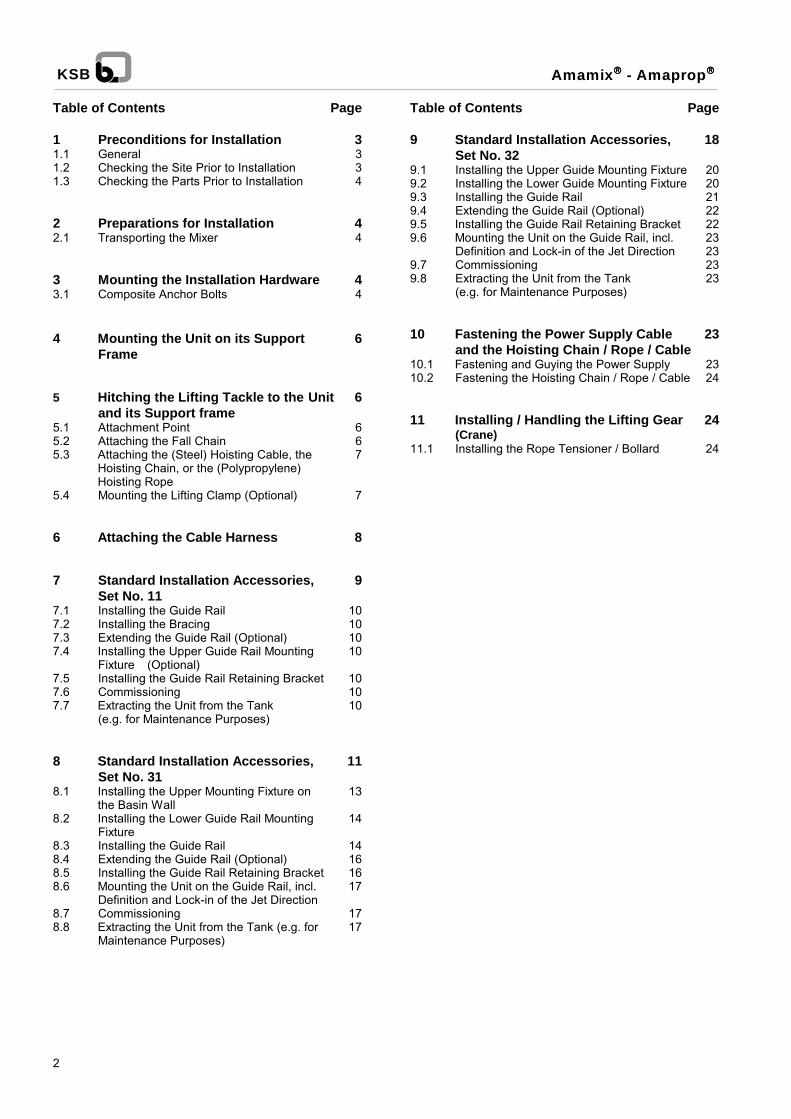
Table of Contents Page
1 Preconditions for Installation 31.1 General 31.2 Checking the Site Prior to Installation 31.3 Checking the Parts Prior to Installation 4
2 Preparations for Installation 42.1 Transporting the Mixer 4
3 Mounting the Installation Hardware 43.1 Composite Anchor Bolts 4
4 Mounting the Unit on its Support 6Frame
5 Hitching the Lifting Tackle to the Unit 6and its Support frame
5.1 Attachment Point 65.2 Attaching the Fall Chain 65.3 Attaching the (Steel) Hoisting Cable, the 7
Hoisting Chain, or the (Polypropylene)Hoisting Rope
5.4 Mounting the Lifting Clamp (Optional) 7
6 Attaching the Cable Harness 8
7 Standard Installation Accessories, 9Set No. 11
7.1 Installing the Guide Rail 107.2 Installing the Bracing 107.3 Extending the Guide Rail (Optional) 107.4 Installing the Upper Guide Rail Mounting 10
Fixture (Optional)7.5 Installing the Guide Rail Retaining Bracket 107.6 Commissioning 107.7 Extracting the Unit from the Tank 10
(e.g. for Maintenance Purposes)
8 Standard Installation Accessories, 11Set No. 31
8.1 Installing the Upper Mounting Fixture on 13the Basin Wall
8.2 Installing the Lower Guide Rail Mounting 14Fixture
8.3 Installing the Guide Rail 148.4 Extending the Guide Rail (Optional) 168.5 Installing the Guide Rail Retaining Bracket 168.6 Mounting the Unit on the Guide Rail, incl. 17
Definition and Lock-in of the Jet Direction8.7 Commissioning 178.8 Extracting the Unit from the Tank (e.g. for 17
Maintenance Purposes)
Table of Contents Page
9 Standard Installation Accessories, 18Set No. 32
9.1 Installing the Upper Guide Mounting Fixture 209.2 Installing the Lower Guide Mounting Fixture 209.3 Installing the Guide Rail 219.4 Extending the Guide Rail (Optional) 229.5 Installing the Guide Rail Retaining Bracket 229.6 Mounting the Unit on the Guide Rail, incl. 23
Definition and Lock-in of the Jet Direction 239.7 Commissioning 239.8 Extracting the Unit from the Tank 23
(e.g. for Maintenance Purposes)
10 Fastening the Power Supply Cable 23and the Hoisting Chain / Rope / Cable
10.1 Fastening and Guying the Power Supply 2310.2 Fastening the Hoisting Chain / Rope / Cable 24
11 Installing / Handling the Lifting Gear 24(Crane)
11.1 Installing the Rope Tensioner / Bollard 24

3
Amamix���� - Amaprop����KSB
1 Preconditions for Installation1.1 General
- Safety
This operating manual contains fundamental instructionsto be observed in connection with installation, operationand servicing. It is therefore imperative that this manualbe read prior to installation and commissioning by thefitter and the technical personnel / operators concerned,and it must always be kept available at or near the mixer.
Not only the general safety instructions contained in thischapter must be complied with, but also all special safetyinstructions included in other parts of this manual.
- Marking of instructions
All safety instructions included in this manual, thenonobservance of which could result in a hazard topersons involved, are preceded by the general hazardsymbol, i.e.:
Safety sign W9 in accordance with DIN 4844 � W9,Warnings about electrical hazards are preceded by thesymbol:
Safety sign W8 in accordance with DIN 4844 � W8,
All safety instructions in this user's manual, thenonobservance of which could jeopardize either the mixeritself or its safe operation, are preceded by the word
Caution
•••• Personnel qualification and training
All personnel involved in the operation, maintenance,inspection or installation of the mixer must be dulyqualified for the work in question. The personnel'sresponsibilities, competence and supervision must beclearly defined by the user. To the extent that thepersonnel in question is not already in possession of therequired skills and know-how, appropriate training andinstruction must be provided. The manufacturer / supplierwill provide such training, if necessary, at the user'srequest. The user is also responsible for ensuring that thecontents of this operating manual are fully understood bythe relevant personnel.
• Hazards resulting from noncompliance with thesafety instructions
Noncompliance with these safety instructions mayjeopardize the safety of people, property, the environmentand the mixer itself. Noncompliance with these safetyinstructions will also lead to the forfeiture of any and allrights to claims for damages.
Specifically, noncompliance may, for example, result in:
- failure of essential mixer and/or plant functions;- danger of injury caused by electrical shock,
mechanical impact or chemical exposure;- pollution of the environment due to leakage of
hazardous substances.
• Safety consciousness
It is imperative to comply with the safety instructionscontained in this manual, with the relevant nationalaccident prevention regulations, and with the user�s ownprocess, operating and safety specifications.
• Safety instructions for the user / operator
Take all necessary precautions to preclude electricalhazards. (For more information, refer to the stipulationsissued by your local power utility.)
• Safety instructions for maintenance, inspectionand installation work
The user is responsible for ensuring that all maintenance,inspection and installation work be carried out by dulyauthorized, adequately qualified, specialized personnelwho are thoroughly familiar with the contents of theseoperating instructions.
As a matter of principle, all work to be performed on themixer may only be executed with the mixer in adeenergized condition. The shutdown procedure fortaking the mixer out of service, as described in thismanual, must be strictly adhered to.
Mixers used for handling hazardous substances must bedecontaminated.
Immediately following completion of the work, all safety-related and protective devices must be reinstalled and/orreactivated. Please follow all instructions set out in thechapter entitled "Commissioning" before returning themachine to service (mixer operating instructions,1592.81).
- Unauthorized modification/manufacture of spareparts
Neither the unit itself nor any installation hardware oraccessory may be modified or altered in any way withoutthe prior consent of the manufacturer. The use of genuinespare parts and accessories approved by themanufacturer helps ensure the operational safety andreliability of the equipment. Please note that the use ofother than genuine parts and approved accessories caninvalidate the manufacturer's liability for consequentialdamage.

4
Amamix���� - Amaprop����KSB
1.2 Checking the Site Prior to Installation
Check that the dimensions of the building are inagreement with the dimension sheet. To ensure that theload-bearing capacity of the foundation is sufficient forinstallation of the unit in accordance with DIN 1045 orequivalent, the strength of the concrete must at leastcorrespond to category B 25, as specified in DIN 1045.Check that the concrete foundation has fully set andhardened before proceeding with the installation of themixer.
Even if the floor of the tank is inclined, the mounting areaof the mixer must be even. Otherwise, it would not bepossible to properly affix the installation hardware.
1.3 Checking the Parts Prior to Installation
Prior to beginning with the installation work, check that theinstallation hardware and accessories are complete andhave suffered no in-transit damage.
2 Preparations for Installation
2.1 Transporting the Mixer
Use only the designated attachment point (lifting lug onthe gearbox) for raising and moving the mixer.During transport, take care not to damage the propellerblades or the power supply cable. (Support the weight ofthe latter in an appropriate manner.) Allow no kinks toform in the cable, and do not set the mixer down on thecable.
3 Mounting the Installation Hardware
Depending on the scope of the order, composite anchorbolts (sometimes also referred to as "adhesive dowels")may be included for mounting the installation hardware onthe rim (pump crest), the wall or the floor of the tank. Inaddition to the load-bearing capacity of the foundation,correct installation of these parts is of vital importance fortrouble-free operation of the mixer.
Use only the fasteners provided by the manufacturer. Theunauthorized use of fasteners of different size or originwithout prior consultation with the mixer manufacturer willlead to the forfeiture of the manufacturer's warranty ofquality and of his liability for any consequential damage.
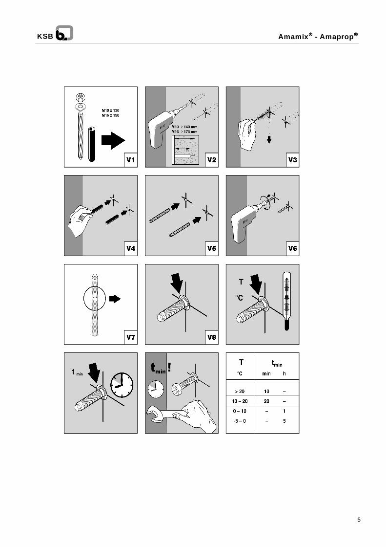
3.1 Composite Anchor Bolts
Technical data of stainless steel (VA) compositeanchor bolts
Anchor rod with external hexagon and placementtools
Article code(metric size of bolt)
Max. locking ∅ , da[mm]
M 10 x 130 30M 16 x 190 45
Mortar cartridge
Article code(material +metric size)
Nominal drill ∅ db[mm]
Depth of bore t[mm]
VA - M10 12 90VA � M 16 18 125
Nominal drill ø dB = 12 mm 18 mm
Depth of bore t = 90 mm 125 mm
Min. thickness ofconcrete wall
d = 140 mm 175 mm
Through-hole in thecomponent to befastened
11...12 mm 17.5...20 mm
Tightening torque 20 Nm 80 Nm
5
Amamix���� - Amaprop����KSB
6
Amamix���� - Amaprop����KSB
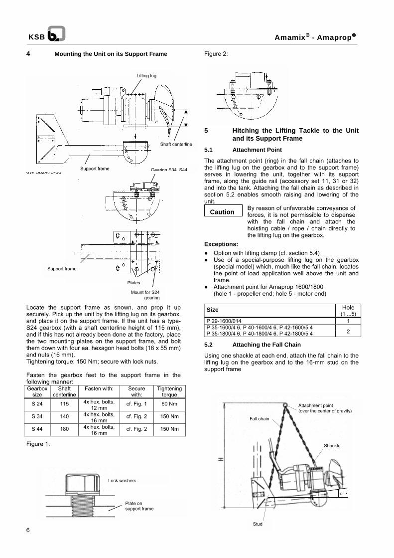
4 Mounting the Unit on its Support Frame
0
LsaSattaT
FfG
F
Figure 2:
Lifting lug
W 382473-00
ocate the suecurely. Pick und place it on24 gearbox (wnd if this has n
he two mountihem down withnd nuts (16 mmightening torqu
asten the geollowing manne
earboxsize
Shacenter
S 24 115
S 34 140
S 44 180
igure 1:
5 Hitching the Lifting Tackle to the Unitand its Support Frame
5.1 Attachment Point
The attachment point (ring) in the fall chain (attaches tothe lifting lug on the gearbox and to the support frame)serves in lowering the unit, together with its supportframe, along the guide rail (accessory set 11, 31 or 32)
Support fr
Support frame
Shaft centerline
pport frame as shown, and prop it upp the unit by the lifting lug on its gearbox,
the support frame. If the unit has a type-ith a shaft centerline height of 115 mm),ot already been done at the factory, place
ng plates on the support frame, and bolt four ea. hexagon head bolts (16 x 55 mm)
).e: 150 Nm; secure with lock nuts.
arbox feet to the support frame in ther:
ftline
Fasten with: Securewith:
Tighteningtorque
4x hex. bolts,12 mm
cf. Fig. 1 60 Nm
4x hex. bolts,16 mm
cf. Fig. 2 150 Nm
4x hex. bolts,16 mm
cf. Fig. 2 150 Nm
anseun
E●●
●
S
PPP
5.
Ulifsu
ame
s
Mount for S24gearing
Lock washers
Plate on support frame
d into the tank. Attaching the fall chain as described inction 5.2 enables smooth raising and lowering of theit.
Caution By reason of unfavorable conveyance offorces, it is not permissible to dispensewith the fall chain and attach thehoisting cable / rope / chain directly tothe lifting lug on the gearbox.
xceptions:Option with lifting clamp (cf. section 5.4)Use of a special-purpose lifting lug on the gearbox(special model) which, much like the fall chain, locatesthe point of load application well above the unit andframe.
PlateGearing S34, S44
Attachment point for Amaprop 1600/1800(hole 1 - propeller end; hole 5 - motor end)
ize Hole(1 ...5)
29-1600/014 1 35-1600/4 6, P 40-1600/4 6, P 42-1600/5 4 35-1800/4 6, P 40-1800/4 6, P 42-1800/5 4 2
2 Attaching the Fall Chain
sing one shackle at each end, attach the fall chain to theting lug on the gearbox and to the 16-mm stud on thepport frame
Fall chain
Attachment point(over the center of gravity)
Shackle
5° *
Stud

7
Amamix���� - Amaprop����KSB
Make the legs of the chain long enough to ensure that theattachment point is sufficiently high and that an inclinationof 5° (high end = propeller end) is maintained for easyraising and lowering of the unit with its support frame.This applies both to installation with the unit parallel to thesupport frame axis and to its installation with the propellerslanting downward. The Amaprop models 1600 and 1800must be installed horizontally.
The standard maximum length for a concomitantlysupplied KSB crane 4.6 and a railing height of 1.1 m is1.4 m. Please also read and heed the crane operatinginstructions!
Depending on the employed type of lifting gear and on theheight of the railing around the tank, the dimension H (cf.page 6) must be chosen such that the unit and supportframe will still pass over the railing when suspended onthe lifting gear in its uppermost working position.
Unneeded chain links (those outside ofthe taut length) should be removed tokeep them from rubbing on the unit or itssupport frame or interfering with thepropeller when the mixer is started!
5.3 Attaching the (Steel) Hoisting Cable, theHoisting Chain, or the (Polypropylene)Hoisting Rope
Depending on the chosen type of lifting tackle, use ashackle to attach the (steel) hoisting cable (for crane 4.6or 4.8 from the KSB scope of supply), the stainless steelhoisting chain, or the polypropylene hoisting rope to eitherthe attachment point on the fall chain or the special-purpose lifting lug on the gearbox (cf. item 5.1). In thecase of the PP rope, no shackle is needed, because therope loops into the ring on the fall chain.
5.4 Mounting the Lifting Clamp (Optional)
If the scope of supply includes a lifting clamp, attach oneend of it to the lifting lug and the other end to the supportframe (after removing the 16-mm stud) by slipping thewide fork of the clamp (leaving room for the cable)between the skirts of the support frame and installing thebolt with two lock nuts as shown below.Tightening torque for 16-mm bolt: 150 Nm.
To raise and lower the unit, attach the lifting hook to thehoisting cable / chain (depending on which type of liftinggear and tackle is used) with the aid of a shackle.
Lifting clamp
Ring inthe fallchain

8
Amamix���� - Amaprop����KSB
6 Attaching the Cable Harness to the Unit
Attach the cable harness to the motor housing as shownbelow. Slip the protective sleeve over the cable, slide it allthe way up to the stop on the cable connector, pull thethusly protected cable through the rings on the cableharness, and use four cable ties to fasten it securely tothe cable harness.
Motor: 01 4, 02 4, 03 4 Motor: 5 4...16 44 6...12 6
Protective sleeve
Cable tie
Cableharness
8x90-mmsocket headcap screw
A8.4 washer; 2x8-mm hexagonnuts (lock nuts)
Protectivesleeve
Cable tie
Cableharness
80x50-mmsocket headcap screw

0W 384 398--00
11 FÜV(optional)
11 OH
included in scope of supplyfor geared units
Support frame
Bracing
11 GR
Retaining bracket
B
A
Guide rail
B
L
S
200
6015
2500
2880
90�
1302
1627
2505 28
06
300
350
300
� 20
150
� 20
130
Dimensions S and L(cf. unit dimension tables)
A26
0
200
min
.120
100x100x5
192
Installation example:Fastened to the tank edge(optional)
Installation example:Installation either with composite anchor bolts(included in KSB scope of supply), or with 16-mm bolts(owner supply), depending on the structural geometry
350
+50
200
225
135
Extension(cf. item 7.3)
Baseplate
Retainingbracket
Retainingbracket
h2
h1
h min
Min. dimensions h, h1 and h2cf. section 8.5 table, page 16
Amamix�/Amaprop�
9
Standard Installation Accessories, Set No. 11
For stationary free-standing installation on level tank floorAmamix (gear unit) 500, 800;Amaprop 1000, 1200, 1600, 1800;optional for Amamix direct 215, 300, 400, 500, 600
Free-standing installation of the guide rail on the tank floor for mounting the mixer at a greater distance from the tank walls, uppermounting fixture optional.
10
Amamix���� - Amaprop����KSB
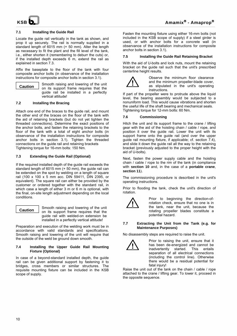
7.1 Installing the Guide Rail
Locate the guide rail vertically in the tank as shown, andprop it up securely. The rail is normally supplied in astandard length of 6015 mm (+ 50 mm). Alter the lengthas necessary to fit the plant and the fill level of the tank,i.e., either shorten it (remembering to deburr the cuts) or,if the installed depth exceeds 6 m, extend the rail asexplained in section 7.3.
Affix the baseplate to the floor of the tank with fourcomposite anchor bolts (in observance of the installationinstructions for composite anchor bolts in section 3.1).
Caution Smooth raising and lowering of the uniton its support frame requires that theguide rail be installed in a perfectlyvertical attitude!
7.2 Installing the Bracing
Attach one end of the braces to the guide rail, and mountthe other end of the braces on the floor of the tank withthe aid of retaining brackets (but do not yet tighten thethreaded connections). Determine the exact positions ofthe anchor bolts, and fasten the retaining brackets to thefloor of the tank with a total of eight anchor bolts (inobservance of the installation instructions for compositeanchor bolts in section 3.1). Tighten the threadedconnections on the guide rail and retaining bracketsTightening torque for 16-mm bolts: 150 Nm.
7.3 Extending the Guide Rail (Optional)
If the required installed depth of the guide rail exceeds thestandard length of 6015 mm (+ 50 mm), the guide rail canbe extended on the spot by welding on a length of squarerail (100 x 100 x 5 mm acc. DIN 59411, DIN 2395, orequivalent). The square rail can either be provided by thecustomer or ordered together with the standard rail, inwhich case a length of either 3 m or 6 m is optional, withthe final, on-site length adjustment depending on the localconditions.
Caution Smooth raising and lowering of the uniton its support frame requires that theguide rail with welded-on extension beinstalled in a perfectly vertical attitude!
Preparation and execution of the welding work must be inaccordance with valid standards and specifications.Smooth raising and lowering of the unit will require thatthe outside of the weld be ground down smooth.
7.4 Installing the Upper Guide Rail MountingFixture (Optional)
In case of a beyond-standard installed depth, the guiderail can be given additional support by fastening it tobridges, cross members or similar structures. Therequisite mounting fixture can be included in the KSBscope of supply.
Fasten the mounting fixture using either 16-mm bolts (notincluded in the KSB scope of supply) if a steel girder isused, or with anchor bolts for a concrete wall (inobservance of the installation instructions for compositeanchor bolts in section 3.1).
7.5 Installing the Guide Rail Retaining Bracket
With the aid of U-bolts and lock nuts, mount the retainingbracket on the guide rail such that the unit's prescribedcenterline height results.
Observe the minimum floor clearanceand the minimum propeller-blade cover,as stipulated in the unit's operatinginstructions.
If part of the propeller were to protrude above the liquidlevel, the bearing assembly would be subjected to anonuniform load. This would cause vibrations and shortenthe useful life of the shaft bearing and mechanical seals.Tightening torque for 12-mm bolts: 60 Nm.
7.6 Commissioning
Hitch the unit and its support frame to the crane / liftinggear with the aid of the hoisting chain / cable / rope, andposition it over the guide rail. Lower the unit with itssupport frame onto the guide rail (and over the upperguide rail mounting fixture, if applicable; cf. section 7.4),and slide it down the guide rail all the way to the retainingbracket (previously adjusted to the proper height with theaid of U-bolts).
Next, fasten the power supply cable and the hoistingchain / cable / rope to the rim of the tank (in compliancewith section 10 and, in the case of a portable crane,section 11).
The commissioning procedure is described in the unit'soperating instructions.
Prior to flooding the tank, check the unit's direction ofrotation.
Prior to beginning the direction-of-rotation check, ensure that no one is inthe tank, near the unit, because therotating propeller blades constitute apotential hazard.
7.7 Extracting the Unit from the Tank (e.g. forMaintenance Purposes)
No disassembly steps are required to raise the unit.
Prior to raising the unit, ensure that ithas been de-energized and cannot beinadvertently started. This entailsseparation of all electrical connections(including the control line). Otherwisethere would be a residual potential forfatal injury!
Raise the unit out of the tank on the chain / cable / ropeattached to the crane / lifting gear. To lower it, proceed inthe opposite sequence.

min
.
0W 384 400--00
200
(260)
(200)
120
Installation example:Fastened to the tank edge
Installation example:Horizontal tank floor
31 VKR
Square guide rail100x100x5 DIN 59411
200
B
A
Max
.ins
talle
dde
pth:
6m
(>6
m:c
ente
rsu
ppor
trec
omm
ende
dfo
rgu
iede
rail)
200
31 GR
C
included in scope of supplyfor geared units
Retaining bracketSupport frame
135
192
A B
C
150
150
200
200
L
SDimensions L and Scf. unit dimensiontables
Mountingfixture
h2
h 1h min
Min. dimensions h, h1 and h2cf. section 8.5 table, page 16
Amamix�/Amaprop�
11
8 Standard Installation Accessories, Set No. 31
For stationary, vertically adjustable installation of mixer, without horizontal swivelling optionAmamix (geared) 500, 800;Amaprop 1000, 1200, 1600, 1800;optional for Amamix direct 215, 300, 400, 500, 600

0W 384 400--00
Installation example:Upper mounting fixture attached to rim of tank with the aidof a bracket (jet direction not pre-set)
D D48
1
418
200
200
273
31 KBR
202
74
230
200
Installation example:Center guide rail mounting fixture, 100x100x5 mm
Welded connection to guide rail Version with flexible fitting
Installation example:Floor bracket for the lower mounting fixture;inclines from 0o ... 90o
Installation example:Lower mounting fixture attached to wall of tank ona bracket
Jet pre-set10o to the right
Jet direction of submersible motormixer can be set in stages of 9o toeach side(maximum angle: 45o)
Installation exampleUpper mounting fixture attached to edge of tank with the aid of abracket jet direction not pre-set))
Fasten with either composite anchor boltsfrom the KSB scope of supply (min. con-crete grade: B25) or 16-mm-bolts, de-pending on the local situation.
200
H
H
222
Version without pre-setting
120
200
120
200
400
241
241
481
min
.16
5
E
E
F
F
200
G G
G
150
150
200
200200
31 SBB/UWB
31 SBB/UWB
120
31 KBR
Shorten fixture to required length (dependent on local situation),and weld it to the guide rail
Guide rail 100x100x5 mm
31 MIAS -- SW 31 MIAS -- ST
(cannot be used with 31 KBR as pre-setting device)
Supplied lengt210 mm
Square rail100x100x5 mm
Amamix�/Amaprop�
12
Standard Installation Accessories, Set No. 31
For stationary, vertically adjustable installation of the mixer, without horizontal swivelling optionAmamix (gearing) 500, 800;Amaprop 1000, 1200, 1600, 1800;optional for Amamix direct 215, 300, 400, 500, 600

Amamix���� - Amaprop����KSB
8 Mounting Accessories 318.1 Installing the Upper Guide Rail Mounting
Fixture
Fasten the mounting fixture to the wall of the tank with twoanchor bolts (taking into account the adjusting range ofthe slotted holes and working in observance of theinstallation instructions for composite anchor bolts insection 3.1). Do not yet tighten the bolts.
A minimum clearance of 120 mm mustbe maintained between the fixture andthe top edge of the tank wall.
With the aid of a plumb line, determine the centerline ofthe still-to-be-installed guide rail and, hence, the centerpoint of the baseplate. Mark out the latter.
Installation example:Mounting on edge of tank
With the aid of a plumb line, determine the centerline ofthe still-to-be-installed guide rail and, hence, the centerpoint of the baseplate. Mark out the latter.
0W 384400-00
Fastening the upper mounting fixture to the wall ofthe tank (with jet direction pre-set)
Plumb
Bracket
A
Upper mounting fixture
13
0W 384400-00
Distinctive features of optional installation methods:
- Fastening the upper mounting fixture to the rim ofthe tank (jet direction not pre-set)
Loosely install the fixture plus bracket with two 16x55-mmhexagon head bolts. Determine the exact proper positionof the bracket on the rim of the tank. If the tank has nosolid rim, note that the minimum acceptable thickness ofthe concrete wall is 175 mm. Mark out the mountingholes, drill the dowel holes, and install the anchor bolts onthe rim of the tank (in observance of the installationinstructions for composite anchor bolts in section 3.1).
Using two 16 x 55-mm hexagon head bolts, install themounting fixture plus bracket such that the jet is pointingin the desired direction (swivels 45° to either side, in 9°increments). Tightening torque for 16-mm bolts: 150 Nm.Secure with lock nuts. If the tank has no solid rim, notethat the minimum acceptable thickness of the concretewall is 175 mm. Mark out the mounting holes, drill thedowel holes, and install the anchor bolts on the wall of thetank, but do not yet torque the bolts (in observance of theinstallation instructions for composite anchor bolts insection 3.1).
With the aid of a plumb line, determine the centerline ofthe still-to-be-installed guide rail and, hence, the centerpoint of the baseplate. Mark out the latter.
Installation example:
Fastening the upper mounting fixture plus bracket tothe edge of the tank (with jet direction pre-set)
PlumbBracket
200
400
F
(260)
(200)
Plumb
B
200
Minimum thickness ofconcrete wall: 175 mm!

14
Amamix���� - Amaprop����KSB
8.2 Installing the Lower Guide Rail MountingFixture
- Installing the baseplate on a level floor
Mark out the mounting holes with respect to the centerlineof the guide rail. Drill dowel holes, and fasten the anchorbolts to the floor of the tank (in observance of theinstallation instructions for composite anchor bolts insection 3.1).
Place the baseplate along with the lower guide railmounting fixture over the anchor bolts, and tighten thebolts to the prescribed torque.
Installation example:
Horizontal tank floor
0W 384400-00
Distinctive features of optional methods ofinstallation:
- Installing the lower guide rail mounting fixture onan inclined floor or on a wall-mounted bracket
Fasten the bracket and plate in place with four ea. 16 x55-mm hexagon head bolts, tightening to a torque of 150Nm. Secure with lock nuts. In case of an inclined floor,adjust the bracket / plate as necessary beforehand.
Mount the baseplate and lower guide rail mounting fixtureon the floor slab, and fasten with four each 15 x 55-mmhexagon head bolts.
With the aid of a plumb line suspended from the upperguide rail mounting fixture, determine the location of thelower bracket for mounting on the wall or on the inclinedfloor. Mark out the points of fixation, drill the dowel holes,and fasten the anchor bolts to the wall or floor, asapplicable (in observance of the installationinstructions for composite anchor bolts in section3.1). Place the preassembled bracket with baseplate andlower guide rail mounting fixture over the anchor bolts,and tighten to the prescribed torque. Tighten themounting bolts on the baseplate / bracket (16-mm bolts:150 Nm).
Installation example:
Wall-mounting the lower guide rail mounting fixtureplus bracket(not applicable to bracket with pre-set jet direction)
0W 384400-00
Installation example:
Bracket for installing the lower guide rail mountingfixture on an inclined floor (0°...90°)
Define the length of the guide rail, and install the guiderail and the upper mounting fixture in analogy to thefollowing description.
8.3 Installing the Guide Rail
- Cutting the guide rail to length
The guide rail consists of a square rail in accordance withDIN 59411 with the cross-sectional dimensions100 x 100 x 5 mm, for all model sizes..To determine the proper length, place the rail on the lowermounting fixture / baseplate, and align it vertically. Markout the proper length of rail on the upper mounting fixturesuch that the collar of the flexible fitting on the uppermounting fixture protrudes out of the rail. Cut the guiderail to length, cutting at right angles to the centerline, anddeburr the cut.
120
200
BaseplateVersion without pre-set jetdirection
222
Bracket
Baseplate

15
Amamix���� - Amaprop����KSB
- Installing the guide rail and upper mounting fixture
Place the guide rail on the lower baseplate mount, andalign it vertically. Insert the upper mounting fixture withflexible fitting into the guide rail, and fasten it to the wall ofthe tank with anchor bolts (in observance of theinstallation instructions for composite anchor bolts insection 3.1). Proceed analogously for the mountingoptions described in section 8.1.
Verify that the guide rail is vertical - as required forsmooth lowering of the unit along the rail!
If the rail is being held in place with a bracket on the rimof the tank, fasten the upper mounting fixture to thebracket with the hexagon head bolts (torque for 16-mmbolts: 150 Nm), and secure with locknuts. Check thevertical attitude of the guide rail - as required for smoothlowering of the unit along the rail!
- Greater installed depths and center guide railmounting fixture
For any guide-rail length in excess of 6 meters, it isrecommended that a center guide rail mounting fixture beinstalled. In this case, define the length of the lower guiderail segment such that the center support is situatedabove the unit on its mounting fixture.
Depending on the chosen form of center support, it canbe inserted into the upper and lower guide rail segments*)with flexible fittings or, in the case of the welded version,welded onto the guide rail (cut to length).
Install the lower guide rail segment as indicated. Fastenthe center support to the wall with anchor bolts.
Verify the vertical attitude of the guide rail � as necessaryfor smooth lowering of the unit along the rail!
*) general scope of supply:upper guide rail segment without collarlower guide rail segment with collar
Version with welded connection to guide railShortened to size in accordance with local structuralgeometry, and welded to guide rail.
0W 384400-00
Version with flexible fitting
Center-support
200
Length supplied 210
G

16
Amamix���� - Amaprop����KSB
8.4 Extending the Guide Rail (Optional)
In case of a required installed depth for which thestandard-length guide rail from the normal scope ofsupply (4.25 m) would not suffice, it will be necessary toextend the guide rail on the spot by welding on anappropriate length of square rail measuring 100 x 100 x 5mm in accordance with DIN 59411, DIN 2395 orequivalent. The square rail can be provided either by thecustomer or purchased along with the rest of the orderfrom KSB in a length of 3 m or 6 m. Those lengths canthen be adjusted as necessary on site.
Caution Smooth raising and lowering of the uniton its support frame requires that theguide rail be installed in a perfectlyvertical attitude!
8.5 Installing the Guide Rail Retaining Bracket
With the aid of U-bolts and lock nuts, mount the retainingbracket on the guide rail such that the unit's prescribedcenterline height results.
Observe the minimum floor clearanceand the minimum propeller-blade cover,as stipulated in the unit's operatinginstructions.
If part of the propeller were to protrude above the liquidlevel, the bearing assembly would be subjected to anonuniform load. This would cause vibrations and shortenthe useful life of the shaft bearing and mechanical seals.Tightening torque for 12-mm bolts: 60 Nm.
Propeller Ø Gearboxcenterline
height
h1 min h2 min x (Propellercenter to
support-framemount)
Min. clearance:propeller
center/floor
[mm] [mm] [mm] [mm] [mm] [mm]
115 265140 290 500500180
250 900330
115 265140 400 1100 290 800800180 330
140 400 1150 290 9001000
140 400 1200 290 10001200
180 500 1200 310 13001600
180 500 1300 310 14001800
Retaining bracket
h min
0W 384400-00
hmin (top ofretaining
bracket tofloor)[mm]
235210170535510470
510
710
990
1090

17
Amamix���� - Amaprop����KSB
8.6 Mounting the Unit on the Guide Rail, incl.Definition and Lock-in of the Jet Direction
Attach the unit with support frame to the hoisting chain /cable / rope on the crane / lifting gear, and position it overthe guide rail. Slide it down over the upper mountingfixture and along the guide rail to stop at the retainingbracket (held in place by U-bolts at the proper height).
If the mounting fixture is attached directly to the wall of thetank or if retaining brackets are used, the jet direction iseither fixed or can be preset. Once the installation iscomplete, the jet direction can no longer be altered(unless the tank is emptied and the lower mountrepositioned). Mounting accessory 32 is recommended foruse in such cases.Next, fasten the power supply cable and the hoistingchain / cable / rope to the edge of the tank (taking care tocomply with section 10 and, in the case of a portablecrane, section 11).
8.7 Commissioning
The commissioning procedure is described in the unit'soperating instructions.
Prior to flooding the tank, check the unit's direction ofrotation.
Prior to beginning the direction-of-rotation check, ensure that no one is inthe tank, near the unit, because therotating propeller blades constitute apotential hazard.
8.8 Extracting the Unit from the Tank(e.g. for Maintenance Purposes)
No disassembly steps are required to raise the unit.
Prior to raising the unit, ensure that ithas been de-energized and cannot beinadvertently started. This entailsseparation of all electrical connections(including the control line). Otherwisethere would be a residual potential forfatal injury!
Raise the unit out of the tank on the chain / cable / ropeattached to the crane / lifting gear. To lower it, proceed inthe opposite sequence.

0W 384 399--00
(260)
(200)
Installation example:Mounted on the tank edge
Installation example:Horizontal tank floor
32 FÜH(32 FÜV)
Square guide rail100x100x5 DIN 59411
250
B
A
Max
.ins
talla
tion
dept
h6
m(>
6m
cent
ersu
ppor
trec
omm
ende
dfo
rgu
ide
rail
32 GR
(included in scope ofsupply for geard units)
Support frameRetaining bracket
135
192
A B
C
150
150
200
200
min
.12
0
150
C
150
Installation example:Mixer set to 45o swivel angle
L
SDimensions L and S:cf. unit dimensiontables
Min. dimensions h, h1 and h2cf. section 8.5 table, page 16
Amamix�/Amaprop�
18
9 Standard Installation Accessories, Set No. 32
For stationary, vertically adjustable installation of mixer, with horizontal swivelling optionAmamix (geared) 500, 800;Amaprop 1000, 1200, 1600, 1800;optional for Amamix direct 215, 300, 400, 500, 600

0W 384 399--00
Installation example:Upper mounting fixture attached to the rim of the tank with theaid of a bracket
Installation example:Center guide rail mounting fixture, 100x100x5 mm
Installation example:Bracket for attaching the lower mounting fixtureto an inclined floor 0o ... 90o
Installation example:Lower mounting fixture attached to wall of tankon a bracket
Fasten with either composite an-chor bolts from the KSB scopeof supply (min. concrete grade:B25) or with 16-mm bolts, de-pending on the local situation
F
F
150
150
200
20032 MIAS
32 SBB/UWB
32 SBB/UWB
E
Installation example:Mixer set at 45o swivel angle
D
D
32 KBR
E
250
74
202
250
273
230
200
418
200
150
150
222
150
120
Range of adjustment:240 ... 260 mm
Amamix�/Amaprop�
19
Standard Installation Accessories, Set No. 32
For stationary, vertically adjustable installation of mixer, with horizontal swivelling optionAmamix (geared) 500, 800;Amaprop 1000, 1200, 1600, 1800;optional for Amamix direct 215, 300, 400, 500, 600

20
Amamix���� - Amaprop����KSB
Installing the Upper Guide Rail Mounting Fixture
- Fastening the upper mounting fixture to the wallof the tank
Fasten the mounting fixture to the wall of the tank with twoanchor bolts (taking into account the adjusting range ofthe slotted holes and working in observance of theinstallation instructions for composite anchor bolts insection 3.1). Do not yet tighten the bolts.
A minimum clearance of 120 mm mustbe maintained between the fixture andthe top edge of the tank wall.
With the aid of a plumb line, determine and mark out thecenter point of the baseplate mount in relation to theswivel point of the upper mounting fixture. Keep in mindthat the swivel axis does not coincide with the centerlineof the guide rail.Installation example:Mounting on edge of tank
0W 384399-00Installation example::Mixer set to 45° swivel angle
Distinctive- Fasteninthe tankLoosely inshexagon hof the bracsolid rim, nthe concreholes, drill the rim ofinstructionsWith the acenter poiswivel pointhat the swof the guid
Installation example:
Fastening the upper mounting fixture plus bracket tothe edge of the tank
Installation example:Mixer set to 45° swivel angle
0W 384399-00
9.2 Installing the Lower Guide Rail MountingFixture
- Installing the baseplate on a level floor
Mark out the mounting holes with respect to the centerlineB
Swivel axis
Plumb
Upper mountingfixture
Min. thicknessof concrete wall:175 mm!
Plumb
Swivel axis
Bracket
A
features of optional installation methodsg the upper mounting fixture to the rim of
tall the fixture plus bracket with two 16x55-mmead bolts. Determine the exact proper positionket on the rim of the tank. If the tank has noote that the minimum acceptable thickness ofte wall is 175 mm. Mark out the mountingthe dowel holes, and install the anchor bolts on the tank (in observance of the installation for composite anchor bolts in section 3.1).
id of a plumb line, determine and mark out thent of the baseplate mount in relation to thet of the upper mounting fixture. Keep in mindivel axis does not coincide with the centerline
e rail.
of the guide rail. Drill dowel holes, and fasten the anchorbolts to the floor of the tank (in observance of theinstallation instructions for composite anchor bolts insection 3.1).
Place the baseplate along with the lower guide railmounting fixture over the anchor bolts, and tighten thebolts to the prescribed torque (section 3.1).
Installation example:Horizontal tank floor
(260)
(200)

21
Amamix���� - Amaprop����KSB
Distinctive features of optional methods ofinstallation:
Installing the lower guide rail mounting fixture on aninclined floor or on a wall-mounted bracket
Fasten the bracket and plate in place with four ea. 16 x55-mm hexagon head bolts, tightening to a torque of 150Nm. Secure with lock nuts. In case of an inclined floor,adjust the bracket / plate as necessary beforehand.
Mount the baseplate and lower guide rail mounting fixtureon the floor slab, and fasten with four each 16 x 55-mmhexagon head bolts.
With the aid of a plumb line suspended from the upperguide rail mounting fixture, determine the location of thelower bracket for mounting on the wall or on the inclinedfloor. Mark out the points of fixation, drill the dowel holes,and fasten the anchor bolts to the wall or floor, asapplicable (in observance of the installation instructionsfor composite anchor bolts in section 3.1). Position thepreassembled bracket with lower swivel point for theguide rail on the composite anchor bolts, and tighten tothe prescribed torque.
Define the length of the guide rail, and install the guiderail and the upper mounting fixture in analogy to thefollowing description.
Installation example:
Installation of the lower mounting fixture on a wall-mounted bracket
0W 384399-00
Installation example:
Bracket for installing the lower guide rail mountingfixture on an inclined floor (0°...90°)
0W 384399-00
9.3 Installing the Guide Rail
- Cutting the guide rail to length
Position the guide rail in the tank, as shown, in a verticalattitude. The standard supplied length is 4.25 m. Theguide rail is a welded construction made of square rail inaccordance with DIN 59411, with the cross-sectionaldimensions 100 x 100 x 5 for all unit sizes.
Depending on the local situation (unit model, tank filllevel, ...) adjust the length of the rail as necessary, i.e.,either shorten it (remembering to deburr the cut) or bylengthening it if the installed depth exceeds 4.25 m (heedsection 9.4).
To determine the proper length, place the rail on the lowermounting fixture / baseplate, and align it vertically. Markout the proper length of rail on the upper mounting fixturesuch that the collar of the flexible fitting on the uppermounting fixture protrudes out of the rail. Cut the guiderail to length, cutting at right angles to the centerline, anddeburr the cut.
0W 384399-00
- Installing the guide rail and upper mounting fixture
Place the guide rail on the lower baseplate mount, andalign it vertically. Insert the upper mounting fixture withflexible fitting into the guide rail, and fasten it to the wall ofthe tank with anchor bolts (in observance of theinstallation instructions for composite anchor bolts insection 3.1). Secure the threaded connection with locknuts. Tighten the 16-mm bolts to a torque of 150 Nm.
Proceed analogously for the mounting options describedin section 9.1
Verify that the guide rail is vertical - as required forsmooth lowering of the unit along the rail!
Bracket Plate
Lowermountingfixture

2
Amamix���� - Amaprop����KSB
- Greater installed depths and center guide railmounting fixture
For any guide-rail length in excess of 6 meters, it isrecommended that a center guide rail mounting fixture beinstalled. In this case, define the length of the lower guiderail segment such that the center support is situatedabove the unit on its mounting fixture.
Optionally, the center support can be welded to the guiderail (standard supplied length of 4.25 m, plus the guide railextension welded on in accordance with section 9.4), orbolted onto both guide-rail segments (tightening torque for12-mm bolts: 60 Nm).
Fasten the center support to the wall with compositeanchor bolts (in observance of the installation instructionsfor composite anchor bolts in section 3.1).
Verify that the guide rail is vertical � as required forsmooth lowering of the unit along the rail! Slotted holesare provided for infinite adjustment of the wall clearancewith the aid of 12-mm nuts and bolts.
Tightening torque for 12-mm bolts: 60 Nm.
9.4 Extending the Guide Rail (Optional))
In case of a required installed depth for which thestandard-length guide rail from the normal scope ofsupply (4.25 m) would not suffice, it will be necessary toextend the guide rail on the spot by welding on anappropriate length of square rail measuring 100 x 100 x 5mm in accordance with DIN 59411, DIN 2395 orequivalent. The square rail can be provided either by thecustomer or purchased along with the rest of the orderfrom KSB in a length of 3 m or 6 m. Those lengths canthen be adjusted as necessary on site.
Caution Smooth raising and lowering of the uniton its support frame requires that theguide rail be installed in a perfectlyvertical attitude!
9.5 Installing the Guide Rail Retaining Bracket
With the aid of U-bolts and lock nuts, mount the retainingbracket on the guide rail such that the unit's prescribedcenterline height results.
Observe the minimum floor clearanceand the minimum propeller-blade cover,as stipulated in the unit's operatinginstructions.
If part of the propeller were to protrude above the liquidlevel, the bearing assembly would be subjected to anonuniform load. This would cause vibrations and shortenthe useful life of the shaft bearing and mechanical seals.
2
Tightening torque for 12-mm bolts: 60 Nm.
Min
. 500
mm
250
0W 384399-00
Adjust the retaining bracket in analogy to section 8.5. Thenear-floor guide rail configuration results in a somewhatlonger installed height for propellers of smaller diameter
Support frame
Range of adjustment for the above dimension250: 240...260.On-site welding of guide rail segments; grindweld down smooth (to facilitate smooth raisingand lowering of the support frame).
Retainingbracket
375
h min
200

Amamix���� - Amaprop����KSB
9.6 Mounting the Unit on the Guide Rail, incl.Definition and Lock-in of the Jet Direction
Attach the unit with support frame to the hoisting chain /cable / rope on the crane / lifting gear, and position it overthe guide rail. Slide it down over the upper mountingfixture and along the guide rail to stop at the retainingbracket (held in place by U-bolts at the proper height).
The jet direction can be altered by using the adjusting armto rotate the guide rail around the swivel axis of the uppermounting fixture. It is advisable to set the jet directionduring installation of the upper mounting fixture (= easilyaccessible).Subsequent alteration of the jet direction would requireshutting down the mixer.
Prior to making the adjustment, ensure thatit has been de-energized and cannot beinadvertently started. This entailsseparation of all electrical connections(including the control line). Otherwise therewould be a residual potential for fatalinjury!
Remove the 10-mm locking screws, and adjust the jetdirection through one of the 30-mm adjusting holes (coverplate raised). Lock in the adjustment with screws betweenthe adjusting arm and the mounting plate.Tightening torque for 10-mm screws: 35 Nm; secure withlock nuts.
Nechcocr
9.7 Commissioning
The commissioning procedure is described in the unit'soperating instructionsPrior to flooding the tank, check the unit's direction ofrotation.
Prior to beginning the direction-of-rotation check, ensure that no one is inthe tank, near the unit, because therotating propeller blades constitute apotential hazard.
9.8 Extracting the Unit from the Tank(e.g. for Maintenance Purposes)
No disassembly steps are required to raise the unit,independent of the set jet direction.
Prior to raising the unit, ensure that it hasbeen de-energized and cannot beinadvertently started. This entailsseparation of all electrical connections(including the control line). Otherwise therewould be a residual potential for fatalinjury!
Raise the unit out of the tank on the chain / cable / ropeattached to the crane / lifting gear. To lower it, proceed inthe opposite sequence.
10 Fastening the Power Supply Cable and theHoisting Chain / Cable / Rope
10.1 Fastening and Guying the Power SupplyCable
Slip the cable support sleeve over the end of the cable,and pull up the cable. Use the factory-supplied shackle to
A
10-mm lockingscrew
23
xt, fasten the power supply cable and the hoistingain / cable / rope to the edge of the tank (taking care tomply with section 10 and, in the case of a portableane, section 11).
affix the cable support sleeve at the proper point at theedge of the tank, e.g., either the adjusting arm or thebracket on the rim of the tank. Be careful not to produceany fraying points along the cable. (Pad the rim of thetank, if necessary.)
Electric cables routed with too much slackare susceptible to damage caused eitherby constant flow-induced motion or by therotating propeller blades.
0W 384 456-00
Adjusting armMounting plate

24
Amamix���� - Amaprop����KSB
Power supply cable
Cable support sleevewith eyelet
0W 384 456-00
10.2 Fastening the Hoisting Chain / Cable / Rope
With the mixer in its normal workingposition, the hoisting chain / cable / ropeshould be unstressed, but withoutexcessive sag. A chain / cable / ropewith too much sag would be susceptibleto damage caused either by constantflow-induced motion or by the rotatingpropeller blades.
The same applies to the chain / cable / rope on block &cable lifting gear / cranes.
Shackle the chain / cable / rope to an appropriate point,e.g., the adjusting arm, the railing, or the bracket on therim of the tank; take care not to produce any frayingpoints, i.e., pad the edge of the tank as necessary.
11 Installing / Handling the Lifting Gear(Crane)
If the scope of supply includes a crane, the accompanyingset of crane operating instructions must be followed forinstalling the holders on the wall or rim of the tank.
KSB designation Haacon designation
Crane 4.6 Type 4551- 0,36
4751 - 0,36
Crane 4.8 Type 64604 - 207 134
11.1 Installing the Rope Tensioner / Bollard
After the unit has been lowered into the tank, remove the5-mm steel cable from the winch of the lifting gear (in thecase of a portable crane, type 4.6 or 4.8, belonging to theKSB scope of supply), wrap the entire length of cablearound the rope tensioner / bollard mounted beside thetank, and leave it there for the next time it is needed.
This, of course, first requires that the rope tensioner /bollard be installed beside the tank (perhaps below therailing) and secured with composite anchor bolts (inobservance of the installation instructions for compositeanchor bolts in section 3.1).
Insert one end of the steel cable through the U-bolt on therope tensioner, pull it all the way through, and secure bytightening the 5-mm U-bolt to a torque of 7 Nm.Wind the cable around the two sheet metal retainingbrackets. Use the second U-bolt to keep the end of thecable from unwinding inadvertently. Tighten the 5-mm U-bolt to a torque of 7 Nm.
With the mixer in its normal operatingposition, the hoisting chain / cable / ropemust be unstressed, but without toomuch slack. Excessive slack couldcause the chain / cable / rope to getcaught in the rotating blades of thepropeller. Take care to ensure that nokinks occur in the chain / cable / rope..
Alternatively, the rope tensioner / bollard could bemounted directly on the railing.
SP

1. Serial No.
KRT-F 100-250/7 4 UG-2492--M01--753328
enter here
2. the required part with part no.
enterhere
Sample
. . . and should something have to be replaced,
the competent Spare Parts Service of KSB is at your disposal for the products
! Amarex/KRT ! Amamix/Amaprop! Sewatec ! Wirbeljet! Amacan ! Getec! Omega
To: KSB Aktiengesellschaft Postfach 200743 Date:Turmstr. 92 D-06008 Halle/SaaleD-06110 Halle/SaaleErsatzteilabteilung
Fax: (+49) 345/48 26 4691 Tel: (+49) 345/48 26--0
From:
In order to guarantee a smooth handling of your spare parts inquiry, we request that you let us have the following data:
! this you find on the name plateof your pumpe.g. 2--M01--753328
or29140346
in addition:
Pump typee.g. KRT-F 100-250/7 4 UG-249
! you will find the description of the partsin the operating instructionse.g. Impeller, Part no. 230
in addition:
for multi--vane impeller:impeller diameter in mm
for terminal gland:cable length in mm

26
Amamix���� - Amaprop����KSB
1592
.811
-10
12/2
000
Subj
ect t
o te
chni
cal m
odifi
catio
n
KSB AktiengesellschaftIndustry and Water Engineering Pumps DivisionP.O. Box 200743, D-06008 Halle (Saale) � Turmstraße 92, D-06110 Halle (Saale)Tel. (+49) 3 45 48 26-0 � Fax (+49) 3 45 48 26 46 99 � www.ksb-industry.comKSB