Embed Size (px)
Citation preview

18 INCH TRENCHER ASSEMBLY GUIDEMODEL: OPT11818 INCH TRENCHER
DK2 POWER USA
4301 S Valley View Blvd STE 10-11Las Vegas, NV [email protected] 8-4 M-F
18 IN CUTTING DEPTHAUTO DRIVE AUGERKOHLER ENGINE
18 INCH TRENCHER – KOHLER 7HP
REV 1 – 3-2-19
OPT118
STEP 1:
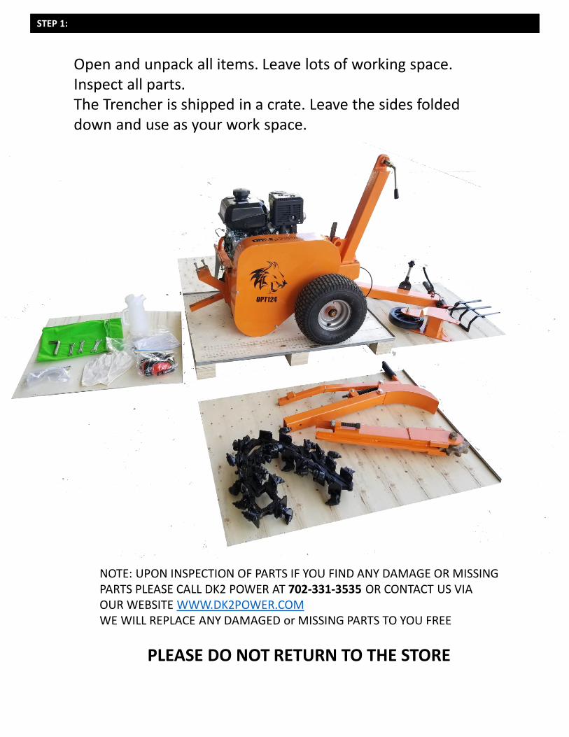
Open and unpack all items. Leave lots of working space. Inspect all parts.The Trencher is shipped in a crate. Leave the sides folded down and use as your work space.
NOTE: UPON INSPECTION OF PARTS IF YOU FIND ANY DAMAGE OR MISSING PARTS PLEASE CALL DK2 POWER AT 702-331-3535 OR CONTACT US VIA OUR WEBSITE WWW.DK2POWER.COMWE WILL REPLACE ANY DAMAGED or MISSING PARTS TO YOU FREE
PLEASE DO NOT RETURN TO THE STORE
STEP 2:
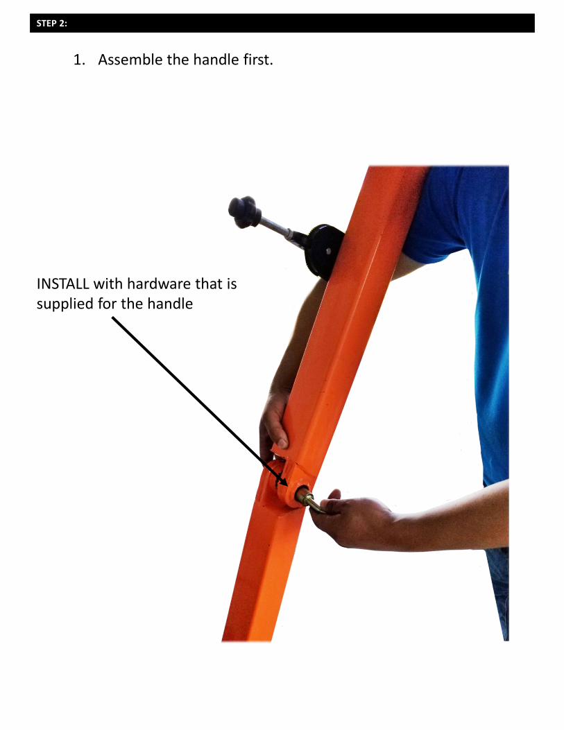
1. Assemble the handle first.
INSTALL with hardware that is supplied for the handle
STEP 3:
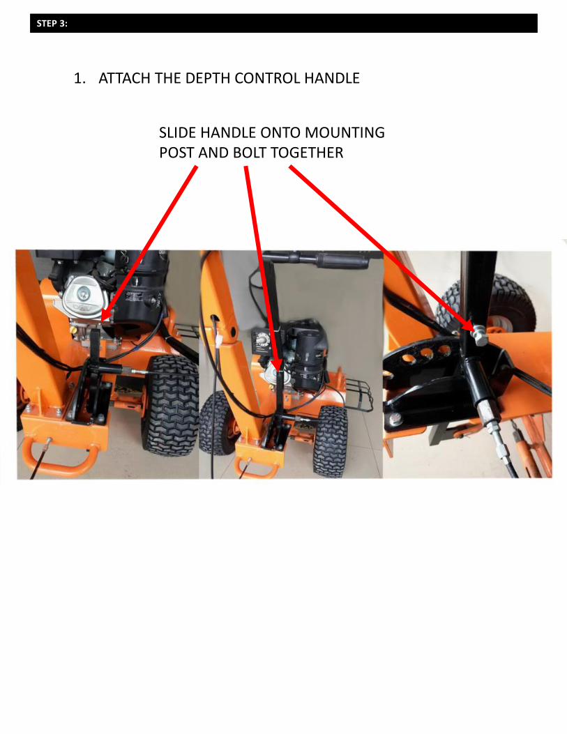
1. ATTACH THE DEPTH CONTROL HANDLE
SLIDE HANDLE ONTO MOUNTING POST AND BOLT TOGETHER
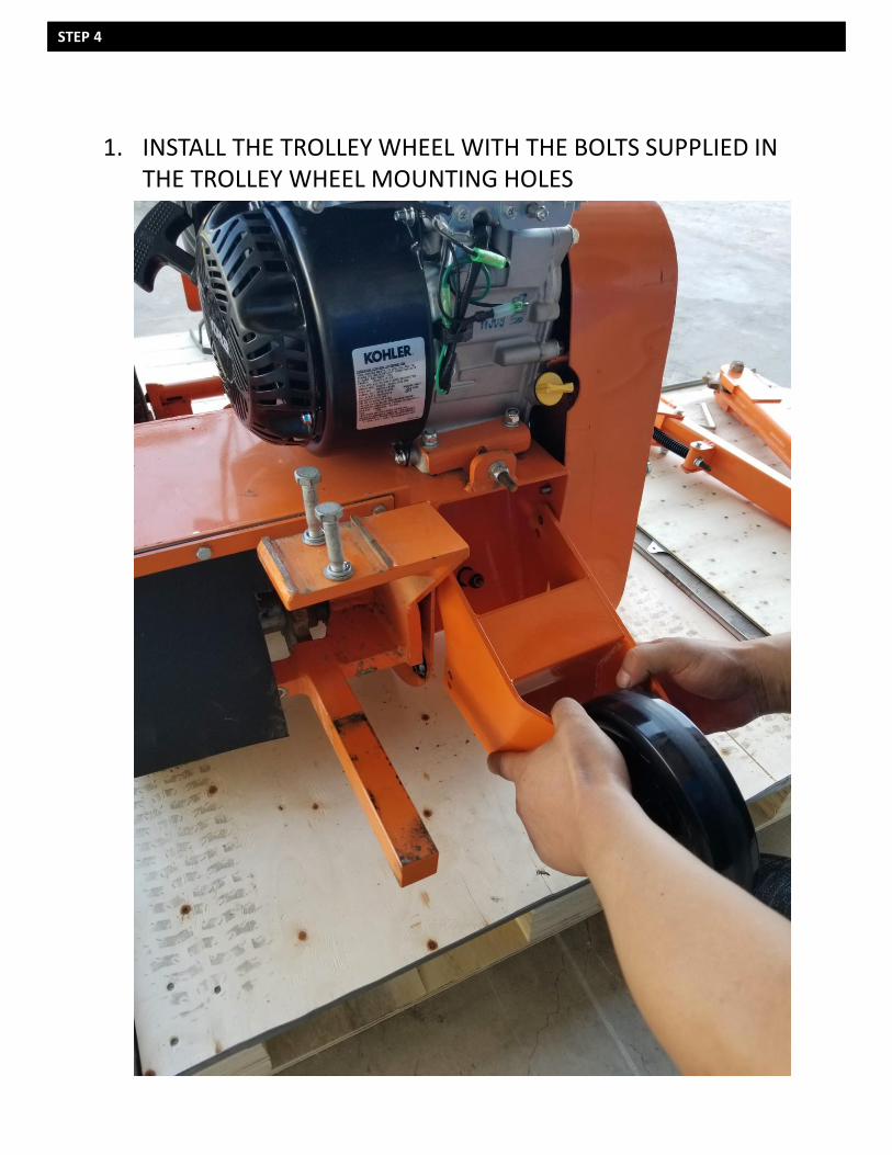
STEP 4
1. INSTALL THE TROLLEY WHEEL WITH THE BOLTS SUPPLIED IN THE TROLLEY WHEEL MOUNTING HOLES
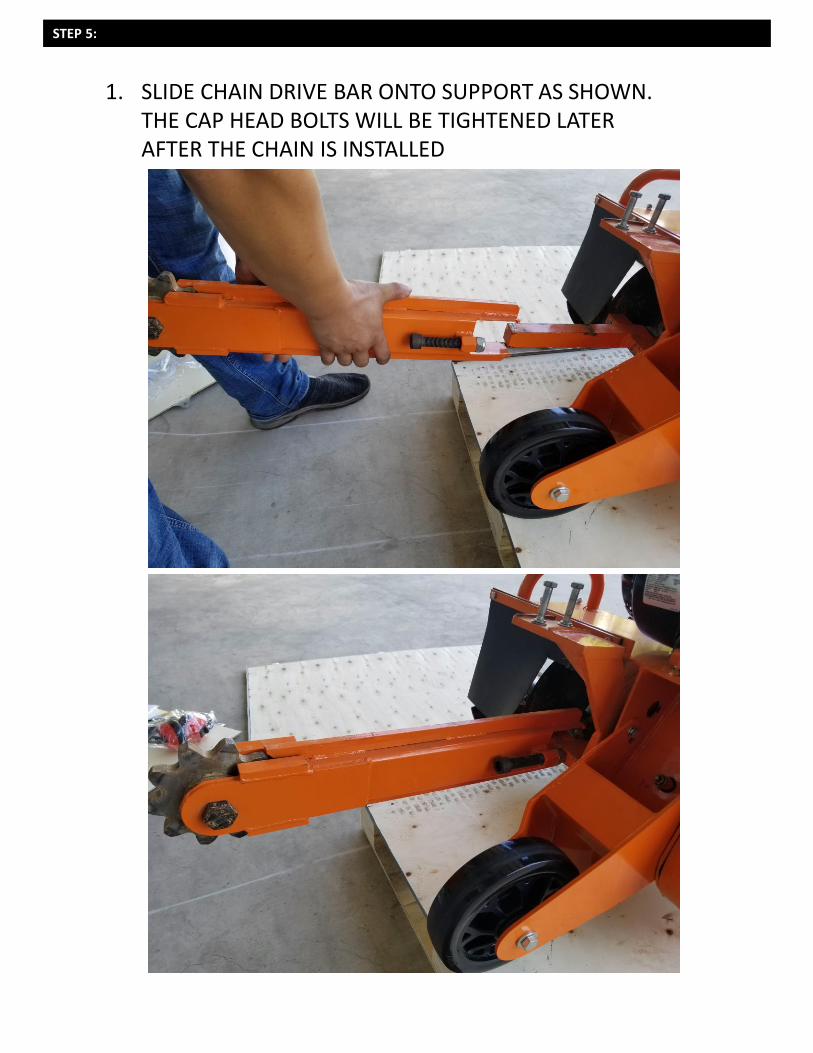
STEP 5:
1. SLIDE CHAIN DRIVE BAR ONTO SUPPORT AS SHOWN. THE CAP HEAD BOLTS WILL BE TIGHTENED LATER AFTER THE CHAIN IS INSTALLED
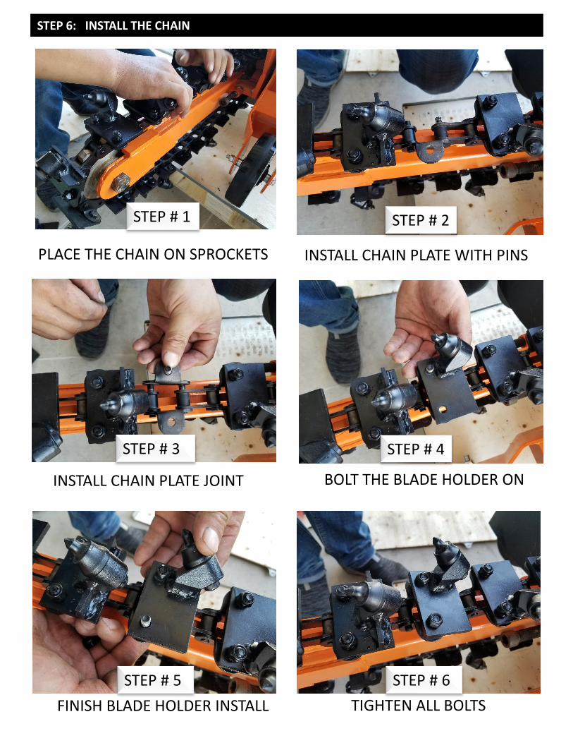
STEP 6: INSTALL THE CHAIN
PLACE THE CHAIN ON SPROCKETS
FINISH BLADE HOLDER INSTALL TIGHTEN ALL BOLTS
BOLT THE BLADE HOLDER ONINSTALL CHAIN PLATE JOINT
INSTALL CHAIN PLATE WITH PINS
STEP # 1
STEP # 6STEP # 5
STEP # 4STEP # 3
STEP # 2
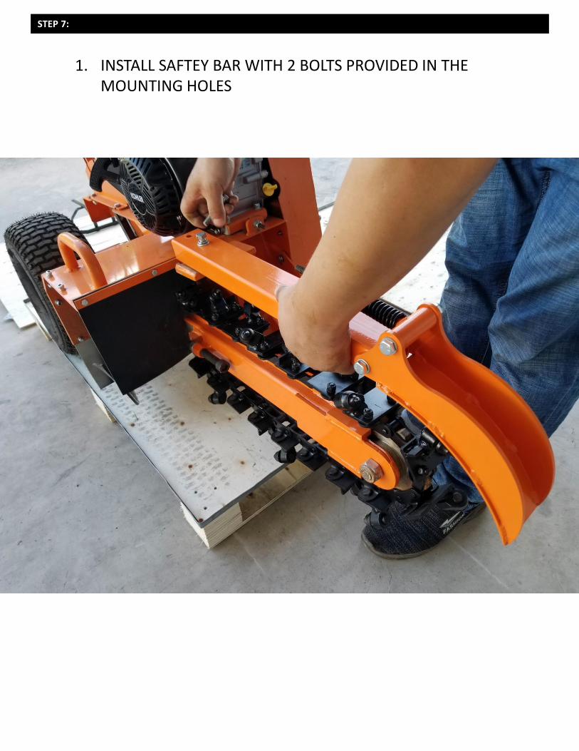
STEP 7:
1. INSTALL SAFTEY BAR WITH 2 BOLTS PROVIDED IN THE MOUNTING HOLES
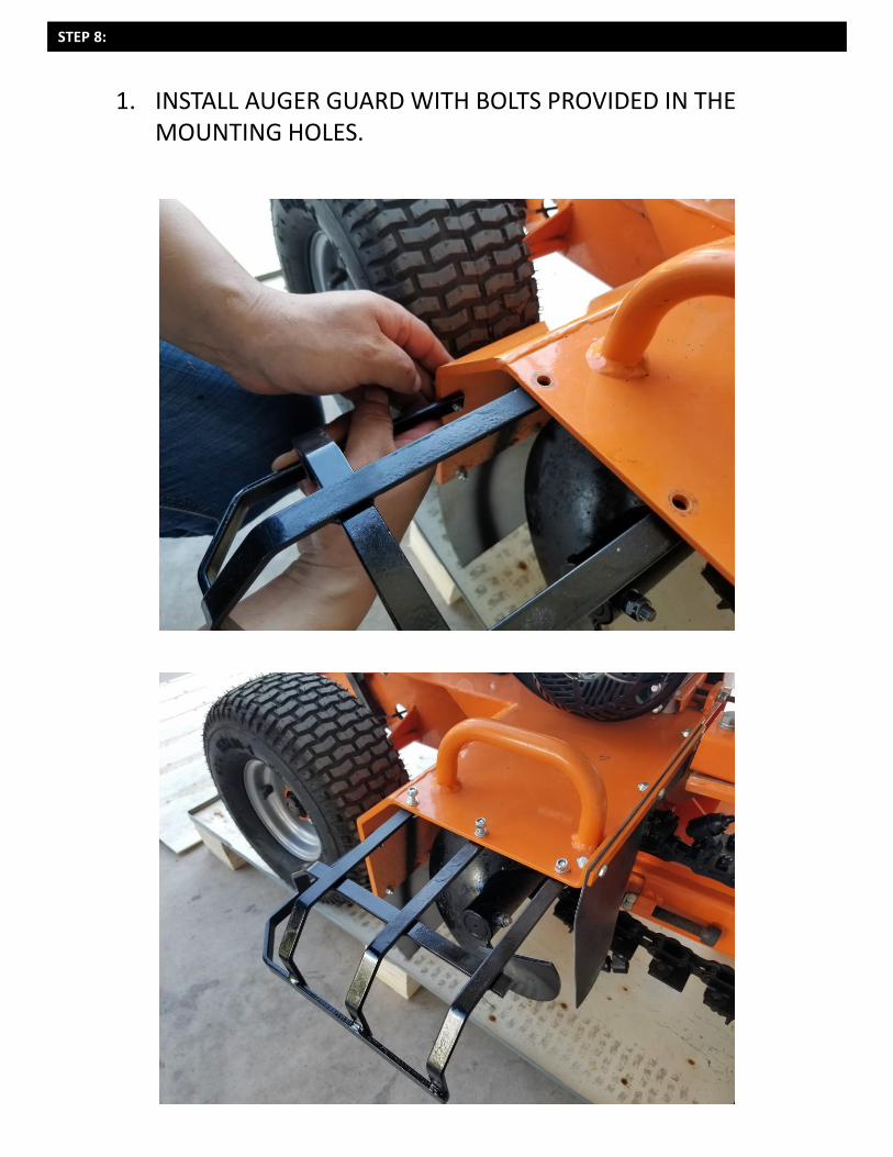
STEP 8:
1. INSTALL AUGER GUARD WITH BOLTS PROVIDED IN THE MOUNTING HOLES.
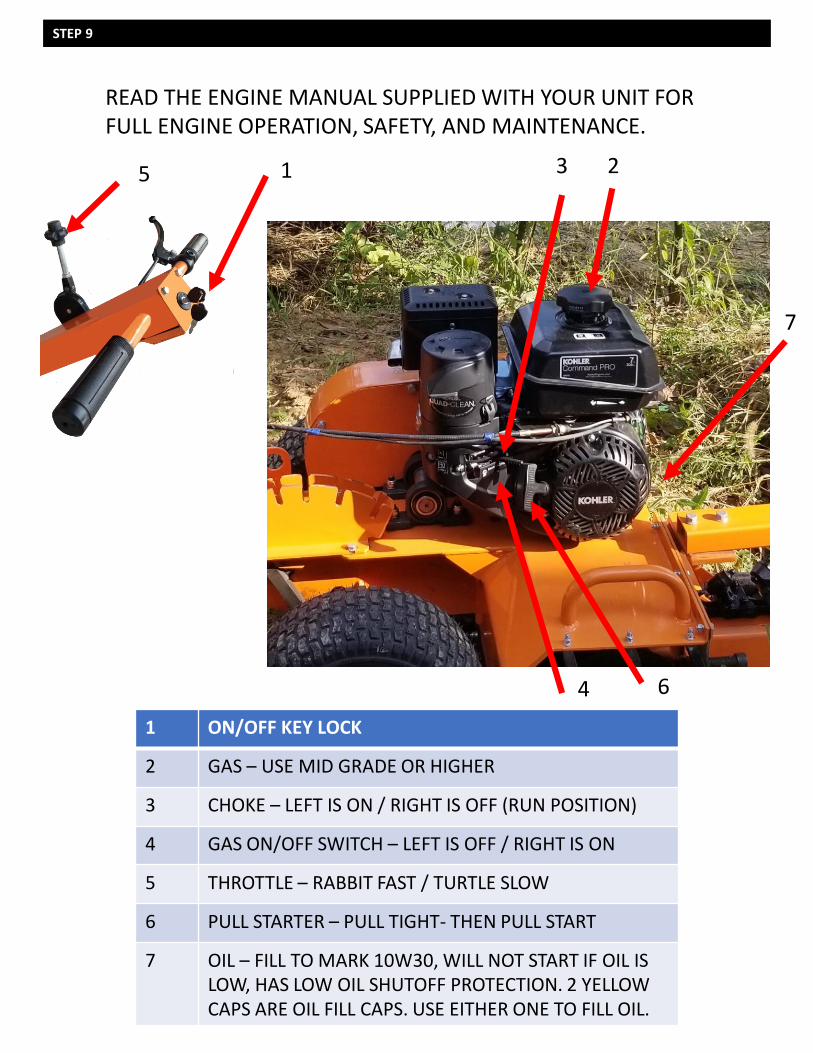
STEP 9
READ THE ENGINE MANUAL SUPPLIED WITH YOUR UNIT FOR FULL ENGINE OPERATION, SAFETY, AND MAINTENANCE.
1 ON/OFF KEY LOCK
2 GAS – USE MID GRADE OR HIGHER
3 CHOKE – LEFT IS ON / RIGHT IS OFF (RUN POSITION)
4 GAS ON/OFF SWITCH – LEFT IS OFF / RIGHT IS ON
5 THROTTLE – RABBIT FAST / TURTLE SLOW
6 PULL STARTER – PULL TIGHT- THEN PULL START
7 OIL – FILL TO MARK 10W30, WILL NOT START IF OIL IS LOW, HAS LOW OIL SHUTOFF PROTECTION. 2 YELLOW CAPS ARE OIL FILL CAPS. USE EITHER ONE TO FILL OIL.
3 2
64
7
5 1
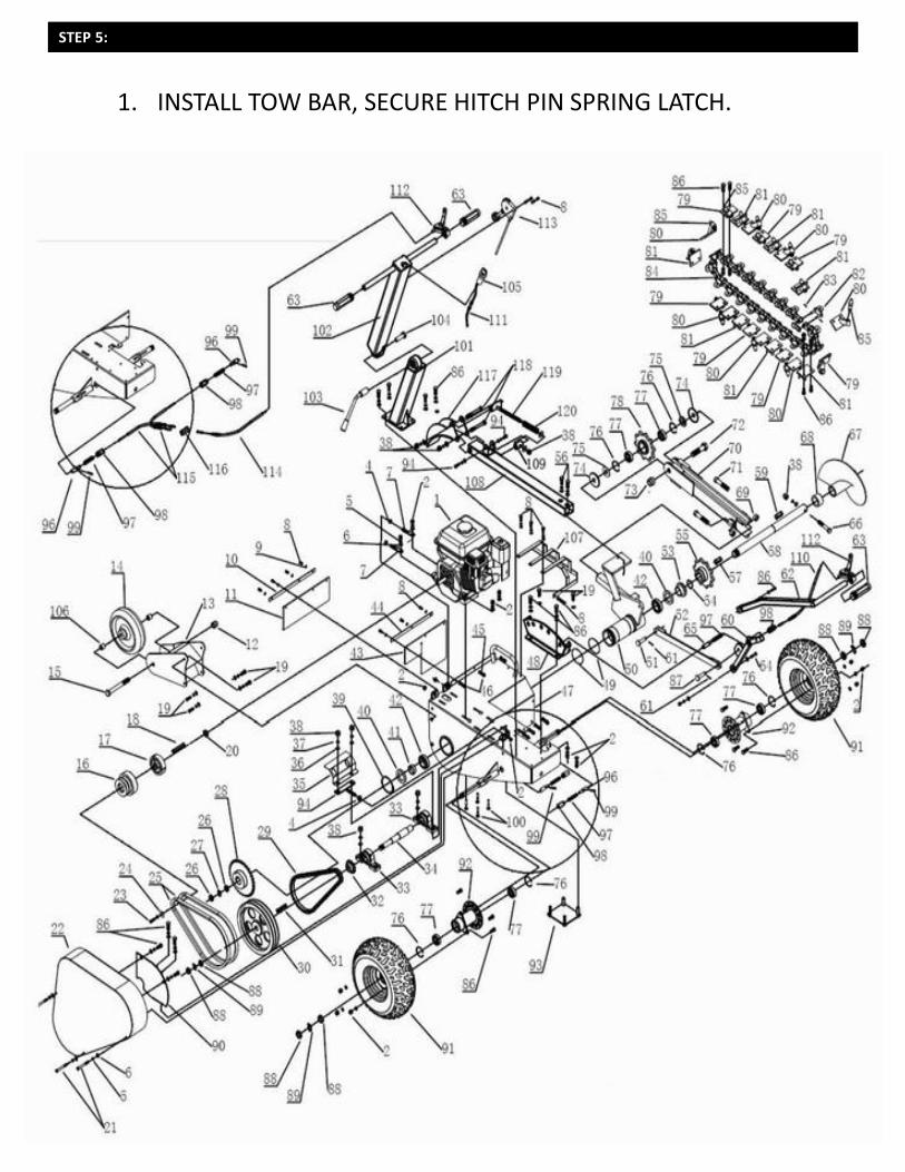
STEP 5:
1. INSTALL TOW BAR, SECURE HITCH PIN SPRING LATCH.
STEP 5:
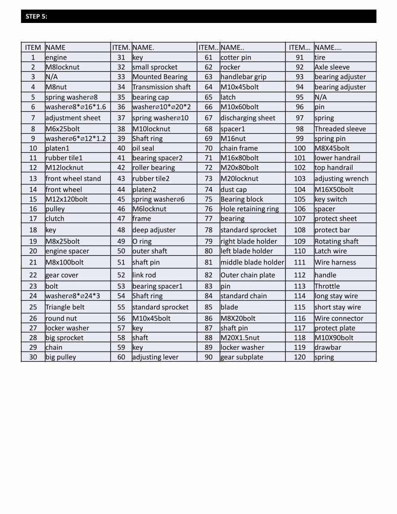
ITEM NAME ITEM. NAME. ITEM.. NAME.. ITEM… NAME….
1 engine 31 key 61 cotter pin 91 tire2 M8locknut 32 small sprocket 62 rocker 92 Axle sleeve3 N/A 33 Mounted Bearing 63 handlebar grip 93 bearing adjuster
4 M8nut 34 Transmission shaft 64 M10x45bolt 94 bearing adjuster
5 spring washer⌀8 35 bearing cap 65 latch 95 N/A6 washer⌀8*⌀16*1.6 36 washer⌀10*⌀20*2 66 M10x60bolt 96 pin
7 adjustment sheet 37 spring washer⌀10 67 discharging sheet 97 spring
8 M6x25bolt 38 M10locknut 68 spacer1 98 Threaded sleeve9 washer⌀6*⌀12*1.2 39 Shaft ring 69 M16nut 99 spring pin
10 platen1 40 oil seal 70 chain frame 100 M8X45bolt11 rubber tile1 41 bearing spacer2 71 M16x80bolt 101 lower handrail12 M12locknut 42 roller bearing 72 M20x80bolt 102 top handrail
13 front wheel stand 43 rubber tile2 73 M20locknut 103 adjusting wrench
14 front wheel 44 platen2 74 dust cap 104 M16X50bolt15 M12x120bolt 45 spring washer⌀6 75 Bearing block 105 key switch16 pulley 46 M6locknut 76 Hole retaining ring 106 spacer17 clutch 47 frame 77 bearing 107 protect sheet
18 key 48 deep adjuster 78 standard sprocket 108 protect bar
19 M8x25bolt 49 O ring 79 right blade holder 109 Rotating shaft20 engine spacer 50 outer shaft 80 left blade holder 110 Latch wire
21 M8x100bolt 51 shaft pin 81 middle blade holder 111 Wire harness
22 gear cover 52 link rod 82 Outer chain plate 112 handle
23 bolt 53 bearing spacer1 83 pin 113 Throttle24 washer⌀8*⌀24*3 54 Shaft ring 84 standard chain 114 long stay wire
25 Triangle belt 55 standard sprocket 85 blade 115 short stay wire
26 round nut 56 M10x45bolt 86 M8X20bolt 116 Wire connector27 locker washer 57 key 87 shaft pin 117 protect plate28 big sprocket 58 shaft 88 M20X1.5nut 118 M10X90bolt29 chain 59 key 89 locker washer 119 drawbar30 big pulley 60 adjusting lever 90 gear subplate 120 spring
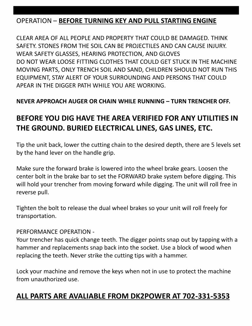
OPERATION – BEFORE TURNING KEY AND PULL STARTING ENGINE
CLEAR AREA OF ALL PEOPLE AND PROPERTY THAT COULD BE DAMAGED. THINK SAFETY. STONES FROM THE SOIL CAN BE PROJECTILES AND CAN CAUSE INJURY.WEAR SAFETY GLASSES, HEARING PROTECTION, AND GLOVESDO NOT WEAR LOOSE FITTING CLOTHES THAT COULD GET STUCK IN THE MACHINE MOVING PARTS, ONLY TRENCH SOIL AND SAND, CHILDREN SHOULD NOT RUN THIS EQUIPMENT, STAY ALERT OF YOUR SURROUNDING AND PERSONS THAT COULD APEAR IN THE DIGGER PATH WHILE YOU ARE WORKING.
NEVER APPROACH AUGER OR CHAIN WHILE RUNNING – TURN TRENCHER OFF.
BEFORE YOU DIG HAVE THE AREA VERIFIED FOR ANY UTILITIES IN THE GROUND. BURIED ELECTRICAL LINES, GAS LINES, ETC.
Tip the unit back, lower the cutting chain to the desired depth, there are 5 levels set by the hand lever on the handle grip.
Make sure the forward brake is lowered into the wheel brake gears. Loosen the center bolt in the brake bar to set the FORWARD brake system before digging. This will hold your trencher from moving forward while digging. The unit will roll free in reverse pull.
Tighten the bolt to release the dual wheel brakes so your unit will roll freely for transportation.
PERFORMANCE OPERATION -Your trencher has quick change teeth. The digger points snap out by tapping with a hammer and replacements snap back into the socket. Use a block of wood when replacing the teeth. Never strike the cutting tips with a hammer.
Lock your machine and remove the keys when not in use to protect the machine from unauthorized use.
ALL PARTS ARE AVALIABLE FROM DK2POWER AT 702-331-5353
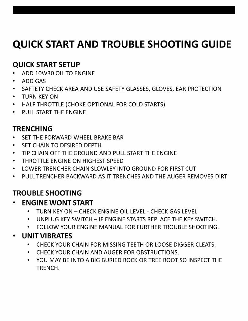
QUICK START AND TROUBLE SHOOTING GUIDE
QUICK START SETUP• ADD 10W30 OIL TO ENGINE• ADD GAS• SAFTETY CHECK AREA AND USE SAFETY GLASSES, GLOVES, EAR PROTECTION• TURN KEY ON• HALF THROTTLE (CHOKE OPTIONAL FOR COLD STARTS)• PULL START THE ENGINE
TRENCHING• SET THE FORWARD WHEEL BRAKE BAR• SET CHAIN TO DESIRED DEPTH• TIP CHAIN OFF THE GROUND AND PULL START THE ENGINE• THROTTLE ENGINE ON HIGHEST SPEED• LOWER TRENCHER CHAIN SLOWLEY INTO GROUND FOR FIRST CUT• PULL TRENCHER BACKWARD AS IT TRENCHES AND THE AUGER REMOVES DIRT
TROUBLE SHOOTING• ENGINE WONT START
• TURN KEY ON – CHECK ENGINE OIL LEVEL - CHECK GAS LEVEL• UNPLUG KEY SWITCH – IF ENGINE STARTS REPLACE THE KEY SWITCH.• FOLLOW YOUR ENGINE MANUAL FOR FURTHER TROUBLE SHOOTING.
• UNIT VIBRATES• CHECK YOUR CHAIN FOR MISSING TEETH OR LOOSE DIGGER CLEATS.• CHECK YOUR CHAIN AND AUGER FOR OBSTRUCTIONS.• YOU MAY BE INTO A BIG BURIED ROCK OR TREE ROOT SO INSPECT THE
TRENCH.
WHAT IS COVEREDDK2 Inc. warrants to the original purchaser of any DK2 product that it will be free and clear of manufacturing defects in workmanship and materials under normal use and service for a period of one (1) year from the date of the original purchase.If within one (1) year from the original date of purchase this product fails due to defect in material or workmanship, Detail K2 will repair, replace, or supply any defective part at our option for DK2 trailer products. DK2 POWER outdoor power equipment is 1-year parts only warranty no labor.Upon expiry of one (1) year, Detail K2 will have no further liability related to the product. Detail K2 does not authorize any party, including its authorized distributors or dealers, to offer any other warranty on behalf of Detail K2 Inc.
KOHLER ENGINES – KOHLER CH SERIES ENGINES COMMERCIAL 3 YR PARTS AND LABOR WARRANTYKOHLER ENGINES – KOHLER SH SERIES ENGINES RESIDENTIAL 2 YR PARTS AND LABOR WARRANTYsee your Kohler manual for specific warranty.DIESEL TRACTORS – Chassis component parts only, no labor, ENGINES – 1 YR KOHLER WARRANTY3PT EQUIPMENT – 1-YEAR parts only, Gearbox drive unit 3-year warranty parts only.DK2 POWER OUTDOOR EQUIPMENT – 1-Year parts only, no labor. 3-year commercial Kohler warranty.
THIS WARRANTY DOES NOT COVER OR APPLY TO:Damage to the product due to misuse, mishandling and abuse(b) Improper installation, maintenance and storage(c) Expendable parts such as nuts and bolts, pins and springs, wiring and switch components, hydraulic hoses and fittings, cutting teeth, cutting chains, cutting blades, throttles, belts and tires.(d) Normal wear and tear(e) Consequential damage & incidental damages such as damage to persons or property
PROCEDURE FOR OBTAINING AN RETURN AUTHORIZATIONWithin the one (1) year warranty period, the purchaser of the product must notify DK2 of the claimed defect and provide proof of original purchase. At this time the validity of the claim will be determined, and if approved replacement parts will be issued. A Return Goods Authorization Number (RGA) will be issued if approved for DK2 Automotive products. No returned product will be accepted under warranty unless accompanied by an RGA# issued by Detail K2 Inc.
RESOLUTION FOR A DEFECTIVE PRODUCTDK2 POWER – Tractors, Chippers, Stump Grinders, Log Splitters, 3pt, and Outdoor Power Equipment.Call DK2 at 702-331-5353 in Las Vegas between 8am-4pm M-F Pacific Time.
DK2 Snow, Trailer, Rack and Winch Products.Call DK2 at 888-277-6960 in Burlington Canada between 8am-4pm M-F Eastern Time.
PLEASE DO NOT RETURN TO THE STOREYOU HAVE A 1 YEAR WARRANTY AND DK2 WILL REPLACE A DEFECTIVE PART FOR FREE
CALL US AT 702-331-5353 FOR FAST WARRANTY PARTS AND QUESTIONS