Embed Size (px)
Citation preview

I 7
I If the specific energy is a minimum dH,/dy = O , we may write
( 1 -29)
Equation 1-29 is valid only for steady flow with parallel streamlines in a channel of small slope. If the velocity distribution coefficient, U, is assumed to be unity, the crite- rion for critical flow becomes
Vc-- - or V = i, = (g A,/B,)O.SO (1 -30) AC 2g 2Bc
- 2
Provided that the tailwater level of the measuring structure is low enough to enable the depth of flow at the channel contraction to reach critical depth, Equations 1-2, 1-23, and 1-30 allow the development of a discharge equation for each measuring device, in which the upstream total energy head (HI) is the only independent variable.
Equation 1-30 states that a t critical flow the average flow velocity V, = (g A,/B,)n.5n It can be proved that this flow velocity equals the velocity with which the smallest disturbance moves in an open channel, as measured relative to the flow. Because of this feature, a disturbance or change in a downstream level cannot influence an up- stream water level if critical flow occurs in between the two cross-sections considered. The 'control section' of a measuring structure is located where critical flow occurs and subcritical, tranquil, or streaming flow passes into supercritical, rapid, or shooting flow.
Thus, if critical flow occurs at the control section of a measuring structure, the upstream water level is independent of the tailwater level; the flow over the structure is then called 'modular'.
1.9 The broad-crested weir
A broad-crested weir is an overflow structure with a horizontal crest above which the deviation from a hydrostatic pressure distribution because of centripetal acce- leration may be neglected. In other words, the streamlines are practically straight and parallel. To obtain this situation the length of the weir crest in the direction of flow (L) should be related to the total energy head over the weir crest as u 7 < H,/L < 0.50. H,/L I 0.07 because otherwise the energy losses above the weir crest c a p b e m a y occur on the-creqt; iI,/L_> 0.50, so tha; onlyl ight curvature-lGs occurTabove the crest and a hydrostatic pressure distribution may be assumed.
If the measuring structure is so designed that there are no significant energy losses in the zone of acceleration upstream of the control section, according to Bernoulli's equation (1-23):
- = c
~
H , = h, + ~V,' /2g = H = y + aV2/2g
(1-31)
where H, equals the total upstream energy head over the weir crest as shown in Figure
28

c c
- - o ‘s, z s ._ O 5k c
Figure 1.10 IhStrdtiOn of terminology
1.10. Substituting Q = VA and putting c1 = 1 .O gives
Q = A (2g(Hl -Y)}~.’~ (1-32)
Provided that critical flow occurs at the control section (y = y,), a head-discharge equation for various throat geometries can now be derived from
Q = Ac {2idHi -YJ)~.’~ ( 1 -33)
1.9.1
For a rectangular control section in which the flow is critical, we may write A, = b,y, and A,/B, = y, so that Equation 1-30 may be written as Y2/2g = ‘I2 y,. Hence:
Broad-crested weir with rectangular control section I (1 -34)
Substitution of this relation and A, = b, into Equation 1-33 gives, after simplification
(1-35)
This formula is based on idealized assumptions such as: absence of centripetal forces
+ bC
Figure I. I 1 Dimensions of a rectangular control section
29

in the upstream and downstream cross-sections bounding the considered zone of acce- leration, absence of viscous effects and increased turbulence, and finally a uniform velocity distribution so that also the velocity distribution coefficient can be omitted. In reality these effects do occur and they must therefore be accounted for by the intro- duction of a discharge coefficient C,. The C,-value depends on the shape and type of the measuring structure.
Q = C 2 2 (-g>o” b, d 3 3 (1 -36)
Naturally in a field installation it is not possible to measure the energy head H I directly and it is therefore common practice to relate the discharge to the upstream water level over the crest in the following way
Q = C C - >,, b, h,1.50 - g ’3 3 (1-37)
’ w h e r e x s a correction coefficient for neglecting the velocity head in the approach channel, c1,v,~/2g. Generally, the approach velocity coefficient
c, = [?T (1 -38)
where u equals the power of h, in the head-discharge equation, being u 1.50 for cc__ a rectangulauontro1,sec~oLT-
Thus C, is greater than unity and is .related to the shape of the .ap.pr.oach channel sectionä6?6o the pow& of’h, in the head-discharge equation.
Values of C, a s o n of the area r&o CdA*/AI are shown in Figure 1.12 for
__I_
coefficient of approach velocity C, 1.20. I I I
- - - - - - - - - triangular control u=2.5 _ -_ parabolic control u=2.0 ~ rectangular control u=l.5
1.15 - control section
1.10 -
1.05
0.5 0.6 O .7 0.8 area rat ioväj c d A*/A,
1.00 - O o .1 0.2 0.3 0.L
A* = wetted area at control sectlon if waterdepth equals y = hl Al = wetted are at head measurement station
Figure 1.12 C, values as a function of the area ratio &CdA*/A~ (from Bos 1977)
30


Figure 1.13 Dimensions of a parabolic control section
As explained in Section 1.9.1, correction coefficients have to be introduced to obtain a practical head-discharge equation. Thus
3 Q = Cd C V J T fg hI2.O (1 -43)
1.9.3 Broad-crested weir with triangular control section
0 0 2 2 For a triangular control section with A, = y: tan- and B, = 2yc tan- (see Figure
1.14), we may write Equation 1-30 as:
Hence
0 2 Substituting those relations and A, = y: tan- into Equation 1-33 gives
I
Figure 1.14 Dimensions of a triangular control section
32
( 1-44)
(1 -45)

Q = '6 [? g]uIO tan!? 2 H12.50 25 5
(1 -46)
For similar reasons as explained in Section 1.9.1, a Cd- and C,-coefficient have to be introduced to obtain a practical head-discharge equation. Thus
16 2 0 2 Q = cd C, 25 [5 g] tan- h,*.50 ( 1 -47)
1.9.4. Broad-crested weir with truncated triangular control section
For weirs with a truncated triangular control section, two head-discharge equations have to be ,used: one for the conditions where flow is confined within the triangular section, and the other, at higher stages, where the presence of the vertical side walls has to be taken into account. The first equation is analogous to Equation 1-47, being
(1 -48) Q = c ~ c , ~ [ ~ ~ ] 16 2 tan- 0 h,2.50 2
which is valid if HI < 1.25 Hb.
The second equation will be derived below. For a truncated triangular control section
0 1 2 2 A, = H: tan- + Bc(y,- Hb) = bcy, - - BcHb
According to Equation 1-30 we may write (see Figure
Hence
.IS)
(1 -49)
( 1 -50)
Figure I . 15 Dimension of a truncated triangular control section
33


It also shows that, if both b, and z, are known the ratio y,/Hl is a function of HI . Values of yc/HI as a function of z, and the ratio Hl/bc are shown in Table I . I .
Substitution of A, = bcy, + zcy,2 into Equation 1-33 and introduction of a discharge coefficient gives as a head-discharge equation
Q = G {bCyc + z,Y,~) {%(Hi - YC))O.~O \ ( 1 -55)
Since for each combination of b,, zo and H,/b,, the ratio y,/H, is given in Table 1.1, the discharge Q can be computed because the discharge coefficient has a predictable value. In this way a Q-HI curve can be obtained. If the approach velocity head vI2/2g is negligible, this curve may be used to measure the discharge. If the approach velocity has a significant value, v12/2g should be estimated and h, = H I -v12/2g may be obtained in one or two steps.
In the literature the trapezoïdal control section is sometimes described as the sum of a rectangular and a triangular control section. Hence, along similar lines as will be shown in Section I . 13 for sharp-crested weirs, a head-discharge equation is obtained by superposing the head-discharge equations valid for a rectangular and a triangular control section. For broad-crested weirs, however, this procedure results in a strongly variable C,-value, since for a given H, the critical depth in the two superposed equa- tions equals 2/3H, for a rectangular and 4/5Hc for a triangular control section. This difference of simultaneous y,-values is one of the reasons why superposition of various head-discharge equations is not allowed. A second reason is the significant difference in mean flow velocities through the rectangular and triangular portions of the control section.
\ /
Figure I . 16 Dimensions of a trapezoidal control section
35
Table 1.1 Values of the ratio yc/HI as a function of& and H,/b, for trapezoïdal control sections
Side slopes of channel, ratio of horizontal to vertical (zc: I )
HdbC Vertical 0.25:1 0.5O:l 0.75:l 1 : l 1.5:1 2.1 2.5:l 3.1 4:l
.o0
.o 1
.o2
.O3
.O4
.O5
.O6
.O7
.O8
.O9
. I O
.I2
.I4
.I6
.18
.20
.22
.24
.26
.28
.30
.32
.34
.36
.38
.40
.42
.44
.46
.48
.so
.60
.70
.80
.90 1 .o I .2 I .4 I .6 1.8 2 3 .4 5 I O 03
,667 ,667 ,667 ,667 ,667 ,667 ,667 ,667 ,667 ,667 ,667 ,667 .667 ,667 .667 ,667 .667 ,667 ,667 ,667 ,667 ,667 ,667 ,667 ,667 ,667 ,667 .667 ,667 ,667 ,667 .667 ,667 ,667 ,667 ,667 ,667 ,667 ,667 ,667 .667 ,667 ,667 ,667 ,667
,667 ,667 ,667 ,668 ,668 ,668 ,669 ,669 ,670 .670 ,670 .67 I ,672 ,672 ,673 ,674 ,674 ,675 ,676 ,676 ,677 ,678 ,678 ,679 ,680 .680 ,681 ,681 ,682 ,683 ,683 ,686 .688 ,692 ,694 .697 ,701 .706 ,709 ,713 .7 17 ,730 ,740 ,748 ,768 ,800
,667 ,667 ,668 ,669 ,670 .670 ,671 ,672 ,672 ,673 ,674 ,675 .676 ,678 .679 .680 .68 1 ,683 ,684 ,685 .686 ,687 ,689 ,690 .691 ,692 ,693 .694 ,695 ,696 ,697 ,701 ,706 ,709 ,713 ,717 .723 ,729 ,733 ,737 .740 ,753 ,762 ,768 ,782 ,800
,667 ,668 ,669 ,670 .67 I ,672 .673 ,674 .675 ,676 .677 .679 .68 I ,683 ,684 ,686 ,688 ,689 ,691 ,693 ,694 ,696 ,697 ,699 ,700 ,701 ,703 ,704 .705 .706 ,708 ,713 .7 18 ,723 ,727 .730 ,737 ,742 ,747 .750 ,754 ,766 ,773 ,777 ,788 ,800
.667 ,668 ,670 .67 I ,672 .674 ,675 ,676 ,678 .679 ,680 ,684 ,686 ,687 ,690 ,692 ,694 ,696 ,698 .699 ,701 ,703 .705 ,706 ,708 .709 ,711 ,712 ,714 .7 15
,717 ,723 ,728 ,732 ,737 ,740 .747 ,752 ,756 ,759 ,762 ,773 ,778 .782 ,791 ,800
,667 ,669 ,671 ,673 ,675 ,677 ,679 .68 1 ,683 ,684 ,686 .690 .693 ,696 ,698 ,701 ,704 ,706 ,709 .7 I 1 ,713 ,715 ,717 ,719 ,721 ,723 ,725 ,727 ,728 ,729 ,730 ,737 .742 ,746 ,750 .754 ,759 ,764 ,767 ,770 ,773 .78 1 ,785 ,788 ,794 ,800
,667 ,670 ,672 ,675 ,677 ,680 ,683 ,685 ,687 ,690 ,692 ,696 ,699 ,703 ,706 ,709 ,712 ,715 ,718 ,720 .723 ,725 ,727 ,729 .73 I .733 ,734 ,736 ,737 ,739 ,740 .741 ,752 ,756 ,759 ,762 .767 .77 I ,774 ,776 ,778 ,785 ,788 ,791 .795 300
.667 ,670 .674 ,677 ,680 .683 ,686 ,689 ,692 ,695 ,697 ,701 ,705 ,709 ,713 .717 ,720 ,723 ,725 ,728 ,730 ,733 ,735 ,737 ,738 ,740 ,742 ,744 .745 .747 ,748 ,754 ,758 ,762 ,766 .768 ,772 .776 ,778 .78 I ,782 ,787 ,790 ,792 ,796 ,800
,667 .67 I .675 .679 ,683 ,686 ,690 ,693 .696 ,698 .701 .706 .711 ,715 ,719 ,723 .726 ,729 ,732 ,734 ,737 ,739’ ,741 ,743 .745 .747 ,748 ,750 ,751 ,752 ,754 ,759 .764 ,767 .770 ,773 .776 ,779 ,781 ,783 .785 ,790 ,792 .794 .797 ,800
,667 .672 ,678 ,683 ,687 ,692 ,696 ,699 ,703 .706 ,709 ,715 ,720 ,725 .729 ,733 ,736 .739 ,742 ,744 .747 ,749 .75 1 ,752 ,754 ,756 .757 .759 ,760 .761 ,762 .161 .77 1 .774 ,776 .778 ,782 ,784 ,786 ,787 ,788 ,792 ,794 ,795 .798 ,800
36

1.9.6 Broad-crested weir with circular control section
For a broad-crested weir with a circular control section we may write (see Figure 1.17) . .
( 1 -56) 1 A, = -d,Z(O-sin€)) 8 B, = d,sin l/,O and ( 1 -57)
d 2 y, = (1 -cos ' / , O ) = d, sin2 1/40
Substitution of values for A, and B, into Equation 1-30 gives
vc A, d, O-sin8 2g 2B, 16 sin ' / ,O -- -
(1 -58)
(1-59)
and because H = H , = y, + v,2/2g we may write the total energy head over the weir crest as
(1 -60)
For each value of yJd, = sin2 1/40 a matching value of the ratios A,/d,Z and HJd, can now be calculated with the above equations. These values, and the additional values on the dimensionless ratios v,2/2gdC and yJH, are presented in Table 1.2.
For a circular control section we may use the general head-discharge relation 'given earlier (Equation 1-33)
Q = C d Ac (2gWi - YJ}' 50 (1-61)
where the discharge coefficient Cd has been introduced for similar reasons to those explained in Section 1.9.1. The latter equation may also be written in terms of dimen- sionless ratios as
Figure 1.17 Dimensions of a circular control section
, 37
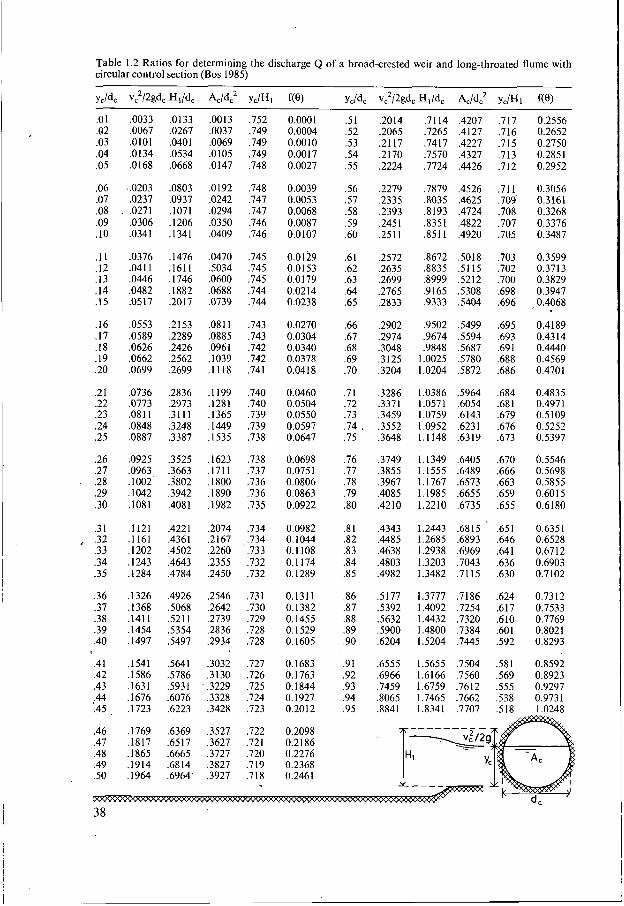
Table 1.2 Ratios for determining the discharge Q of a broad-crested weir and long-throated flume with circular control section (Bos 1985)
Y J ~ , v,2/2gdc ~ , / d , A& y c m 1 fw yc/dC v2/2& HiPC Acid: yc/Hi f(e) .O1 ,0033 ,0133 .O01 3 ,752 0.0001 .5 I .20 14 .7 I 14 ,4207 .7 I7 0.2556 .O2 ,0067 ,0267 ,0037 ,749 0.0004 .52 ,2065 .7265 ,4127 ,716 0.2652 .O3 .O101 ,0401 ,0069 ,749 0.0010 .53 .2 1 17 ,741 7 ,4227 ,715 0.2750 .O4 .O1 34 ,0534 ,0105 ,749 0.001 7 .54 .2 I70 ,7570 ,4327 .7 13 0.2851 .O5 ,0168 ,0668 ,0147 ,748 0.0027 .55 ,2224 ,7724 ,4426 ,712 0.2952
.O6 ..O203 .O803 ,0192 ,748 0.0039 .56 ,2279 .7879 ,4526 ,711 0.3056
.O7 ,0237 ,0937 ,0242 ,747 0.0053 .57 .2335 ,8035 ,4625 ,709 0.3161
.O8 . ,0271 ,1071 ,0294 ,747 0.0068 .58 ,2393 ,8193 ,4724 ,708 0.3268
.O9 ,0306 ,1206 .O350 ,746 0.0087 .59 ,2451 ,8351 ,4822 ,707 0.3376
. I O ,0341 ,1341 ,0409 ,746 0.0107 .60 ,2511 ,8511 ,4920 .705 0.3487
. I 1 ,0376 ,1476 .O470 ,745 0.0129 .61 ,2572 3672 ,5018 .703 0.3599
.I2 ,0411 ,1611 SO34 ,745 0.0153 .62 ,2635 ,8835 ,5115 ,702 0.3713
.I3 ,0446 ,1746 ,0600 ,745 0.0179 .63 ,2699 . ,8999 ,5212 .700 0.3829
.I4 ,0482 ,1882 ,0688 ,744 0.0214 .64 ,2765 .9 165 ,5308 ,698 0.3947
.15 ,0517 ,2017 .O739 ,744 0.0238 .65 ,2833 .9333 ,5404 ,696 ,0.4068
.16 ,0553 ,2153 ,0811 .743 0.0270 .66 ,2902 ,9502 .5499 ,695 0.4189
.I7 ,0589 ,2289 ,0885 ,743 0.0304 .67 ,2974 ,9674 ,5594 ,693 0.4314
. I8 ,0626 ,2426 .O96 1 ,742 0.0340 .68 .3048 ,9848 S687 .69 1 0.4440
.I9 ,0662 ,2562 ,1039 ,742 0.0378 .69 .3125 1.0025 S780 ,688 0.4569
.20 ,0699 ,2699 . I I I8 ,741 0.0418 .70 ,3204 1.0204 ,5872 ,686 0.4701
.21 .O736 ,2836 . I I99 ,740 0.0460 .71 .3286 1.0386 S964 ,684 0.4835
.22 ,0773 .2973 .I281 ,740 0.0504 .72 ,3371 1 .O571 ,6054 .681 0.497 1
.23 .O8 1 I .3 1 1 1 . I365 ,739 0.0550 .73 ,3459 1.0759 ,6143 ,679 0.5109
.24 ,0848 ,3248 .I449 ,739 0.0597 .74 . ,3552 1.0952 ,6231 .676 0.5252
.25 .O887 ,3387 .I535 ,738 0.0647 .75 .3648 1.1148 .6319 ,673 0.5397
.26 ,0925 ,3525 ,1623 ,738 0.0698 .76 ,3749 1.1349 ,6405 ,670 0.5546
.27 ,0963, ,3663 ,1711 ,737 0.0751 .77 ,3855 1.1555 ,6489 ,666 0.5698
.28 ,1002 ,3802 ,1800 ,736 0.0806 .78 .3967 1.1767 ,6573 ,663 0.5855
.29 .IO42 ,3942 ,1890 ,736 0.0863 .79 ,4085 1.1985 ,6655 ,659 0.6015
.30 ,1081 ,4081 ,1982 ,735 0.0922 3 0 .4210 1.2210 ,6735 ,655 0.6180
.3 1 . I 12 I ,4221 .2074 .734 0.0982 .8 I ,4343 1.2443 .68 I5 ,651 0.635 1 , .32 . I 161 ,4361 ,2167 ,.734 0.1044 3 2 ,4485 1.2685 .6893 ,646 0.6528
.33 ,1202 ,4502 ,2260 ,733 0.1 108 .83 ,4638 1.2938 ,6969 ,641 0.6712
.34 ,1243 ,4643 ,2355 ,732 0.1 I74 .84 ,4803 1.3203 ,7043 ,636 0.6903
.35 .1284 ,4784 ,2450 ,732 0.1289 .85 ,4982 1.3482 ,7115 ,630 0.7102
.36 ,1326 ,4926 ,2546 ,731 0.1311 3 6 ,5177 1.3777 ,7186 ,624 0.7312
.37 ,1368 ,5068 ,2642 ,730 O. 1382 .87 ,5392 1.4092 ,7254 ,617 0.7533
.38 .1411 ,5211 ,2739 ,729 0.1455 3 8 ,5632 1.4432 ,7320 ,610 0.7769
.39 ,1454 ,5354 .2836 ,728 0.1529 .89 S900 1.4800 .7384 ,601 0.8021
.40 ,1497 ,5497 .2934 ,728 0.1605 .90 ,6204 1.5204 .7445 ,592 0.8293
.41 .I541 ,5641 ,3032 ,727 0.1683 .91 .6555 1.5655 .7504 ,581 0.8592
.42 ,1586 .5786 ,3130 ,726 0.1763 .92 .6966 1.6166 ,7560 ,569 0.8923
.43 ,1631 ,5931 ' ,3229 ,725 0.1844 .93 ,7459 1.6759 ,7612 ,555 0.9297 ,44 ,1676 ,6076 .3328 ,724 0.1927 .94 .8065 1.7465 .7662 ,538 0.9731 .45 ,1723 ,6223 .3428 ,723 0.201 2 .95 ,8841 1.8341 ,7707 .5 18 I .O248
38

Substitution of Equations 1-56, 1-58, and 1-60 into Equation 1-62 yields
(1 -63)
(0 - sin
8(8 sin where f(e) = is a shape factor for the control section. e
2
If d, is known and HI is set to a given value, the related value of f(0) can be read from Table 1.2. Substitution of this value and the Cd value to Equation 1.62 yields the discharge Q. The iterative procedure of Section 1.9.5 should be used to transform this Hl-Q relationship int? an h,-Q relationship.
Table 1.2 also contains columns presenting dimensionless values for the velocity head, water depth, and related area of flow.
1.10 ' Short-crested weir
The basic difference between a broad-crested weir and a short-crested weir is that CL- n o < h m T 6 ? 3 h e o r t crest can the curvatureTf the s t E l i G g e neglected; there is thG no h y d r o s t a f i m distribution. The two-dimensional flow pattern over a short-crested weir can be described by the equations of motion in the s- and n-direc- tions whereby the problem of determining the local values of v and r is introduced.
m, like those involved in three-dimensional flow, is not tractable by existing made to hydraulic model tests. theory-and thus recours_e t~be - 7
U.S. Soil Conservation Service Protile Weir
Cylindrical crastad weir
Figure 1.18 Various types of short-crested weirs
39

Thus experimental data are made to fit a head-discharge equation which is structurally similar to that of a broad-crested weir b.utjn_which the dischape coefficient expresses - the influence ,of streamline curvature in addition to these factorssplaine_d in S s
*act, the same measuring structure can act as a broad-crested weir for low heads (H,/L < 0.50), while with an increase of head (H,/L > 0.50) the influence of the streamline curvature becomes significant, and the structure acts as a short-crested weir. For practical purposes, a short-crested weir with rectangular control section has a head-discharge equation similar to Equation 1-37, i.e.
m ____.
Q = C ' C - [' -g ]05°'b, h,l.SO ' 3 3 (1 -64)
The head-discharge equations of short-crested weirs with non-rectangular throats are structurally similar to those presented in Section 1.9. An exception to this rule is pro- vided by those short-crested weirs which have basic characteristics in common with sharp-crested weirs. As an example we mention the WES-spillway which is shaped according to the lower nappe surface of an aerated sharp-crested weir and the triangu- lar profile weir whose control section is situated- above a separation bubble down- stream of a sharp weir crest.
Owing to the-gressure and velocity distributions above the w-as indicated i i F i s r e 1.19, the discharge coefficient (-cd) of a short-crested weir TsAgher than
T h a t of a broad-creste-d-xeir,The rate of departure from the hydrostatic pressure d i s t r bution is defined by the local centripetal acceleration v2/r (see Equation 1-10).
-P-
(1 -65)
Depending on the degree of curvature in the overflowing nappe, an underpressure may develop near the weir crest, while under certain circumstances even vapour pres- sure can be reached (see also Annex 1). If the overfalling nappe is not in contact with the body of the weir, the air pocket beneath the nappe should be aeratedto avoid an underpressure,wJhich increases the streamline curvature a-For mÓre details on this aeration demand the reader is referred to Section 1.14.
I I / I v; 129 I p
q E
Figure 1.19 Velocity and pressure distribution above a short-crested weir
40


![Riverside Topographic Assessment Methodology · The Broad Crested Weir Equation (Ref: Open Channel Hydraulics, Van Te Chow) used is listed below: Flow [m3/s] = 1.55 x breach width](https://img.pdfslide.net/doc/110x75/5f2fdad5770424727d70ba1b/riverside-topographic-assessment-methodology-the-broad-crested-weir-equation-ref.jpg)


![Channel Slope Effect on Energy Dissipation of Flow over Broad Crested … · 2016-12-09 · broad crested weir by[10], where the rapid redistributions of both velocity and pre s-sure](https://img.pdfslide.net/doc/110x75/5e7c6d18a13f4d69360b113a/channel-slope-effect-on-energy-dissipation-of-flow-over-broad-crested-2016-12-09.jpg)