Embed Size (px)
Citation preview

(19) United States (12) Patent Application Publication (10) Pub. No.: US 2017/0211378 A1
DERKACZ. et al.
US 2017021 1378A1
(43) Pub. Date: Jul. 27, 2017
(54)
(71)
(72)
(21)
(22)
(86)
OPTIMIZING DOWNHOLE DATA COMMUNICATION WITHAT BIT SENSORS AND NODES
Applicant: EVOLUTION ENGINEERING INC., Calgary (CA)
Inventors: Patrick R. DERKACZ, Calgary (CA); Aaron William LOGAN, Calgary (CA); Justin C. LOGAN, Calgary (CA); Jili LIU, Calgary (CA); David A. SWITZER, Calgary (CA); Robert HARRIS, Calgary (CA); Barry Daniel BUTERNOWSKY, Calgary (CA): Kurtis WEST, Calgary (CA)
Appl. No.: 15/321,675
PCT Fed: May 8, 2015
PCT No.: PCT/CA2O1S/OSO422
S 371 (c)(1), (2) Date: Dec. 22, 2016
Surface Equipment
Related U.S. Application Data (60) Provisional application No. 62/015,817, filed on Jun.
23, 2014.
Publication Classification
(51) Int. Cl. E2IB 47/12 (2006.01)
(52) U.S. Cl. CPC ............ E2IB 47/122 (2013.01); E2IB 47/04
(2013.01)
(57) ABSTRACT
Data is communicated from sensors at a downhole location near a drill bit to Surface equipment. Communication to the Surface equipment may be direct or may pass through a series of nodes. The nodes in some cases are intelligently reconfigured to achieve desired data rates, achieve power management goals, and/or compensate for failed nodes.
US 2017/0211378 A1 Jul. 27, 2017 Sheet 1 of 8 Patent Application Publication
%ZZZZZZZZZZZZZZZZZZZZZZZZZZZZZZZZZZZZZZZZZZZZZZZZZZZZZZZZZZ2222222222222222222222222D. ZZZZZ F.G. 1

Patent Application Publication Jul. 27, 2017 Sheet 2 of 8 US 2017/021 1378A1
22 CONTROLLER
SENSORS 23
FIG 2

Patent Application Publication Jul. 27, 2017. Sheet 3 of 8 US 2017/021 1378A1
FIG. 3

Patent Application Publication Jul. 27, 2017. Sheet 4 of 8 US 2017/021 1378 A1
Surface Equipment
Surface Equipment
FIG. 4A F.G. 4B

Patent Application Publication Jul. 27, 2017. Sheet 5 of 8 US 2017/021 1378 A1
Surface Equipment
FIG. 4C

Patent Application Publication Jul. 27, 2017 Sheet 6 of 8 US 2017/021 1378A1
Surface Equipment
FG. 4D

Patent Application Publication Jul. 27, 2017 Sheet 7 of 8
TRANSMITTING J L A OV PULSE
US 2017/021 1378A1

Patent Application Publication Jul.27, 2017. Sheet 8 of 8 US 2017/0211378 A1
3OG
1.
3OF
3OD
V
N F.G. 6
US 2017/021 1378 A1
OPTIMIZING DOWNHOLE DATA COMMUNICATION WITHAT BIT SENSORS
AND NODES
TECHNICAL FIELD
0001. This application relates to subsurface drilling, spe cifically, to data communication to and/or from downhole electronic systems. Embodiments are applicable to drilling wells for recovering hydrocarbons.
BACKGROUND
0002 Recovering hydrocarbons from subterranean Zones typically involves drilling wellbores. 0003 Wellbores are made using surface-located drilling equipment which drives a drill string that eventually extends from the Surface equipment to the formation or Subterranean Zone of interest. The drill string can extend thousands of feet or meters below the surface. The terminal end of the drill string includes a drill bit for drilling (or extending) the wellbore. Drilling fluid, usually in the form of a drilling “mud, is typically pumped through the drill string. The drilling fluid cools and lubricates the drill bit and also carries cuttings back to the Surface. Drilling fluid may also be used to help control bottom hole pressure to inhibit hydrocarbon influx from the formation into the wellbore and potential blow out at surface. 0004 Bottom hole assembly (BHA) is the name given to the equipment at the terminal end of a drill string. In addition to a drill bit, a BHA may comprise elements such as: apparatus for steering the direction of the drilling (e.g. a steerable downhole mud motor or rotary steerable system); sensors for measuring properties of the Surrounding geo logical formations (e.g. sensors for use in well logging); sensors for measuring downhole conditions as drilling pro gresses; one or more systems for telemetry of data to the Surface; stabilizers; heavy weight drill collars; pulsers; and the like. The BHA is typically advanced into the wellbore by a string of metallic tubulars (drill pipe). 0005 Modern drilling systems may include any of a wide range of mechanical/electronic systems in the BHA or at other downhole locations. Downhole electronics may pro vide any of a wide range of functions including, without limitation: data acquisition; measuring properties of the Surrounding geological formations (e.g. well logging); mea Suring downhole conditions as drilling progresses; control ling downhole equipment; monitoring status of downhole equipment; directional drilling applications; measuring while drilling (MWD) applications; logging while drilling (LWD) applications; measuring properties of downhole flu ids; and the like. Downhole electronics may comprise one or more systems for telemetry of data to the Surface; collecting data by way of sensors (e.g. sensors for use in well logging) that may include one or more of vibration sensors, magne tometers, inclinometers, accelerometers, nuclear particle detectors, electromagnetic detectors, acoustic detectors, and others; acquiring images; measuring fluid flow; determining directions; emitting signals, particles or fields for detection by other devices; interfacing to other downhole equipment; sampling downhole fluids; etc. 0006 Downhole electronics may communicate a wide range of information to the surface by telemetry. Telemetry information can be invaluable for efficient drilling opera tions. For example, telemetry information may be used by a
Jul. 27, 2017
drill rig crew to make decisions about controlling and steering the drill bit to optimize the drilling speed and trajectory based on numerous factors, including legal bound aries, locations of existing wells, formation properties, hydrocarbon size and location, etc. A crew may make intentional deviations from the planned path as necessary based on information gathered from downhole sensors and transmitted to the surface by telemetry during the drilling process. The ability to obtain and transmit reliable data from downhole locations allows for relatively more economical and more efficient drilling operations.
0007 Data communication to and from downhole sys tems presents significant difficulties. There are several known telemetry techniques. These include transmitting information by generating vibrations in fluid in the bore hole (e.g. acoustic telemetry or mud pulse (MP) telemetry) and transmitting information by way of electromagnetic signals that propagate at least in part through the earth (EM telem etry). Other telemetry techniques use hardwired drill pipe, fibre optic cable, or drill collar acoustic telemetry to carry data to the Surface.
0008 Advantages of EM telemetry, relative to MP telem etry, include generally faster baud rates, increased reliability due to no moving downhole parts, high resistance to lost circulating material (LCM) use, and suitability for air/ underbalanced drilling. An EM System can transmit data without a continuous fluid column; hence it is useful when there is no drilling fluid flowing. This is advantageous when a drill crew is adding a new section of drill pipe as the EM signal can transmit information (e.g. directional informa tion) while the drill crew is adding the new pipe. Disadvan tages of EM telemetry include lower depth capability, incompatibility with some formations (for example, high salt formations and formations of high resistivity contrast), and some market resistance due to acceptance of older established methods. Also, as the EM transmission is strongly attenuated over long distances through the earth formations, it requires a relatively large amount of power so that the signals are detected at surface. The electrical power available to generate EM signals may be provided by batteries or another power source that has limited capacity. 0009. A typical arrangement for electromagnetic telem etry uses parts of the drill String as an antenna. The drill string may be divided into two conductive sections by including an insulating joint or connector (a 'gap Sub”) in the drill String. The gap Sub is typically placed at the top of a bottom hole assembly such that metallic drill pipe in the drill string above the BHA serves as one antenna element and metallic sections in the BHA serve as another antenna element. Electromagnetic telemetry signals can then be transmitted by applying electrical signals between the two antenna elements. The signals typically comprise very low frequency AC signals applied in a manner that codes infor mation for transmission to the Surface. (Higher frequency signals attenuate faster than low frequency signals.) The electromagnetic signals may be detected at the Surface, for example by measuring electrical potential differences between the drill string or a metal casing that extends into the ground and one or more ground rods. 0010. There remains a need for systems for effectively communicating data to and from downhole electronic sys temS.

US 2017/021 1378 A1
SUMMARY
0011. The invention has a number of aspects. Some aspects provide methods of transmitting data along a drill string. Other aspects provide systems, kits and apparatuses for transmitting data along a drill string. Other aspects provide a method for data telemetry from a downhole location 0012. One aspect of the invention provides a method for transmitting data along a drill string comprising transmitting a first signal from a first node based on a first transmission setting while the first node is located at a first depth, measuring an aspect of the first signal at a second node, determining a second transmission setting based on the measurement of the measured aspect of the first signal, advancing the drill string so that the second node is proxi mate to the first depth and transmitting a second signal at the second transmission setting from the second node while the second node is located proximate to the first depth. 0013. In some embodiments, the aspect comprises one or more of signal strength of the first signal at the second node, a harmonic frequency of the first signal and a signal-to-noise ratio of the first signal at the second node. 0014. In some embodiments, the setting comprises one or more of a frequency setting, an amplitude setting and again setting. In some embodiments, gain is increased with depth. 0015. In some embodiments, the method comprises trans mitting signals from the first node at a first frequency and receiving signals at the first node at a second frequency, wherein the first frequency is different from the second frequency. Signals may also be transmitted from the second node at the second frequency and receiving signals at the second node at the first frequency 0016. In some embodiments, the first frequency is filtered out at a receiver of the first node. In other embodiments, a plurality of frequencies are filtered out at the first node, including the first frequency. Filtering may comprise har monic separation. 0017. In some embodiments, signals are transmitted from the first node at a first polarity and signals are transmitted from the second node at a second polarity, the first polarity opposing the second polarity. 0.018. In some embodiments, transmitting a second signal at the second transmission setting comprises decoding and buffering the first signal. In some embodiments, transmitting a second signal at the second transmission setting comprises adding additional data to the first signal. Adding additional data to the first signal may comprise providing a node identifier with the additional data. The node identifier may comprise a time stamp or an incremental count. 0019. In some embodiments, the first node and the sec ond node each comprise an electrically insulating gap and an electromagnetic telemetry transceiver. 0020. In some embodiments, signals are transmitted in a second direction, opposite the first direction in which signals are transmitted using a first and second frequency, using a third and fourth frequency wherein the first, second, third and fourth frequencies are different from one another and the first direction is opposite the second direction. The third and fourth frequencies may be lower than the first and second frequencies. 0021. Another aspect of the invention provides a system for transmitting data along a drill String. The system may comprise a first node operable to transmit signals positioned along the drill string, the first node in communication with
Jul. 27, 2017
one or more sensors, the first node configured to transmit a first signal based on a first transmission setting, a second node operable to transmit signals positioned along the drill string and spaced apart from the first node, the second node in communication with the first node, the second node configured to measure an aspect of a first signal transmitted by the first node while the first node is located at a first depth and a controller configured to determine a second transmis sion setting based on the aspect of the first signal measured by the second node. The second node may be configured to transmit a second signal at the second transmission setting while the second node is located proximate to the second depth. 0022. In some embodiments, the first node is configured to transmit signals at a first frequency and receive signals at a second frequency, wherein the first frequency is different from the second frequency. In some embodiments, the second node is configured to transmit signals at the second frequency and receive signals at the first frequency. The first node may be configured to filter out at least the first frequency at a receiver of the first node and/or the first node may comprise a filter connected to block at least the first frequency from reaching a receiver of the first node. The filter may use harmonic separation. 0023. In some embodiments, the first node is configured to transmit signals at a first polarity and the second node is configured to transmit signals at a second polarity, the first polarity opposing the second polarity. 0024. Another aspect provides a method for data telem etry comprising providing a drill string in a wellbore, the wellbore passing through formations such that a range of electromagnetic telemetry transmissions varies as a function of depth in the wellbore, passing data from a downhole location to the Surface using a plurality of telemetry relay devices between the downhole location and the surface, identifying first and second non-adjacent ones of the telem etry relay devices such that the second one of the telemetry relay devices is within the range for electromagnetic telem etry transmissions corresponding to the location of the first one or the telemetry relay devices and inhibiting operation of one or more of the telemetry relay devices between the first and second ones of the telemetry relay devices. 0025. In some embodiments, the method comprises advancing the drill String until the range of electromagnetic telemetry transmissions corresponding to the location of the first one of the telemetry relay devices is reduced and then activating one or more of the one or more electromagnetic telemetry relay devices between the first and second ones of the electromagnetic telemetry relay devices. 0026. In some embodiments, the method comprises monitoring the range of the electromagnetic telemetry sig nals by transmitting electromagnetic telemetry signals from a transmitter on the drill String and receiving the electro magnetic telemetry signals transmitted by the transmitter at a plurality of the electromagnetic telemetry relay devices. 0027. In some embodiments, the transmitter is a trans mitter of one of the electromagnetic telemetry relay devices. 0028. Another aspect provides a method for data telem etry comprising providing a plurality of telemetry relay devices at locations spaced apart along a drill string, each of the telemetry relay devices comprising an electromagnetic telemetry signal receiver and an electromagnetic telemetry signal transmitter, moving the drill string in a wellbore, identifying a first region of the wellbore in which electro

US 2017/021 1378 A1
magnetic telemetry transmissions are attenuated more strongly and a second region of the wellbore in which electromagnetic telemetry transmissions are attenuated less strongly, passing data up the drill string by sequentially relaying the data by electromagnetic telemetry from one of the relay devices to another and automatically inhibiting operation of some of the telemetry relay devices while those telemetry relay devices are in the second region. 0029. Further aspects of the invention and features of example embodiments are illustrated in the accompanying drawings and/or described in the following description.
BRIEF DESCRIPTION OF THE DRAWINGS
0030 The accompanying drawings illustrate non-limit ing example embodiments of the invention. 0031 FIG. 1 is a schematic view of a drilling operation. 0032 FIG. 2 is a schematic view of a lower end of a drill String. 0033 FIG. 3 is a block diagram of a node for a downhole data network. 0034 FIGS. 4A through 4D are schematic views showing various options for transmitting data to Surface equipment. 0035 FIG. 5 is a schematic view of a drill string section having several EM telemetry nodes. 0036 FIG. 6 is a block diagram showing a plurality of nodes receiving and transmitting data.
DESCRIPTION
0037. Throughout the following description specific details are set forth in order to provide a more thorough understanding to persons skilled in the art. However, well known elements may not have been shown or described in detail to avoid unnecessarily obscuring the disclosure. The following description of examples of the technology is not intended to be exhaustive or to limit the system to the precise forms of any example embodiment. Accordingly, the description and drawings are to be regarded in an illustra tive, rather than a restrictive, sense. 0038 FIG. 1 shows schematically an example drilling operation. A drill rig 10 drives a drill string 12 which includes sections of drill pipe that extend to a drill bit 14. The illustrated drill rig 10 includes a derrick 10A, a rig floor 10B and draw works 10C for supporting the drill string. Drill bit 14 is larger in diameter than the drill string above the drill bit. An annular region 15 Surrounding the drill string is typically filled with drilling fluid. The drilling fluid is pumped through a bore in the drill string to the drill bit and returns to the Surface through annular region 15 carrying cuttings from the drilling operation. As the well is drilled, a casing 16 may be made in the wellbore. Ablow out preventer 17 is supported at a top end of the casing. The drill rig illustrated in FIG. 1 is an example only. The methods and apparatus described herein are not specific to any particular type of drill rig. 0039. One aspect of this invention provides downhole data networks, nodes for downhole data networks, and methods for transmitting data from an electronics system in a wellbore to the surface by way of a number of relay nodes. In some embodiments, nodes of the network have built-in intelligence which controls the nodes to perform one or more of:
0040 0041
managing power consumption; maintaining a desired data rate;
Jul. 27, 2017
0.042 maintaining reliable data transmission. 0043. In some embodiments, the nodes communicate with one another and/or with surface equipment by EM telemetry. The nodes may communicate with one another using frequencies that are high in comparison to the fre quencies normally used for EM telemetry. In some embodi ments, EM signals from the nodes have relatively short ranges (e.g. less than about 1000 feet-approximately 300 m and typically 200 feet-approximately 60 m or less.). Nodes may be spaced apart such that each node can transmit to one or more other nodes. In some embodiments adjacent nodes are 60 to 250 feet (about 20 m to about 80 m) apart. 0044. In other embodiments, the drill string is separated into a plurality of conductive sections that are electrically isolated by one or more electrically insulating gaps, such as is described in International Publication No. WO 2015/ O31973.
0045 Another aspect of the invention provides an EM telemetry system having a transmitter located between a mud motor and a drill bit. This EM telemetry system may be applied to communicate data directly to a Surface-located receiver or to transmit data to the Surface by way of a system comprising one or more data relays. In some embodiments, the range of transmitted EM telemetry signals is optimized by providing a relatively large gap for the EM telemetry transmitter. These aspects may be used individually and may also be combined.
0046. One advantage of using EM telemetry to transmit data from a location below a mud motor to a location above the mud motor is that EM telemetry signals are not affected significantly by the higher rotation speed of the parts of the drill string below the mud motor. 0047. In some embodiments, the power of the EM telem etry transmitter located below the mud motor is relatively low. For example, the transmission power may be two watts or less. Such low power transmission may be sufficient to transmit an EM telemetry signal to a receiver located nearby, for example, a receiver located in the BHA above the mud motor. The receiver may be associated with a battery or other power source which permits higher power telemetry trans missions either all the way to the surface or to another receiver in a node farther up the drill string. 0048. In some embodiments, an EM telemetry transmitter has two or more operating nodes. One node may use low-frequency (e.g. <20 HZ) higher-power signals to trans mit over a long range. Another node may use higher fre quencies and optionally lower power to transmit data over a shorter range. 0049 FIG. 2 shows schematically the lower end of a drill string 12. FIG. 2 shows a mud motor 18 connected to drive a drill bit 19. An electrically insulating gap 20 is provided in the drill string between the mud motor 18 and the drill bit 19. Gap 20 may, for example, be provided in a sub which is coupled to the mud motor at one end and to the drill bit at another end. In an alternative embodiment, gap 20 is inte grated with mud motor 18. In another alternative embodi ment, gap 20 is integrated with drill bit 19. 0050. An EM telemetry transmitter indicated schemati cally by 21 is connected across gap 20. EM telemetry transmitter 21 is configured to apply a potential difference across gap 20. By altering the magnitude and/or polarity of the potential difference in a pattern, EM telemetry transmit ter 21 can transmit signals by way of an electrical field

US 2017/021 1378 A1
which may be picked up at the surface and/or at an EM telemetry receiver located at some point below the surface. 0051 One or more sensors 23 is provided. The sensors are connected to generate data that can be transmitted by EM telemetry transmitter 21. These sensors may, for example, include MWD sensors. The MWD sensors may, for example, include an inclination sensor, a directional sensor (e.g. a magnetic field detector), and/or sensors for detecting characteristics of the Surrounding formations, for example, a gamma sensor, a resistivity sensor, or the like and/or sensors for monitoring downhole conditions, e.g. a pressure sensor, a temperature sensor, a shock/vibration sensor, or the like. A controller 22 takes readings from sensors 23, encodes the results for transmission by EM telemetry signals, and causes EM telemetry transmitter 21 to transmit the EM telemetry signals. These sensors may also be located between the mud motor and the drill bit. 0.052. Where the sensors include an inclination sensor located below the mud motor, since the portion of the drill string including the inclination sensor will often be rotating, an average inclination sensor reading may be obtained in order to measure an inclination of the drill string at the location of the sensor.
0053. In the case where the sensors include a sensor that is directional, for example, a directional gamma sensor, the rotation of the drill String may be monitored (e.g. by monitoring an output of a direction sensor and/or an output of an inclination sensor). Sensor readings from the direction of sensors may be binned into bins corresponding to differ ent quadrants of rotation. For example, each full rotation may be divided into four, eight, twelve, or any other suitable number of bins. Readings from the sensor (e.g. a directional gamma sensor) may be accumulated in the corresponding bins for a suitable integration time and then transmitted. 0054 FIG. 2 also shows a data transmission network that includes a node 30 located between the surface and the mud motor 18. FIG. 3 is a block diagram of an example node 30. Node 30 includes an electrically insulating gap 32 across which is connected an EM telemetry receiver 34. EM telemetry receiver 34 is configured to monitor a potential difference across gap 32. Node 30 also includes an EM telemetry signal generator 36. EM telemetry signal genera tor 36 has outputs 36A and 36B connected to opposing sides of gap 32. Node 30 can transmit a signal, which may be received at the Surface, or at another node, by controlling EM telemetry signal generator 36 to apply a Voltage signal across gap 32 which is modulated to encode information. 0055. It is not necessary for node 30 to completely decode received signals to obtain the originally transmitted data before retransmitting the data. In some embodiments, node 30 is configured to work without decoding the signals, for example, by detecting phase changes or other character istics of received signals and modulating a transmit signal in the same way Such that the retransmitted signal includes the data encoded in the original signal. 0056. In other embodiments, node 30 decodes received data and then re-encodes the received data for retransmis Sion. In doing so, node 30 may add data (for example, readings from one or more sensors 39 at node 30). 0057 Node 30 includes a controller 38. In some embodi ments, controller 38 is configured to retransmit data from signals that have been received using EM telemetry receiver 34. In an example embodiment, EM telemetry receiver 34 receives signals from farther downhole in the wellbore and
Jul. 27, 2017
then controller 38 controls EM telemetry transmitter 36 to retransmit those signals so that the signals can be received at the surface or by other nodes farther uphole in the wellbore. 0.058 Node 30 optionally includes one or more sensors 39. Node 30 may take readings from the one or more sensors 39 and may transmit those readings to the surface and/or to other nodes for transmission to the surface. The additional sensors 39 in node 30 may, for example, include sensors Such as a directional sensor, a sensor measuring torque and/or tension in the drill string at the location of the node, a gamma sensor, a pressure sensor, a shock/vibration sensor, or the like. 0059 Data from sensors 39 spaced along the drill string may give real-time information on the variation of a wide range of parameters with depth. This information has many applications including real-time predictive failure analysis. 0060 Readings from sensors 39 may be applied in a wide range of applications. For example, where sensors 39 include pressure sensors, a set of readings from sensors 39 can provide a profile of pressure vs. depth. Such a profile may, for example, be used to identify formations that have collapsed such that drilling fluid is being lost into the formations. 0061. As another example, where sensors 39 include torque sensors and/or tension, stress, strain sensors, readings from sensors 39 may indicate areas within the well bore where the drill string is dragging against the well bore. Such areas may be subsequently reamed out to reduce drag. 0062. As another example, information from formation resistivity sensors may be used to build a profile of resis tivity vs. depth. This information may be used by nodes 30 to control EM telemetry power and/or frequency and/or to control routing of data especially in and around formations which have low resistivity and therefore tend to attenuate EM telemetry signals. 0063. In some embodiments, nodes 30 are spaced rela tively close together Such that they can receive signals from other nodes 30 or from another downhole signal source that would be too weak to detect at the surface. For example, EM telemetry signals transmitted between nodes 30 may be transmitted at frequencies that are high enough that the signals would be so attenuated by the time they reach the surface from the locations of some of the nodes 30 that the signals would be undetectable by normal Surface equipment. Use of higher frequency signals facilitates higher data rates. 0064. The frequencies used to transmit by the nodes 30 may be higher than the frequencies normally used for EM telemetry transmission from downhole to the surface. For example, in Some embodiments, the frequencies may be frequencies of up to 2 kHz or so. In some embodiments, the frequencies are above 300 Hz, and below 2 kHz. In some embodiments, the frequencies are in the range of 20 Hz to 20 kHz. Even higher frequencies may be used in some embodiments. Using EM transmission frequencies above 300 HZ is advantageous since harmonics of such frequencies tend to be quickly attenuated. 0065. The frequencies to be used to transmit EM telem etry signals may be set, for example, based on factors such as the type of drilling fluid being used (drilling fluids that are less-conductive such as oil-based drilling fluids tend to attenuate higher-frequency EM telemetry signals less than more-conductive drilling fluids such as brine or water-based drilling fluids).
US 2017/021 1378 A1
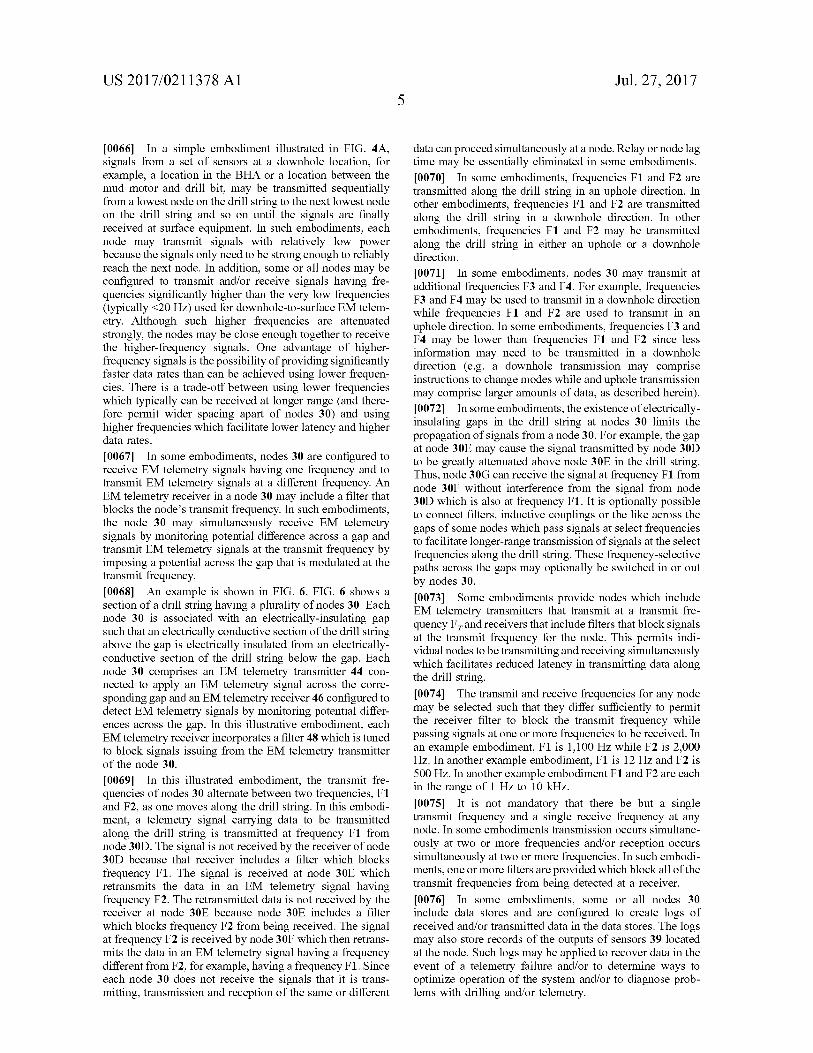
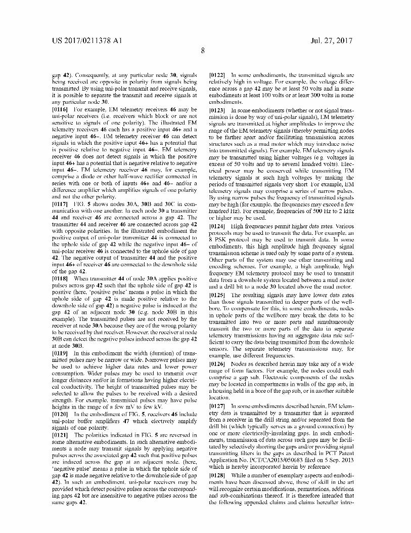
0066. In a simple embodiment illustrated in FIG. 4A, signals from a set of sensors at a downhole location, for example, a location in the BHA or a location between the mud motor and drill bit, may be transmitted sequentially from a lowest node on the drill string to the next lowest node on the drill String and so on until the signals are finally received at Surface equipment. In such embodiments, each node may transmit signals with relatively low power because the signals only need to be strong enough to reliably reach the next node. In addition, Some or all nodes may be configured to transmit and/or receive signals having fre quencies significantly higher than the very low frequencies (typically <20 Hz) used for downhole-to-surface EM telem etry. Although such higher frequencies are attenuated strongly, the nodes may be close enough together to receive the higher-frequency signals. One advantage of higher frequency signals is the possibility of providing significantly faster data rates than can be achieved using lower frequen cies. There is a trade-off between using lower frequencies which typically can be received at longer range (and there fore permit wider spacing apart of nodes 30) and using higher frequencies which facilitate lower latency and higher data rates.
0067. In some embodiments, nodes 30 are configured to receive EM telemetry signals having one frequency and to transmit EM telemetry signals at a different frequency. An EM telemetry receiver in a node 30 may include a filter that blocks the node's transmit frequency. In Such embodiments, the node 30 may simultaneously receive EM telemetry signals by monitoring potential difference across a gap and transmit EM telemetry signals at the transmit frequency by imposing a potential across the gap that is modulated at the transmit frequency. 0068 An example is shown in FIG. 6. FIG. 6 shows a section of a drill string having a plurality of nodes 30. Each node 30 is associated with an electrically-insulating gap such that an electrically conductive section of the drill string above the gap is electrically insulated from an electrically conductive section of the drill string below the gap. Each node 30 comprises an EM telemetry transmitter 44 con nected to apply an EM telemetry signal across the corre sponding gap and an EM telemetry receiver 46 configured to detect EM telemetry signals by monitoring potential differ ences across the gap. In this illustrative embodiment, each EM telemetry receiver incorporates a filter 48 which is tuned to block signals issuing from the EM telemetry transmitter of the node 30.
0069. In this illustrated embodiment, the transmit fre quencies of nodes 30 alternate between two frequencies, F1 and F2, as one moves along the drill String. In this embodi ment, a telemetry signal carrying data to be transmitted along the drill String is transmitted at frequency F1 from node 30D. The signal is not received by the receiver of node 30D because that receiver includes a filter which blocks frequency F1. The signal is received at node 30E which retransmits the data in an EM telemetry signal having frequency F2. The retransmitted data is not received by the receiver at node 30E because node 30E includes a filter which blocks frequency F2 from being received. The signal at frequency F2 is received by node 30F which then retrans mits the data in an EM telemetry signal having a frequency different from F2, for example, having a frequency F1. Since each node 30 does not receive the signals that it is trans mitting, transmission and reception of the same or different
Jul. 27, 2017
data can proceed simultaneously at a node. Relay or node lag time may be essentially eliminated in some embodiments. 0070. In some embodiments, frequencies F1 and F2 are transmitted along the drill String in an uphole direction. In other embodiments, frequencies F1 and F2 are transmitted along the drill String in a downhole direction. In other embodiments, frequencies F1 and F2 may be transmitted along the drill string in either an uphole or a downhole direction.
0071. In some embodiments, nodes 30 may transmit at additional frequencies F3 and F4. For example, frequencies F3 and F4 may be used to transmit in a downhole direction while frequencies F1 and F2 are used to transmit in an uphole direction. In some embodiments, frequencies F3 and F4 may be lower than frequencies F1 and F2 since less information may need to be transmitted in a downhole direction (e.g. a downhole transmission may comprise instructions to change modes while and uphole transmission may comprise larger amounts of data, as described herein). 0072. In some embodiments, the existence of electrically insulating gaps in the drill string at nodes 30 limits the propagation of signals from a node 30. For example, the gap at node 30E may cause the signal transmitted by node 30D to be greatly attenuated above node 30E in the drill string. Thus, node 30G can receive the signal at frequency F1 from node 30F without interference from the signal from node 30D which is also at frequency F1. It is optionally possible to connect filters, inductive couplings or the like across the gaps of some nodes which pass signals at select frequencies to facilitate longer-range transmission of signals at the select frequencies along the drill string. These frequency-selective paths across the gaps may optionally be switched in or out by nodes 30. 0073. Some embodiments provide nodes which include EM telemetry transmitters that transmit at a transmit fre quency F, and receivers that include filters that block signals at the transmit frequency for the node. This permits indi vidual nodes to be transmitting and receiving simultaneously which facilitates reduced latency in transmitting data along the drill string. 0074 The transmit and receive frequencies for any node may be selected such that they differ sufficiently to permit the receiver filter to block the transmit frequency while passing signals at one or more frequencies to be received. In an example embodiment, F1 is 1,100 Hz, while F2 is 2,000 Hz. In another example embodiment, F1 is 12 Hz, and F2 is 500 Hz. In another example embodiment F1 and F2 are each in the range of 1 Hz to 10 kHz. 0075. It is not mandatory that there be but a single transmit frequency and a single receive frequency at any node. In some embodiments transmission occurs simultane ously at two or more frequencies and/or reception occurs simultaneously at two or more frequencies. In Such embodi ments, one or more filters are provided which block all of the transmit frequencies from being detected at a receiver. 0076. In some embodiments, some or all nodes 30 include data stores and are configured to create logs of received and/or transmitted data in the data stores. The logs may also store records of the outputs of sensors 39 located at the node. Such logs may be applied to recover data in the event of a telemetry failure and/or to determine ways to optimize operation of the system and/or to diagnose prob lems with drilling and/or telemetry.

US 2017/021 1378 A1
0077 FIG. 4B shows another embodiment wherein EM telemetry data is transmitted directly to the surface from a location between a mud motor and a drill bit. 0078. The distance between the nodes and the range of the nodes may be adjusted based on various factors. These factors may include information about formations through which the wellbore will pass as well as the desired EM transmit frequency ranges for nodes 30. 0079. In some cases, drilling is being done through formations which include formations which are poor for EM telemetry transmissions. Such poor formations may, for example, have high electrical conductivity, thereby causing EM telemetry transmissions to be significantly attenuated. In some such cases the distances between the EM telemetry nodes may be selected Such that the nodes are close enough that even under the worst case scenario of the bad formation the signals emitted by one node can be picked up by the next node along the drill string. 0080. In some embodiments, the spacing between nodes 30 is on the order of a few hundred feet. For example, the nodes may be separated from their nearest-neighbour nodes by distances of 150 to 750 feet (about 50 metres to about 250 metres). In cases where it is known that the well bore penetrates a formation that is poor for EM telemetry (e.g. a formation with high electrical conductivity), nodes may be spaced more closely together in that part of the drill string that will be below the top of the poor formation and may be more widely spaced apart above that. 0081. In some embodiments, a node is coupled to the drill string after approximately every N drill String segments where N is, for example, a number in the range of about 3 to 30. The drill string segments may, for example, each be approximately 30 feet (10 metres) long. 0082 Optimizations can be achieved by providing con
trol over the nodes 30. Such control may be exercised from a central controller, which may be incorporated in Surface equipment or may be a downhole controller. In some alter native embodiments, some or all aspects of Such control are distributed among the nodes. Such control may be applied to adapt the network of nodes to various conditions that may develop. For example, the control may compensate for a node that has failed or a node whose batteries are running down or have run out. 0083. In such cases, a node below a failed node may be operated to transmit with increased power and/or a node uphole from a failed node may be tuned to receive signals from a node downhole from the failed node and/or a node uphole from the failed node may have its receiver gain increased. I0084 FIG. 4C illustrates an example where EM telem etry signals are relayed past a failed node 30X. 0085. The control may also be applied to conserve battery powerby reducing transmission power when possible and/or putting some nodes in Standby mode in portions of the drill string at which the range of one node is long enough that signals from the one node can be picked up from other non-adjacent nodes. I0086. In an example embodiment, nodes in all or part of the drill string have a low-power mode where every second node is in a standby mode and another mode in which all nodes are operating to relay data. The network may be Switched between these modes in response to a control signal, a measured signal quality (e.g. signal to noise ratio) at one or more modes or the like. If the signal to noise ratio
Jul. 27, 2017
(“SNR) is high the low-power mode may be selected. If SNR drops below a threshold the network may be placed in a mode where all nodes participate in relaying data. I0087 FIG. 4D illustrates an example case where some nodes in some parts of a drill String are in standby mode while nodes in other parts of the drill string are all used. In embodiments where nodes include sensors 39 a node may continue to log readings from any associated sensors 39 while it is in standby mode. I0088. In another application, a node may receive signals from a number of downhole nodes and may distinguish those signals by their frequencies or other signal character istics. In such cases, the signals transmitted by the adjacent node may be redundant. The node may transmit to the adjacent node a signal indicating that it is not currently needed. In response, the adjacent node may go into a standby mode. Other more Sophisticated Schemes are possible in which, in areas of a drill string where signals propagate for relatively long distances with reduced attenuation, interme diate nodes are placed into a standby mode such that their battery power is conserved. I0089 Conveniently, the EM telemetry transmitters and different ones of the nodes may be configured to transmit on different frequencies such that the signals from different nodes may be readily distinguished from one another. This can facilitate control over the nodes. The frequency used to transmit data rather than an ID number may be used to identify the source of the data. I0090. In some embodiments, the gain of EM telemetry receivers 34 in nodes 30 is variable. Variable gain may be used to increase gain when the receiver finds itself in an environment which is low in electromagnetic interference. Typically, at downhole locations which are significantly removed from the Surface, the quantity of electromagnetic interference is significantly decreased. Consequently, at such downhole locations the gain of an EM telemetry receiver can be increased significantly without Saturating the receiver with noise signals. Increasing the gain may be used to pick up signals from farther away along the drill string or to pick up signals which are initially transmitted with lower power. 0091. In some embodiments, power is conserved by increasing gain of a receiver 34 in a node 30 while one or both of decreasing the amplitude of a signal being received or transmitting the signal from a farther-away node. 0092. In some embodiments, the gain is increased gradu ally as the depth increases. This increase can optionally be based on a measure of pressure which, in general, increases with depth in the wellbore. For example, gain of an EM telemetry transceiver amplifier may be made to be directly proportional to the pressure detected by a pressure sensor. In other embodiments, depth is measured indirectly, for example, by the time taken to receive a mud pulse or by way of information regarding the depth of a node received from a separate controller or from Surface equipment. In some embodiments, a controller of a node measures a signal-to noise ratio of received signals and increases the gain if the signal-to-noise ratio is lower than a threshold. The controller may decrease the gain if the signal-to-noise ratio increases above a threshold. In some embodiments, the EM receiver gain may be increased to a value in the range of 10, 10°, or even higher. 0093. In some embodiments, EM telemetry transmission power of some nodes and receiver gain of other nodes which
US 2017/021 1378 A1
receive signals are coordinated. For example, as the depth below the surface increases, a node 30 may both increase the gain of the amplifier on its EM telemetry receiver while it decreases the power of its EM telemetry transmitter. This increase and decrease may be made automatically based on measurements of depth, which may be direct measurements or indirect measurements of depth and/or based on measure ments of signal-to-noise ratio in received signals. 0094 EM telemetry signals may be received at the sur face using conventional EM telemetry signal receivers or by means of a gap incorporated into the infrastructure of a drilling rig, for example, a gap incorporated into a quill or top drive or the like. 0095 Some nodes 30 may optionally include integrated mud pulsers. In cases where EM telemetry to a next node or to the surface is unreliable or not available because of a poor formation, data may still be transmitted by way of the mud pulser. 0096. A controller in a node 30 may analyze detected signals from other nodes. For example, the analysis may measure signal strength, signal-to-noise ratio, or the like. The signal analysis may also or in the alternative detect harmonics of the signal, for example by performing an FFT transformation to identify such harmonics. 0097. The node may transmit the analysis of the detected signal to the Surface and/or to a node from which the signal originated. This analysis information may be used to improve Some aspect of data transmission in the wellbore, for example, by setting transmit and/or receive parameters for some or all nodes 30. 0098. Such analysis and transmissions may be used to optimize performance of the network of nodes. For example, Suppose that a node 30 notices that a signal from another node known to be located 500 feet (about 160 metres) farther down the drill string is fading. Such fading is likely due to the nature of the formation through which the wellbore passes at the depth of the next node. The node that detects the fading signal may be configured to automatically boost its signal transmission when it gets to the same area at which the signal from the next node down the bore hole started to fade. The node may also transmit to other nodes above it signals indicating the quality of received signals. These informational signals may be processed at the Surface or at another location in order to determine areas within the wellbore at which nodes can be controlled to transmit with increased power (as well as or in the alternative other areas where nodes can be controlled to transmit with decreased power). 0099. In some embodiments, node 30 may send a number of parameters to one or more other nodes. These parameters may include, for example, downhole bore pressure (i.e. the hydrostatic pressure measured when no flow is occurring), transmission Voltage, transmission current, etc. Upon receiv ing downhole bore pressure, transmission Voltage and/or transmission current, a node 30 may record these values in a table that includes transmission Voltage, transmission current and downhole bore pressure values for different depths as well as, at least, the received signal strength at each pressure. This table of values may be continuously added to as drilling is continued. As more nodes 30 pass through a particular depth, the estimate of the transmission power at that depth may become more refined. Using the data in this table of values, a node may adjust its transmis sion power according to local downhole bore pressure. For
Jul. 27, 2017
example, in Some embodiments, when a node 30 approaches a pressure for which it already has data values, it may increase or decrease its transmission power accordingly. 0100. The foregoing discussion explains how a network of nodes 30 may be used to carry data from one or more downhole locations to Surface equipment. Such a network may also carry commands and/or other data from Surface equipment to nodes 30 and/or to other downhole systems in communication with one or more nodes 30. Thus, such a network may provide two-way data communication between:
0101 surface equipment and any node 30: 01.02 two nodes 30: 0.103 surface equipment and downhole systems in communication with one or more nodes 30:
0.104 different downhole systems in communication with nodes 30.
0105. Two-way communication to nodes 30 may, for example, be applied to control a specific node 30 or group of nodes 30 to change operating parameters and/or to change the frequency in which certain data is sent and/or to change the selection of data being sent from that node. Such two-way communication may also be applied to diagnose problems with a node and/or to control the node to solve and/or work around Such problems. 0106. It is not mandatory that all nodes use the same signal transmission formats. Different nodes may encode data differently depending on local conditions. For example, nodes close to the surface, where there is typically more electrical noise that tends to degrade EM telemetry trans missions, may encode signals using one or more of
01.07 different error correction codes: 0.108 different encoding schemes: 0109 different modulation schemes (e.g. FSK, BPSK, QPSK, etc.);
0110 different frequencies: 0.111 different protocols: 0112 different numbers of cycles/bit; 0113 etc.
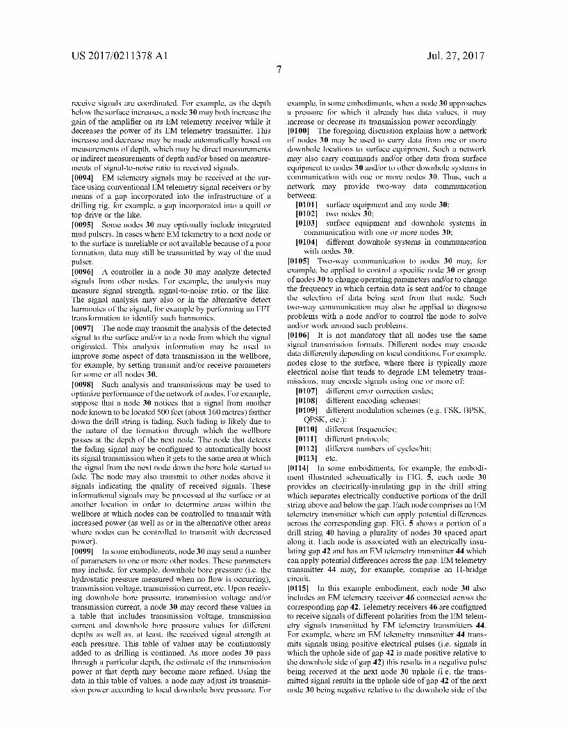
0114. In some embodiments, for example, the embodi ment illustrated schematically in FIG. 5, each node 30 provides an electrically-insulating gap in the drill string which separates electrically conductive portions of the drill string above and below the gap. Each node comprises an EM telemetry transmitter which can apply potential differences across the corresponding gap. FIG. 5 shows a portion of a drill string 40 having a plurality of nodes 30 spaced apart along it. Each node is associated with an electrically insu lating gap 42 and has an EM telemetry transmitter 44 which can apply potential differences across the gap. EM telemetry transmitter 44 may, for example, comprise an H-bridge circuit. 0.115. In this example embodiment, each node 30 also includes an EM telemetry receiver 46 connected across the corresponding gap 42. Telemetry receivers 46 are configured to receive signals of different polarities from the EM telem etry signals transmitted by EM telemetry transmitters 44. For example, where an EM telemetry transmitter 44 trans mits signals using positive electrical pulses (i.e. signals in which the uphole side of gap 42 is made positive relative to the downhole side of gap 42) this results in a negative pulse being received at the next node 30 uphole (i.e. the trans mitted signal results in the uphole side of gap 42 of the next node 30 being negative relative to the downhole side of the
US 2017/021 1378 A1
gap 42). Consequently, at any particular node 30, signals being received are opposite in polarity from signals being transmitted. By using uni-polar transmit and receive signals, it is possible to separate the transmit and receive signals at any particular node 30. 0116 For example, EM telemetry receivers 46 may be uni-polar receivers (i.e. receivers which block or are not sensitive to signals of one polarity). The illustrated EM telemetry receivers 46 each has a positive input 46+ and a negative input 46-. EM telemetry receiver 46 can detect signals in which the positive input 46+ has a potential that is positive relative to negative input 46-. EM telemetry receiver 46 does not detect signals in which the positive input 46+ has a potential that is negative relative to negative input 46-. EM telemetry receiver 46 may, for example, comprise a diode or other half-wave rectifier connected in series with one or both of inputs 46+ and 46- and/or a difference amplifier which amplifies signals of one polarity and not the other polarity. 0117 FIG. 5 shows nodes 30A, 30B and 30C in com munication with one another. In each node 30 a transmitter 44 and receiver 46 are connected across a gap 42. The transmitter 44 and receiver 46 are connected across gap 42 with opposite polarities. In the illustrated embodiment the positive output of uni-polar transmitter 44 is connected to the uphole side of gap 42 while the negative input 46- of uni-polar receiver 46 is connected to the uphole side of gap 42. The negative output of transmitter 44 and the positive input 46+ of receiver 46 are connected to the downhole side of the gap 42. 0118 When transmitter 44 of node 30A applies positive pulses across gap 42 such that the uphole side of gap 42 is positive (here, positive pulse means a pulse in which the uphole side of gap 42 is made positive relative to the downhole side of gap 42) a negative pulse is induced at the gap 42 of an adjacent node 30 (e.g. node 30B in this example). The transmitted pulses are not received by the receiver at node 30A because they are of the wrong polarity to be received by that receiver. However, the receiver at node 30B can detect the negative pulses induced across the gap 42 at node 30B.
0119. In this embodiment the width (duration) of trans mitted pulses may be narrow or wide. Narrower pulses may be used to achieve higher data rates and lower power consumption. Wider pulses may be used to transmit over longer distances and/or in formations having higher electri cal conductivity. The height of transmitted pulses may be selected to allow the pulses to be received with a desired strength. For example, transmitted pulses may have pulse heights in the range of a few mV to few kV. 0120. In the embodiment of FIG. 5, receivers 46 include uni-polar buffer amplifiers 47 which electively amplify signals of one polarity. 0121 The polarities indicated in FIG. 5 are reversed in some alternative embodiments. In such alternative embodi ments a node may transmit signals by applying negative pulses across the associated gap 42 Such that positive pulses are induced across the gap at an adjacent node. (here, negative pulse means a pulse in which the uphole side of gap 42 is made negative relative to the downhole side of gap 42). In Such an embodiment, uni-polar receivers may be provided which detect positive pulses across the correspond ing gaps 42 but are insensitive to negative pulses across the same gaps 42.
Jul. 27, 2017
0122. In some embodiments, the transmitted signals are relatively high in voltage. For example, the voltage differ ence across a gap 42 may be at least 50 volts and in some embodiments at least 100 volts or at least 300 volts in some embodiments.
I0123. In some embodiments (whether or not signal trans mission is done by way of uni-polar signals), EM telemetry signals are transmitted at higher amplitudes to improve the range of the EM telemetry signals (thereby permitting nodes to be farther apart and/or facilitating transmission across structures such as a mud motor which may introduce noise into transmitted signals). For example, EM telemetry signals may be transmitted using higher Voltages (e.g. Voltages in excess of 50 volts and up to several hundred volts). Elec trical power may be conserved while transmitting EM telemetry signals at Such high Voltages by making the periods of transmitted signals very short. For example, EM telemetry signals may comprise a series of narrow pulses. By using narrow pulses the frequency of transmitted signals may be high (for example, the frequencies may exceed a few hundred HZ). For example, frequencies of 500 Hz to 2 kHz or higher may be used. 0.124 High frequencies permit higher data rates. Various protocols may be used to transmit the data. For example, an 8 PSK protocol may be used to transmit data. In some embodiments, this high amplitude high frequency signal transmission scheme is used only by Some parts of a system. Other parts of the system may use other transmitting and encoding Schemes. For example, a high amplitude, high frequency EM telemetry protocol may be used to transmit data from a downhole system located between a mud motor and a drill bit to a node 30 located above the mud motor.
0.125. The resulting signals may have lower data rates than those signals transmitted in deeper parts of the well bore. To compensate for this, in some embodiments, nodes in uphole parts of the wellbore may break the data to be transmitted into two or more parts and simultaneously transmit the two or more parts of the data in separate telemetry transmissions having an aggregate data rate Suf ficient to carry the data being transmitted from the downhole sensors. The separate telemetry transmissions may, for example, use different frequencies. 0.126 Nodes as described herein may take any of a wide range of form factors. For example, the nodes could each comprise a gap Sub. Electronic components of the nodes may be located in compartments in walls of the gap Sub, in a housing held in a bore of the gap Sub, or in another Suitable location.
0127. In some embodiments described herein, EM telem etry data is transmitted by a transmitter that is separated from a receiver in the drill string and/or separated from the drill bit (which typically serves as a ground connection) by one or more electrically-insulating gaps. In Such embodi ments, transmission of data across Such gaps may be facili tated by selectively shorting the gaps and/or providing signal transmitting filters in the gaps as described in PCT Patent Application No. PCT/CA2013/050683 filed on 5 Sep. 2013 which is hereby incorporated herein by reference. I0128. While a number of exemplary aspects and embodi ments have been discussed above, those of skill in the art will recognize certain modifications, permutations, additions and sub-combinations thereof. It is therefore intended that the following appended claims and claims hereafter intro

US 2017/021 1378 A1
duced are interpreted to include all Such modifications, permutations, additions and Sub-combinations as are within their true spirit and scope.
Interpretation of Terms
0129. Unless the context clearly requires otherwise, throughout the description and the claims:
0.130 "comprise”, “comprising, and the like are to be construed in an inclusive sense, as opposed to an exclusive or exhaustive sense; that is to say, in the sense of “including, but not limited to”.
I0131) “connected”, “coupled, or any variant thereof, means any connection or coupling, either direct or indirect, between two or more elements; the coupling or connection between the elements can be physical, logical, or a combination thereof.
(0132 “herein”, “above”, “below, and words of simi lar import, when used to describe this specification shall refer to this specification as a whole and not to any particular portions of this specification.
0.133 'or', in reference to a list of two or more items, covers all of the following interpretations of the word: any of the items in the list, all of the items in the list, and any combination of the items in the list.
0.134 the singular forms “a”, “an', and “the also include the meaning of any appropriate plural forms.
0135 Words that indicate directions such as “vertical'. “transverse”, “horizontal”, “upward”, “downward”, “for ward”, “backward”, “inward”, “outward”, “vertical”, “trans verse”, “left”, “right”, “front”, “back”,” “top”, “bottom', “below”, “above”, “under', and the like, used in this description and any accompanying claims (where present) depend on the specific orientation of the apparatus described and illustrated. The subject matter described herein may assume various alternative orientations. Accordingly, these directional terms are not strictly defined and should not be interpreted narrowly. 0136. Where a component (e.g. a circuit, module, assem
bly, device, drill string component, drill rig system, etc.) is referred to above, unless otherwise indicated, reference to that component (including a reference to a “means’) should be interpreted as including as equivalents of that component any component which performs the function of the described component (i.e., that is functionally equivalent), including components which are not structurally equivalent to the disclosed structure which performs the function in the illustrated exemplary embodiments of the invention. 0.137 Specific examples of systems, methods and appa ratus have been described herein for purposes of illustration. These are only examples. The technology provided herein can be applied to systems other than the example systems described above. Many alterations, modifications, additions, omissions and permutations are possible within the practice of this invention. This invention includes variations on described embodiments that would be apparent to the skilled addressee, including variations obtained by: replacing fea tures, elements and/or acts with equivalent features, ele ments and/or acts; mixing and matching of features, ele ments and/or acts from different embodiments; combining features, elements and/or acts from embodiments as described herein with features, elements and/or acts of other technology; and/or omitting combining features, elements and/or acts from described embodiments.
Jul. 27, 2017
0.138. It is therefore intended that the following appended claims and claims hereafter introduced are interpreted to include all Such modifications, permutations, additions, omissions and Sub-combinations as may reasonably be inferred. The scope of the claims should not be limited by the preferred embodiments set forth in the examples, but should be given the broadest interpretation consistent with the description as a whole. 0.139. Some embodiments provide an improved down hole electronic system data network in which a plurality of nodes are attached to a drill string to relay information to the Surface. The nodes relay information to surface equipment using relatively high frequency EM transmissions, generally greater than 20 Hz, providing faster data rates and lower latency. 0140. The downhole data network node of certain embodiments of the present invention comprises an EM telemetry transmitter, EM telemetry receiver, a controller and an electrically-insulating gap. The EM telemetry receiver is configured to monitor a potential difference across the gap and to communicate changes in the potential difference to the controller. The EM telemetry transmitter is connected to the controller and configured to apply a Voltage signal across the gap. In one embodiment, when the EM telemetry receiver detects a potential difference across the gap, signifying a data transmission, the EM telemetry receiver provides the data transmission to the controller which in turn causes the EM telemetry transmitter to trans mit the data transmission to an adjacent node or Surface equipment.
1. A method for transmitting data along a drill String, the method comprising:
transmitting a first signal from a first node based on a first transmission setting while the first node is located at a first depth;
measuring an aspect of the first signal at a second node: determining a second transmission setting based on the
measurement of the measured aspect of the first signal; advancing the drill string so that the second node is
proximate to the first depth; and transmitting a second signal at the second transmission
setting from the second node while the second node is located proximate to the first depth.
2. A method according to claim 1 wherein the aspect comprises a signal strength of the first signal at the second node.
3. A method according to claim 1 wherein the aspect comprises a signal-to-noise ratio of the first signal at the second node.
4. A method according to claim 1 wherein the aspect comprises a harmonic frequency of the first signal.
5. A method according to claim 1 comprising configuring the first node to transmit a signal based on the second transmission setting.
6. A method according to claim 1 wherein the setting comprises a frequency setting.
7. A method according to claim 1 wherein the setting comprises an amplitude setting.
8. A method according to claim 1 wherein the setting comprises a gain setting.
9. A method according to claim 1 comprising transmitting signals from the first node at a first frequency and receiving signals at the first node at a second frequency, wherein the first frequency is different from the second frequency.

US 2017/021 1378 A1
10. A method according to claim 9 comprising transmit ting signals from the second node at the second frequency and receiving signals at the second node at the first fre quency.
11. A method according to claim 9 comprising filtering out the first frequency at a receiver of the first node.
12. A method according to claim 9 comprising filtering out a plurality of frequencies including the first frequency at a receiver of the first node.
13. A method according to claim 9 wherein filtering out the first frequency at a receiver of the first node comprises using harmonic separation.
14. A method according to claim 1 comprising transmit ting signals from the first node at a first polarity and transmitting signals at the second node at a second polarity, the first polarity opposing the second polarity.
15. A method according to claim 1 wherein transmitting a second signal at the second transmission setting comprises decoding and buffering the first signal.
16. A method according to claim 1 wherein transmitting a second signal at the second transmission setting comprises adding additional data to the first signal.
17. A method according to claim 16 wherein adding additional data to the first signal comprises providing a node identifier with the additional data.
18. A method according to claim 17 wherein the node identifier comprises a time stamp.
19. A method according to claim 17 wherein the node identifier comprises an incremental count.
20. A method according to claim 1 wherein the first node and the second node each comprise an electrically insulating gap and an electromagnetic telemetry transceiver.
21. A method according to claim 9 wherein transmitting signals at the first and second frequencies comprises trans mitting signals in a first direction.
22. A method according to claim 21 comprising transmit ting signals in a second direction using a third and fourth frequency wherein the first, second, third and fourth fre quencies are different from one another and the first direc tion is opposite the second direction.
23. A method according to claim 22 wherein each of the third and fourth frequencies are lower than each of the first and second frequencies.
24. A method according to claim 1 comprising increasing a gain value of the second transmission setting with depth.
25. A method according to claim 1 comprising decreasing a power value of the second transmission setting with depth.
26. A system for transmitting data along a drill String, the system comprising:
a first node operable to transmit signals positioned along the drill string, the first node in communication with one or more sensors, the first node configured to transmit a first signal based on a first transmission Setting:
a second node operable to transmit signals positioned along the drill String and spaced apart from the first node, the second node in communication with the first node, the second node configured to measure an aspect of a first signal transmitted by the first node while the first node is located at a first depth; and
a controller configured to determine a second transmis sion setting based on the aspect of the first signal measured by the second node:
Jul. 27, 2017
wherein the second node is configured to transmit a second signal at the second transmission setting while the second node is located proximate to the first depth.
27. A system according to claim 26 wherein the first node is configured to transmit signals at a first frequency and receive signals at a second frequency, wherein the first frequency is different from the second frequency.
28. A system according to claim 27 wherein the second node is configured to transmit signals at the second fre quency and receive signals at the first frequency.
29. A system according to claim 28 wherein the first node is configured to filter out at least the first frequency at a receiver of the first node.
30. A system according to claim 29 wherein the first node comprises a filter connected to block at least the first frequency from reaching a receiver of the first node.
31. A system according to claim 30 wherein blocking at least the first frequency from reaching a receiver of the first node comprises using harmonic separation.
32. A system according to claim 26 wherein the first node is configured to transmit signals at a first polarity and the second node is configured to transmit signals at a second polarity, the first polarity opposing the second polarity.
33. A method for data telemetry from a downhole loca tion, the method comprising:
providing a plurality of telemetry relay devices at loca tions spaced apart along a drill string, each of the telemetry relay devices comprising an electromagnetic telemetry signal receiver and an electromagnetic telem etry signal transmitter,
moving the drill string in a wellbore; identifying a first region of the wellbore in which elec
tromagnetic telemetry transmissions are attenuated more strongly and a second region of the wellbore in which electromagnetic telemetry transmissions are attenuated less strongly;
passing data up the drill string by sequentially relaying the data by electromagnetic telemetry from one of the relay devices to another, and,
boosting the signal transmission of the telemetry relay devices while those telemetry relay devices are in the first region, and based on a signal detected from the telemetry relay devices in the first region, automatically inhibiting operation of some of the telemetry relay devices while those telemetry relay devices are in the second region.
34. A method for data telemetry from a downhole loca tion, the method comprising:
providing a drill String in a wellbore, the wellbore passing through formations such that a range of electromag netic telemetry transmissions varies as a function of depth in the wellbore;
passing data from a downhole location to the Surface using a plurality of telemetry relay devices between the downhole location and the Surface;
identifying first and second non-adjacent ones of the telemetry relay devices such that the second one of the telemetry relay devices is within the range for electro magnetic telemetry transmissions corresponding to the location of the first one or the telemetry relay devices: and,
inhibiting operation of one or more of the telemetry relay devices between the first and second ones of the telemetry relay devices wherein inhibiting operation of

US 2017/021 1378 A1
the one or more of the telemetry relay devices com prises placing the node in power-conserving standby mode.
35. A method according to claim 34 comprising advanc ing the drill string until the range of electromagnetic telem etry transmissions corresponding to the location of the first one of the telemetry relay devices is reduced and then activating one or more of the one or more electromagnetic telemetry relay devices between the first and second ones of the electromagnetic telemetry relay devices.
36. A method according to claim 35 comprising monitor ing the range of the electromagnetic telemetry signals by transmitting electromagnetic telemetry signals from a trans mitter on the drill string and receiving the electromagnetic telemetry signals transmitted by the transmitter at a plurality of the electromagnetic telemetry relay devices.
37. A method according to claim 36 wherein the trans mitter is a transmitter of one of the electromagnetic telem etry relay devices.
38. A system for transmitting data along a drill String, the system comprising:
a first plurality of nodes operable to transmit signals positioned along the drill string, each one of the first plurality of nodes in communication with one or more sensors and configured to transmit a signal based on a transmission setting for the node:
a second plurality of nodes operable to transmit signals positioned along the drill string, wherein each one of the second plurality of nodes is in communication with a corresponding one of the first plurality of nodes and is configured to measure an aspect of the signal trans mitted by the corresponding one of the first plurality of nodes; and
Jul. 27, 2017
a controller configured to determine a transmission setting for each one of the second plurality of nodes based on the aspect of the signal measured by the node,
wherein for each one of the second plurality of nodes, the node is configured to transmit a signal at the transmis sion setting for the node while the node is located proximate to a depth of the corresponding one of the first plurality of nodes when an aspect of the signal transmitted therefrom was measured.
39. A system according to claim 38 wherein the first plurality of nodes is configured to transmit signals at a first frequency and receive signals at a second frequency, wherein the first frequency is different from the second frequency.
40. A system according to claim 39 wherein the second plurality of nodes is configured to transmit signals at the second frequency and receive signals at the first frequency.
41. A system according to claim 40 wherein each one of the first plurality of nodes is configured to filter out at least the first frequency at a receiver of the node.
42. A system according to claim 41 wherein each one of the first plurality of nodes comprises a filter connected to block at least the first frequency from reaching a receiver of the node.
43. A system according to claim 42 wherein blocking at least the first frequency from reaching a receiver of the node comprises using harmonic separation.
44. A system according to claim 43 wherein the first plurality of nodes is configured to transmit signals at a first polarity and the second plurality of nodes is configured to transmit signals at a second polarity, the first polarity oppos ing the second polarity.
k k k k k