Embed Size (px)
Citation preview
N91-22140
E m Mm m_m_K_S.'r_l_
RPbert L. Forward
Forward Unlimited
Malibu, California 90265-7783 USA
The status of some exotic physical phenomena and unoonventional spacecraft
concepts that might produce breakthroughs in power and propulsion in the 21st
Century are reviewed. The subjects covered include: electric, riLe:learfission,
nuclear fusion, antimatter, high energy density materials, metallic hydrogen,
laser thermal, solar thermal, solar sail, magnetic sail_ and tether propulsion.
Chemical rockets have opened up space, landed humans on the Moon, putrobotic landers on Venus and Mars, and sent flyby probes past all the major
planets and moons in the solar system. All this despite the fact that any
physicist can prove than any known chemical fuel doesn't have enough energy
oontent to raise even itself into orbit, much less take any payload with it.
Propulsion engineers proved the physicists wrong by designing multiple stagevehicles with extremely high mass ratios ti_at reached 622:1 for the Saturn V
,Don rocket liftoff mass vs. the capsule mass that parachuted back to the: Earth's surface.
If the United States decides it _ants to construct a space defense, set up
;. a lu"ar base, or explore Mars, then chemical rockets can do those jobs. Butbecause of the relatively low specific impulse of chemical propellants, and the
high overall mass ratios they imply for these difficult missions, the cost for
acosmplishing these tasks will be so high it is very likely that the United
States will decide not to do the mission at all. If we are going to return to
the Moon, exl_lore Mars, and open u_ the solar system to rapid, economicaltravel, we need to find a method of propulsion that is an improveme, t over
standard chemical rocket propulsion. That is the goal of that amorphous field
of aerospace engineering called "advanced space propulsion".
_EL_%R _IGS
If the public can be sold on the idea of using nuclear propulsion for
future space missions--fine. Proceed using that technology and ignore the rest
of this paper. I suspect, however, that despite its real lack of danger and
its great savings in cost and time, the nuclear rocket will not be a
politically viable method of space travel. I will therefore wr ite the rest of
this paper and I encourage you to read it.
11
.-%
..J
1991012826-014
am/ear_rml Pr_ml._.Nuclear thermal propulsion is an advanced propulsion teclmology capable of
producing thrust-to-weights greater than unity at high specific impulses of
typically 825 seconds (nearly twice that of liquid-oxygen/liquid-hydrogen).Nuclear rockets were demonstrated to be feasible in the ROVER and NERVA solid
core fission reactor test programs from 1959 to 1972, but unfortunately they
were killed for political and budgetary reasons before they ever got off theground. A summary of nuclear thermal rocket development and testing experienceis covered in reference I.
am_. Pzo_mlskmSince the nuclear fusion process typically cop,,erts three times as much mass to
energy as the nuclear fission process, it has long been recognized that fusionfuels are much more energetic than fisslen _hels. Fusion propulsion is a
wonderful idea, but its time has yet to co_. Researchers still have notdemonstrated a self-sustained eontrolled fus_or reaction on the ground, and the
reactor designs presently being funded by t_e Department of _ergy are more
suitable for massive power plants than lightweight rocket engines. That
doesn't stop the advanced propulsion advocates from looking at new fusion
propulsion concepts and designing new, lightweight fusion rockets. Wheth_.rthese lightweight designs can ever be made self-sustaining is problematic,considering all the work put in on their larger power plant cousins.
Robert W. Bussard at EMC 2 has proposed (ref. 2) a low thrust fusion
electric propulsion system that uses his Riggatron compact tokamak fusionreactor design designed operate on the difficult D-D fusion reaction. This
reaction produces tritium, helium-3, and a fast neutron. The neutrons escape
to space, while the hot (10-40 keV) tritium and helium-3 plasma is extracted at
30 atm pressure and mixed with a large amount of hydrogen gas diluent
propellant to produce a high specific impulse exhaust. Bussard alSol_peculgteson an "electrostatic fusion propulsion" system using the reaction p+ B-_3 erie.
In principle, the fusion product energy can be converted directly £nto electric
power by causing the charged helium ions to expand against an electric field.This would result in a fusion-electric propulsion option with high specific
impulse and high thrust.
V.E. "Bill" Haloulakas at McDonnell-Douglas and Bob Bourque at General
Atomics carried out an Air Force Astronautics Laboratory sponsored study
(ref. 3) of a D-3He fusion rocket using pulsed translating compact toroids thatborrows from the DoE spheromak program. Again, thermal energy from the plasma
heats a hydrogen propellant to obtain the optimum specific impulse.
In a combination of two technologies, Gerald Smith of Penn State has shown
that antiprotons impinging on uranium atoms create fission nearly 100% of the
time, releasing 180 MeV of fission fragment energy in the target. Under JPL
sponsorship, Smith is now studying the use of small _ounts of antimatter to
trigger fission in the uranium shell of a pellet, which in turn will triggerfusion in the D-T mixture in the center of the pellet.
12
• __._ . _,,2, .............
IIII Ill I IIIII ........... 199101Zt Zt, U'l o- --- -" """"-"" '-
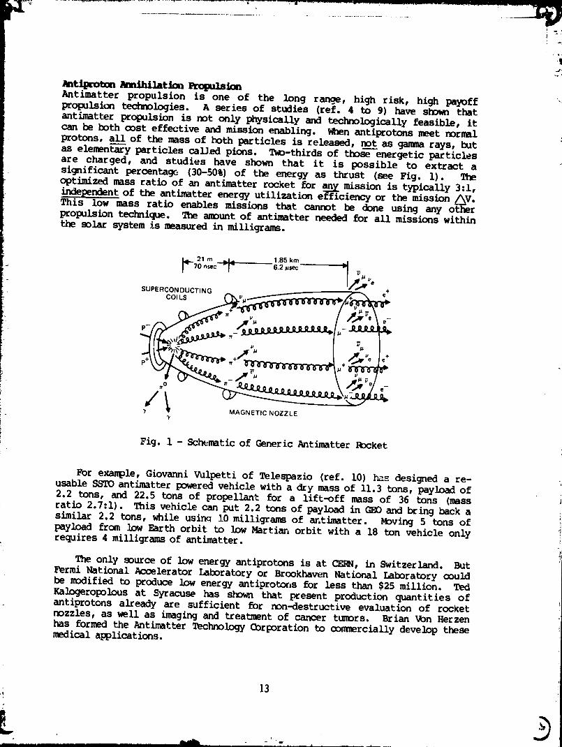
•.t_ Pa.ihnat_ _io.Antimatter propulsion is one of the long ran._, high risk, high payoffpropulsion technologies. A series of studies (ref. 4 to 9) have shown thatantimatter propulsion is not only physically and technologically feasible, itcan be both cost effective and mission enabling. When antlprotons meet normalprotons, all of the mass of both particles is released, not as gamma rays, butas elementar---yparticles called pions. Twp-thirds of tho_--energeticparticlesare charged, and studies have shown that it is possible to extract asignificant peroentage (30-50%) of the energy as thrust (see Fig. I). Theoptimized mass ratio of an antimatter rocket for any mission is typically 3:1,independentof the antimatter energy utilization efficiency or the mission /_V.This low mass ratio enables missions that cannot be done using any otherpropulsion technique. The amount of antimatter needed for all missions withinthe solar system is measured in milligrams.
_. 21m i 1.85km _i/_J_'
70 nsec _ = 6.2_$ecue
SUPERCON OUCTING + eCOILS (_Vl_/ /__
(]_'_'l_ rr V / _'_'e _ e-
• _+ +
f ........"""•_ w MAGNETICNOZZLE
Fig. 1 - Schematic of Generic Antimatter Rocket
For example, Giovanni Vulpetti of _le_zio (ref. I0) has designed a re-usable SSTO antimatterpowered vehicle with a dry mass of II.3 tons, payload of2.2 tons, and 22.5 tons of propellant for a lift-off mass of 36 tons (massratio 2.7:1). This vehicle can put 2.2 tons of payload in GEO and bring back asimilar 2.2 tons, while usinq 10 milligrams of antimatter. Moving 5 tons ofpayload from low Earth orbit to low Martian orbit with a 18 ton vehicle onlyrequires 4 milligramsof antimatter.
The only source of low energy antiprotons is at CF_, in Switzerland. ButFermi National Acuelerator Laboratory or Brookhaven National Laboratory couldbe modified to produce low energy antiprotons for less than $25 million. TedKalogeropolous at Syracuse has sbo_ that present production quantities ofantiprotons already are sufficient for non-destructive evaluation of rocketnozzles, as _ll as imaging and treatment of cancer tumors. Brian Von Herzenhas formed the Antimatter Technology Corporation to commercially develop thesemedical applications.
13
L b
The RAND (brporation has sponsored two Antiproton Science and Technology
workshops (ref. ii) that found no showstr,ppers to antimatter propulsion, but
determined that producing adequate quantities (grams per year) would requiretwo successive generations of dedicated antiproton production facilities, a
pilot plant to prove eoonomic feasibility, followed by a large production
plant. Realistically, this will take 30 years and 30 billion dollars, but itoould save many hundreds of billions in the cDst of future national spaceinitiatives.
The present experimental effort in the field is concentrated on the captureand storage problem. Gerald Gabrielse of Harvard led an international team to
CERN, captured 60,000 antiprotons in a cryogenic, ultrahigh vacuum
electromagnetic trap no larger than a demitasse cup, and kept them trapped for
50 hours (ref. 12). The next step is adding positrons and making antihydrogen.The Air Force Astronautics Lab is ]oo):ing into the growth of charged
antihydrogen cluster ions as a method of condensing the antihydrogen whilemaintaining it in a trap. Under JPL sponsorship, George Seidel at Brown
University is solving the problems of levitating milligram sized balls of
antihydrogen ice. Since the electromagnetic and mechanical properties ofhydrogen and antihydrogen are the same, the research is being carried out usingnormal hydrogen.
Antimatter rockets are a form of nuclear rocket. Although they emitinsignificant amounts of neutrons, and the engines do not present a long term
radiation hazard as do nuclear thermal rocket engines, they do emit gamma rays
when operating, and require proper shielding and stand-off distanceprecautions. Unfortunately, the word "antimatter" still evokes raised
eyebrows, mental images of Star Trek, and stifled giggles from upper leveldecision makers in the advanced propulsion branches of NASA and the Air Force.
If they would read the scientific literature and be willing to consider
technologies other than those that will produce results during their short timein office, they would find a new propulsion technology that could open up the
solar system.
_3_IC C_CAL
High Energy Density Materials (HE_4) is the new Holy Grail of the chemicalpropulsion community. All the chemical elements are known, and nearly all the
possible combinations of those elements into molecular compounds are known.Over the centuries since the Chinese invented gunpowder, there has been a !
continuing life-or-death motivation to find the most energetic of those
compounds for use in propelling projectiles and rockets. To date, the most iienergetic fuel we have (that isn't deadly poisonous) is liquid-oxygen/liquid-
hydrogen, which produces a maximum specific impulse of 500 seconds. Some wouldsay there are no new chemical propellants to be found. The goal of the HEDM
program is to somehow find a new chemical material with both a high energydensity and a low molecular weight.
14
allii I I II I II1| " "-] ..... nnl , - " _ ........
1991012826-017
The major H_3M effort in the United States is at the Applied ._esearch In j_ergy Storage (ARIES) Office at the Air Force Astronautics Laboratory, withanother large effort in basic research being funded out of the Air Force Office
of Scientific Research. A 1986 outgrowth of Project Forecast If, the Air Force
H_]M program is putting more t_m $5 million a year into 50 R&D projects aroundthe world. They hold annual contractors conferences where the results of the
previous year are shared with t_e research community (ref. 13-15). There are a ._number of ways to increase the energy density of a fuel: Add light metals asatoms or small clusters, trap the energy of an excited electronic or
vibrational state, force molecules to form highly strained bonds, and condensethe material into a denser form.
Metastable helium fuel, made of electronically excited helium atoms (theeasily-formed active ingredient in a helium-neon laser), has a projected
specific impulse of 3100 sec)nds. The practical lifetime of metastable helium
is less than one second, although theory projects an ideal lifetime of eight
years. Early in the HEDM effort, Jonas Zmuidzinas of JPL investigated
i variations in, lying metastable helium molecules and solid metastable heliummetal, with no positive results. No active research in this area is known ofat this time.
Tetrahydrogen (an excited state molecule with four hydrogen atoms in a_ tetrahedron-shaped molecule) initially also looked promising, but detailed
calculations on large computers showed it had a rapid-acting decay channel,
verifying why it is not found in nature. The study of this system has led to 1
other candidates, such as a-N202 (asymmetric nitrous peroxide), Li3H, FN3, andB2Be 2. Theoretically, B2Be2 has a heat of formation of 238 kcal/Rple and when
unim_lecularly decomposed gives a specific impulse of over 600 seconds. FN3has been prepared, is stable at low temperatures, and in addition to being an
interesting monopropellant, also seems to have applications as a shortwagelength chemical laser fuel and a high explosive!
Spin-polarized atomic hydrogen with a potential specific impulse of 2100seconds has been produced in the laboratory by Daniel Kleppnet- of MIT in
quantities large erK)ugh to cause damaging explosions in cryogenic glassware,but the lifetime of the atoms decreases drastically with density, due to an
increase in three-body reoombination collisions. Unless a way is found aroundthis problem, it will not produce a usable fuel.
Unconventional molecules with "strained" bonds, such as variations on
cubane (a cube made of carbon atoms with 90 degree bonds instead of the normal
180 degree linear carbon bonds) are being studied, both by supercomputers and
test tube. Something may come of this research, but the increase in specific
i_pulse over that of LOX-hydrogen will not be great.
Metallic hydrogen, a dense form of atomic hydrogen with a specific impulseof 1700 seconds and a density of 1.15 g/cc (compared to 0.07 g/cc for liquid
molecular hydrogen), looks promising. H.K. Mac) and R.J. Hemley at Carnegie
Institution have used diamond anvil presses to apply pressures up to 300 GPa(3 Mbar) to micrometer sized samples of molecular hydrogen, trying to turn it
into a superconducting metal. They have reported darkening of the sample
(ref. 16), indicating absorption of light, but further work is needed to
15
' 1991012826-018
determine if it is a partially conducting form of molecular hydrogen or thedesired metallic atomic hydrogen. Their darkened sample returned to its normal
state when the pressure was released. Similar work, sponsored by the AFAstronautics Laboratory, is also underway by Isaac Silvera at Harvard.
Even if metallic hydrogen can be formed at high pressure, no one knows what
will happen when the pressure is released. Some theorists predict it will he,J'
metastable, and stay in the dense metallic form. (Diampnd is a metastable form
of graphite formed at high pressure but stable at low pressure.) Other
theorists predict it will rapidly revert to the molecular form of hydrogen. If
it remains stable at some pressure substantially less than that necessary forform it, there is a lot of engineering to be done to move from micrometer sized
hatches to continuous flow production of tons per day, but with a specific
impulse of 1700 seconds, metallic hydrogen will do everything for space travelthat beamed laser power, nuclear thermal, and antimatter rockets could do, andbe a lot cheaper and safer.
_netic Engines and t_zz_esNearly all advanced high thrust, high specific impulse rocket concepts that usehigh power electromagnetic thrustors, metallic hydrogen or metastable helium
fuels, beamed laser or microwave power, fission, fusion, or antimatter energy;in fact, any rocket technique that produces thermalized propellant exhausts
with specific impulses above 1500 seconds, all have the same problem. The highenergy exhaust from any of these processes will produce a blazing plasma that
will melt the reaction chamber and nozzle if they are made out of ordinaryrefractory materials. One solution is to make the. enginc and nozzle out of
magnetic fields. There are two ongoing experimental research efforts onmagnetic nozzles to handle these high density, high temperature plasmas. One
by Joel Sercel at Caltech sponsored by JPL, and one by Ted Yang and astronautFranklin Chang-Diaz at MIT sponsored by JPL and AFOSR. Some recent studies
(ref. 17), however, have uncovered a potential problem. Plasma constrained toan axially symmetric flow by an axially symmetric magnetic field will
experience a resistive drag as it tries to axially detach itself from theradially diverging magnetic field lines. This drag will be transmitted to the
vehicle through the magnetic field coils. Research in the area of magneticfield assisted reaction chambers and exhaust nozzles needs to be continued and
expanded. Otherwise, we may find that we have developed a new propulsionenergy concept without having the means to convert that propulsion energy intopropulsive thrust.
• LIVING _ ROCEETS A_) LIKING IT
If in the next few years space nuclear propulsion proves to be politicallyunpalatable, and the HE3]M programs do not produce a new chemical fuel with a
significant increase in specific impulse over liquid-oxygen/liquid-hydrogen,
then those in charge of the future of this nation's space programs are going to
face a harsh reality. Our future in space can only be assured if we give up
our dependence on self-contained rockets. A rocket not only has to carry itspayload, hut it must also carry its engine, its energy source, and its reaction
l_ass. If we want rapid, economical space travel within the solar system, wemust develop and demonstrate new technologies that are not rockets and are not
16
I iii iii i / ii I ii -- ii _ _-- , i i i
1991012826-019
Ilimited by the exponential mass growth of the rocket equation. Fortunately, Ithere are plenty of car_idates. Some examples are: beamed power laserpropulsion, solar tb_r_l propulsion, solar sails, magnetic sails, and tethers. 2
Some do not carry their engine, some do not carry their energy source, some do
not carry their reaction mass, and some do without all three. :]
Beamed power laser propulsion received a big boost in the past few years.
Since 1987, SDIO has sponsored a tw_ million dollar per year research program
on laser propulsion managed through Lawrence Liverm_re National Laboratory(LLNL). _bst of the effort has focussed on the nozzle-less planar thruster
originally suggested by Arthur Kantrowitz (ref. 18). The payload sits on a
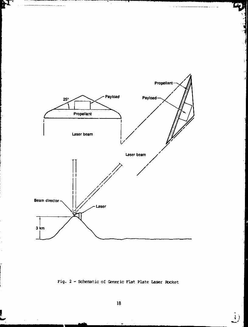
solid block of a_lative propellant such as plastic or _ater ice (see Fig. 2).An "evaporation" laser pulse ablates a few-micrometer-thick layer of
propellaLnt, forming a thin layer of gas. A second laser pulse then "explodes"
this gas layer, producing thrust on the plate of propellant. The process takesa few microseconds and is repeated at 100-1000 Hz rates. An important feature
is that the explosive expansion takes place so close to the plate of propellantthat no nozzle is needed. The resultant thrust is normal to the plate and
independent of the direction of the incident laser light, allowing the vehicle
to fly at an angle to the laser beam. The vehicle can therefore transitioninto a near-circular orbit without requiring an apogee kick mDtor. The vehicle
is steered from the ground by moving the laser beam off the center of the base
plate, and so does not need an onboard guidance system. The payload sizedepends on the laser power ; 20 MW can launch a 150 kg vehicle carrying a 20 kg
payload. Higher powers can launch proportionately larger payloads. Peakaccelerations are corn@arable to those of chemical rockets.
Jordin Kate of LLNL (ref. 19) reports that experiments have now been
conducted at several industry and government laboratories. The double-pulsethruster concept works, producing high thrust efficiency and specific impulses
up to 800 seconds. The actual thrust efficiencies obtained to date are onlyabout 10%. The LLNL-SD!O program had hoped to use the induction linac fee
electron laser (FEL) proposed by _ for SDIO tests at White Sands to do high-power suborbital (and possibly orbital) launch tests. SDIO has now decided to
build a lower power RF-linac FEL, which puts out a poor pulse format for pulsedlaser propulsion.
Another approach to laser propulsion is to absorb laser light in a plasma
"flame" sustained by laser light focused in the center of a flowing stream of
propellant gas. Thrust levels as high as 10,000 N with specific impulses ofI000 seoonds appear achievable using hydrogen as the propellant gas. Dennis
Keefer and others of University of Tennessee, working with a 1 kW CW CO 2 laser,
have reported an absorption efficiency of 86% and a thermal efficienc] of 38%
in an argon plasma at 2.5 arm. They repeated the experiments using an RF-linacfree-electron-laser that produces a 0.i ms burst of i0 ps pulses separated by
46 ns. These short pulses ignited the argon gas and formed a plasma that
absorbed 92% of the laser power (ref. 20). Hydrogen and nitrogen gas did notignite at the pulsed laser powers available.
17
, 1_
..... 1991012826-020
//1Propella
/
/
r k '' Propellant -_'_ /
, /f ,Laserbeam I /
I/
/
Laserbeam /
//_'/
er
Fig. 2 - Schematic of Generic Flat Plate Laser RDcket
18
................. III " ' _ ............... llll ",, , ....
1991012826-021
Herman Krier and Jyotirmoy Mazumder of University of Illinois at Urbana-
Champaign have recently achieved a very promising 81% absorption efficiency anda 72% thermal efficiency with 7 kW of 002 laser power into a 2.5 arm hydrogen
plasma flowing at 10.3 m/s. Leik Myrabo of Rensselaer Polytech (ref. 21) is
investigating a 300 kg launch mass 5ightcLaft Technology Demonstrator thatrides up a laser beam from a 100 MW-class ground-based free-electron-laser.
The laser power heats scooped air in the atmosphere and onboard _rope_lant in
space, pushing the 124 kg spacecraft into orbit.
Laser powers as low as 1 MW would useful for LEO-C4_O orbit raising withoutrelay optics, i0-I00 MW lasers can launch small payloads from the ground.
With up to 100 launches a d_y, a 20 MW, 20 kg payload launcher could place
several hundred tons in orbit _._ year. Low gigawatt lasers could launch
multiton spacecraft with the same ease that present multigigawatt chemicalrockets do. Laser rockets will have better payload fractions since the heavy
power plant is left on the ground and the higher specific impulse results inlower propellant fractions. Although gigawatt lasers are not off-the-shelf
items, there is no doubt they could be built if the need was strong enough.
One method of obtaining power and propulsion in space is to use large
inflated concentrating mirrors to gather and focus solar energy onto a light-
absorber which converts the solar energy into thermal energy. The thermal
energy can be used to operate a heat engine to produce electricity, or it canbe used to heat propellant (typically hydrogen) which can then exhausted to
produce thrust. The major effort in this area is being sponsored by the Air
Force Astronautics Laboratory (AFAL). Their program (ref.22) has proceeded
through the research phase and is now directed toward flight tests in the late1990s. In the mid 1980s, Bocketdyne built a small thrustor for AFAL consisting
of a cylindrical cavity lined with rhenium tubing through which flowed hydrogengas. Sunlight focused into the cavity from a 25 kW solar facility at AFAL
produced 4.45 N of thrust at a measured specific impulse of 820 seconds.
AFAL is now investigating two advanced forms of thrustors. One uses a
porous disk heat exchanger with a series of stacked discs of varying opticalabsorptance but constant hydrogen flow rate. The other is a directly heated
gas concept where, similar to the CW laser propulsion experiments, the solarenergy is absorbed in a solar s_istained plasma "flame" in a flowing gas.
In the mid-1980s, L'Garde constructed a three meter on-axis diameterdemonstration model inflatable concentrator for AFAL. The measured
concentration ratio was a very respectable 12,000:1. Mmre recently, a 4 by 6 moff-axis inflatable reflector w-as manufactured with a concentration ratio of
10,000:1. New fabrication approaches seem to indicate that full-sized, off-
axis 30 m diameter concentrators are in hand. The design goals for the
Astronautics LaDoratory orbital transfer solar thermal propulsion system are:
two mirro,_ of 30 m projected diameter delivering 1.5 MW of thermal power at aconcentration ratio of 10,000:1 and two thrustors operating at a specificimpulse of 900 seconds and 222.5 N thrust (445 N total).
19
' 2826-022199101
S(KAR SAILS
Solar sails are large, lightweight reflectors attached to a spacecraft that
use light pressure from solar photons to obtain thrust. By tilting the sail tochange the force direction, the light pressure can be used to increase the
orbital speed of the spacecraft, sending it outward from the Sun, or decrease
:[tsorbital speed, allowing it to fall inward toward the Sun. Although thethrust available from sunlight is small (9 N/kin2), the solar sail never runs
out of fuel. Over a long enough time, the small thrust can build up into
extremely high /_Vs, allowing solar sails to take on missions that cannot be
done by vehicles limited by the exponential growth of the rocket equation. Asolar sail is ideal for shuttling of interplanetary cargo, since no refueling
is required. Because the acceleration levels increas._dramatically _s the sailgets closer to the Sun, the solar sail exhibits tremendous performance for
MercL1ry or Solar Probes, and many missions to the outer planets often benefitfrom an initial inward trajectory. (This was particularly true for the
rendezvous mission to Halley's comet in its retrograde orbit.) Another ideal
mission for a solar sail is a multiple small body rendezvous mission to the
asteroid belt. Solar sail "tugs" can then be sent out to drag the morepromising asteroids into an Earth or Mars orbit. Once the "pipeline" from the
asteroid belt is full, the long transit time of solar sails hauling largecargos becomes academic.
In 1976-77, JPL carri_-_ out detailed engineering studies (ref. 23) on asquare sail and a 12 blade "heliogyro" sail designed to rendezvous with
Halley's Comet, not just fly by at high relative speed. The solar sail lost tosolar electric propulsion, which in turn lost to the budget cutters. Solar
sail studies were kept alive in the 1980s by Robert Staehle and a volunteer
group of Los Angeles area engineers. They formed the World Space Foundation,which built the first solar sail in 1981. This "brassboard" model was deployed
on the _round in order to confirm the packaging and deployment configuration.
They presently have an engineering development model in design prototype formand are looking for a piggyback launch in order to verify the deployment
procedure and fly a test mission to the Mnon.
In 1989 the Columbus 500 Spa_._Sail Cup race was announced. The purpose is
to launch three or more solar sails into high earth orbit where they willundertake 'o travel to the Moon, and perhaps to Mars. The three lead vessels,named after the Nina, Pinta and Santa Maria, will come from three continents.
One from Europe--the or igin of Columbus' s voyage, one from the Amer icas--theland Columbus discovered, and one from Asia--the land Columbus tried to reach
and thought to have found. The lead ship selected for the Americas entry isthe Johns Hopkins University Applied Physics Laboratory "Sunflower', a circularsolar sail held in a flat circle by a large hoop supported by guy wires from a
central mast. The sail has a diameter of 170 m and total mass of 180 kg. The
sa'l is composed of 480 triangular pieces of reflective foil arranged like thepetals of a flower. Some petals twist about their long axis to provide roll
torque. No long seams are used, making it easy to manufacture, and each petal
is individually unrolled by. small deployment springs. Although the Columbus500 Space Sai] Cup Committee still has not obtained the funding required, the
project is continuing ahead.
2O
1991012826-O23
|
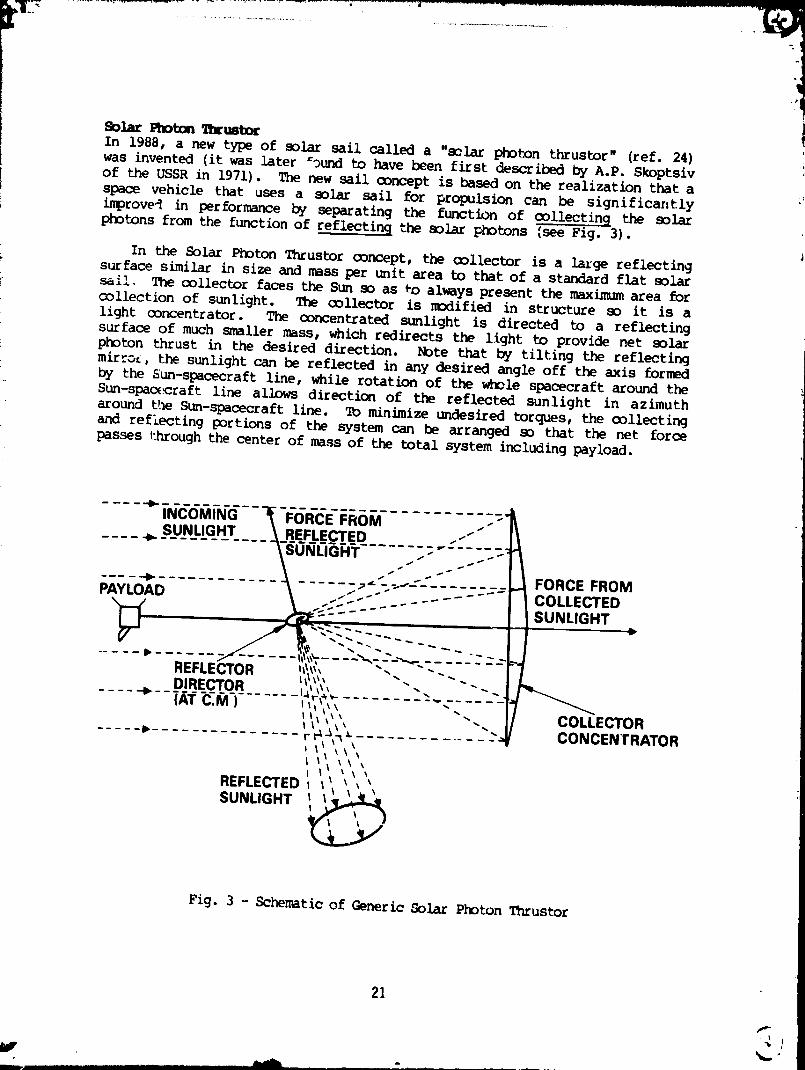
S_larFr_t_a_h_um_In 1988, a new type of solar sail called a "solar photon thrustor" (ref. 24)was invented (it was later =_und to have been first described by A.P. Skoptsiv
of the USSR in 1971). The new sail o0ncept is based on the realization that aIi
space vehicle that uses a solar sail for propulsion can be significantly
improve_ in performance by separating the function of (x)llecting the solarphotons from the function of reflecting the solar photons Isee Fig. 3).
In the Solar Photon Thrustor ooncept, the collector is a large reflecting
surface similar in size and mass per unit area to that of a standard flat solar
sail. The collector faces the Sun so as _o always present the maximum area forcollection of sunlight. The collector is modified in structure so it is a
light concentrator. The concentrated sunlight is directed to a reflecting
surface of much smaller mass, which redirects the light to provide net solarphoton thrust in the desired direction. Note that by tilting the reflecting
mir.oL,_-the sunlight can be reflected in any desired angle off the axis formedby the Sun-spacecraft line, while rotation of the whole spacecraft around the
Sun-space.raft line allows direction of the reflected sunlight in azimuth
around the Sun-spacecraft line. To minimize undesired torques, the collectingand reflecting portions of the system can be arranged so that the net force
passes through the center of mass of the total system including payload.
,.co.,NaFO.CEF.o. .-%-I_ SUNLIGHT ___REFLECTED .-"" I_
I IFORCE FROM
PAYLOAD _ ...5_..-"" .... - ..... | I COLLECTED
..... _ ...... _/w__ f_%_.... "_.--_--._....... c--F-f
REFLECTOR -'" "--- I L_ DIRECTOR "-. ,.. "" -J I "--._11_-.._,v-
fill, i\.... --.. I7 CO-O'LLECTOR%l ',\_
..... _'- r r__'__" "'4 / CONCENTRATOR
REFLECTED
SUNUGHT',
Fig. 3 - Schematic of Generic Solar Photon Tnrustor
Since the collector of the sunlight in the Solar Photon Thrustor is alwaysfacing the Sun no matter what the desired direction of thrust, the Solar Photon
Thrustor always operates in a maxini_ solar light power collection mode. This
is in contrast to a flat solar sail propulsion system where the collector and
reflector are the same sheet of reflecting material. In a flat solar sail
propulsion system, if the desired direction of thrust is not directly away fromthe Sun, the sail must he tilted at some angle 8 with respect to the Sun-sail
line. Since the sail is tilted toward the Sun, the effective collecting area
of the flat solar sail propulsion system is decreased by an amount proportionalto sin@. This means that the Solar Photon Thrustor always collects more solar
light power and therefore provides higher total sclar photon radiation pressure
force for the same area of collector. Since the mass of any optimized lightpressure propulsion system is dominated by the mass of the light cellecting
area, that means that a Solar Photon Thrustor system will have betterperformance in terms of maximum payload capability, maximum propulsive thrust,
and minimum mission time than flat solar sail propulsion systems. High solarpower concentration numbers are not needed for the Solar Photon Thrustor. A
concentration ratio of only I00:i means that the area (and t_herefore the mass)
of the reflecting optics will be 1% of the area (and mass) of the collectingoptics and therefore a negligible portion of the total spacecraft mass.
The electromagnetic radiation does not have to stay in its original form.For example, the collector could l_ollect sunlight and concent, _e it on a 9olaf
cell or thermal boiler electrical generation system. The el_ icity generatedcould be used to make microwave, laser, or other useful coherent radiation,
which would be be&reeddown to Earth. The waste heat from the process would beradiated away into space. Both the beamed coherent power and the radiated
waste heat would produce propulsive force of comparable magnitude to the
collected light. With proper system design, the beamed power and waste heat,along with the collected light, could provide all the propulsion needed.
Richard M_ss, M.D. of Plymouth, Massachusetts has found (ref. 25) that a
solar photon thrustor can he launched at shuttle altitudes. (Standard sails
can only operate above 1000 km altitude, where the light pressure force exceedsthe atmospheric drag.) If the solar photon thrustor is launched into a Sun-
synchronous orbit over the terminator, the large collector sail facing the Sunwill have minimum drag since it is flying edge-on to the residual atmosphere.
It only takes four days to go from Shuttle altitudes to a safe 1000 km drag-free altitude.
Solar Sa_Is fDr Msnned Missions to _u_s
John Garvey of McDonnell-Douglas has been reexamining the use of solar sails
for the manned exploration of Mars initiative. Prior studies by Carl Sauer ofJPL resulted in optimized trip times of 824.5 days (2.25 years) for an Earth to
Mars transfer. Garvey realized that most of that time was spent spiraling up
from LEO to escape, matching velocities with Mars with a sail tilt angle that
was alnDst edge-on to the Sun, and spiraling down from escape to LMO. By using
a mixture of chemical boost on departure, solar sail propulsion duringtransfer, and aerobraking upon arrival, Garvey has found non-optimized mission
profiles of 150 days one way, with even shorter return trip times for the emptysail. Tiese short mission times cut the crew consumable weight drastically andeliminate the need for artificial gravity.
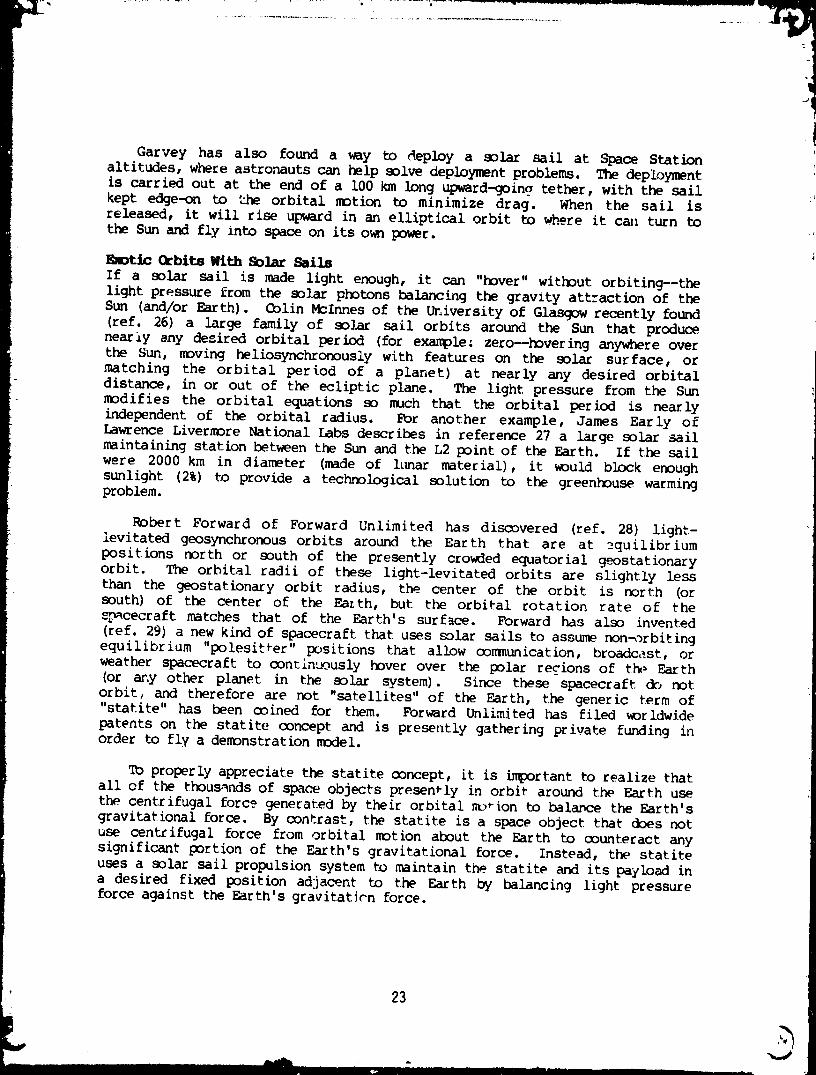
Garvey has also found a way to deploy a solar sail at Space Stationaltitudes, whece astronauts can help solve deployment problems. The deployment
is carried out at the end of a 100 km long upward-goin 9 tether, with the sail
kept edge-on to the orbital motion to minimize drag. When the sail isreleased, it will rise upward in an elliptical orbit to .whe._reit cml turn to
the Sun and fly into space on its own power.
Rm_tlc Orbits With Solar Sails
If a solar sail is made light enough, it can "hover" without orbiting--thelight pressure from the solar photons balancing the gravity attraction of the
Sun (and/or Earth). Colin McInnes of the University of Glasgow recently found
(ref. 26) a large family of solar sail orbits around the Sun that producenearly any desired orbital period (for example: zero--hovering anywhere over
the Sun, moving heliosynchronously with features on the solar surface, ormatching the orbital period of a planet) at nearly any desired orbital
distance, in or out of the ecliptic plane. The light pressure from the Sun
modifies the orbital equations so much that the orbital period is nearlyindependent of the orbital radius. For another example, James Early ofLawrence Livermore National Labs describes in reference 27 a large solar sail
maintaining station between the Sun and the L2 point of the Earth. If the sail
were 2000 km in diameter (made of l_ar material), it would block enoughsunlight (2%) to provide a technological solution to the greenhouse warming
problem.
Robert Forward of Forward Unlimited has discovered (ref. 28) light-
levitated geosynchronous orbits around the Earth that are at __quilibrium
positions north or south of the presently crowded equatorial geostationaryorbit. The orbital radii of these light-levitated orbits are slightly less
than the geostationary orbit radius, the center of the orbit is north (orsouth) of the center of the Earth, but the orbital rotation rate of the
spacecraft matches that of the Earth's surface. Forward has also invented
(ref. 29) a new kind of spacecraft that uses solar sails to assume non_rbiting
equilibrium "polesit_er" positions that allow o0mmunication, broadc_.st, orweather spacecraft to continuously hover over the polar recions of t_ Earth
(or any other planet in the solar system). Since these spacecraft do notorbit, and therefore are not "satellites" of the Earth, the generic term of"statite" has been coined for them. Forward Unlimited has filed worldwide
patents on the statite concept and is presently gathering private funding inorder to fly a demonstration model.
To properly appreciate the statite concept, it is i_portant to realize that
all of the thousands of space objects presently in orbit around the Earth usethe centrifugal force generated by their orbital mo_ion to balaDce the Earth's
gravitational force. By contrast, the statite is a space object that does notuse centrifugal force from orbital motion about the Earth to counteract any
significant portion of the Earth's gravitational force. Instead, the statite
uses a solar sail propulsion system t_)maintain the statite and its payload ina desired fixed position adjacent to the Earth by balancing light pressure
force against the Earth's gravitation force.
23
L• ,,, I -m
1991012826-026
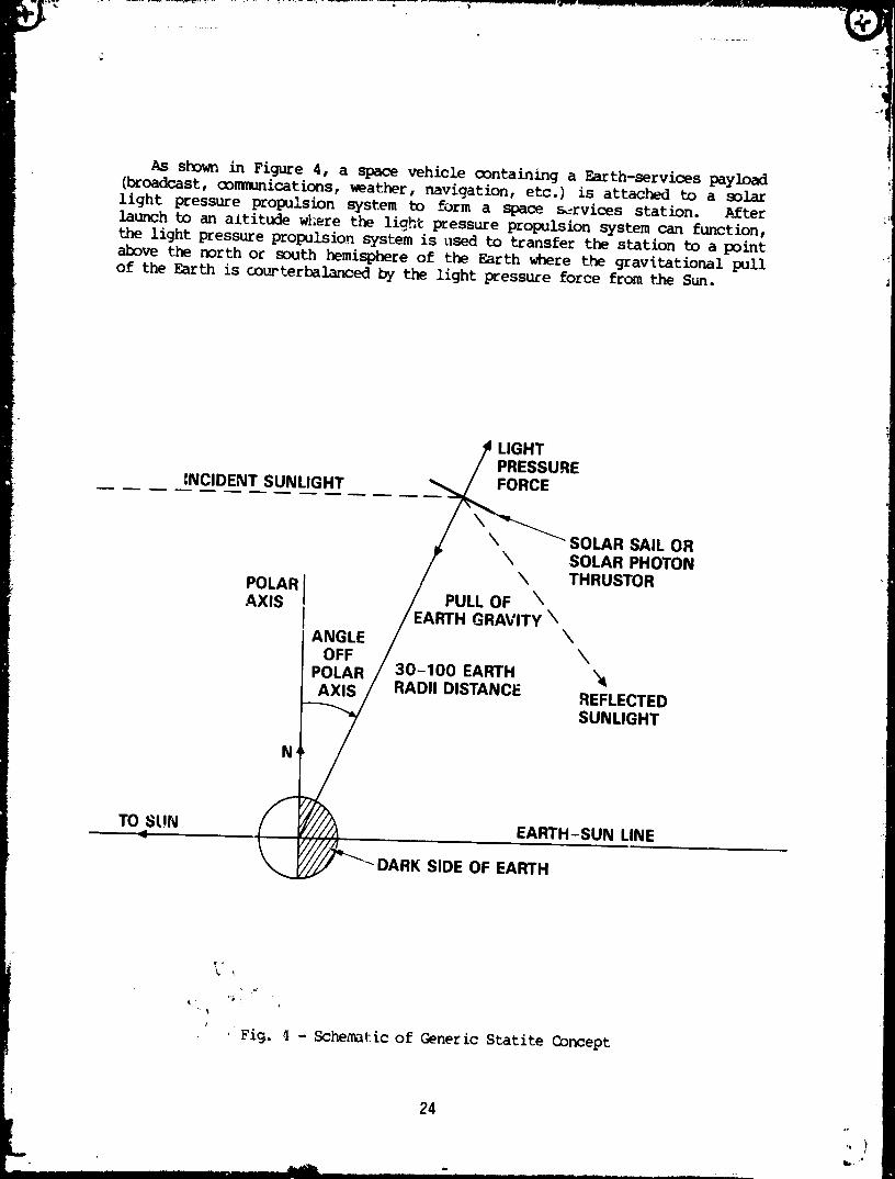
As shown in Figure 4, a space vehicle containing a Earth-services payload(broadcast,communications,weather, navigation, etc.) is attached to a solarlight pressure propulsion system to form a space s_rvices station. _fterlaunch to an altitude w_ere the light pressure propulsion system can function,the light pressure propulsion system is used to transfer the station to a pointabove the north or south hemisphere of the Earth where the gravitational pullof the Earth is oourterbalancedby the light pressure force from the Sun.
LIGHTPRESSURE
INCIDENT SUNLIGHT FORCE
k SOLAR SAIL OR\ SOLAR PHOTON
POLAR \ THRUSTORAXIS PULL OF \
EARTH GRAVITY \ANGLE \
OFF \POLAR 30-100 EARTHAXIS RADII DISTANCE REFLECTED
SUNLIGHT
N
TO SUN EARTH-SUN LINE
DARK SIDE OF EARTH
%
I
' Fi_. ; - Schematic of Generic Statite Concept
24
L ,I
...... ' .................... 2826-027........ '"" '"......... 199101
.v
In most versions of the system, the statite is offset from the polar axis.
The statite stays fixed at a point above the dark side of the Earth, while the
Earth spins beneath it. The statite does not have to be positioned directlyopposite from the Sun. It can be placed anywhere over a large area on the dark
side of the Earth. This is in contrast to the single linear arc of the
equatorial geostationary orbit. From the viewpoint of an observer on therotating Earth, this version of the statite rotates around the pole once every
24 hours (a solar day). Thu, ground stations for communication with thesestatites must have their anteru_s on a polar ,punt with a 24 hour clock drive.
{ Since the distance bet_t=en the ground station and the statite does not changesignificant': and the doppler shifts are very low, the electronics needed for
i these versions of the system are nearly as simple as those at the fixed
position ground stations. There is an alternate version of the statite system
where the statite is kept directly over the North or South Pole of the spinningEarth. To an observer on the Eazth, the statite stays fixed above the polewhile the stars rotate around it. In these versions, the ground stations can
used fixed mounted antennas and simple fixed gain, fixed frequency electronics.
A typical distance of a statite from the center of the Earth is 30 to 100Earth radii. The better the performance of the sail, the closer the balance
point. (For reference, geostationary orbit is at 6.6 Earth radii and the Moonis at 63 Earth radii.) The round-trip delay time for 100 Earth radii is 4
seoonds, making the statite more suitable for direct broadcast, fax, data, and
weather services than two-way telephone conversations. The advantages of the
statite concept are: it provides continuous service to a region using a singlespacecraft without requiring a slot on the already crowded equatorialgeostationary orbit, and it provides continuous coverage to regions of the
Earth that are too close to the poles to use equatorial geostationary orbit
satellites. T_e disadvantages of the statite concept are: constant control isrequired to maintain station, the round-trip link time is in seconds, and in
most versions the ground station antenna must rotate once a day.
_C SAILS
Magnetic sails or "magsails" are a derivative form of solar sails that use
a completely different type of physical interaction with the Sun than solar
light pressure sails (ref. 30). Invented by Dana Andrews of Boeing Aerospace
and Robert Zubrin of Martin-Marietta Denver, a magsail is a simple loop ofhigh-temperature superconducting wire carrying a persistent current. The
charged particles in the solar wind are deflected by the magnetic field,producing thrust. Although the thrust density in the solar ion wind flux is
five thousand times less than the thrust density in the solar photon flux, the
mass of a solar sail goes directly as the area, while the mass of the magsailgoes as the perimeter of the area enclosed. In addition, the effective cross-
sectional area of the magnetic fields around the magsail is about a hundredth,es the physical area of the loop. As a result, preliminary calculations
show the thrust-to-weight of a magsail can be an order of magnitude better than
a solar sail. Recent analyses indicate that a properly sun-shielded cable canbe passively maintained at a temperature of 65 K in space, well below the
superconducting transition point for many of the new high-temperaturesuperconductor s.
25
V
-" " "" ............... '...... 0-' 2-826-028..... """ .......... 1991 1
"IJ
Tether propulsion a technology that will fly soon. NASA is funding Martin
Marietta to build the tether (2.5 mm diameter and I00 km long) and deployment
mechanism, while Italy is building the spacecraft that will fly at the end o£
the tether. The first experiment, scheduled for 1991, will deploy thespacecraft froward from the Shuttle on a conducting tether cable to demonstrate
power generation from the .Totion of the cx)nducting cable through the Earth'smagnetic field. By pumping current through the cable, thrust would be
generated by the "push" of the cable against the Earth's magnetic field. The
seoond flight will deploy an atmosl_heric research spacecraft downward, where itwill fly through the upper atmosphere, t_o low for spacecraft and too high for
aircraft. The tether connection to the Shuttle spacecraft provides the
propulsion needed to overcome the Orag. Ivan Bekey, formerly at NASA
Headquarters and now on the National Space Oouncil, has been championing theuse of tethers for many space applications (ref. 31 and 32), including throwing
payloads from LEO to GBO, electromagnetic pro_Jlsion using a conductive tether,
and momentum transfer through the Space Station. In the latter application, anOrbital Transfer Vehicle is launched from an upward going tether at the s_me
time as the Space Shuttla deorbits from a down-going tether, all without usingany fuel. The Spaee Station is unaffectedNit aerely transfers energy andmomentum between the two vehicles. Paul Penzo of JPL has shown (ref. 33) it is
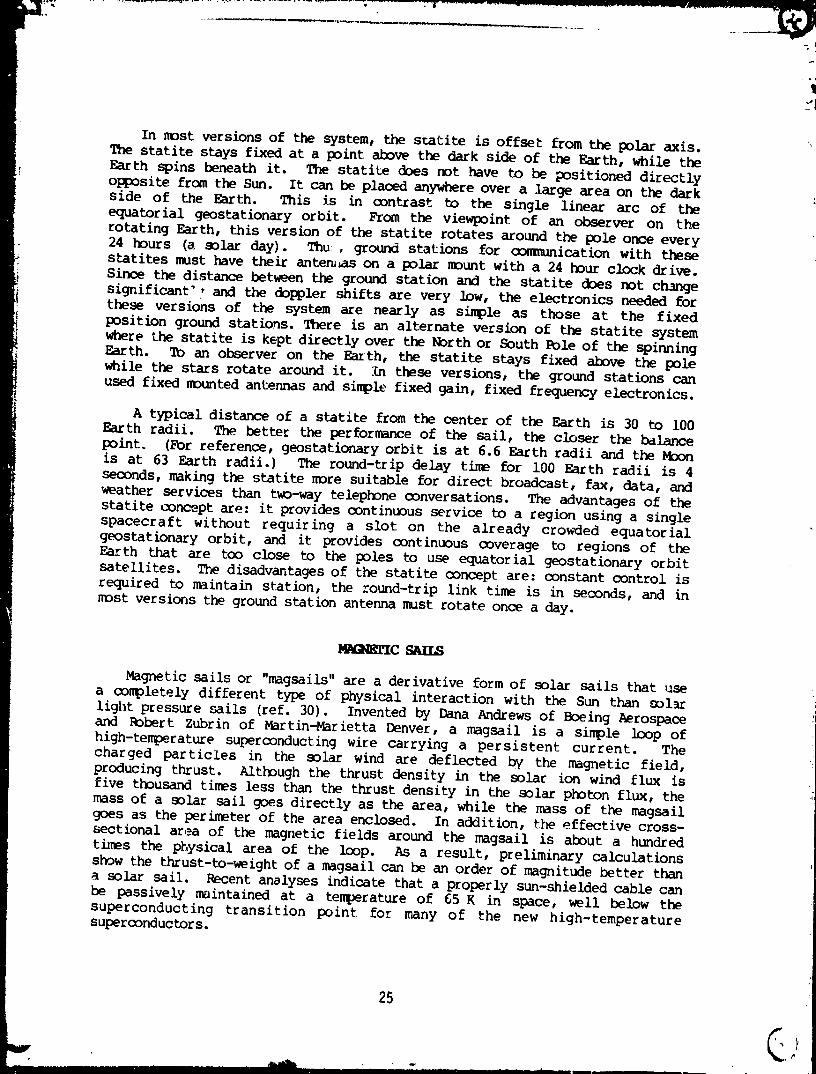
possible to use tethers to move payloads from planetary body to plmnetary body(see Fig. 5), such as low Martian orbit to low Earth orbit.
RELEASE
/ I _" ___ km
/ / _ "_L MO ESCAPE
/ I
/ II I
RENDEZVOUSI _ OEIMOS /
!_ LAUNCH
s
\ I\ / RELEASE\
"_ RENDEZVOUS
! 1160 km //
/
(_ PHOBOS //
I L - 940 km _,,fP _ Ptcllo, liD.
RELEASE
Fig. 5 - Schematic of Generic Mars Tether Transport System
26
1991012826-029
.IT .............-T°
i
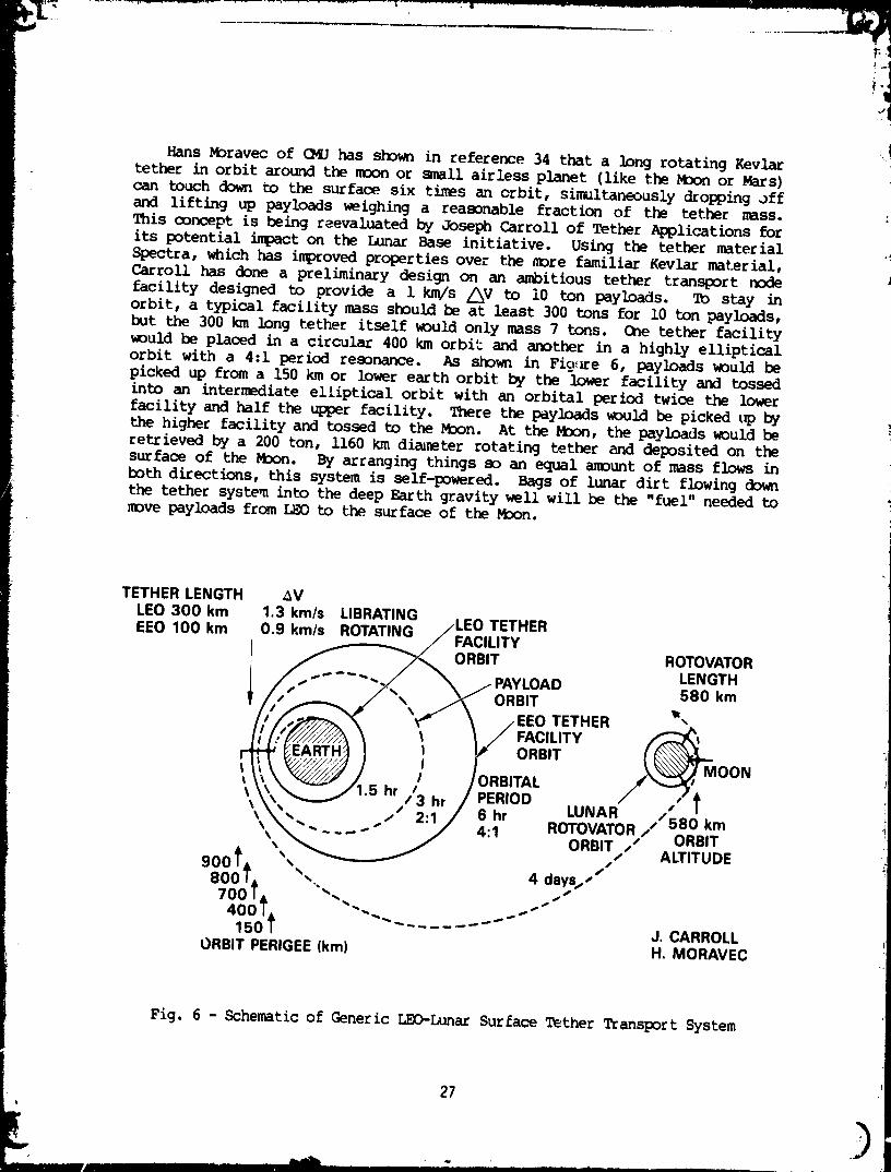
Hans Moravec of OfJ has shown in reference 34 that a long rotating Kevlartether in orbit around the moon or small airless planet (like the Moon or Mars)can touch down to the surface six times an orbit, simultaneouslydropping offand lifting up payloads _ighing a reasonable fraction of the tether mass.This concept is being reevaluated by Joseph Carroll of Tether Applications forits potential impact on the Lunar Base initiative. Using the tether materialSpectra, which has improved properties over the more familiar Kevlar material,Carroll has done a preliminary design on an ambitious tether transport nodefacility designed to provide a 1 km/s /_V to i0 ton payloads. To stay inorbit, a typical facility mass should be at least 300 tons for i0 ton payloads,but the 300 km long tether itself would only mass 7 tons. One tether facilitywould be placed in a circular 400 km orbit and another in a highly ellipticalorbit with a 4:1 period resonance. As shown in Fig Ee 6, payloads would bepicked up from a 150 km or lower earth orbit by the lower facility and tossedinto an intermediate elliptical orbit with an orbital period twice the lowerfacility and half the upper facility. There the payloads would be picked _ bythe higher facility and tossed to the M3on. At the Mnon, the payloads would beretrieved by a 200 ton, 1160 km diareter rotating tether and deposited on thesurface of the M_on. By arranging things so an equal amount of mass flows inboth directions, this system is self-powered. Bags of lunar dirt flowing downthe tether system into the deep Earth gravity well will be the "fuel" needed tomove payloads from LEO to the surface of the Moon.
TETHER LENGTH _VLEO 300 km 1.3 km/s LIBRATINGEEO 100 km 0.9 km/s ROTATING /LEO TETHER
,/FACILITY
//_____ _'_ ORBIT ROTOVATOR/ _--''-// X /PAYLOAD LENGTH
,_ _\_\_ ORBIT I,,580 km
/ EEO TETHER/ FACILITY
, / /ORBITAL /_''-
/;T:°°'\_-. ./" 2'1/ 4'1 ROTOVATOR / _,.,%,,km_\"_,_ ' ORBIT ,," un=H
/ ALTITUDE900 IL, ',
800/, "" 4 days,/"'_700/& '",, ""
400/& . _150 / "'""" --- J. CARROLL
ORBIT PERIGEE(km) H. MORAVEC
Fig. 6 - Schematic of Generic LEO-Lunar Surface Tether Transport System
27
L ),, , .... Ill IIIII I I I .....
........ 19910128262030
Tether"Bootstrap"Pzop_IskmGeoffrey Landis at NASA/Lewis has shown in reference 35, how a spacecraftstarting in a low circular orbit about Earth can use a power supply and a long
tether "pushing" against the Earth's gravity gradient field to "bootstrap"
itself (and the tether) up the gravity well nearly to escape in less than a
month without using propellant. The basic concept is based on the fact that iftwo halves of a spacecraft (or a spacecraft and its expended booster) are
extenuatedon a long tether, the center-of-mass of the extended system shiftsslightly downward from the original center-of-mass and the orbital period
decreases. This shift in the center-of-mass occurs because the Earth's gravityforce causes an acceleration on the masses that varies as i/r2, while the
oounteracting centrifugal force due to orbital motion causes an acceleration
that varies as r. For very long tethers, the t_p forces no longer exactlycancel at the two ends and there is a residual, second order, force which .llSt
be balanceu by a shift in the center of mass. When the tether is pulled in
again, the center-of-mass of the combined system raises upward.
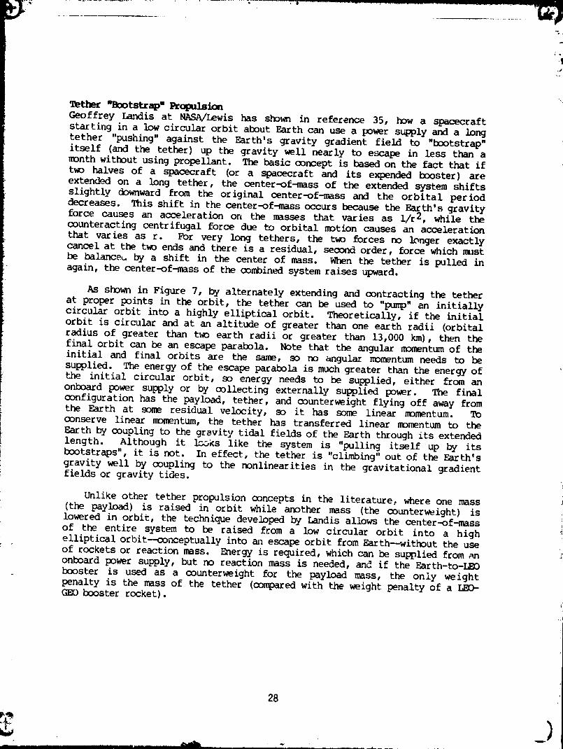
As shown in Figure 7, by alternately extending and contracting the tether
at proper points in the orbit, the tether can be used to "pump" an initiallycircular orbit into a highly elliptical orbit. Theoretically, if the initial
orbit is circular and at an altitude of greater than one earth radii (orbital
radius of greater than two earth radii or greater than 13,000 kin), then the
final orbit can be an escape parabola. Note that the angular momentum of theinitial and final orbits are the same, so no angular momentum needs to be
supplied. The energy of the escape parabola is much greater than the energy of
the initial circular orbit, so energy needs to be supplied, either from anonboard power supply or by collecting externally supplied power. The final
configuration has the payload, tether, and counterweight flying off away fromthe Earth at some residual velocity, so it has some linear momentum. Toconserve linear momentum, the tether has transferred linear momentum to the
Earth by coupling to the grevity tidal fields of the Earth through its extended
length. Although it _lc_ks like the system is "pulling itself up by itsbootstraps", it is not. In effect, the tether is "climbing" out of the Earth's
gravity well by coupling to the nonlinearities in the gravitational gradientfields or gravity tides.
Unlike other tether propulsion concepts in the literature, where one mass
(the payload) is raised in orbit while another mass (the counterweight) islowered in orbit, the technique developed by Landis allows the center-of-mass
of the entire system to be raised from a low circular orbit into a high
elliptical orbit--conceptually into an escape orbit from Earth--without the useof rockets or reaction mass. Energy is required, which can be supplied from anonboard power supply, but no reaction mass is needed, and if the Earth-to-LEO
booster is used as a counterweight for the payload mass, the only weight
penalty is the mass of the tether (compared with the weight penalty of a LEO-GEO booster rocket).
28
............ 1991012826-031
apogee: extend tether
perigee: retract tether
Fig. 7 - Schematic of Generic Tether "Bootstrap" Propulsion Concept
29
1991012826-032
1q
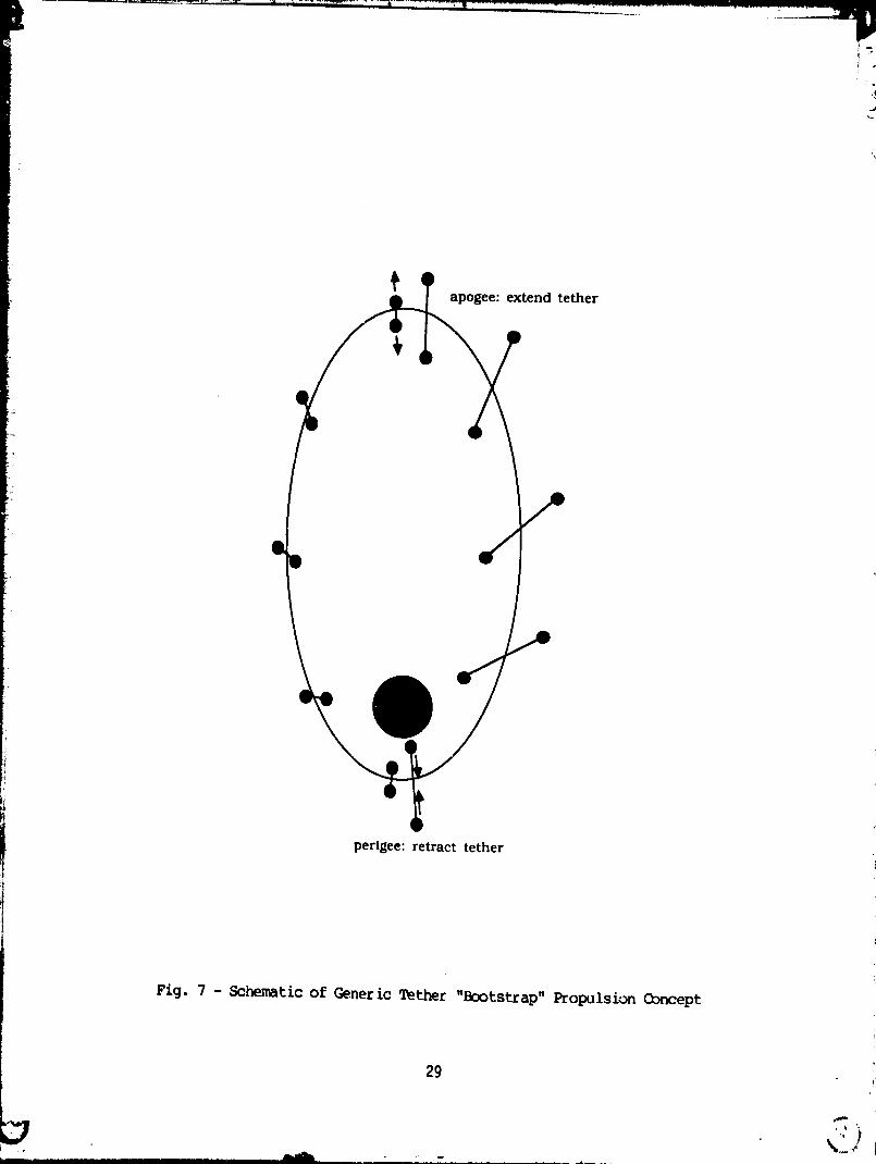
iiA cable catapult is a new type of propulsion system proposed by Forward _hat :
uses a long tether as a launch rail (ref. 36). As shown in Figure 8, the
tether cable is pointed in the desired direction of travel. A payload is
attached to a linear motor capable of traveling along the cable. The linear' mptor accelerates along the cable until the payload reaches the desired launch
velocity, at which point the payload is released. The linear motor thendecelerates to a halt to await the arrival of an inooming payload.
PAYLOADI. LEAVES
!i \ S%)_J/ DECELERATESTO STOP'_ \ /__ WAITS FORINCOMING
__ _"_ PAYLOADSEPARATES_.r/ FROM LINEARMOTOR 7
LINEARMOTOR __'-_._ I_ ACCELERATESPAYLOAD
ALONGCABLE
Fig. 8 - Schematic of Generic Cable Catapult Goncept
In the past, tethezs have been considered for transporting payloads to andfrom the Moon, Mars, and other bodies in the solar _rstem. These tether
i propulsion systems usually involved swinging or rotating tethers. M_ravec has
i shown that the maximum tip speed V of a rotating tether (and therefore themaximum speed at which a rotating tether can launch a payload) is a function of
_' the "characteristic velocity" of the cable given by the square root of the
ratio o_ the desiqn tensile strength T to the density d of the material in thetether or v= (T/d)][/2and the ratio of the mass M of the tether to the mass m of
the payload. The exact expression is:
2 2
M 1/2 V V /2v
--- = (_) --- e erf(V/2v)m v
30 .
1991012826-033
where erf is the error function (typically of order unity or less). This can
be compared to the ratio of the rocket mass to the payload mass of a rocketwhere v is the "exhaust velocity" of the fuel.
M V/v---=e -im
Which is exponential in V/v, while the rotating cable mass ratio is exponentialin the square of V/v. In contrast, Forward has sho_ in reference 36, that the
ratio of the tether mass to the payload mass used in the cable catapult modevaries as:
M 2 2
--- =V/2v .m
Because of the squared exponential growth of the. mass of the tether in a
rotating tether system, the maximum launch velocity attainable for practical
launcher to payload mass ratios is tP_ree times the characteristic velocity ofthe cable mater ial or 3 km/s for a 1 km/s Kevlar cable. A cable catapult using
the same amount of cable material could give the payload a launch velocity of
30 times the cable characteristic velocity or 30 km/s. Improved cable
materials having higher characteristic velocities will allow interplanetarytravel at 30-100 km/s. This could shorten trip times to Mars from years tomonths.
FAR FJTOREI_SmJLSIGN
Even more exotic propulsion concepts abound in the literature. Manyadvanced nuclear propulsion concepts have been proposed that depend upon som_
exotic physical process being found practical. For one example, George
Chapline of Lawrence Livermore National Lab has proposed a fission fragment
rocket using thousands of kilometers of americium coated fibers suspended ondozens of rotating 100-meter-sized wheels as a combination fuel source and heat
radiator. Others have examined the propulsion applications of variouspotential techniques for catalyzed cold fusion, using palladium, muons,
fractional charges, magnetic monopoles, and strange matter. None of these
fusion techniques look promising for propulsion, primarily since in most cases
the energy output is in the form of high energy neutrons, which are difficultto turn into thrust except through an indirect thermalization process.
We do not lack new ideas to explore: some examples are studies on laser and
microwave pushed sails to the planets and stars (ref. 37 and 38), andextracting laser power from the mesospheres of Mars, Venus, and maybe Earth
(ref. 4). Even further out are recent papers on negative matter propulsion
(ref. 29), space warps (ref. 40), and serious-but-skeptical studies ofBiefield-Brown field propulsion and electrogravity induction field theories(ref. 22).
31
b ,'I....... _i%IiiL , =, i.,. .i., , ...... II _ .....
'"" ....""" ....... 1991012826-034
In this review I have discussed a number of e_otic power and propulsion
techniques, ranging from eminently feasible to the wildly impossible. But it
is important for you, the reader, to realize that my main message is that we .:,don't need to wait for truly e_otic technologies like metallic hydrogen,antimatter, or space warps to improve the nation's space propulsioncapabilities by orders of magnitude increase in performance and orders of
magnitude decrease in cost. Chemical rocket propulsion is fine when the /_V issmall, but for the more a._Ditious missions, this nation needs to putsubstantial development funds into making real those advanced _pace propulsiontechnologies that have already shown their potential value in decade afterdecade of paper studies.
Solar and nuclear electric propulsion should oome first, not small systems
for secondary tasks like North-South station keeping or Space Station dragmakeup, but large megawatt and multimegawatt primary propulsion systems for O1_
tugs, Earth-Lunar shuttles, and manned missions to Mars. Then solar sails,first for communication, broadcast, and especially weather .satellites that arenot limited to the equatorial geostationary orbital arc, second for scientific
monitoring stations hovering over the Sun, planets, and moons of the solar
system, and third for hauling cargo to and from Earth, the planets, and theasteroid belt--without the expenditure of fuel.
Next should come rotovators made of long rotating Kevlar tethers that willallow txansport of massive quantities of material to and from low orbit to the
surface of planetary bodies such as the M_on, Mars, Mercury, and most of the
,Dons in the solar system--again without the use of fuel. RDtating tethersaround the Earth could also move massive amounts of material from LED to GEO or
escape--using no fuel in the process as long as the amount of material being
brought down the gravity well of Earth exceeds the amount being hauled up.
To get off the Earth and into LEO, we must either bite the political bulletand push high-thrust hot hydrogen exhaust nuclear thermal rockets with their
radiation hazard, or stick with chemical rockets and their greenhouse hazard.High thrust laser propulsion, either pulsed or (_N, is an alternate choice with
its own set of operational and environmental problems that need engineeringdemonstration, not another mile-high stack of paper _tudies.
Mission planners must use what they know works in order to plan a mission.
If future missions, such as a return to the Moon, or the manned exploration ofMars, are to be made economically feasible, NASA needs to stop the interminablepaper studies and move into the development and demonstration of advanced forms
of space propulsion such as nuclear, electric, lightsail, tether, and laser
propulsion. That way, those mission planners will have some viable
alternatives to work with. Otherwise, this nation is going nowhere in space.
32
1991012826-035
1
This _esearch was supported in part by NASA/Lewis Research Center and in
part by the Air Force Astronautics Laboratory through Contract F04611-87-C-0029with Forward Unlimited.
i. S.K. Borowski, E.A. Gabris, and J. Martinell, "Nuclear Thermal
Rockets", Aerospace America, 27, 16-18 (June 1989).
2. Robert W. Bussard, "Fusion as Electric Propulsion", AIAA Paper 88-3167,
AIAA/SAE/ASME/ASEE 24th Joint Propulsion Conference, Boston,
Massachusetts (11-13 July 1988.
3. V.E. Haloulakos and R.F. Bourque, "Fusion Propulsion Systems", AIAA
Paper 89-2629, AIAA/SAE/ASME/ASEE 25th Joint Propulsion Conference,Monterey, California (11-13 July 1989).
4. R.L. Forward, Alternate Propulsion Energy Sources, AD:B088771, AFRPL-TR-83-067, AFRPL, Edwards AFB, CA 93523-5000; Final Report on ContractF04611-83-C-0013 with Forward Unlimited, P.O. Box 2783, Malibu, CA
90265 (December 1983).
5. R.L. Forward, Antiproton Annihilatio n Propulsion, AD:A160734, AFRPL-TR-85-034, AFRPL, Edwards AFB, CA 93523-5000; Final Report on ForwardUnlimited subcontract RI-32901 to Contract F04611-83-C-0046 with
University of Dayton Research Institute, Dayton, Ohio 45469 (September1985).
6. R.L. Forward, Advanced Space Propulsion Study: Antiproton and Beamed
Power Propulsion, AD:A189218, AFAL-TR-87-070, AFAL, Edwards AFB, CA93523-5000; Final Report on Contract F04611-86-C-0039 with Forward
Unlimited, P.O. Box 2783, Malibu, CA 90265 (October 1987).
7. R.L. Forward, "Antiproton Annihilation _ropulsion", J. Pro_x_]sion, I,370-374 (September-October 1985).
8. Robert L. Forward, Brice N. Cassenti, and David Miller, "Cost iComparison of Chemical and Antihydrogen Propulsion Systems for High /_VMissions", AIAA Paper 85-1455, 21st Joint Propulsion Conference,Monterey, California (8-10 July 1985). :]
9. Robert L. Forward and Joel [_vis, Mirror Matter: Pioneering Antimatter
Physics, John Wiley & Sons, Wiley Science Editions, New York (1988).
10. Mauro Pecchioli and Giovanni Vulpetti, "A M_/iti-Megawatt Antimatter
Engine Design Concept for Earth-Space and Interplanetary UnmannedFlights", IAF Paper 88-264, 39th Congress of the International
Astronautical Federation, Bangalore, India (8-15 October 1988).
33
Q
1991012826-036
-2
ii. B.W. Augenstein, et al., Editors, Antiproton Science and Technology,Proc. Rand Workshop on Antiproton Science and Techno]ogy, RANDCorporation, Santa Monica, California (6-9 October 198;); WorldScientiflc, Singapore (1988).
12. G. Gabrielse, et al., "Cooling and Slowing of Trapped Antiprotons below100 meV", Physical Review Letters, 63, 1360-1363 (25 September 1989).
13. W.J. Lauderdale and W.A. Sowe11, Editors, Proceedings of the HighEnergy Densit_ Matter (HE_M) Conference, RDsslyn, Virginia, 12-13 May1987, AFAL CP-87-002, Air Force Astronautics Laboratory, _wards AFB,CA 93523-5000 (September1987).
14. Larry P. Davis and Francis J. Wodarczyk, Editors, Proceedlngs of theAir Force High Ener_ Densit_ Materials ContractorsConference, NewportBeach, California, 28 February - 2 March 1988, Air Force Offioe ofscientific Research, Bolling AFB, DC 20332-6448 (27 April 1988).
15. T.G. Wiley and R.A. van Opijnen, Editors, Proceedin s of the Hi hlouisiana, 12-15EnergY Densit_ Matter (_U_M! Conference, New Orleans,
March 1989, AL-CP-89-002, Ast_ Laboratory (AFSC), Edwards AFB,CA 93523-5000 (July 1989).
16. H.K. Mao and R.J. Hemley, "Optical Studies of Hydrogen Above 200Gigapascals: Evidence for Metallizationby Band Overlap", science, 244,1462-1465 (23 June 1989).
17. Richard A. Gerwin, Characterizationof Plasma Flow Throuc_h_MagneticNozzles, Los Alamos National Laboratory, Final Report on Contract RPL69018 with Air Force Astronautics Laboratory, Edwards AFB, CA 93523-5000 (i May 1986 to 30 April 1987).
18. A. Kantrowitz, "Propulsion to Orbit by Ground-Based Lasers",Aeronautics & Astronautics,I0, 74-76 (May 1972).
19. Jordin Kare, "Pulsed Laser Propulsion for Low Cost, High Volume Launchto Orbit", Lawrence LivermoreNational Laboratory preprint UCRL-101139,IAF Conference on Space Power, Cleveland, Ohio (5 June 1989)
20. D. Keefer, A. Sedghinasab,N. Wright, and Q. Zhang, "Laser PropulsionUsing Free Electron Lasers", 21st Int. Electric Propulsion Conferer_e, .iorlando, Florida (18-20July 1990).
21. Leik N. Myrabo, Transatm_spheric Laser Propulsion, Final Re_ort on _Contract 2073803 with Lawrence Liverm_re National Laboratory and theSDIO Laser Propulsion Program, 30 June 1989.
22. Franklin B. Mead, Jr. "E_otic Concepts for Future Propulsion and SpaceTravel", Proc. 1989 JANAAF Propulsion Meeting, Cleveland, Ohio (23-25May 1989)
34
1991012826-037

23. Louis Friedman, Starsailin@" Solar Sails and Interstellar Travel, JohnWiley & Sons, New York (1988).
24. Robert L. Forward, "Solar Photon Thrustor", AIAA Paper 89-2545,
AIAA/ASME/SAE/ASEE 25th Joint Propulsion Conference, Monterey,
California (10-12 July 1989). [Accepted for J. S_acecraft.]
25. Richard A. Moss, "Minimum Operation_1 Altitudes of Two Solar SailDesigns" (1990). [Unpublished preprint submitted to J. Astronautical
Sciences, obtain from author, ii0 Long Pond Road, Plymouth, MA 02360.]
26. C.R. McInnes and J.F.L. Simmons, "Halo Orbits for Solar Sails--Dynamicsand Applications", ESA Journal, 19, 229-234 (1989).
27. James T. Early, "Space-Based Solar Shield to Offset Greenhouse Effect",
J. British Interplanetary Society, 42, 567-569 (1989).
28. Robert L. Forward, "Light-Levltated Geostationary Cylindrical Orbits:Correction and Expansion", (Preprint dated 1988). [Accepted forpublication in J. Astronautical Sciences.]
29. Rpbert L. Porward, "The Statite: A Non-Orbiting Spacecraft", AIAA Paper89-2546, AIAA/ASME/SAE/ASEE 25th Joint Propulsion Conference, Monterey,
California (10-12 July ].989). [Accepted for J. Space_craft.]
30. R.M. Zubrin and D.G. Andrews, "Magnetic Sails and InterplanetaryTravel", AIAA Paper 89-2441, AIAA/ASME/SAE/ASEE 25th Joint Propulsion
Conference, Monterey, California (10-12 July 1989). [Accepted for
publication in J. Spacecraft.]
31. Ivan Bekey, "Tethers Open New Space Options", Aeronautics &Astronautics, 21, 32-40 (April 1983).
32. Ivan Bekey and Paul A. Penzo, "Tether Propulsion", Aerospace America,24, 40-43 (July 1986).
33. P. Penzo and H.L. Mayer, "Tethers and Asteroids for Artificial Gravity
Assist in the Solar System", J. Spacecraft, 23, 79-82 (January-February1986).
34. H. Moravec, "A Non-Synchronous CEbital Skyhook", J. AstronauticalSciences, 25, 307-322 (October-December 1977).
35. Geoffrey A. Landis and Frank J. Hrach, "satellite Relocation by TetherDeployment", NASA Technical Memorandum 101992, NASA Lewis Research
Center, Cleveland, Ohio (April 1989).
36. Robert L. Forward, "The Cable Catapult", Preprint FUn-90-011, ForwardUnlimited, P.O. Box 2783, MaliDl, CA 90265 (1990). [Submitted to
J. Spacecraft. ]
35
I - " • .............
1991012826-038
37. RDbert L. Forward, "RDundtrip Interstellar Travel Using Laser-PushedLightsails", J. Spacecraft, 21, 187-195 (March-April 1984).
38. Robert L. Forward, "Starwisp", J. Spacecraft, 22, 345-350 (May-June1985).
39. Robert L. Forward, "Negative Matter Propulsion", J. Propulsion, 6,28-37 (1990).
40. Robert L. Forward, "Space Warps: A Review of One Form of Propulsionless
Transport", J. British Interplanetary Society, 42, 533-542 (1989).
36
L
ram,nmmnn ............ I I
1991012826-039


![[014] ass 014 [1881]](https://img.pdfslide.net/doc/110x75/5695d38d1a28ab9b029e5607/014-ass-014-1881.jpg)
