Embed Size (px)
Citation preview

2018-07-0919915828
Marvin Window and Door MullingField Applied Instructions
ABSTRACT: The following instructions are intended to instruct a qualified window and door expert on how to as-semble window and doors in various mullion conditions including standard mulls, 3/8" mull reinforcement, spacemulls, and LVL mulls. These instructions assume a high level of user competency and that they are confident usingpower and hand tools, modifying the frame of the window or door, and performing all the tasks within. Read theseinstructions thoroughly before beginning.
These instructions are used for the following products:
• Clad Casement family
• Clad Ultimate Double Hung Next Generation 2.0 family
• Clad Ultimate Glider family
• Clad Polygon and Round Top
• All Clad doors except Lift and Slide, Bifold, and Multi-Panel Sliding doors.
Table of ContentsMULL TYPES AND CONFIGURATIONS .................... 2FIELD PREPARATION................................................ 5Corner Notches........................................................... 53/8" Aluminum Mull Reinforcement (MRF) Prep ......... 7Assembly .................................................................... 9Frame Prep ............................................................... 14Sealant Application-3/8" MRF ................................... 14Sealant Application-Space Mulls............................... 15Mull Cover Application .............................................. 16
Multi High/Multi Wide Assemblies ............................. 16Install Field Applied Casings ..................................... 17

2018-07-09 2 Marvin Window and Door Mulling19915828 Field Applied Instructions
MULL TYPES AND CONFIGURATIONS
Ribbon/Stacked (Standard) Mulls
Figure 1 Ribbon mull (standard)
A ribbon or stacked (standard) mull is one in which theframes are joined tightly together with no reinforcementor space between.
Mull Reinforcement (MRF)
Figure 2 Mull Reinforcement (MRF)
Mull Reinforcement or MRF are vertical or horizontalmulls that have aluminum reinforcement members at-tached to the them and are clipped and fastened togeth-er making the mull 3/8" wide.

2018-07-09 3 Marvin Window and Door Mulling19915828 Field Applied Instructions
Space Mulls
Figure 3 Space Mull (factory applied shown)
Space Mulls are vertical or horizontal mulls with woodblocking between them to a specified width. They aresealed at each end and covered at the exterior with ametal space mull cover. Space mulls come in 3/8", 1",2", 3", 4" and 6" size widths.
Laminated Veneer Lumber (LVL) Mull
Figure 4 LVL Mull (sealant application not shown in inset)
LVL Mulls are used for structural applications and comefrom Marvin in 1" and 2" widths (other widths may beavailable from other sources). Similar to space mullsand MRFs they are sealed at the ends and covered tothe exterior with a metal mull cover.

2018-07-09 4 Marvin Window and Door Mulling19915828 Field Applied Instructions
Stud Pocket Mull
Figure 5 Stud Pocket Mull
Stud Pocket Mulls are similar to space mulls except thewood blocking is removed just prior to the window beinginstalled.
Configurations
Figure 6 Mull diagram example from quote system
All mull configurations are diagrammed with the samerules as viewed from the exterior. The alphabetical labeldenotes the horizontal row starting with the top. The nu-merical label denotes the vertical column starting fromthe left. For example, A1 is always the top left unit asviewed from the exterior.
When laying out your assembly, refer to the quote dia-gram and the corresponding label on the unit.
Figure 7

2018-07-09 5 Marvin Window and Door Mulling19915828 Field Applied Instructions
FIELD PREPARATION
Corner Notches
If you have ordered your assembly factory prepped formulling, verify that the correct corners have beennotched. If not refer to the steps below starting with step3.
1. Any corner that intersects a mull must have a notch cut out of the accessory kerf cladding such as that shown in Figure 8. Notching allows room to apply the mull cap and frame trim later.
Figure 8
Figure 9 Notch Locations
1 close up of notched corner
1 Standard Mull 2 wide (notch at the headjamb)
2 2 wide x 2 high direct mull, MRF, and spacemull (notch all corners of the intersection
3 2 wide x 2 high with transom on top (notch tops of both lower units and ends)

2018-07-09 6 Marvin Window and Door Mulling19915828 Field Applied Instructions
3. To make a notch, remove the exterior wall of the accessory kerf with a sharp chisel. Only remove material from the accessory kerf that is perpendicular to a mull. (multiple high/multiple wide configurations will have both walls of the corner(s) notched out). See Figure 10 and Figure 11.
Figure 10
Figure 11 Notching detail for intersecting mulls

2018-07-09 7 Marvin Window and Door Mulling19915828 Field Applied Instructions
3/8" Aluminum Mull Reinforcement (MRF) Prep
This section focuses on preparing an assembly for mullreinforcement if it has NOT been factory applied. Referto your mull diagram to identify the location of your mullreinforcement(s).
4. MRF KERF: If the units in your assembly have not been prepped for MRF and have no accessory kerf in the wood sides of the jamb, you will need to cut a 1/8" wide by 1/4" deep kerf. Use a circular saw and guide to cut the kerf 2 1/4" (32) from the edge of the frame. See Figure 12
NOTE: Some full frame units will not have a factory fab-ricated kerf. All narrow frame product does have a kerf.Images throughout this section show a full frame unitbut narrow frame applies as well.
Figure 12
5. Apply MRF Components to the frames. Apply a 3/8" bead of Dow Corning® 791 (or equivalent) to the jambs in a wiggle pattern. See Figure 13.
Figure 13
1 1/8" (3)
2 1/4" (6)
3 2 1/4" (32)
1 Dow Corning 791 sealant or equivalent

2018-07-09 8 Marvin Window and Door Mulling19915828 Field Applied Instructions
6. The MRF components come in two parts. The beige piece always has the hooked end to the interior. The black piece always has the “hooked” end to the exterior. Insert the alignment leg on the MRF component into the MRF kerf in the frame. Flush the MRF component with the end of the mull and fasten to the frame with #8x5/8" screws in every hole of the MRF. See Figure 14.
Figure 14
1 Beige MRF (hooked end to interior of units)
2 Black MRF (hooked end to exterior of units)
3 Alignment leg fits into kerf on frame
4 #8x5/8" screws
2018-07-09 9 Marvin Window and Door Mulling19915828 Field Applied Instructions
Assembly
Direct Mulls
Using a smartphone or similar device, scan the QRcode below or click here to play a video of this proce-dure.
7. When possible, remove operating sash from frames and set aside.
8. Refer to your mull assembly diagram and place the individual units on a flat sturdy surface in the correct orientation, exterior side up. If already applied, remove drip cap(s) and jamb nailing fin where units will be mulled.
9. Notch your corners at the appropriate locations (if not already done). Refer to the section, Corner Notches on page 5 for details if you need to do this.
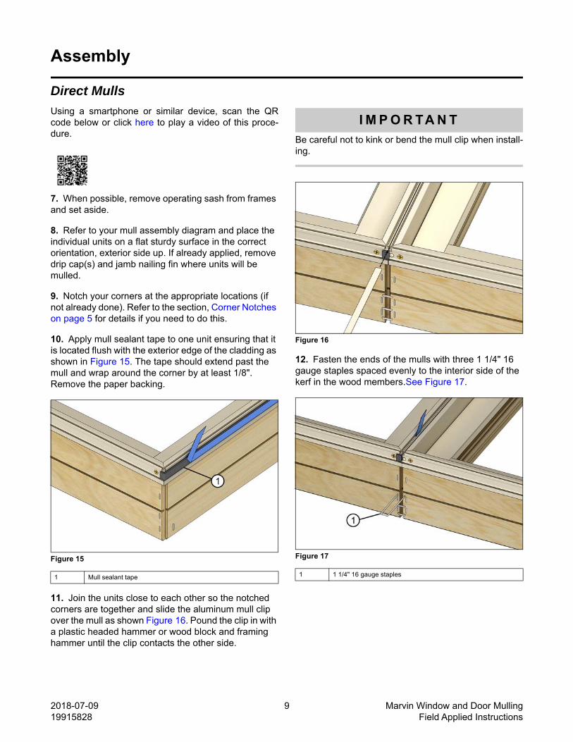
10. Apply mull sealant tape to one unit ensuring that it is located flush with the exterior edge of the cladding as shown in Figure 15. The tape should extend past the mull and wrap around the corner by at least 1/8". Remove the paper backing.
Figure 15
11. Join the units close to each other so the notched corners are together and slide the aluminum mull clip over the mull as shown Figure 16. Pound the clip in with a plastic headed hammer or wood block and framing hammer until the clip contacts the other side.
I M P O R TA N T
Be careful not to kink or bend the mull clip when install-ing.
Figure 16
12. Fasten the ends of the mulls with three 1 1/4" 16 gauge staples spaced evenly to the interior side of the kerf in the wood members.See Figure 17.
Figure 17
1 Mull sealant tape 1 1 1/4" 16 gauge staples

2018-07-09 10 Marvin Window and Door Mulling19915828 Field Applied Instructions
13. Carefully turn the assembly over, interior side up. Lightly clamp the units together on the wood frame members ensuring they are flush on the interior and even at the ends of the mull.
14. Fasten the units together with 5/8" x 1/2" staples as shown. Three staples spaced at 2" intervals must be placed on both ends, starting approximately 2" from the edge of the frame. Space the remaining staples at 5-8" intervals. See Figure 18.
Figure 18
Assembling 3/8" Aluminum Mull Reinforcement (MRF)
Using a smartphone or similar device, scan the QRcode below or click here to play a video of this proce-dure.
15. Set the units on a flat surface interior side up. Hook the MRF pieces together. Align the frames so they are flush and the ends are even. You may need to seat the assembly together with a rubber mallet. Secure the MRF with #8 x 5/8" undercut head screws through the pre-drilled interior face of the beige component. See Figure 19.
Figure 19
1 3 staples with 2" spacing at ends, 5-8" between ends
1 #8x5/8" undercut head screws

2018-07-09 11 Marvin Window and Door Mulling19915828 Field Applied Instructions
Assembling LVL and Wood Space Mulls-Vertical
H i n t
Remove the interior covers/stops where mulls will takeplace.
1. Set the units on a flat surface interior side up. Apply adhesive in a wiggle pattern on the window frame. See Figure 20.
Figure 20
2. Clamp the LVL member to one of the units flush with the interior. Fasten the LVL to the unit with #8 x 1 1/4" screws from the interior 4"(102) and 12-15" (305-381) on center (same plane as the jamb screw holes). See Figure 21.
Figure 21
3. Apply adhesive in a wiggle pattern on the LVL or space mull. See Figure 22.
Figure 22
4. Clamp the two units together and repeat screwing through the jambs as before.See Figure 23
Figure 23
5. Proceed to section, "Mull Cover Application".
1 4" (102)
2 12-15" OC (305-381)
3 #8x 1 1/4" screw
Vertical Space Mull Fastener Lengths
Mull Width Fastener Length
3/8" 1"
1" 2"
2" 3"
3" 4"
4" 5"

2018-07-09 12 Marvin Window and Door Mulling19915828 Field Applied Instructions
Assembling LVL and Wood Space Mulls-Horizontal
H i n t
Remove the interior covers/stops where mulls will takeplace. You will be screwing through the jambs/sills/headjambs to fasten to lvl or blocking.
1. Set the units on a flat surface interior side up. Apply adhesive in a wiggle pattern on the sill of the window frame of the top unit.See Figure 24
Figure 24
2. (CUDHNG and CUGL, skip to next step)Clamp the space mull block or LVL to the bottom of the upper unit flush with the interior. Fasten through the sill into the block with #8 2/3 thread screws 4" (102) from each end and every 12-15" (305-381) after (follow fastener length from table below). See Figure 25.
Figure 25
3. On CUDHNG and CUGL Horizontal Mulls, clamp the space mull block flush with the interior of the top unit and fasten through the block into the sill with #8 2/3 thread screws 4" (102) from each end and every 12-15" (305-381) after. See Figure 26. (See table below for proper length)
Figure 26
Horizontal Space Mull Fastener Lengths
Mull Width Fastener Length
3/8" 1"
1" 2"
2" 3"
3" 4"
4" 5"
1 4" (102)
2 12-15" OC (305-381)
Horizontal Fastener Lengths (CUDHNG & CUGL)
Mull Width Block to SillHead Jamb to
Block
3/8" 1" 1 3/4"
1" 2" 2 1/2"
2" 3" 2 1/2"
3" 4" 2 1/2"
4" 5" 2 1/2"

2018-07-09 13 Marvin Window and Door Mulling19915828 Field Applied Instructions
4. Apply adhesive in a wiggle pattern on the LVL or space mull. See Figure 27.
Figure 27
5. Clamp the two units together and screw through the head jamb and into the blocking above 4" from each end and 12-15" on center after.See Figure 28
Figure 28
6. On double hung units, remove the head jamb parting stop (on double hung operator units) from the bottom unit or stops from other Then drive #8 2/3 thread screws through the head jamb and into the space mull block. See Figure 29.(See fastener table above for proper length).
Figure 29 Remove parting stop on double hungs
NOTE: Make sure to place fasteners going through thehead jamb offset about 1" from those fastening theblock to the sill of the upper unit.
7. Replace the stops you removed earlier.
1 4" from each end and 12-15" after through block into sill
2 Fasten screws through head jamb into block 4" from each endand 12-15" after

2018-07-09 14 Marvin Window and Door Mulling19915828 Field Applied Instructions
Mull Cover Application
Frame Prep
1. With the assembly facing exterior up, make sure the corner notches are made in the right places. Refer to the previous section"Corner Notches" for details.
2. Apply frame kerf weatherstrip in the accessory kerf along the mullion and all open kerfs that run perpendicular to the mull. Roll the weatherstrip into the kerf with a screen spline roller or similar tool. See Figure 30.
Figure 30
3. If not done already cut two pieces of A148 frame trim. Measure the outside frame measurement and subtract 5/32” (4) for the finished length. Set these aside until sealant application is complete. See Figure 31.
Figure 31
4. If not done already cut the mull covers to length. Measure to the inside of the accessory kerf. Set these aside until sealant application is complete.See Figure 32.
Sealant Application-3/8" MRF
1. Apply 3/4" foam backer rod to the full length of the mullion. See Figure 33.
Figure 33
1 Outside width minus 5/32"
1 3/4" backer rod

2018-07-09 15 Marvin Window and Door Mulling19915828 Field Applied Instructions
2. Apply a 1/8" bead of clear sealant 2-3" long on each end of the mull and at any intersections along both edges of the mull.See Figure 34.
Figure 34
Sealant Application-Space Mulls
1. Apply a u-shaped bead of sealant over the ends of the space mull block. Press the foam block into place (notched side down) and apply additional beads of sealant on top. See Figure 35.
Figure 35
2. Apply a 1/8" bead of clear sealant 2-3" long in the accessory kerf on each end of the mull and at any intersections along both edges of the mull. See Figure 36.
Figure 36
1 Sealant at mull ends
2 Sealant at intersections
1 Sealant
2 Foam block (notched side down)
3 Space mull block/LVL
4 Sealant on top sides and outer edge of foam block
1 Sealant
2 A148 Frame trim (applied in next step)
3 Space mull cover (applied in next step)

2018-07-09 16 Marvin Window and Door Mulling19915828 Field Applied Instructions
Mull Cover Application
1. Use a plastic headed hammer to make minor dents in the cladding accessory kerf where the A148 frame trim will be applied. The frame trim will always run perpendicular to any non-direct mull. See Figure 37.
Figure 37
H i n t
Avoid "over-denting" the edges of the frame and use theside of the plastic headed hammer.
2. Apply the A148 frame trim to the assembly at each end of a non-standard (direct) mull. Pound the trim on with a plastic headed hammer or block of wood and framing hammer. See Figure 38.
Figure 38
3. Apply the mull cover by inserting one end into the frame kerf and tapping the cover into place with a plastic headed hammer or rubber mallet the first 6-10" from the end. Then insert the opposite end into the frame kerf and tap into place along the length of the mull. See Figure 39.
Figure 39 (A148 frame trim removed for illustrative purposes,MRF shown, similar on other space mull applications)
Multi High/Multi Wide Assemblies
1. Mull clips are sent cut to length for one high or one wide assemblies. On multi high multi wide assemblies all clips are sent long and you will need to cut them to fit.
2. Mull all direct assemblies first.
3. Mull space mulls, MRFs and LVLs last.
1 A148 frame trim

2018-07-09 17 Marvin Window and Door Mulling19915828 Field Applied Instructions
Install Field Applied CasingsRefer to the following instructions for information onhow to apply BMC or Flat Casing in the field. Visitwww.marvin.com/support/technical-resources andsearch for the following instructions:
• Rectangular BMC Instructions for Windows and Doors 11708096
• Clad Flat Casing Instruction 19913125
• Clad Polygon BMC Instruction 11708097
• Clad Round Top BMC Instruction 11708561
Figure 40