Embed Size (px)
Citation preview
8/20/2019 1997 Perfect Reconstruction Circular Convolution Filter Banks and Their Application to the Implementation of Bandl…
http://slidepdf.com/reader/full/1997-perfect-reconstruction-circular-convolution-filter-banks-and-their-application 1/4
PERFECT RECONSTRUCTION CIRCULAR CONVOLUTION FILTER BANKS AND
THEIR APPLICATION TO THE IMPLEMENTATION
O F
BANDLIMITED
DISCRETE WAVELET TRANSFORMS
A j i t .
S.
Bopardikar' Mysore.
R .
Raghuveer'
B.
S. Adiga'
'Center for Imaging Science/Electrical Engineering Dept.
Rochester Institute of Technology
Rochester, NY
USA
2Motorola India Electronics Ltd.
Bangalore
Karnataka, India.
ABSTRACT
This paper, introduces a new filter bank structure called
the perfect recon struct ion circular convolut ion (PRCC) fil-
ter bank. These filter banks satisfy the perfect reconstruc-
tion properties, namely, the paraunitary properties in the
discrete frequency domain. We further show how the PRCC
analysis and synthesis filter banks are completely imple-
mented in this domain and give
a
simple and a flexible
method for the design of these filters. Finally, we use this
filter bank structure for a frequency sampled implementa-
tion of the discrete wavelet transform based on orthogonal
bandlimited scaling functions and wavelets.
1 INTRODUCTION
In this paper we present a new multirate filter bank struc-
ture which we call
perfect rec onstruc t ion circular convolu-
t ion (PRCC) filter bank. We fur ther develop simple and
flexible methods for designing these filters t o specification.
The formulation of this new filter bank structure has been
motivated in pa rt by the search for efficient methods to im-
plement the discrete wavelet transform (DWT) based on
orthogonal bandlimited scaling functions and wavelets. A
considerable amount of research has been done in the area
of wavelets that are compactly supported in time. However,
there are situations where a bandlimited scaling function or
wavelet could be more appropriate. Relevant examples can
be found in a variety of fields such as communication, sig-
nal analysis and pattern recognition [2,
5 ,
71. We provide
another example of such a situation in section 3 . Bandlim-
ited wavelets and scaling functions have several interesting
properties. For example, they provide an easy solution set
to th e problem of designing orthonormal multiresolution de-
composition, generating wavelets that are matches to arbi-
trarily specified signals
[ 5 ,
41. Using such wavelets Samar
et. al.
[7J
have shown superior convergence
of
multiresolu-
tion representations for bandlimited wavelets
as
compared
to wavelets with compact time support for
EEG
data.
An impediment to more widespread use of bandlimited
wavelets has been their infinite time support that makes
the corresponding filters of infinite impulse response (IIR)
type, usually without a finite order difference equation. To
get around this, an appropriately truncated version of the
time response can be used.
This
results in loss of the ban-
dlimitedness property. For the DWT, it also means a loss
of invertibility and perfect reconstruction. Here, we intro-
duce a filter bank st ructure that pTovides a framework for a
frequency sampled implementation of bandlimited scaling
functions and wavelets ,while guaranteeing perfect recon-
struction at the same time.
The paper is organized as follows. Section 2 describes
the Meyer scaling function. Section
3
illustrates a sce-
nario where the Meyer scaling function or its generaliza-
tion could be an optimal choice. Section
4
describes the
PRCC framework and presents a simple and flexible method
for the design of these filters. Section 5 explains how the
PRCC framework could be used for the frequency sampled
implementation of bandlimited wavelet transform. Section
6 explains the symmetric extension implementation of the
PRCC filter banks to reduce edge effects. Finally, section 7
presents the conclusion.
2 T H E MEYER SCALING FUNCTION
As mentioned above, in this paper, we will show how the
PRCC filter bank structure can be used for a frequency
sampled implementation of the DWT based on orthogonal
scaling functions and wavelets. It
has
been shown that a
generalized version of the Meyer class of scaling functions
are the only bandlimited functions which define
a
orthogo-
nal multiresolution analysis [4]. n other words,
all
orthog-
onal bandlimited scaling functions and wavelets belong to
a generalized version of the Meyer class.
The Meyer scaling function,
d ( t )
satisfies the following
properties [4]:
1. The spectrum of d t ) , @ U) is bandlimited to
I
w
I
4x/3.
4. The Poisson sum,
I @ U+ 2 x k ) 12=
1
This is
equivalent to ( d ( t ) , d ( t- n))
= 6(n)
In other words,
the Meyer s c J n g function
is
orthogonal t o it s integer
translates .
k
3
MOTIVATION
This section illustrates a situation where the Meyer scaling
function could naturally arise in the context of sampling a
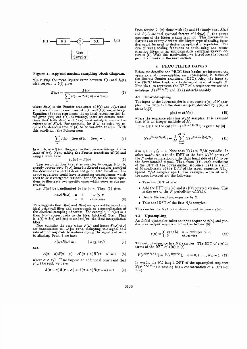
bandlimited function. Consider the system shown in figure
1. This corresponds to an approzimation sampling proce-
dure. Here, a t is
an
anti-aliasing filter.
This
is
followed
now ask the following questions: Given a signal f t ) , oes
there exist an optimal pair
a t ) ,
b ( t ) , which minimizes the
mean square error between the original signal
f
t )
and its
approximation
fa t)?
If yes, what are the properties that
this pair satisfies?
by a uni t - samp r and b ( t )
is
the reconstruction filter. We
Now, from Figure 1,
This corresponds to unit sampling of g t ) . Using (1) we
have
n
0-8186-7919-0/97 $10.00 1997 IE EE
3665
8/20/2019 1997 Perfect Reconstruction Circular Convolution Filter Banks and Their Application to the Implementation of Bandl…
http://slidepdf.com/reader/full/1997-perfect-reconstruction-circular-convolution-filter-banks-and-their-application 2/4
Unit
Figure
1.
Approximation sampling block diagram.
Minimizing the mean square error between f 2 ) and fa t)
with respect to b t ) gives
where B ( w is the Fourier transform of b t ) and
A w)
and
Equation 3) thus represents the optimal reconstruction fil-
ter given
j ( t )
and
a
t ) .
Obviously, there are certain condi-
tions that both A(w\ and F ( w ) must satisfy to ensure the
existence of
B(w).
For example, for B w) o exist, we re-
quire the denominator of 3) to be non-zero a t all w . With
this condition, the Poisson sum
F ( w ) are
F’
ourier transforms of a ( t ) and
f ( t )
espectively.
A ( w + 2xn)B(w
+
2x72) =
1
4)
n
In words,
a ( - t ) is
orthogonal t o the non-zero interger trans-
lates of
b ( t ) .
Now, taking the Fourier transform
of
2) and
using
3)
we have
Fa w)= F ( w )
5 )
This result implies that it is possible to design B ( w ) o
exactly reconstruct F ( w ) from i ts filtered samples provided
the denominator in
3)
does not
go
to zero for all
w .
The
above equations could have interesting consequences which
need to be investigated fur the r. For now, we use these equa-
tions to illustrate two specific cases which serve as our mc-
tivation.
Let
F ( w )
be bandlimited to I w
I
x . Then,
3)
gives
A ( w ) B ( w ) = 1 I w 157
This suggests that A ( w ) and B ( w ) are spectral factors of the
ideal brickwall filter and corresponds to a generalization of
the classical sampling theorem. For example, if A ( w ) = 1
then B ( w ) corresponds to the ideal brickwall filter. Th at
is,
a t )
= 6 t )
and b t )
=
sin( xt) /xt, the ideal interpolation
iilter.
Now consider the case when
F ( w )
and hence F ( w A ( w )
are bandlimited to
I
w
I=
4 x / 3 . Sampling this
s i gna
at a
rate
of
1 corresponds to undersampling the signal and leads
to aliasing. From
3
we have
6)
0 otherwise
From section
2,
9) along with
7 )
and 4) imply that A ( w )
and
B ( w )
are real spectral factors of Q
w
12 the power
lustrates an example where the Meyer type of scaling func-
tion could be used to derive an optimal interpo lator. The
idea of using scaling functions
as
antialiasing and recon-
struction filters
in
an approximation sampling system oc-
curs in
[I].
With this motivation, we introduce the idea of
prcc filter banks
in
the next section.
spectrum
of
the Meyer scaling function.
1
is discussion il-
4 PRCC FILTER
BANKS
Before we describe the PR CC filter banks, we interpret the
operations
of
downsampling and upsampling in terms
of
the discrete Fourier transform (DFT).
Also,
the input to
the PRCC filter bank is a finite signal z ( n ) of length N .
Note that, to represent the DFT of a sequence we use the
notations X (eJZrk”) and X
(k)
nterchangeably.
4.1
Downsampling
The input to the downsampler is a sequence
z n)
of
N
sam-
ples. The output of the downsampler, denoted by y f n ) , is
given by[8]
where the sequence
y(n)
has
N / M
samples. It is assumed
that N is an integer multiple of
M .
The
DFT
of the output
Y ( eJ2 xk ’ ( N ’ M) )
s given by
131
d n = 4 M n ) 10)
M - 1
k = 0,1,. . , -
1.
Note that Y ( k ) s N / M periodic. In
other words, we take the IDFT of the first
N / M
points of
the N point summation on the right hand side of 11) to get
the downsampled signal. Thus, from l l ) , ach coefficient
of the DFT of the downsampled sequence
Y ( k )
s a sum
of M coefficients of the DFT of the input sequence X ( k ) ,
spaced
N / M
samples apart . For example, when
M
= 2 ,
the steps involved are the following:
Take the DFT of z n)
Add the
DFT
of z ( n )and its N / 2 rotated version. This
Divide the resulting sequence by
2.
Take the I DF T of the first
N /2
samples.
makes use of the N periodicity of X ( k ) .
This creates the
N / 2
point dowsampled sequence y n ) .
4.2 Upsampling
An L-fold upsampler takes an input sequence z n) and pro-
duces an output sequence defined
as
follows
[8]:
12)
n / L )
n = multiple of
L
y n)=
{
0
otherwise
A ( w ) B ( w )
= 1 I I5 2 x 1 3 7)
The output sequence
has N L
samples. The
DFT
of
y(n)
in
and
terms of the DFT of
z n) s
[3]
Y ( e J Z n k / ( N L ) )X ( e J Z n ’ k / N ) ,
.
-
Y)B(T
Y) +
A 8 x
+ (Y)B’(*+
Y)
= 1
8)
where
Y <
7r/3.
If we impose an additional constraint that
F ( w )
be real, we have
k =
0,1,.
. . ,N L
- 1
( 1 3 )
In words, the N L length DFT of the upsampled sequence
Y(eJZrk / (NL) )
s nothing but
a
concatenation of
L
DFTs
of
A(“ - ~ ) B ( xa)
+
A . a)B *
+a )
= 1
9) ~ n ) .
3666
8/20/2019 1997 Perfect Reconstruction Circular Convolution Filter Banks and Their Application to the Implementation of Bandl…
http://slidepdf.com/reader/full/1997-perfect-reconstruction-circular-convolution-filter-banks-and-their-application 3/4
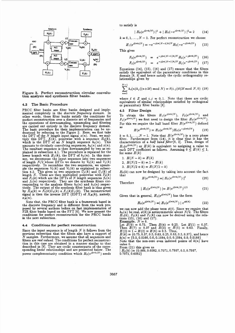
Figure 2. Perfect r econs t ruc t ion
circular
convolu-
tion analysis and synthesis
filter banks.
4.3 The
Basic
Procedure
PRCC filter banks are filter banks designed and imple-
mented completely in the
discrete
frequency
domain.
In
other words, these filter banks satisfy the conditions for
perfect reconstruction over a discrete set of frequencies and
the operations of downsampling, upsampling and filtering
are carried out entirely in the discrete frequency domain.
The basic procedure for their implementation can be un-
derstood by referring to the Figure 2 .
Here, we first take
the DFT of the N length input signal
z n).
Next, we mul-
tiply this DFT, X ( k ) , pointwise with
a
sequence
H o
k
which is the D FT of an N length sequence ho n). l hk
amounts to circularly convolving sequences,
ho n)
nd z
n).
The resultant sequence is then downsampled by two
as
ex-
plained in subsection 4.1. The procedure is repeated for the
lower branch with Hl k),he DFT of
hl (n) .
In this man-
ner, we decompose the input sequence into two sequences
of length N / 2 whose DFTs we denote by Vo(k) and Vl(k)
respectively. To recombine the two sequences, we upsam-
responding to the analysis filters ho(n) and h l (n ) respec-
tively. The output of the synthesis filter bank
is
thus given
by X R ( ~ )
Fo k)Uo k) FI
k ) U 1
k .
The reconstructed
signal is then the inverse DFk (ID
L
of
X R ( ~ ) ,
amely,
Z R n ) .
Note that, the PRCC filter bank
is
a framework based in
the discrete frequency and
is
different from the work pro-
posed by several authors before on fast implementation of
FIR filter
banks
based on the FFT
[ 6 ] .
We now present the
conditions for perfect reconstruction for the PRCC banks
in the next subsection.
4.4
Conditions for
perfect reconstruction
Since the input sequence is of length
N it
follows from the
previous subsection that the filters also have a support of
N samples. Furthermore, we assume th at
a l l
sequences and
filters are real valued. The conditions for perfect reconstruc-
tion in
this
case are obtained in a manner similar
to
that
described in
[8].
They are cyclic counterparts of the corre-
sponding linear relationships and are presented below. The
power complementarity condition which Ho e J Z r k l N )needs
to satisfy
is
I
~ ~ ( e ~ ~ ~ ~ l ~ )
+
I ~ o ( - - e ~ ' ~ l ~ )2 = 2
14)
15)
)
16)
( 1 7 )
k
= 0,1,. . ,N - 1. For perfect reconstruction we choose
H ,
e J 2 r k / N )
= _ e - J 2 x N - - l ) k / N ~ o _ e - 3 2 x k / N
)
This gives
e - ~ 2 ~ - l ) k / N ~ ~ ( ~ - J 2 x k / N
F I ( e J Z n k f N )
= e - 3 2 x ( N - l ) k / N ~ 1 e - ~ Pr k / N
F ~ ( ~ J Z X ~ / N
=
Equations 14),
15) ,
( 1 6 ) and ( 1 7 ) ensure that the filters
satisfy the e uivalent of the paraunitary conditions in this
domain
[8, 37
and hence satisfy the cyclic orthogonality re-
lationsliips given by
N-I
h , ( n ) h 3 ( ( n + 2 ) mod
N )
= 6(i, ) 6 ( 2 mod N,O) 18)
where
L E
and i j = 0 , l . Note that these are cyclic
equivalents of similar relationships satisfied by orthogonal
or paraunitary filter banks
[8].
4.5
Filter
Design
To obtain the filters
H l ( e J Z x k l N ) , F o ( e J Z r k l N )
and
F l ( e J Z T k l N )
e first need to design the filter H o ( ~ ~ ~ ~
For this we require the half band filter H ( e J 2 x k l N ) efined
n O
as
H ( ~ 2 x k / N )= H~ e J 2 r k / N ) ~ 0 (- J 2 r k / N
19)
k = 0,1,
..
. ,N - 1. Note that H ( e J 2 r k l N )s a zero phase
filter. Furthermore from
14),
t is clear that
it
has the
characteristics of a half bond f i l t e r [8 , 31. Thus, design of
~ l ( e 3 ~ ~ ~ l ~ )r H ( k ) is equivalent to assigning a value to
each
DFT
coefficient as follows. Assuming
0 5
H ( k )
5 1,
for some H ( k )
1 . H ( N
-
) = H ( k )
2 , H ( N / 2- ) z.1- H ( k )
3 .
H ( N / 2
+
k )
=
H ( N / 2
-
)
Ho k) an now be designed by taking into account the fact
that
Therefore
( 2 0 )
2 1 )
3 2 x k / N ) 12
H( eJ2nk ) =I Ho( e
I
~ ~ ( ~ 1 2 r k l N )=H ( ~ J ~ ~ / N/ 2
Given that
in
general, & ( e 3 2 k / N ) has the form
( 2 2 )
o ( e l ' * ~ )
=I H o ( e
2 v k l N ) I e ~ + t k )
we can now add the phase term
q?J t).
ince we require that
ho(n)be real,
q?J(k)s
antisymmetric about N / 2 . Th e filters
Hl k),o ( k ) and FI ) can now be derived using the rela-
tions 15). 116) and i 7 ) .
\ \ I
E x d p l e .
N =
8.
Let
H
0)
=
0.75.
Then
H
4
=
0.25.
Let
H ( 1 )
=
0 .37 .
Then
f i ( 7 )
=
0.37
and
H ( 3 ) = H 5)= 0 . 6 3 .
Finally,
H [ k ) =
{ 0 . 7 5 , 0 . 3 7 , 0 .5 , 0 . 6 3 , 0 . 2 5 ,0 . 6 3 , 0 . 5 , 0 . 3 7 },
and hence
h (n )
=
~0.5.0.0166,0.0,0.1084.0.0,0.1084,0.0,0.0166~
H 2 = 1
-
H ( 2 ) = H ( 6 ) = 0 .5 . Thus,
Notk th&t the nonizero even indexed points 'of
h(nf
have
value
0.
From 21) this gives us
I Ho k) { 0 . 8 6 6 , 0 . 6 0 8 2 , 0 . 7 0 7 1 , 0 . 7 9 3 7 , 0 . 5 , 0 . 7 9 3 7 ,
0 . 7 0 7 1 , 0 . 6 0 8 2 }
3667
8/20/2019 1997 Perfect Reconstruction Circular Convolution Filter Banks and Their Application to the Implementation of Bandl…
http://slidepdf.com/reader/full/1997-perfect-reconstruction-circular-convolution-filter-banks-and-their-application 4/4
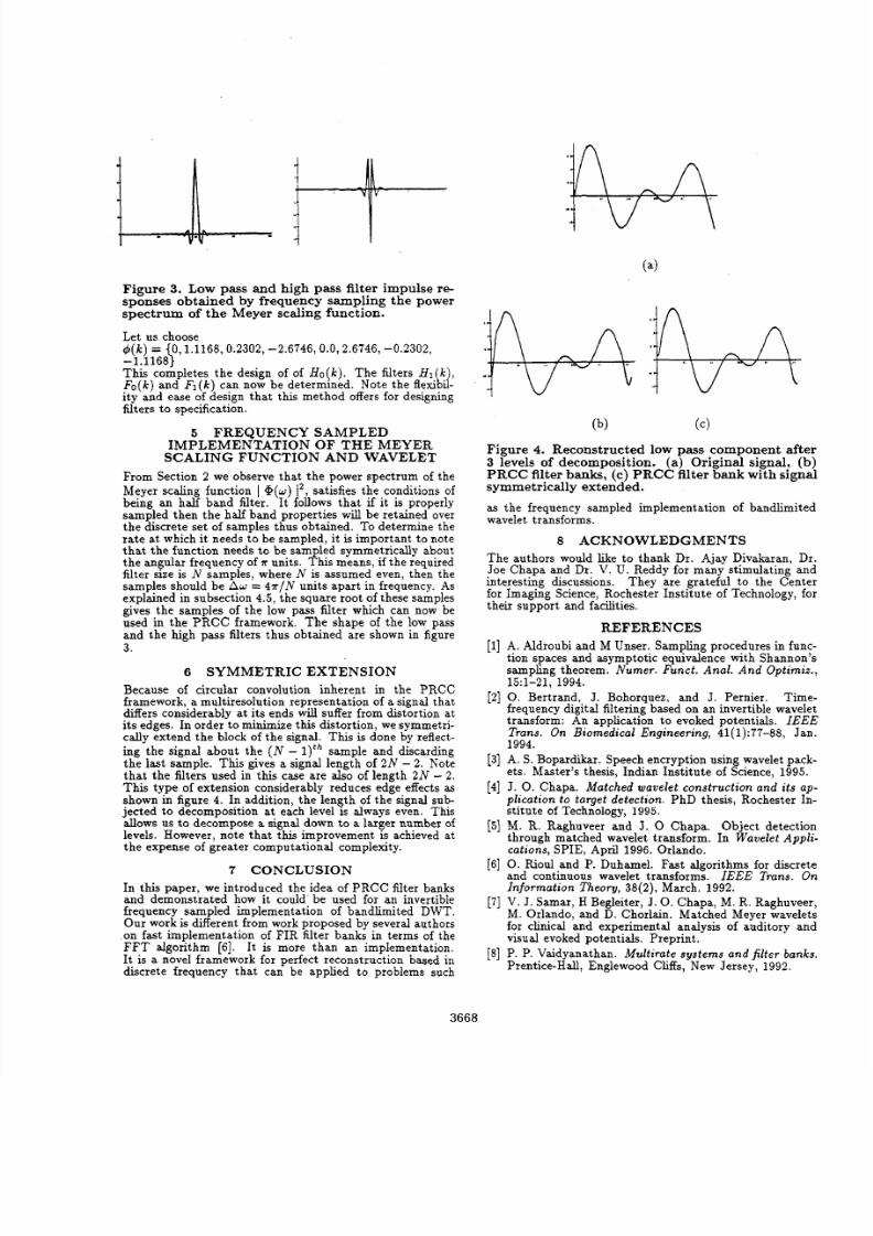
Figure 3 Low
pass and
h igh pass filter impulse
re-
sponses obtained b y frequency sampling
the
power
spectrum
of the
Meyer
scaling
function.
Let us choose
-
.1168\
This completes the design of of Ho k). he filters
H I
k
Fo k)
nd Fl k) an now be determined. Note the flexikk
ity and ease of design that this method offers for designing
filters to specification.
5 F R E Q U E N C Y
SAMPLED
(k)
=
0,1 .11 68,0 .23 02, -2 .6746 ,0 .0 ,2 .67 46, -0 .2302,
I M P L E M E N T A T I O N OF THE MEYER
SCALING
F U N C T I O N
AND WAVELET
From Section
2
we observe that the power spectrum of the
Meyer scaling function I @ ( U ) 12 satisfies the conditions of
being an half band filter. It follows that
if
it is properly
sampled then the half band properties will be retained over
the discrete set of samples thus obtained. To determine the
rat e at which it needs to be sampled, it is important to note
th at the function needs to be sampled symmetrically about
the angular frequency of 7r units.
This
means, if the required
filter size is N samples, where N is assumed even, then the
samples should be A w = 4 x / N units apart in frequency. As
explained in subsection 4 . 5 , the square root of these samples
gives the samples of the low
pass
filter which can now be
used in the PRCC framework.
The
shape of the low pass
and the high pass filters thus obtained are shown in figure
3.
6
SYMMETRIC E X T E N S I O N
Because of circular convolution inherent in the PRCC
framework,
a
multiresolution representation of a signal that
differs considerably at i ts ends will suffer from distortion at
its
edges. In order to minimize this dis tortion, we symmetri-
cally extend the block of the signal.
This
is done by reflect-
ing
the signal about the ( N -
) t h
ample and discarding
the last sample. This gives a signal length of
2 N - .
Note
that the filters used in this case are also of length 2 N - 2.
This type of extension considerably reduces edge effects
as
shown in figure 4. In addition, the length of the signal sub-
jected
to
decomposition a t each level is always even. This
allows
us
to decompose
a
signal down to a larger number of
levels. However, note that this improvement is achieved at
the expense of greater computational complexity.
7
CO N CLU S I O N
In this paper, we introduced the idea of PRCC filter banks
and demonstrated how it could be used for an invertible
frequency sampled implementation of bandlimited DWT.
Our work is different from work proposed by several authors
on fast implementation of FIR filter banks in terms of the
FFT algorithm [6 ] . It is more than an implementation.
It is a novel framework for perfect reconstruction based in
discrete frequency that can be applied to problems such
(b) (c)
Figure 4. Reconstructed low pass component after
3
levels
of decomposition. a) Original signal, (b )
PRCC
filter banks, (c) PRCC filter
bank with signa
symmetrically
extended.
as the frequency sampled implementation of bandlimited
wavelet transforms.
8
A C K N O W L E D G M E N T S
The authors would like to thank Dr. Ajay Divakaran, Dr.
Joe Chapa and Dr. V.
U.
Reddy for many stimulating and
interesting discussions. They are grateful to the Center
for Imaging Science, Rochester Institute of Technology, for
their support and facilities.
R E F E R E N C E S
[l] A. Aldroubi and
M
Unser. Sampling procedures in func-
tion spaces and asymptotic equivalence with Shannon's
sampling theorem.
Nu mer . Fu n c t . An al. An d Opt i mi z .
Time
frequency digital filtering based on an invertible wavelet
transform: An application to evoked potentials. I E E E
Trans. On Biomedical Engineering,
41 1):77-88, Jan
1994.
[3] A.
S.
Bopardikar. Speech encryption using wavelet pack-
ets. Master's thesis, Indian Institute of Science,
1995.
[4] J .
0.
Chapa.
Matched wavelet construct ion and i t s ap-
pl icat ion to target detect ion . PhD thesis, Rochester In-
stitute of Technology, 1995.
[5]
M.
R.
Raghuveer and J .
0
Chapa. Object detection
through matched wavelet transform. In
W ave l e t Appl i
cat ions , SPIE, April 1996. Orlando.
[6] 0.
Eoul and P. Duhamel. Fast algorithms for discrete
and continuous wavelet transforms. IEEE T ran s . On
In format i on T h eory ,
38 2) , March. 1992.
[7] V. J. Samar, H Begleiter, J. 0.Chapa, M. R. Raghuveer
M. Orlando, and
D.
Chorlain. Matched Meyer wavelets
for clinical and experimental analysis of auditory and
visual evoked potentials. Preprint.
[8] P.
P.
Vaidyanathan. Multirate systems and fi l ter banks
Prentice-Hall, Englewood Cliffs, New Jersey, 1992.
15:1-21, 1994.
[2] 0 Bertrand,. J. Bohorquez, and
J .
Pernier.
3668