Embed Size (px)
Citation preview
PART NO. 37-75691504
1F83H-21NP (Non-Programmable)Installation and Operating Instructions
80 Series Heat Pump ThermostatBattery Powered or Hardwired with Common
emersonthermostats.comwhite-rodgers.com
Thermostat Applications Maximum
Stages Heat /Cool
Single Stage Compressor, Heat Pump Systems (air source or geothermal) – 1 Stage Aux/Emergency Heat
2/1
Thermostat Installation 2-4
Wiring 2
Installer Menu 3-4
Using the Thermostat 5-6
Thermostat Overview 5
User Menu 6
Troubleshooting 7-8
Homeowner Help Line 8
INDEX
MERCURY NOTICE: This product does not contain mercury. However, this product may replace a product
that contains mercury. Mercury and products containing mercury must not be discarded in household trash.
Refer to www.thermostat-recycle.org for information on disposing of products containing mercury.
Electrical Rating:Battery Power ..................................... 20 to 30 VAC, NEC Class II, 50/60 HzInput-Hardwire .................................... 20 to 30 VAC, NEC Class II, 50/60 Hz
Terminal Load .......................................... 1.5 A per terminal, 2.5A maximum all terminals combined Setpoint Range ........................................ 45° to 99° F (7° to 37° C)Rated Differentials (@ 6°F/ Hr): Fast Med Slow
Heat Pump (Heat)................................ 0.9°F 1.2°F 1.7°FHeat Pump (Cool) ................................ 0.9°F 1.2°F 1.7°FAuxiliary Heat ...................................... 0.5°F 0.75°F 1.9°F
Operating Ambient .................................. 32°F to +105°F (0° to +41°C) Display Temperature Range ....................... 32°F to +99°F (0 to 37°C)Operating Humidity ................................. 90% non-condensing maximum Shipping Temperature Range ................... -20°F to + 150°F (-29° to +65°C)Thermostat Dimensions ........................... 3-3/4” H x 6” W x 1-1/8” D
SPECIFICATIONS
Optional Accessory: Wall Cover-up Plate F61-2663, 6 3/4” W x 4 1/2” H
2
Terminal Designations Terminal FunctionR Power (24V)
O/B Changeover Terminal-Energized in Cool (O) or Heat (B) for Heat Pump or Damper Systems
Y Heat and Cool Mode 1st Stage Compressor
G Fan Relay
E* Auxiliary only Heat Mode (Emergency Heat)
C Common wire for 24V (optional with batteries)
L Heat Pump malfunction / Diagnostic terminal (input signal requires common)
W2* Heat Mode – 2nd stage
*Cut W2/E jumper when separate heat sources are used for W2 and E.IMPORTANT: For Dual Fuel Heat Pump applications, be sure to turn on the Duel Fuel Logic option (found in the Installer’s Menu)
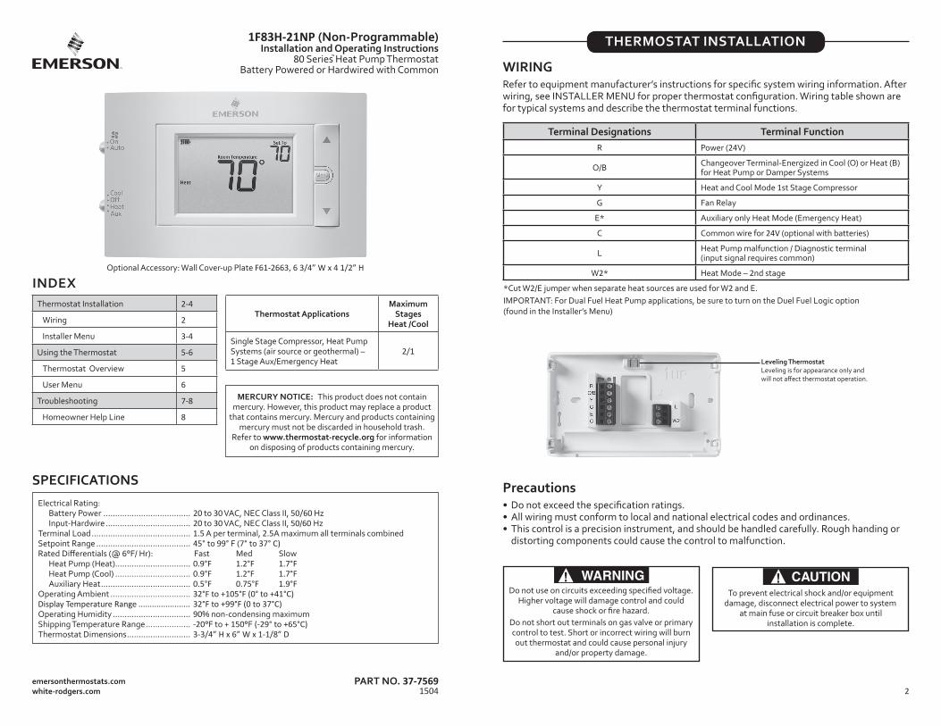
WIRING Refer to equipment manufacturer’s instructions for specific system wiring information. After wiring, see INSTALLER MENU for proper thermostat configuration. Wiring table shown are for typical systems and describe the thermostat terminal functions.
THERMOSTAT INSTALLATION
Precautions• Do not exceed the specification ratings.• All wiring must conform to local and national electrical codes and ordinances.• This control is a precision instrument, and should be handled carefully. Rough handing or
distorting components could cause the control to malfunction.
WARNING!Do not use on circuits exceeding specified voltage.
Higher voltage will damage control and could cause shock or fire hazard.
Do not short out terminals on gas valve or primary control to test. Short or incorrect wiring will burn out thermostat and could cause personal injury
and/or property damage.
CAUTION!To prevent electrical shock and/or equipment
damage, disconnect electrical power to system at main fuse or circuit breaker box until
installation is complete.
Leveling ThermostatLeveling is for appearance only and will not affect thermostat operation.
3
INSTALLER MENU To prevent changes that may affect system performance, this thermostat has an INSTALLER’S MENU and a USER MENU. The INSTALLER’S MENU provides access to every option, while the USER MENU provides access to items that will not affect system performance. To access the INSTALLER’S MENU press the Menu button for 8 seconds. The display will show item 30 in the table below. Use Next to navigate through menu items. Press or to change a menu setting.
Installer’s Menu #(Hold Menu 8 Seconds)
Description Default Setting (flashing icons)
Settings (Press or )
30 Heat Cycle Rate (how often the heat will turn on) MEd
SLO – slowMEd – mediumFAS – fast
32 Aux Cycle Rate (how often the auxiliary heat will turn on) MEd
SLO – slowMEd – mediumFAS – fast
35 Cool Cycle Rate (how often the cooling will turn on) MEd
SLO – slowMEd – mediumFAS – fast
50 Compressor Lockout (protects the compressor from short cycling)
OFF On – 5 minute delay OFF – no delay
60 Duel Fuel Logic (turn On when using gas as the auxiliary heat source) OFF On- gas auxiliary heat
OFF- electric auxiliary heat
65 Maximum Heat Limit (maximum set point for heat mode) 99 47 to 99
66 Minimum Cool Limit (minimum set point for cool mode) 45 45 to 97
(Installer Menu continued on next page)
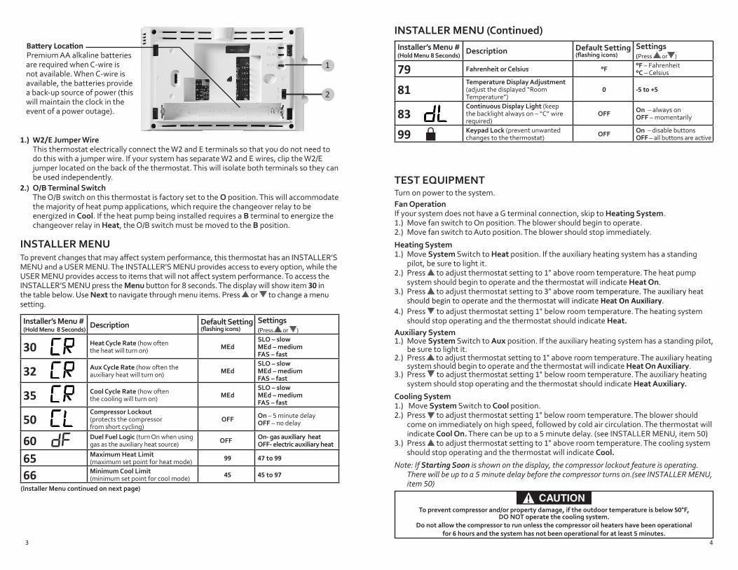
1.) W2/E Jumper Wire This thermostat electrically connect the W2 and E terminals so that you do not need to
do this with a jumper wire. If your system has separate W2 and E wires, clip the W2/E jumper located on the back of the thermostat. This will isolate both terminals so they can be used independently.
2.) O/B Terminal Switch The O/B switch on this thermostat is factory set to the O position. This will accommodate
the majority of heat pump applications, which require the changeover relay to be energized in Cool. If the heat pump being installed requires a B terminal to energize the changeover relay in Heat, the O/B switch must be moved to the B position.
Battery LocationPremium AA alkaline batteries are required when C-wire is not available. When C-wire is available, the batteries provide a back-up source of power (this will maintain the clock in the event of a power outage).
1
2
4
CAUTION!To prevent compressor and/or property damage, if the outdoor temperature is below 50°F,
DO NOT operate the cooling system. Do not allow the compressor to run unless the compressor oil heaters have been operational
for 6 hours and the system has not been operational for at least 5 minutes.
TEST EQUIPMENTTurn on power to the system. Fan Operation If your system does not have a G terminal connection, skip to Heating System. 1.) Move fan switch to On position. The blower should begin to operate. 2.) Move fan switch to Auto position. The blower should stop immediately.
Heating System1.) Move System Switch to Heat position. If the auxiliary heating system has a standing
pilot, be sure to light it.2.) Press to adjust thermostat setting to 1° above room temperature. The heat pump
system should begin to operate and the thermostat will indicate Heat On. 3.) Press to adjust thermostat setting to 3° above room temperature. The auxiliary heat
should begin to operate and the thermostat will indicate Heat On Auxiliary.4.) Press to adjust thermostat setting 1° below room temperature. The heating system
should stop operating and the thermostat should indicate Heat.Auxiliary System 1.) Move System Switch to Aux position. If the auxiliary heating system has a standing pilot,
be sure to light it.2.) Press to adjust thermostat setting to 1° above room temperature. The auxiliary heating
system should begin to operate and the thermostat will indicate Heat On Auxiliary. 3.) Press to adjust thermostat setting 1° below room temperature. The auxiliary heating
system should stop operating and the thermostat should indicate Heat Auxiliary.
Cooling System1.) Move System Switch to Cool position. 2.) Press to adjust thermostat setting 1° below room temperature. The blower should
come on immediately on high speed, followed by cold air circulation. The thermostat will indicate Cool On. There can be up to a 5 minute delay. (see INSTALLER MENU, item 50)
3.) Press to adjust thermostat setting to 1° above room temperature. The cooling system should stop operating and the thermostat will indicate Cool.
Note: If Starting Soon is shown on the display, the compressor lockout feature is operating. There will be up to a 5 minute delay before the compressor turns on.(see INSTALLER MENU, item 50)
Installer’s Menu #(Hold Menu 8 Seconds)
Description Default Setting (flashing icons)
Settings (Press or )
79 Fahrenheit or Celsius °F °F – Fahrenheit°C – Celsius
81 Temperature Display Adjustment (adjust the displayed “Room Temperature”)
0 -5 to +5
83Continuous Display Light (keep the backlight always on – “C” wire required)
OFF On – always onOFF – momentarily
99 Keypad Lock (prevent unwanted changes to the thermostat) OFF On – disable buttons
OFF – all buttons are active
INSTALLER MENU (C0ntinued)
5
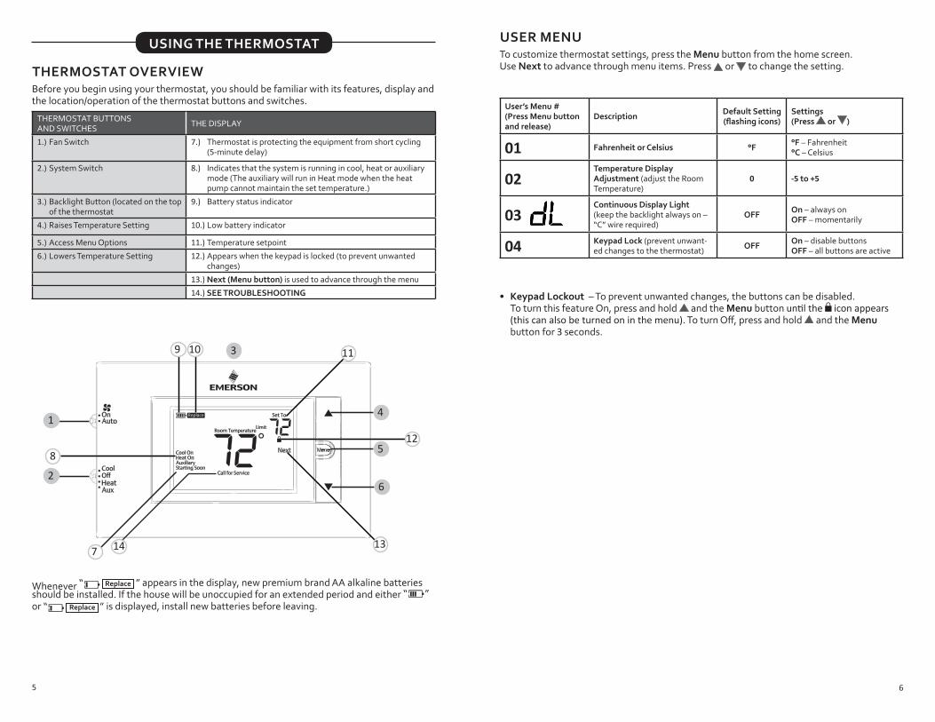
THERMOSTAT OVERVIEWBefore you begin using your thermostat, you should be familiar with its features, display and the location/operation of the thermostat buttons and switches.
THERMOSTAT BUTTONS AND SWITCHES THE DISPLAY
1.) Fan Switch 7.) Thermostat is protecting the equipment from short cycling (5-minute delay)
2.) System Switch 8.) Indicates that the system is running in cool, heat or auxiliary mode (The auxiliary will run in Heat mode when the heat pump cannot maintain the set temperature.)
3.) Backlight Button (located on the top of the thermostat
9.) Battery status indicator
4.) Raises Temperature Setting 10.) Low battery indicator
5.) Access Menu Options 11.) Temperature setpoint
6.) Lowers Temperature Setting 12.) Appears when the keypad is locked (to prevent unwanted changes)
13.) Next (Menu button) is used to advance through the menu
14.) SEE TROUBLESHOOTING
1
2
3
4
5
6
7
8
9 10 11
12
1314
USING THE THERMOSTAT
Whenever “ Replace ” appears in the display, new premium brand AA alkaline batteries
should be installed. If the house will be unoccupied for an extended period and either “ ” or “ Replace
” is displayed, install new batteries before leaving.
6
USER MENUTo customize thermostat settings, press the Menu button from the home screen. Use Next to advance through menu items. Press or to change the setting.
User’s Menu #(Press Menu button and release)
Description Default Setting (flashing icons)
Settings(Press or )
01 Fahrenheit or Celsius °F °F – Fahrenheit°C – Celsius
02Temperature Display Adjustment (adjust the Room Temperature)
0 -5 to +5
03 Continuous Display Light (keep the backlight always on – “C” wire required)
OFF On – always onOFF – momentarily
04 Keypad Lock (prevent unwant-ed changes to the thermostat) OFF On – disable buttons
OFF – all buttons are active
• Keypad Lockout – To prevent unwanted changes, the buttons can be disabled. To turn this feature On, press and hold and the Menu button until the icon appears
(this can also be turned on in the menu). To turn Off, press and hold and the Menu button for 3 seconds.
7
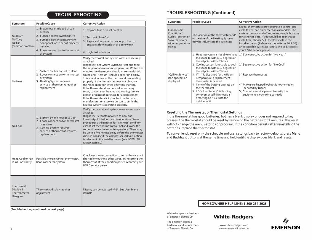
Symptom Possible Cause Corrective Action
No Heat/ No Cool/No Fan (common problem)
1.) Blown fuse or tripped circuit breaker
2.) Furnace power switch to OFF3.) Furnace blower compartment
door panel loose or not properly installed
4.) Loose connection to thermostat or system
1.) Replace fuse or reset breaker
2.) Turn switch to ON 3.) Replace door panel in proper position to
engage safety interlock or door switch
4.) Tighten Connections
No Heat
1.) System Switch not set to Heat2.) Loose connection to thermostat
or system3.) Heating System requires
service or thermostat requires replacement
Verify thermostat and system wires are securely attached.Diagnostic: Set System Switch to Heat and raise the setpoint above room temperature. Within five minutes the thermostat should make a soft click sound and “Heat On” should appear on display. This sound indicates the thermostat is operating properly. If the thermostat does not click, try the reset operation listed after this charting. If the thermostat does not click after being reset, contact your heating and cooling service person or place of purchase for a replacement. If the thermostat clicks, contact the furnace manufacturer or a service person to verify the heating system is operating correctly.
No Cool
1.) System Switch not set to Cool2.) Loose connection to thermostat
or system3.) Cooling System requires
service or thermostat requires replacement
Verify thermostat and system wires are securely attached.Diagnostic: Set System Switch to Cool and lower setpoint below room temperature. Same procedures as diagnostic for “No Heat” condition except set the thermostat to Cool and lower the setpoint below the room temperature. There may be up to a five minute delay before the thermostat clicks in Cooling if the compressor lock-out option is selected in the installer menu. (see INSTALLER MENU, item 50)
Heat, Cool or Fan Runs Constantly
Possible short in wiring, thermostat, heat, cool or fan system
Check each wire connection to verify they are not shorted or touching other wires. Try resetting the thermostat. If the condition persists contact your HVAC service person.
Thermostat Display & Thermometer Disagree
Thermostat display requires adjustment
Display can be adjusted +/-5°. See User Menu item 04
(Troubleshooting continued on next page)
TROUBLESHOOTING
Resetting the Thermostat or Thermostat SettingsIf the thermostat has good batteries, but has a blank display or does not respond to key presses, the thermostat should be reset by removing the batteries for 2 minutes. This reset will not change the menu settings or program. If the condition persists after reinstalling the batteries, replace the thermostat.
To conveniently reset only the schedule and user settings back to factory defaults, press Menu and Backlight buttons at the same time and hold until the display goes blank and resets.
HOMEOWNER HELP LINE: 1-800-284-2925
White-Rodgers is a business of Emerson Electric Co.
The Emerson logo is a trademark and service mark of Emerson Electric Co.
www.white-rodgers.comwww.emersonclimate.com
TROUBLESHOOTING (C0ntinued)
Symptom Possible Cause Corrective Action
Furnace (Air Conditioner) Cycles Too Fast or Slow (narrow or wide temperature swing)
The location of the thermostat and/or the size of the Heating System may be influencing the cycle rate
Digital thermostats provide precise control and cycle faster than older mechanical models. The system turns on and off more frequently, but runs for a shorter time. If you would like to increase cycle time, choose SLO for slow cycle in the Installer menu. (Reference menu items 30 & 35) If an acceptable cycle rate is not achieved, contact your HVAC service person.
“Call for Service” icon appears on displayed
1.) Heating system is not able to heat the space to within 10 degrees of the setpoint within 2 hours
2.) Cooling system is not able to cool the space to within 10 degrees of the setpoint within 2 hours
3.) If “--” is displayed for the Room Temperature, a replacement thermostat is needed
4.) None of the buttons operate on the thermostat
5.) If “Call for Service” is flashing, compressor self diagnostic is detecting an issue with the outdoor unit
1.) See corrective action for “No Heat”
2.) See corrective action for “No Cool”
3.) Replace thermostat
4.) Make sure keypad lockout is not turned on (denoted by icon)
5.) Contact a service person to verify the equipment is operating correctly