Embed Size (px)
Citation preview
Parts Page Reorder No. PD10•22REffective June, 2013
Supersedes PD10•221 hp Dynastraight6" Extension, Governor Controlled
Air Tool Manual – Safety, Operation and Maintenance
Models:13511 – 1,800 RPM 13520 – 4,500 RPM
with 5/8" or 1" Combination Arbor with 5/8"-11 Threaded Arbor13512 – 3,400 RPM 13531 – 1,800 RPM
with 1/2" Diameter Arbor with 5/8"-11 Threaded Arbor13515 – 3,400 RPM
with 5/8"-11 Threaded Arbor13516 – 3,400 RPM
with 5/8" or 1" Combination Arbor13517 – 4,500 RPM
with 1/2" Diameter Arbor13518 – 4,500 RPM
with 5/8" or 1" Combination Arbor13519 – 6,000 RPM
with 5/8"-11 Threaded Arbor
SAFETY LEGEND
WARNING
WARNINGRead and understand tool manual before
work starts to reduce risk of injury tooperator, visitors, and tool.
WARNINGEye protection must be worn at all times, eye
protection to conform to ANSI Z87.1.
WARNINGRespiratory protection to be used when exposed
to contaminants that exceed the applicablethreshold limit values required by law.
WARNINGPractice safety requirements. Work alert,
have proper attire, and do not operate tools underthe influence of alcohol or drugs.
WARNINGEar protection to be worn when exposure to sound,
exceeds the limits of applicable Federal, State orlocal statues, ordinances and/or regulations.
WARNINGAir line hazard, pressurized supply lines and flexible
hoses can cause serious injury. Do not use dam-aged, frayed or deteriorated air hoses and fittings.
Read and understand this tool manual before operating your air tool. Follow all safety rules for the protection of operating personnelas well as adjacent areas. Always operate, inspect and maintain this tool in accordance with the American National Safety Institute(ANSI) Safety Code for Portable Air Tools – B186.1. For additional safety information, refer to Safety Requirements for the Use, Careand Protection of Abrasive Wheels – ANSI B7.1, Code of Federal Regulation – CFR 29 Part 1910, European Committee for Standards(EN) Hand Held Non-Electric Power Tools – Safety Requirements and applicable State and Local Regulations.
SAVE THIS DOCUMENT, EDUCATE ALL PERSONNEL
SAFETY INSTRUCTIONSCarefully Read all instructions before operating or servicing any Dynabrade® Abrasive Power Tool.Products offered by Dynabrade are not to be modified, converted or otherwise altered from the original design without expressed writtenconsent from Dynabrade, Inc.
Tool Intent: Extension Dynastraight Finishing Tools are ideal for surface preparation, cleaning and finishing using abrasive wheels, discs and related accessories.Do Not Use Tool For Anything Other Than Its Intended Applications.
This power tool is not intended for use in potentially explosive atmospheres and is not insulated against contact with electrical power.Training: Proper care, maintenance, and storage of your tool will maximize its performance.• Employer's Responsibility – Provide Extension Dynastraight operators with safety instructions and training for safe use of tools and accessories.
Accessory Selection:• Abrasive/accessory RPM (speed) rating MUST be approved for AT LEAST the tool RPM rating.• Before mounting an accessory, visually inspect for defects. Do not use defective accessories.• Mount only recommended accessories. See back page of manual and Dynabrade literature.• Follow tool specifications before choosing size and type of accessory.• Only use recommended fittings and air line sizes. Air supply hoses and air hose assemblies must have a minimum working pressure rating of 150 PSIG
(10 bars, g) or 150 percent of the maximum pressure produced in the system, whichever is higher. (See tool Machine Specifications table.)• DO NOT use – Grinding wheels, cut-off wheels, saw blades or other products outside tool intent.
(continued on next page)
To Tool Station
Closed Loop Pipe System(Sloped in the direction of air flow)
BallValve
BallValve
Filter
Coupler
Plug
Regulator
Lubricator
Air Flow
DrainValveDrain
Valve
Air ToolAir Compressor
and Receiver
DrainValve
Air Hose
90 PSIG MAX(6.2 Bar)
Air Flow
RefrigeratedAir Dryer
2
Filter
Regulator
Lubricator
90 PSIG(6.2 Bar)
OPERATING INSTRUCTIONSWarning: Always wear eye protection. Operator of tool is responsible for following: accepted eye, face, respiratory, hearing and body protection.Caution: Hand, wrist and arm injury may result from repetitive work, motion and overexposure to vibration.• Keep hand and clothing away from working end of the air tool.
Operation: Be sure that any loose clothing, hair and all jewelry is properly restrained.• Secure inlet bushing on air tool with a wrench before attempting to install the air fitting to avoid damaging housing assembly.• Check tool RPM (speed) with tachometer with air pressure set at 90 PSIG while the tool is running. If tool is operating at a higher speed than the RPM
marked on the tool housing, or operating improperly, the tool must be serviced and corrected before use.Caution: Tool RPM must never exceed abrasive/accessory RPM rating. Check accessory manufacturer for details on maximum operating speed or special
mounting instructions.• With power source disconnected from air tool, mount recommended accessory onto arbor assembly.• When mounting abrasive or accessory on arbor be sure to follow recommended procedure of the manufacturer.• Connect air tool to power source. Be careful NOT to depress throttle lever in the process.
Do not expose air tool to inlet pressure above 90 PSIG or (6.2 Bars).Caution: After installing the accessory, the Extension Dynastraight must be started at a reduced speed to check for good balance. Gradually increase tool
speed. DO NOT USE if tool vibration is excessive. Correct cause, and retest to insure safe operation.• Make sure that work area is uncluttered, and visitors are at a safe range from the tools and debris.• Use a vise or clamping device to hold work piece firmly in place.• Do not apply excessive force on tool or apply “rough” treatment to it.• Always work with a firm footing, posture and proper lighting.
Report to your supervisor any condition of the tool, accessories, or operation you consider unsafe.
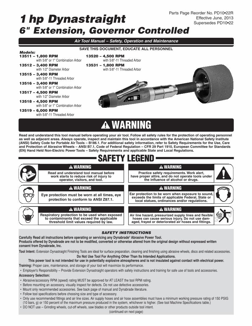
Air System
1 DROP/MIN.
20 SCFM
LUBRICATOR SETTING
• Dynabrade Air Power Tools are designed tooperate at 90 PSIG (6.2 Bar/620 kPa) maximumair pressure at the tool inlet, when the tool isrunning. Use recommended regulator to controlair pressure.
• Ideally the air supply should be free from moisture.Incorporating a refrigerated air dryer after thecompressor and drain valves at each tool station(as shown) further reduces moisture fromcondensation in the air supply.
➤➤
➤
➤
➤
➤

Disassembly Instructions - 1hp Extension DynastraightImportant: Manufacturer’s warranty is void if tool is disassembled before warranty expires.Disconnect tool from power source before tool repair.Motor Disassembly:
1. Remove abrasive accessory and hardware from arbor/threaded spindle.2. Using 51989 Repair Collar (order separately) or padded vise, secure front end of housing using machined flats on the silver ring.3. Remove 51952 Extension Handle from 53695 Gear Casing (twist counterclockwise).4. Slide 51982 Bearing Spacer and spindle assembly through rear of 51952 Extension Handle.5. Remove 96524 Retaining Ring from front of extension handle if necessary.6. Secure 51955 Spindle at wrench flats, and remove arbor/threaded spindle, 51956 Felt Ring and 51969 Coupling Nut.7. Secure 01007 Bearing and press 51955 Spindle through both 01007 Bearings.8. Secure 54520 Bearing and press 51955 through 54520 Bearing.9. Remove 53695 Gear Casing (twist counterclockwise).
10. Secure planetary Carrier using 53698 Wrench (order separately) and remove 51969 Coupling Nut (twist counterclockwise).11. Remove 04014 Set Screw(s) and pull planetary carrier assembly(s) from planetary gear casing.12. Press planetary carrier assembly through 54520 Bearing.13. Remove 96498 Wave Spring.14. Remove ring gear and press retainer pins and gears from planetary carrier.15. Remove remaining tool assembly from vise.16. Pull motor assembly from housing assembly.17. Remove governor assembly by using a slotted screw driver. (LEFT HAND thread)18. Secure 51925 Cylinder and place a 1/8" (3mm) drift pin to the base of the internal thread and press the 51921 Rotor from the 02057 Rear Bearing.19. Slide 02057 Rear Bearing from 51923 Rear Bearing Plate.20. Remove 51925 Cylinder and 51926 Blades.21. Press rotor through 54520 Bearing, 51922 Front Bearing Plate and 51927 Rotor Spacer.22. Slide 54520 Bearing and shims from 51922 Front Bearing Plate.Motor and Extension Disassembly Complete.
Housing Disassembly:1. Secure housing using 51989 Repair Collar (see back cover for Optional Accessories).2. Remove inlet bushing with muffler assembly (twist counterclockwise).3. Remove 53682 Gasket, 51943 Spring, 96442 O-Ring, 51940 Spacer, 94528 Felt Silencer, 53686 Muffler Cap, 94924 Wave Spring and
53683 Spacer from 53681 Inlet Bushing.4. Remove 51944 Tip Valve and 51945 Valve Seat.
Housing Disassembly Complete.
Assembly Instructions - 1hp Extension DynastraightMotor Assembly:Important: Be sure parts are clean and in good repair before assembling. Follow grease, oil and torque specifications.
1. Place Rotor into padded vise with male thread or spline facing upwards.2. Slip 51927 Rotor Spacer over rotor shaft and down against rotor body face.3. Press 96441 Coiled Pin into 51922 Front Bearing Plate. Make certain, coiled pin does not protrude beyond internal bearing surface.4. Place a .002" shim into the base of 51922 Front Bearing Plate as an initial spacing and slide 54520 Bearing to the front plate base. Note: 51951 Shim
Pack contains .001" and .002" shims.5. Press bearing/bearing plate assembly onto rotor. (For 1,800, 3,400, & 4,500 RPM Models) Slide bearing/bearing plate onto rotor and thread pinion
into place. Torque to 17 N•m (For 6,000 RPM Model.)6. Check clearance between rotor and front bearing plate by using a .001" feeler gauge. Clarence should be between .001" – .0015". Adjust clarence by
repeating steps 4 and 5 with different shims if necessary.7. Once proper rotor gap clarence is achieved, install well lubricated 51926 Blades (4) into rotor slots. Dynabrade recommends lubricating blades with
95842 Air Lube. Important: Make certain beveled edge of blade follows rotor outside diameter.8. Install 51925 Cylinder over rotor and front plate raised boss. Align coiled pin on front to cylinder slot.9. Press 96441 Coiled Pin into blind hole on 51923 Rear Bearing Plate. Press (2) 96445 Coiled Pins into the back side of rear bearing plate.
10. Peel backing off 51924 Gasket and align it firmly in place onto 51923 Rear Bearing Plate.11. Place 51923 Rear Bearing Plate over rotor mandrel and insert raised boss on rear bearing plate into cylinder diameter, while inserting short coiled pin
into cylinder slot. Be sure inlet slot on rear bearing plate line up with inlet slot on cylinder. Flip cylinder end to end and repeat step 8 for correct assembly.12. Press 02057 Bearing onto rotor and onto 51923 Rear Bearing Plate until it is seated. Important: Cylinder must fit snug between bearing plates. If too
tight, rotor will not turn freely. Rotor must be lightly tapped at press fit end until rotor spins freely while still maintaining a snug fit. A loose fit will notachieve the proper preload on motor bearing. While pressing 02057 Bearing, make certain to contact inner race of bearing only.
13. Add one drop of #243 Loctite® (or equiv.) to governor assembly male thread and screw governor assembly onto place (LEFT HAND thread) with aslotted screw head. Torque to 2 N•m (18 lb.-in.). (continued on next page)

Loctite® is a registered trademark of Loctite Corp.
Assembly Instructions - (Continued)Important: Manufacturer’s warranty is void if tool is disassembled before warranty expires.Please refer to parts breakdown for part identification.14. Install motor assembly into housing, making sure motor drops all the way into housing. Note: Align both 96445 Coiled Pins to slots in insert and
against 51924 Gasket.Motor Assembly Complete.
Gear Casing Assembly:1. Press Front 54520 Bearing onto front end of 53695 Gear Casing.2. Install gears with needle bearings and assemble onto planetary carrier by pressing retainer shafts into place.3. Place 96498 Wave Spring at the base of 53695 Gear Casing.4. Slide planetary carrier assembly into 53695 Gear Casing and through 54520 Bearing.5. Apply one drop of #243 Loctite® to threads of 51969 Coupling Nut and thread onto planetary carrier. Torque to 17 N•m (150 lb.-in.). Using 53698
Carrier Wrench (order separately).6. Install Ring Gear over 54520 Front Motor Bearing, keep 2 machined slots facing outward.7. After threaded surfaces have been properly cleaned and primed apply a small amount of #567 Loctite® to the male thread of the housing and
thread 53695 Gear Casing over ring gear in place. Important: Align rotor spline to planetary gears to allow carrier to spin freely.8. When slots from ring gear line up with set screw hole. Apply a small amount of #567 Loctite® to 04014 Set Screw and install to lock
ring gear in place.9. Torque 53695 Gear Casing to 35 N•m (310 lbs.-in.).
10. Place 50902 Coupler over 51969 Coupling Nut.11. Press one 01007 Bearing on end of 51955 Extension Spindle that is further from the wrench flats, then repeat with second 01007 Bearing on the same
end of the spindle. Important: While pressing 01007 Bearings, make certain to contact inner race of bearing only.12. Press 54520 Bearing onto end of spindle that is closer to wrench flats. Important: While pressing 54520 bearing, make certain to contact inner
race of bearing only.13. Secure 51955 Extension Spindle and apply #243 Loctite® (or equiv.) to external threads then torque 51969 Coupling Nut on single bearing end to
17 N•m (150 lbs.-in.).14. Install 51956 Felt Ring over small boss on the arbor/spindle selected.15. On double bearing end of 51955 Extension Spindle, apply #243 Loctite® (or equiv.) to external threads and torque arbor/spindle with 51956 Felt Ring to
17 N•m (150 lbs.-in.).16. Install 96524 Retaining Ring into groove inside 51952 Extension Handle.17. Insert spindle assembly, with arbor/spindle first, into larger diameter end of 51952 Extension Handle.18. Insert 51982 Bearing into larger diameter end of extension handle.19. Pull 50902 Coupler half way off of 51969 Coupling Nut, to insure proper alignment.20. Apply a small amount of #567 Loctite® (or equiv.) to external threads just above machined flats on 53695 Gear Casing.21. Align 50902 Coupler onto 51969 Coupling Nut in 51952 Extension Handle.22. Thread gear casing/housing assembly onto extension handle.23. Secure front end of housing using 51989 Repair Collar (order separately) or padded vase, align the vise jaws with machined flat on the silver ring.
Torque 51952 Extension Handle onto gear casing to 35 N•m (310 lbs.-in.).Gear Casing and Extension Assembly Complete.
Housing Assembly:1. Secure housing using 51989 Repair Collar (see back cover for Optional Accessories). With extension facing downward.2. Install 51945 Valve Seat by aligning 3 male prongs with three deep slots on insert. Make certain valve seat is pressed flat against
base of pocket. Note: Add a few drops of Dynabrade Air Lube (P/N 95842) to pocket walls before inserting 51945 Valve Seat.3. Install 51944 Tip Valve as shown.4. Slide 51942 Baffle into housing long end in first, and place 51941 Spring into shallow wall end of baffle.5. Pre-assemble muffler, slide 53683 Spacer over 53681 Inlet Bushing and up against the hex head base. Slide 94924 Wave Spring over 53681 Inlet
Bushing and up against spacer. Pre roll 94528 Felt Silencer and install it in 53686 Muffler Cap. Support felt/muffler cap assembly and slide 53681 InletBushing thru the inside until the muffler cap assembly seats against the 94924 Wave Spring. Flare the felt and place 51940 Spacer over male threadand set 96442 O-Ring into groove at the base of thread. Return felt to unflared form. Slide 51943 Spring into bushing and up to the two 51938 Screens.
6. Place 53682 Gasket over felt silencer and against 53686 Muffler Cap.7. Apply one drop of Loctite® #243 (or equiv.) to 51937 Inlet Bushing thread.8. Align small inside diameter of 51943 Spring to cone point on 51944 Tip Valve and thread 51937 Inlet Bushing and sub-assembly into place. Torque
bushing to 35 N•m (310 lb.-in.).9. Slide 96443 O-Ring onto 51946 Valve Stem and slide sub-assembly until o-ring passes through housing hole. Make certain valve stem assembly slides
freely after the o-ring passes through the hole.10. Remove housing from 51989 Repair Collar and replace repair collar onto the bench top with the part number identifier against the bench.
Align the throttle lever holes to housing pin hole and rest the housing and throttle lever onto the legs of the repair collar. Press 96444 Coiled Pin intolever hole and center into housing.
Tool Assembly Complete. Please allow 30 minutes for adhesives to cure before operating tool.Important: Before operating, place 2-3 drops of Dynabrade Air Lube (P/N 95842) directly into inlet with throttle lever depressed. Operate tool for 30 secondsto allow air lube to properly lubricate internal motor components. Motor should now be tested for proper operation at 90 PSIG max. If tool operates at a higherRPM than marked on the tool or if vibration and sound levels seem abnormal, the tool should be serviced to correct the cause before use.
Maintenance InstructionsImportant: A Preventative Maintenance Program is recommended whenever portable power tools are used.
• Use only genuine Dynabrade replacement parts to insure quality. To order replacement parts, specify Model#, Serial# and RPM of your air tool.• It is strongly recommended that all Dynabrade rotary vane air tools be used with a Filter-Regulator-Lubricator to minimize the possibility of misuse due
to unclean air, wet air or insufficient lubrication. Dynabrade recommends the following: 10681 Air Filter-Regulator-Lubricator (FRL) – Provides accurateair pressure regulation and two stage filtration of water contaminates.
• Dynabrade recommends one drop of air lube per minute for each 20 SCFM (example: if the tool specification states 40 SCFM, set the drip rate on the filter-lubricator to 2 drops per minute). Dynabrade Air Lube (P/N 95842: 1 pt 473 ml) is recommended.
• Grease the planetary gear assembly with 95542 Grease by applying 2-3 Plunges with 95541 Grease Gun every 50 of use, to achievemaximum gear life.
Routine Preventative Maintenance: Check free speed of Extension Dynastraight using a tachometer. This governor controlled grinder should be speed checkedevery 20 hours of use or weekly, whichever occurs more frequently.
• DO NOT disassemble the governor for any reason. Reorder correct speed – governor assembly (See Assembly Breakdown) and recheck free speed of toolwith a tachometer.
• Mineral spirits are recommended when cleaning the tool and parts. Do not clean tool or parts with any solvents or oils containing acids, esters, ketones,chlorinated hydrocarbons or nitro carbons.
• DO NOT clean or maintain tools with chemicals that have a low flash point (example: WD-40®).• A Motor Tune-Up Kit (P/N 96532) is available which includes high wear and medium wear motor parts.• Air tool labels must be kept legible at all times, if not, reorder label(s) and replace. User is responsible for maintaining specification information i.e.: Model #,
S/N, and RPM. (See Assembly Breakdown)• DO NOT carry tool by air hose or near the throttle lever.• Blow air supply hose out prior to initial use.• Visually inspect air hoses and fittings for frays, visible damage and signs of deterioration. Replace damaged or worn components.• Refer to Dynabrade's Warning/Safety Operating Instructions Tag (Reorder No. 95903) for safety information.
After maintenance is performed on tool, add a few drops of Dynabrade Air Lube (P/N 95842) to the air line and start the tool a few times to lubricate air motor. Checkfor excessive tool vibration.Handling and Storage:
• Use of tool rests, hangers and/or balancers is recommended.• Protect tool inlet from debris (see Notice below).• DO NOT carry tool by air hose or near the throttle lever.• Protect abrasive accessories from exposure to water, solvents, high humidity, freezing temperature and extreme temperature changes.• Store accessories in protective racks or compartments to prevent damage.
NoticeAll Dynabrade motors use the highest quality parts and metals available and are machined to exacting tolerances. The failure of quality pneumatic motors can most oftenbe traced to an unclean air supply or the lack of lubrication. Air pressure easily forces dirt or water contained in the air supply into motor bearings causing early failure.It often scores the cylinder walls and the rotor blades resulting in limited efficiency and power. Our warranty obligation is contingent upon proper use of our tools andcannot apply to equipment which has been subjected to misuse such as unclean air, wet air or a lack of lubrication during the use of this tool.
Machine SpecificationsModel Motor Motor Sound Air Flow Rate Air Pressure Wheel Arbor Weight Length Height
Number hp (W) RPM Level SCFM (LPM) PSIG (Bars) Diameter Inch Pound (kg) Inch (mm) Inch (mm)
13511 1 (745) 1,800 82 dB(A) 36 (1,019) 90 (6.2) 5/8 or 1 4.6 (2.0) 17-5/16 (440) 1-7/8 (48)
13512 1 (745) 3,400 80 dB(A) 41 (1,161) 90 (6.2) 1/2 4.4 (2.0) 18-5/8 (475) 1-7/8 (48)
13515 1 (745) 3,400 80 dB(A) 41 (1,161) 90 (6.2) 5/8-11 Thread 4.2 (1.8) 18-5/8 (475) 1-7/8 (48)
13516 1 (745) 3,400 80 dB(A) 41 (1,161) 90 (6.2) 5/8 or 1 4.7 (2.0) 18-5/8 (475) 1-7/8 (48)
13517 1 (745) 4,500 80 dB(A) 41 (1,161) 90 (6.2) 1/2 4.4 (1.9) 18-5/8 (475) 1-7/8 (48)
13518 1 (745) 4,500 80 dB(A) 41 (1,161) 90 (6.2) 5/8 or 1 4.7 (2.0) 18-5/8 (475) 1-7/8 (48)
13519 1 (745) 6,000 83 dB(A) 44 (1,256) 90 (6.2) 5/8-11 Thread 4.4 (2.0) 18-5/8 (475) 1-7/8 (48)
13520 1 (745) 4,500 80 dB(A) 41 (1,161) 90 (6.2) 5/8-11 Thread 4.4 (2.0) 18-5/8 (475) 1-7/8 (48)
13531 1 (745) 1,800 82 dB(A) 36 (1,019) 90 (6.2) 5/8-11 Thread 4.2 (1.8) 17-5/16 (440) 1-7/8 (48)
Additional Specifications: Air Inlet Thread 3/8" NPT • Hose I.D. Size 3/8" or 10mm • Air Flow Rate Based At Max HP. • Air Pressure 90 PSIG Max
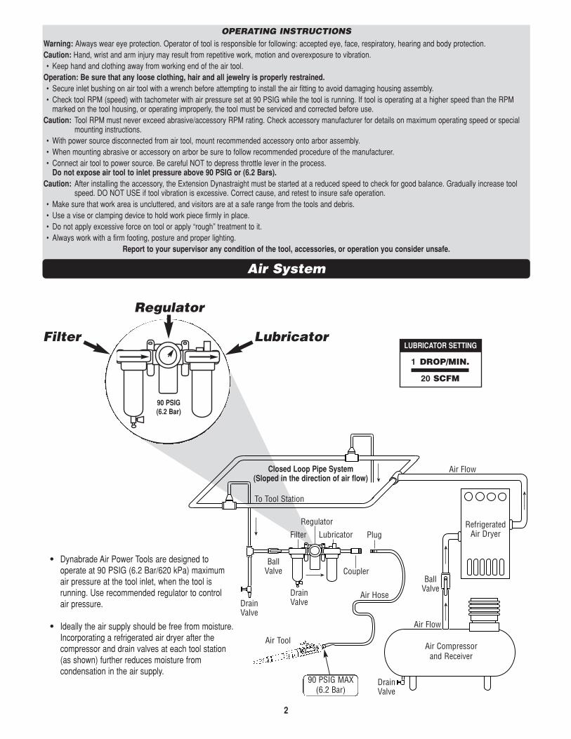
Extension Dynastraight® Arbors
1 95274 Hex Nut2 53626 5/8" – 11 Threaded Arbor3 95764 Screw4 13066 Front Flange 5/8"5 13065 Front Flange 1"
6 13063 Spacer (2)7 13062 Rear Flange8 13067 Spacer9 53628 Arbor 5/8" or 1" Diameter
10 95138 Hex Nut
11 13018 Spacer12 13021 Wheel Flange (2)13 53627 Arbor 1/2" Diameter
Index KeyNo. Part # Description
2 131112111098765431
5/8 - 11 Threaded Arbor 5/8" or 1" Combination Arbor 1/2" Diameter Arbor
For Models:13511, 13512, 1351513516, 13517, 1351813519, 13520, 13531
1 96524 Retaining Ring2 53690 Grip3 51952 Extension Handle4 Arbor (See Chart)5 51956 Felt Seal6 01007 Bearing (2)7 51955 Spindle Extension8 54520 Bearing (3)9 51982 Spacer
10 51969 Coupling Nut (2)11 50902 Coupler12 96498 Wave Spring (2)13 95438 O-Ring14 53620 Adapter15 01041 Grease Fitting16 04014 Set Screw17 53695 Adapter18 Carrier
53676 1,800 & 3,400 RPM53669 4,500 RPM53668 6,000 RPM
19 Planetary Gears53193 1,800 & 3,400 RPM53195 4,500 RPM53661 6,000 RPM
20 04026 Needle Bearing (4)96528 Bearing (3) 6,000 RPM Only
21 53679 Shaft (2) (Qty. 3 for 6,000 RPM)22 Ring Gear
53665 1,800, 3,400, 4,500 RPM53663 6,000 RPM
23 51951 Shim Pack (3/pkg.)24 51922 Front Bearing Plate25 96441 Pin (2)26 51927 Spacer27 51926 Blade (4/pkg.)28A 53660 Pinion (6,000 RPM Only)28 Rotor
53667 1,800 & 3,400 RPM53666 4,500 RPM53680 6,000 RPM
29 51925 Cylinder30 51923 Rear Bearing Plate31 02057 Bearing32 96445 Pin (2)33 51924 Gasket34 Governor Assembly
51953 1,800 RPM51933 3,400, 4,500, 6,000 RPM
35 All Housings Include:Warning & Specification Labels53711 Housing – Model 1351153712 Housing – Model 1351253715 Housing – Model 1351553716 Housing – Model 1351653717 Housing – Model 1351753718 Housing – Model 1351853719 Housing – Model 1351953796 Housing – Model 1352053794 Housing – Model 13531
36 96444 Pin37 51949 Safety Lock Lever38 51946 Valve Stem Assembly
(Incl. 96443 O-Ring)39 51945 Valve Seat40 51944 Tip Valve41 51943 Spring42* 96442 O-Ring43* 51940 Spacer44* 53682 Gasket45* 94528 Felt Silencer46* 53686 Muffler Cap47* 94924 Wave Spring48* 53683 Spacer49* 53681 Inlet Bushing
(Incl. 2 – 51938 Screens)50 01180 Warning Label51 01181 Specification Label
Index KeyNo. Part # Description
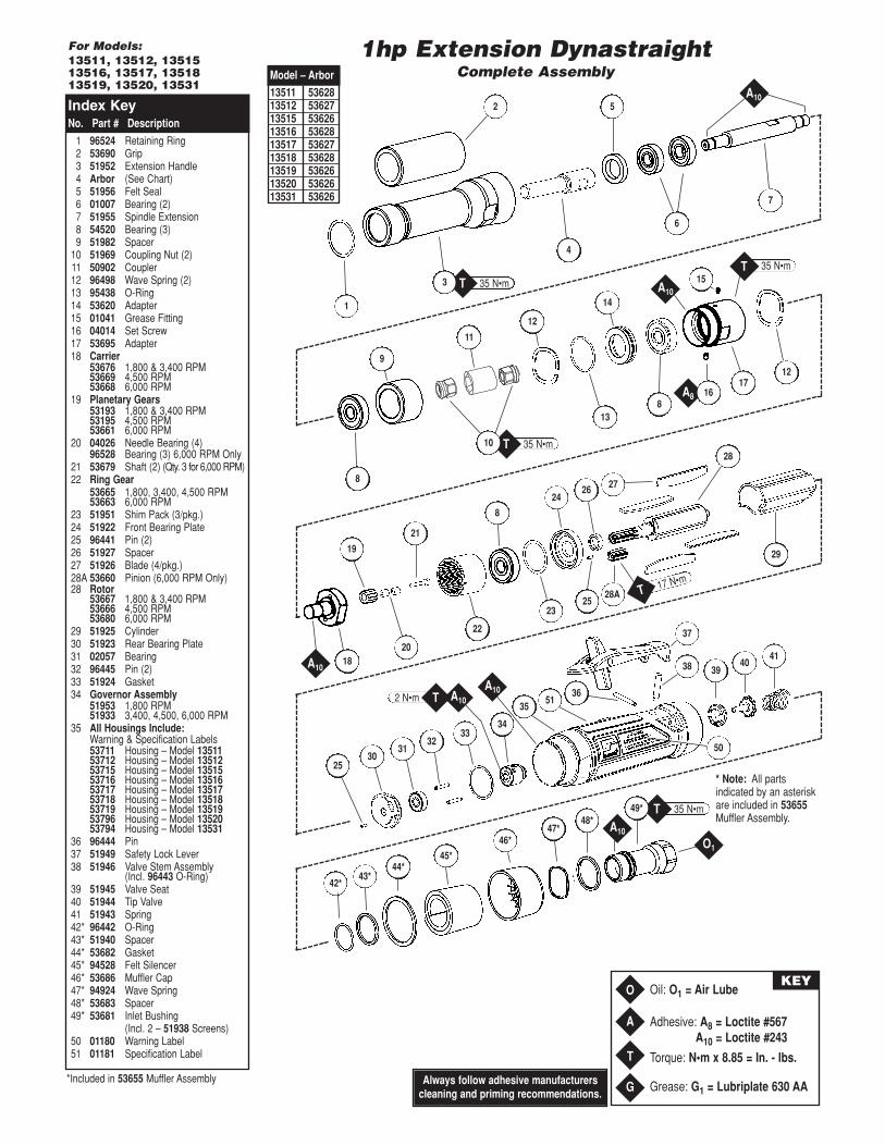
Adhesive: A8 = Loctite #567A10 = Loctite #243
Torque: N•m x 8.85 = In. - lbs.
Grease: G1 = Lubriplate 630 AA
Oil: O1 = Air LubeO
A
T
G
KEY
35 N•mT35 N•mT
1hp Extension DynastraightComplete Assembly
18
19
21
24
2523
8
26
28
27
29
22
1712
2530
3132
3334
5136
50
3940
4138
37
35
20
813
12
6
52
4
1
7
11
14
9
8
Model – Arbor
13511 5362813512 5362713515 5362613516 5362813517 5362713518 5362813519 5362613520 5362613531 53626
A10
A10
A8
2 N•m A10T
3 15
16
48*47*
46*
45*44*
43*42*
O1
35 N•mT
17 N•mT
49*
* Note: All partsindicated by an asteriskare included in 53655Muffler Assembly.
28A
Always follow adhesive manufacturerscleaning and priming recommendations.
A10
A10
A10
35 N•mT10
*Included in 53655 Muffler Assembly

This service chart is published as a guide to expectant life of component parts. The replacement levels are based on average toolusage over one year. Dynabrade Inc. considers one year usage to be 1,000 hours or 50% of a man year.
Preventative Maintenance ScheduleFor All 1hp Extension Dynastraights
LEGEND
T Included in Tune-Up Kit.
X Type of wear, no other comments apply.
L Easily lost. Care during assembly/disassembly.
D Easily damaged during assembly/disassembly.
R Replace each time tool is disassembled.
7
96532 – 1 Hp. Motor Tune-Up Kit
Note: Please refer to page 4 of tool manual for specific part number.
Parts Common to all Models:Index Part Description Number High Wear Medium Wear Low Wear Non-Wear
# Number Required 100% 70% 30% 10%1 96524 Retaining Ring 1 L2 53690 Grip 1 X3 51952 Extension Handle 1 X4 Arbor (See Chart) 1 X5 51956 Felt Seal 1 X6 01007 Bearing 2 X7 51955 Spindle Extension 1 X8 54520 Bearing 3 T9 51982 Spacer 1 X
10 51969 Coupling Nut 2 X11 50902 Coupler 1 X12 96498 Wave Spring 2 T, X13 95438 O-Ring 1 T14 53620 Adapter 1 X15 01041 Grease Fitting 1 X16 04014 Set Screw 1 L17 53695 Adapter 1 X18 See Note Carrier 1 X19 See Note Planetary Gears 1 X20 04026 Needle Bearing 4 X
96528 Bearing 3 X21 53679 Shaft See Note X22 See Note Ring Gear 1 X23 51951 Shim Pack (3/pkg.) 1 T24 51922 Front Bearing Plate 1 X25 96441 Pin 2 X26 51927 Spacer 1 T27 51926 Blade (4/pkg.) 1 X
28A 53660 Pinion 1 X28 See Note Rotor 1 X29 51925 Cylinder 1 X30 51923 Rear Bearing Plate 1 X31 02057 Bearing 1 T32 96445 Pin 2 X33 51924 Gasket 1 T34 See Note Governor Assembly 1 X35 See Note Housing 1 X36 96444 Pin 1 T37 51949 Safety Lock Lever 1 X38 51946 Valve Stem Assembly 1 T39 51945 Valve Seat 1 X40 51944 Tip Valve 1 T41 51943 Spring 1 X42 96442 O-Ring 1 T43 51940 Spacer 1 X44 53682 Gasket 1 X45 94528 Felt Silencer 1 T46 53686 Muffler Cap 1 X47 94924 Wave Spring 1 X48 53683 Spacer 1 X49 53681 Inlet Bushing (Incl. 51938 Screen (2) 1 X

DYNABRADE®
DYNABRADE, INC., 8989 Sheridan Drive • Clarence, NY 14031-1490 • Phone: (716) 631-0100 • Fax: 716-631-2073 • International Fax: 716-631-2524DYNABRADE EUROPE S.àr.l., Zone Artisanale • L-5485 Wormeldange—Haut, Luxembourg • Telephone: 352 76 84 94 1 • Fax: 352 76 84 95 1©DYNABRADE, INC., 2013 PRINTED IN USA
Visit Our Web Site: www.dynabrade.com Email: [email protected]
Optional AccessoriesDynaswivel®
• Swivels 360° AT TWO PIVOT POINTS allowing the air hose todrop directly to the floor while providing superb tool handling.95461 – 3/8" NPT.
51989 Repair Collar• Specially designed collar for use in vise to prevent damage
to valve body of tool during disassembly/assembly.
94465 Wheel inflation Tool• Controlled inflation/deflation of
pneumatic wheel.• Has 1/4" female thread; fits 1/4" air hose.• 95633 Nozzle replacement available.
Dynabrade Air Lube• Formulated for pneumatic equipment.• Absorbs up to 10% of its weight in water.• Prevents rust and formation of sludge.• Keeps pneumatic tools operating longer
with greater power and less down time.95842: 1pt. (473 ml)95843: 1gal. (3.8 L)
94472 Pneumatic Wheel• Easily regulate hardness by air pressure.• Inflates to 20 PSI maximum.
95542 Grease 10 oz. • Multi-purpose grease for all types of bearings, cams, gears.• High film strength; excellent resistance to water, steam, etc.• Workable range 0˚ F to 300˚ F.
95541 Push-type Grease Gun• One-hand operation.
96005 Male Plug• Provides up to twice the air flow
compared to standard plug design.• Plug has “ported” design to prevent
“starving” of the air tool.
95281 – 19mm Open-end Wrench.
96532 Motor Tune-Up Kit • Includes assorted parts to help maintain
and repair motor.Drop-In Motor • Allows quick and easy replacement.
No motor adjustments needed.01903 – 6,000 RPM01904 – 4,500 RPM01905 – 1,800 & 3,400 RPM
53698 Carrier Wrench• Carrier Wrench has a 3/8 in. square
socket for use with 3/8 in. drive; breaker bar, ratchet head, or torque wrenches.
53699 Carrier Wrench• 3 Sided wrench to for use with
6,000 RPM models.
53199 Handle Mount53163 Handle Assembly• Improved ergonomic feel with grip-traction to
reduce hand fatigue.
Bearing Press Tools• Used to install bearings.
96243: For installing 02057 Bearing.96244: For installing 01007 & 54520 Bearings.
Reference Contact Information1. American National Standards
Institute – ANSI25 West 43rd StreetForth FloorNew York, NY 10036Tel: 1 (212) 642-4900Fax: 1 (212) 398-0023
3. Power Tool Institute, Inc.P.O. Box 818Yachata, Oregon 97498-0818Tel: 1 (503) 547-3185Fax: 1 (503) 547-3539
4. European Committee for StandardizationRue de Stassart 36B - 1050 Brussels, Belgium
2. Government Printing Office – GPOSuperintendent of DocumentsAttn. New OrdersP.O. Box 371954Pittsburgh, PA 15250-7954Tel: 1 (202) 512-1803
Lifetime WarrantyAll Dynabrade portable pneumatic power tools are rigorously inspected and performance tested in our factory before shipping to our customers. If a Dynabrade tool developsa performance problem and an inherent defect is found during normal use and service, Dynabrade will warrant this tool against defects in workmanship and materials forthe lifetime of the tool. Upon examination and review at our factory, Dynabrade shall confirm that the tool qualifies for warranty status, and will repair or replace the tool atno charge to the customer. Normally wearable parts and products are NOT covered under this warranty. Uncovered items include bearings, contact wheels, rotor blades,regulators, valve stems, levers, shrouds, guards, O-rings, seals, gaskets and other wearable parts. Dynabrade’s warranty policy is contingent upon proper use of our toolsin accordance with factory recommendations, instructions and safety practices. It shall not apply to equipment that has been subjected to misuse, negligence, accident ortampering in any way so as to affect its normal performance. To activate lifetime warranty, customer must register each tool at www.dynabrade.com. Dynabrade will nothonor lifetime warranty on unregistered tools. A one-year warranty will be honored on all unregistered portable pneumatic power tools. Lifetime warranty applies only toportable pneumatic tools manufactured by Dynabrade, Inc. in the USA. Lifetime warranty applies only to the original tool owner; warranty is non-transferable.


![Vegl feltetelek EJBFN23 A 20180924...ð /hmiudw ho wwl ylvv]dyiowivl |vv]hj pv giwxp 1hp dondopd]dqgy 5pv]ehq il]hwhww mho]iorjohyhohnuh yrqdwnr]y uhqghonh]pvhn 1hp dondopd]dqgy](https://img.pdfslide.net/doc/110x75/5ea40eb2de5c525f77037760/vegl-feltetelek-ejbfn23-a-20180924-hmiudw-ho-wwl-ylvvdyiowivl-vvhj-pv.jpg)