Embed Size (px)
Citation preview
1MW 4160Volt Diesel Generators
Emergency Power Solutions
Turbine Marine Inc.
1940 NW 32nd Street
Pompano Beach, FL 33064
Tel: 954-979-4409
Fax: 954-984-8110
www.turbinemarine.com

2 | P a g e
AIR-LIFT TRANSPORT SOLUTION
(May also be transported by pick-up truck, flatbed truck or air-freight)
EQUIPMENT DESCRIPTION:
Turbine Marine 1MW 4160Volts 60HZ 3 Phase Compact Series Turbine-Powered Generator
GENERAL DESCRIPTION:
The Compact Series turbine-powered generator is so innovative and lightweight it can be easily towed
with a standard size pick-up truck, or airlifted by helicopter as its weight is only approximately 9000 lbs
and its overall dimensions are 144” L x 84” W x 86” H (12’ L x 7’ W x 7.16’ H).
Its enclosure is sleek and aerodynamic to reduce drag while in tow or flight. The Military Lycoming T-53,
engine powers the Compact series generator. It has the capability of using multiple fuels, including but
not limited to: jet, diesel, gasoline and bio-fuels, without any changes to the unit by the user.
The Compact Series is manufactured with the highest industry standard components, such as Marathon
Electric Generators (alternators) and Woodward Electrical controls for engine management and
electrical current monitoring. The unit has a full digital control panel that is also capable of synchronizing
multiple generator units. The 1MW generator assemblies can be ordered in any Hz and voltage
configurations that the application may demand. The high-tech carbon fiber composite, fully
weatherproofed enclosure houses a self-monitoring safety and shut down system. The enclosure also
incorporates a dust/saltwater mist air filtration system for both the generator and alternator. This
filtration system allows proper operation in any conditions land or sea. The generator assembly can be
trailer-mounted for easy mobility. The trailer is a quick-mount system that can be removed in minutes
and, by the use of the built-in air lift apparatus, the generator can be lifted by a medium size helicopter.
All of our generators are easily serviced throughout the world.
3 | P a g e
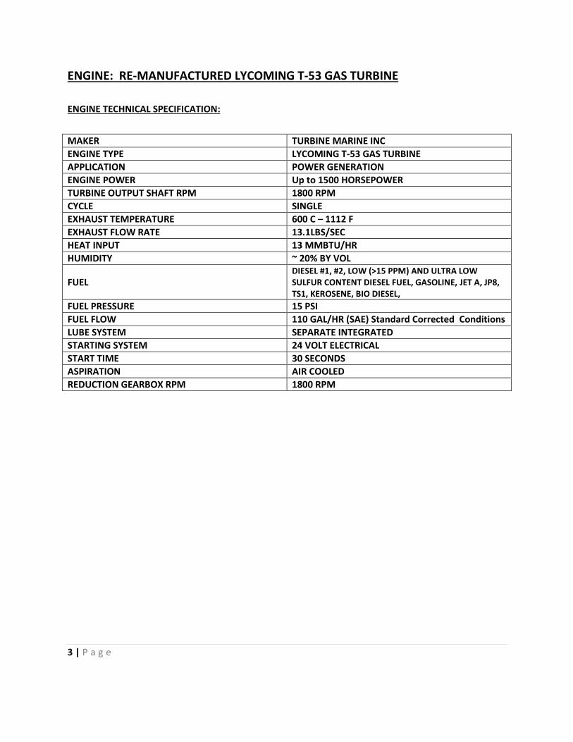
ENGINE: RE-MANUFACTURED LYCOMING T-53 GAS TURBINE
ENGINE TECHNICAL SPECIFICATION:
MAKER TURBINE MARINE INC
ENGINE TYPE LYCOMING T-53 GAS TURBINE
APPLICATION POWER GENERATION
ENGINE POWER Up to 1500 HORSEPOWER
TURBINE OUTPUT SHAFT RPM 1800 RPM
CYCLE SINGLE
EXHAUST TEMPERATURE 600 C – 1112 F
EXHAUST FLOW RATE 13.1LBS/SEC
HEAT INPUT 13 MMBTU/HR
HUMIDITY ~ 20% BY VOL
FUEL DIESEL #1, #2, LOW (>15 PPM) AND ULTRA LOW SULFUR CONTENT DIESEL FUEL, GASOLINE, JET A, JP8, TS1, KEROSENE, BIO DIESEL,
FUEL PRESSURE 15 PSI
FUEL FLOW 110 GAL/HR (SAE) Standard Corrected Conditions
LUBE SYSTEM SEPARATE INTEGRATED
STARTING SYSTEM 24 VOLT ELECTRICAL
START TIME 30 SECONDS
ASPIRATION AIR COOLED
REDUCTION GEARBOX RPM 1800 RPM
4 | P a g e
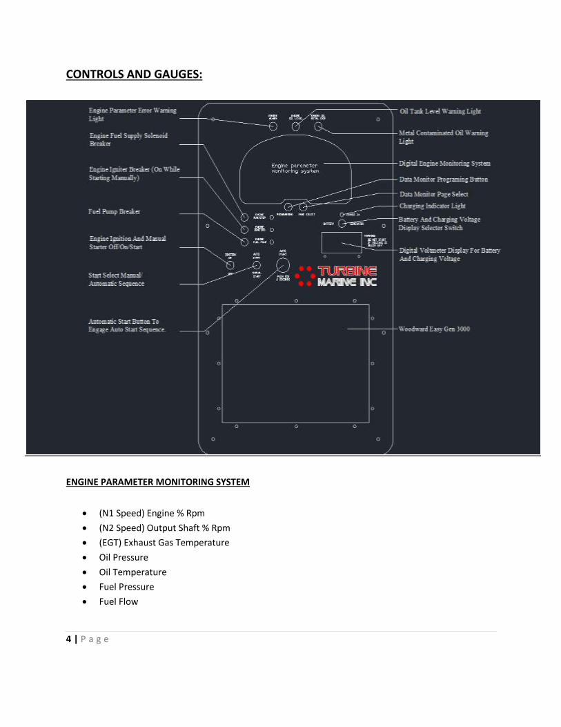
CONTROLS AND GAUGES:
ENGINE PARAMETER MONITORING SYSTEM
(N1 Speed) Engine % Rpm
(N2 Speed) Output Shaft % Rpm
(EGT) Exhaust Gas Temperature
Oil Pressure
Oil Temperature
Fuel Pressure
Fuel Flow
5 | P a g e
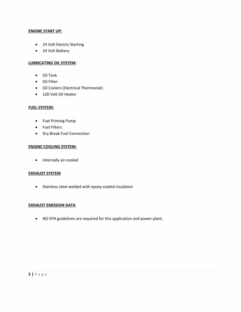
ENGINE START UP:
24 Volt Electric Starting
24 Volt Battery
LUBRICATING OIL SYSTEM:
Oil Tank
Oil Filter
Oil Coolers (Electrical Thermostat)
120 Volt Oil Heater
FUEL SYSTEM:
Fuel Priming Pump
Fuel Filters
Dry Break Fuel Connection
ENGINE COOLING SYSTEM:
Internally air-cooled
EXHAUST SYSTEM
Stainless steel welded with epoxy coated insulation
EXHAUST EMISSION DATA
NO EPA guidelines are required for this application and power plant.
6 | P a g e
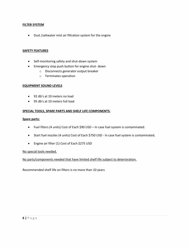
FILTER SYSTEM
Dust /saltwater mist air filtration system for the engine
SAFETY FEATURES
Self-monitoring safety and shut-down system
Emergency stop push button for engine shut- down
o Disconnects generator output breaker
o Terminates operation
EQUIPMENT SOUND LEVELS
92 db’s at 10 meters no load
95 db’s at 10 meters full load
SPECIAL TOOLS, SPARE PARTS AND SHELF LIFE COMPONENTS:
Spare parts:
Fuel filters (4 units) Cost of Each $90 USD – In case fuel system is contaminated.
Start fuel nozzles (4 units) Cost of Each $750 USD - In case fuel system is contaminated.
Engine air filter (1) Cost of Each $275 USD
No special tools needed.
No parts/components needed that have limited shelf life subject to deterioration.
Recommended shelf life on filters is no more than 10 years
7 | P a g e
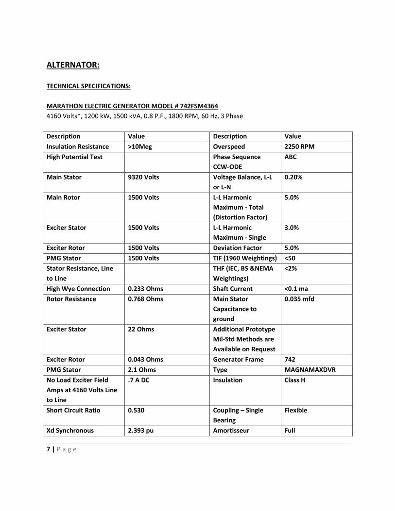
ALTERNATOR:
TECHNICAL SPECIFICATIONS:
MARATHON ELECTRIC GENERATOR MODEL # 742FSM4364
4160 Volts*, 1200 kW, 1500 kVA, 0.8 P.F., 1800 RPM, 60 Hz, 3 Phase
Description Value Description Value
Insulation Resistance >10Meg Overspeed 2250 RPM
High Potential Test Phase Sequence
CCW-ODE
ABC
Main Stator 9320 Volts Voltage Balance, L-L
or L-N
0.20%
Main Rotor 1500 Volts L-L Harmonic
Maximum - Total
(Distortion Factor)
5.0%
Exciter Stator 1500 Volts L-L Harmonic
Maximum - Single
3.0%
Exciter Rotor 1500 Volts Deviation Factor 5.0%
PMG Stator 1500 Volts TIF (1960 Weightings) <50
Stator Resistance, Line
to Line
THF (IEC, BS &NEMA
Weightings)
<2%
High Wye Connection 0.233 Ohms Shaft Current <0.1 ma
Rotor Resistance 0.768 Ohms Main Stator
Capacitance to
ground
0.035 mfd
Exciter Stator 22 Ohms Additional Prototype
Mil-Std Methods are
Available on Request
Exciter Rotor 0.043 Ohms Generator Frame 742
PMG Stator 2.1 Ohms Type MAGNAMAXDVR
No Load Exciter Field
Amps at 4160 Volts Line
to Line
.7 A DC Insulation Class H
Short Circuit Ratio 0.530 Coupling – Single
Bearing
Flexible
Xd Synchronous 2.393 pu Amortisseur Full
8 | P a g e
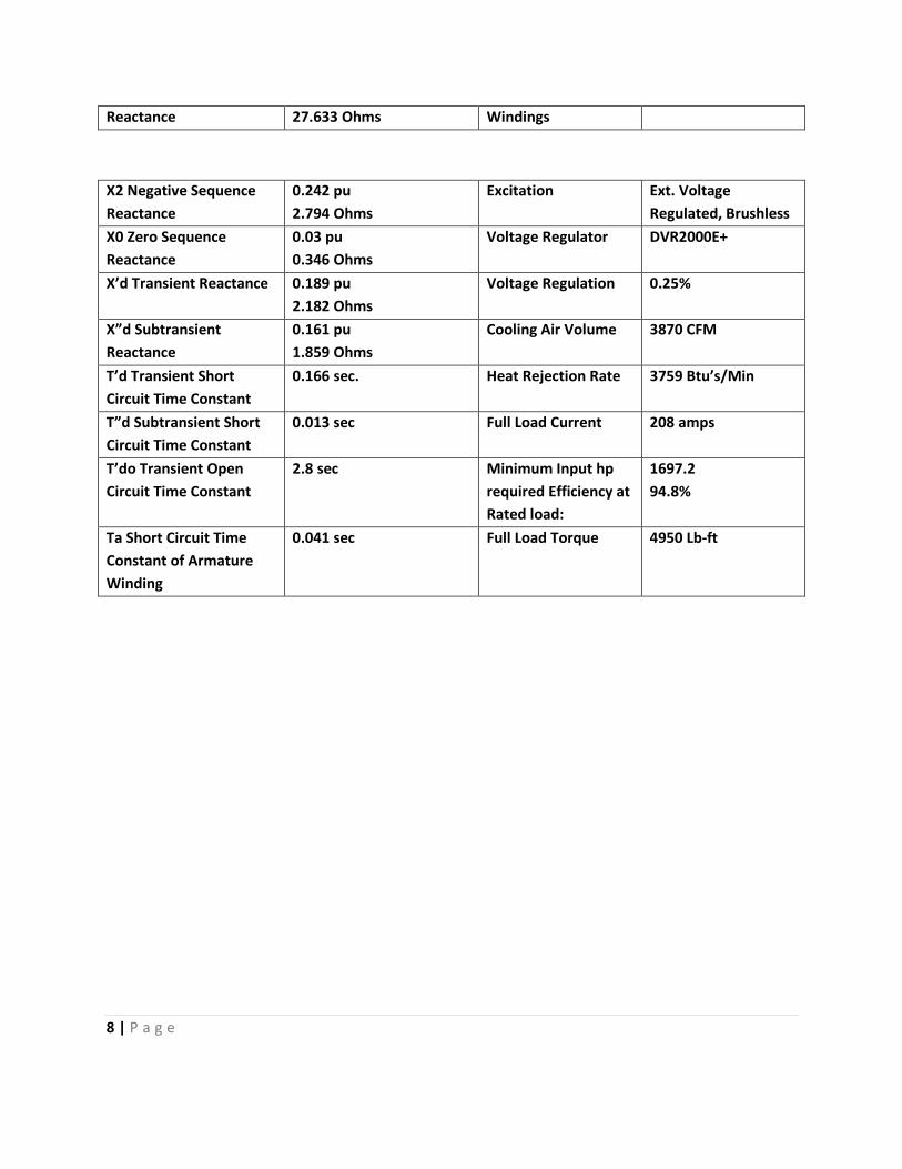
Reactance 27.633 Ohms Windings
X2 Negative Sequence
Reactance
0.242 pu
2.794 Ohms
Excitation Ext. Voltage
Regulated, Brushless
X0 Zero Sequence
Reactance
0.03 pu
0.346 Ohms
Voltage Regulator DVR2000E+
X’d Transient Reactance 0.189 pu
2.182 Ohms
Voltage Regulation 0.25%
X”d Subtransient
Reactance
0.161 pu
1.859 Ohms
Cooling Air Volume 3870 CFM
T’d Transient Short
Circuit Time Constant
0.166 sec. Heat Rejection Rate 3759 Btu’s/Min
T”d Subtransient Short
Circuit Time Constant
0.013 sec Full Load Current 208 amps
T’do Transient Open
Circuit Time Constant
2.8 sec Minimum Input hp
required Efficiency at
Rated load:
1697.2
94.8%
Ta Short Circuit Time
Constant of Armature
Winding
0.041 sec Full Load Torque 4950 Lb-ft
9 | P a g e
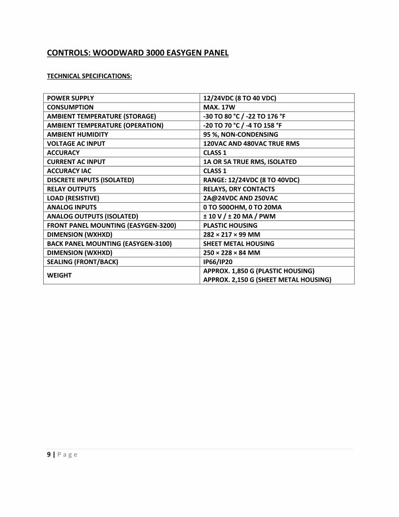
CONTROLS: WOODWARD 3000 EASYGEN PANEL
TECHNICAL SPECIFICATIONS:
POWER SUPPLY 12/24VDC (8 TO 40 VDC)
CONSUMPTION MAX. 17W
AMBIENT TEMPERATURE (STORAGE) -30 TO 80 °C / -22 TO 176 °F
AMBIENT TEMPERATURE (OPERATION) -20 TO 70 °C / -4 TO 158 °F
AMBIENT HUMIDITY 95 %, NON-CONDENSING
VOLTAGE AC INPUT 120VAC AND 480VAC TRUE RMS
ACCURACY CLASS 1
CURRENT AC INPUT 1A OR 5A TRUE RMS, ISOLATED
ACCURACY IAC CLASS 1
DISCRETE INPUTS (ISOLATED) RANGE: 12/24VDC (8 TO 40VDC)
RELAY OUTPUTS RELAYS, DRY CONTACTS
LOAD (RESISTIVE) 2A@24VDC AND 250VAC
ANALOG INPUTS 0 TO 500OHM, 0 TO 20MA
ANALOG OUTPUTS (ISOLATED) ± 10 V / ± 20 MA / PWM
FRONT PANEL MOUNTING (EASYGEN-3200) PLASTIC HOUSING
DIMENSION (WXHXD) 282 × 217 × 99 MM
BACK PANEL MOUNTING (EASYGEN-3100) SHEET METAL HOUSING
DIMENSION (WXHXD) 250 × 228 × 84 MM
SEALING (FRONT/BACK) IP66/IP20
WEIGHT APPROX. 1,850 G (PLASTIC HOUSING) APPROX. 2,150 G (SHEET METAL HOUSING)
10 | P a g e
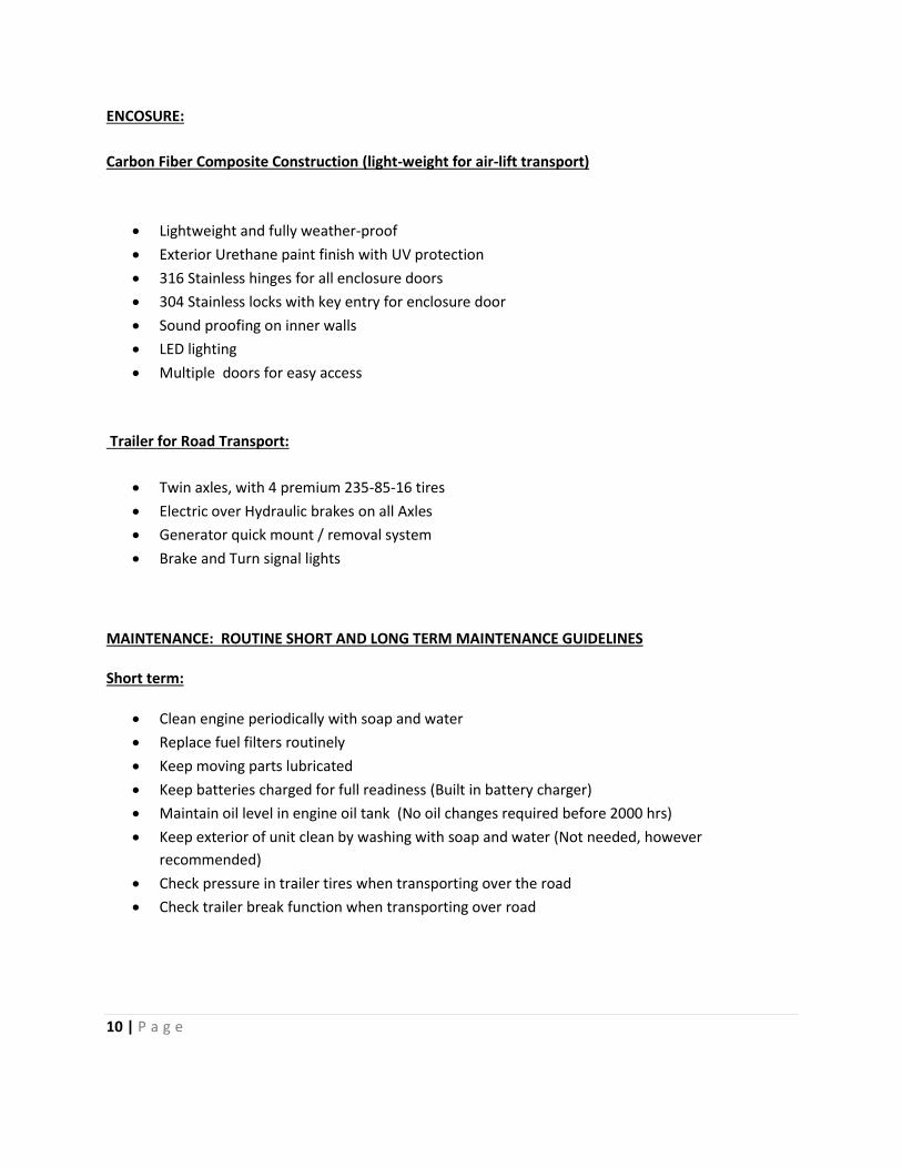
ENCOSURE:
Carbon Fiber Composite Construction (light-weight for air-lift transport)
Lightweight and fully weather-proof
Exterior Urethane paint finish with UV protection
316 Stainless hinges for all enclosure doors
304 Stainless locks with key entry for enclosure door
Sound proofing on inner walls
LED lighting
Multiple doors for easy access
Trailer for Road Transport:
Twin axles, with 4 premium 235-85-16 tires
Electric over Hydraulic brakes on all Axles
Generator quick mount / removal system
Brake and Turn signal lights
MAINTENANCE: ROUTINE SHORT AND LONG TERM MAINTENANCE GUIDELINES Short term:
Clean engine periodically with soap and water
Replace fuel filters routinely
Keep moving parts lubricated
Keep batteries charged for full readiness (Built in battery charger)
Maintain oil level in engine oil tank (No oil changes required before 2000 hrs)
Keep exterior of unit clean by washing with soap and water (Not needed, however
recommended)
Check pressure in trailer tires when transporting over the road
Check trailer break function when transporting over road
11 | P a g e
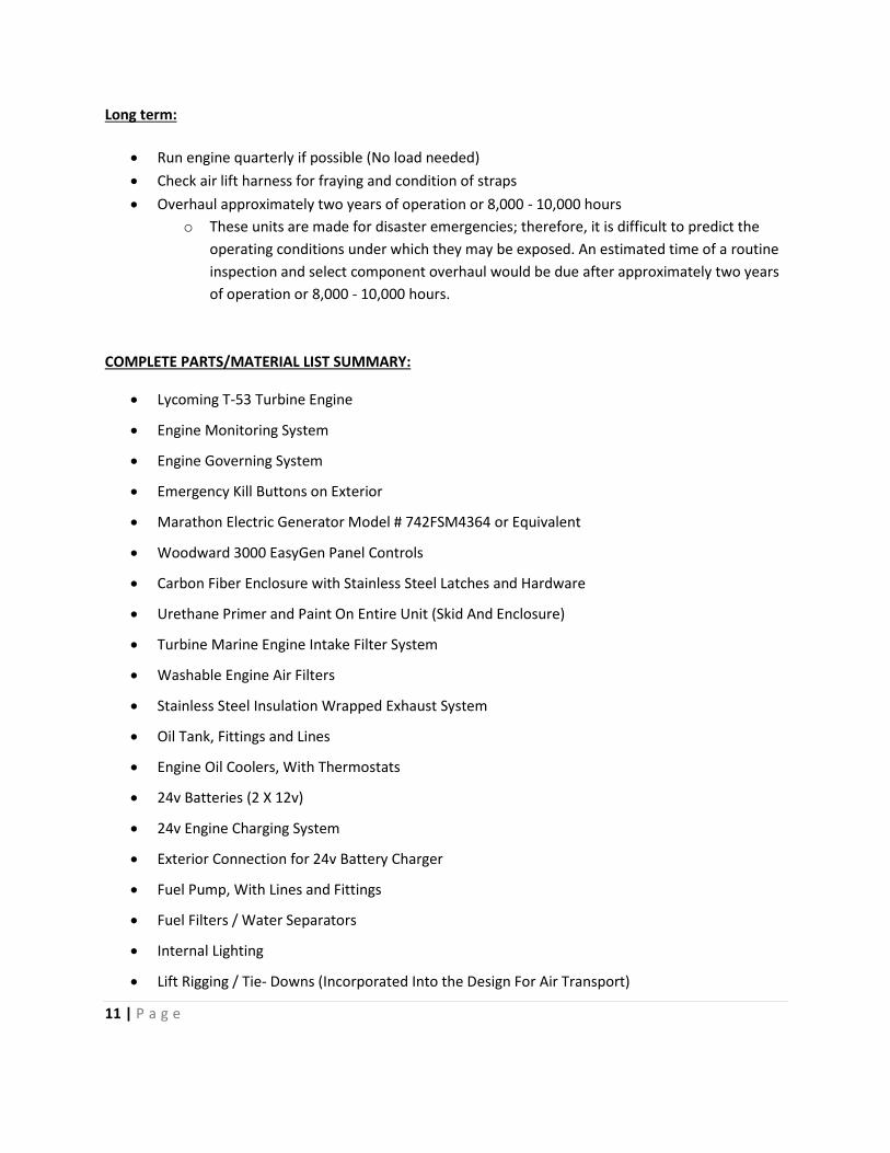
Long term:
Run engine quarterly if possible (No load needed)
Check air lift harness for fraying and condition of straps
Overhaul approximately two years of operation or 8,000 - 10,000 hours
o These units are made for disaster emergencies; therefore, it is difficult to predict the
operating conditions under which they may be exposed. An estimated time of a routine
inspection and select component overhaul would be due after approximately two years
of operation or 8,000 - 10,000 hours.
COMPLETE PARTS/MATERIAL LIST SUMMARY:
Lycoming T-53 Turbine Engine
Engine Monitoring System
Engine Governing System
Emergency Kill Buttons on Exterior
Marathon Electric Generator Model # 742FSM4364 or Equivalent
Woodward 3000 EasyGen Panel Controls
Carbon Fiber Enclosure with Stainless Steel Latches and Hardware
Urethane Primer and Paint On Entire Unit (Skid And Enclosure)
Turbine Marine Engine Intake Filter System
Washable Engine Air Filters
Stainless Steel Insulation Wrapped Exhaust System
Oil Tank, Fittings and Lines
Engine Oil Coolers, With Thermostats
24v Batteries (2 X 12v)
24v Engine Charging System
Exterior Connection for 24v Battery Charger
Fuel Pump, With Lines and Fittings
Fuel Filters / Water Separators
Internal Lighting
Lift Rigging / Tie- Downs (Incorporated Into the Design For Air Transport)
12 | P a g e
Easy Mount Lift off Release Trailer
Trailer Hitch and Lights (For Towing By Truck)
Trailer Tires (4)
WARRANTY
1 year from date of delivery.
PRICING
Upon request
TERMS OF PAYMENT:
Upon request
Delivery Schedule:
Subject to quantity
SHIPPING:
Per unit shipping weight(s) in pounds: approximately 9000 lbs
Unit dimensions in inches: 144” L x 84” W x 86” H (12’ L x 7’ W x 7.16’ H).
DESIGN DESCRIPTION
4160 VAC Trailer or Skid mounted generator
Our generators are mounted on a quick-mount system trailer for over road transport. However, trailer is
designed for an easy removal for air-lift transport. They are also equipped with hooks and hardware that
allows them to be lifted by a medium size helicopter.
Our equipment has the potential to be utilized in various utilities across the United States. Using our
own design, geared to emergency operations such as those that may be experienced by the Purchaser,
our generators are specifically designed for the emergency, standby requirements of this bid.
13 | P a g e
General
Our equipment is non-safety-related (commercial grade).
Our equipment is made with common materials and components.
Our equipment can be lifted by a forklift and is designed to be lifted by a medium sized helicopter
and/or sent by air-freight. Our units have the following dimensions, 144” Length, 84” width, and 86”
height.
Separation of support equipment is required, such as fuel tanks and circuit breaker assembly will be
designed to have air-lift capabilities.
The units have preinstalled lifting points and connections to be transported by helicopter.
The T-53 turbine engines can operate on DIESEL #1, #2, Low (>15 ppm) and ultra low Sulfur content
Diesel fuel.
Controls and gauges include Start/Run/Stop switch, Voltage Meter, Oil Pressure, Tachometer, Engine air
temperature, Fuel gauge.
Diesel fuel tanks can be provided separately. The unit was designed WITHOUT fuel tanks to meet weight
requirements for air transport with medium duty helicopter.
Turbine Marine Compact series generator units can be operated at any power level for any period of
time. Power output from 50Kw at engine idle up to 1MW at full load. The turbine engine system is
designed to throttle back to minimize fuel consumption at lower levels of load.
The generator will have a steady state output voltage rating of 480 VAC. It will meet the Voltage
regulation no load to full load to plus or minus 0.5 percent voltage regulation.
The generator will be a three phase 60 Hz synchronous machine. Steady State frequency variation will
be within plus or minus 0.25 percent.
The generator will have the capability to auto synchronize and operate in parallel with a similar rated
machine for extended duration. The engine and generator set will have all necessary hardware to
parallel multiple machines with any interface requirements supplied by Turbine Marine Inc.
14 | P a g e
The engine and the generator will be able to withstand full load rejection without tripping or over
speeding.
The generator will have neutral ground and two safety ground capability. The Safety ground will be
capable of connecting to station grounding grid for proper equipment operation and personal safety.
The engine and the generator will have its instrument rack and the control panel with all the controls
including the emergency stop button and alarms.
The generator will trip and alarm on under-voltage, over-current, and reverse power conditions. The
required power to operate the protective devices will be integrated into the generator assembly. No site
power will be needed to operate the protective devices.
For an over-speed, short-circuit conditions, the generator will have an automatic shutdown and alarm.
Circuit breakers for conductor protection can be provided separately!
Environmental requirements
The engine, generator and support equipment will be capable of continuous duty rated output at an
ambient temperature between -40 F and 130 F.
The engine and generator will be capable of starting and developing required output characteristics
without external support for starting in these environmental conditions, following a transportation
period of up to 16 hours (i.e., no external power supplied to auxiliaries, such as heaters or battery
chargers).
The engine, generator and support equipment will meet the description as described in NEI 12-06,
“Portable towable equipment that is designed for over the road transport typically used in
construction/remote sites are deemed sufficiently rugged to function following a BDB seismic event.”
15 | P a g e
Principles and Methods of Operation:
Principle: A Turbine Marine prepared turbo shaft turbine aviation engine is directly coupled to an
industrial 1 MW alternator. A Woodward (off the shelf Diesel engine unit) electronic governing system is
connected to the turbine engine’s liquid fuel control system that maintains 60Hz as it adds or removes
fuel from the engine. This is possible as the electronic governing system senses RPM from the on-board
sensors.
Method of Operation for 1MW (Continuous Operation) Generator Air- Lift Transport:
Airlift Transport:
1. Lower generator unit on as flat as possible surface.
2. Lower fuel bladder as close to generator unit as possible.
3. Lower Generator’s main breaker and cable assemblies as close to unit as possible.
Electrical Connections:
4. Connect all cables from generator to generator main breaker. Breaker control cable / Line
Phase 1 / Line phase 2 / line phase 3 / Neutral / Ground. (All Cables and connections will have
standard color coding)
5. Connect load to generator main breaker (Confirm phase rotation to color codes on generator
main breaker)
Fuel:
6. Connect fuel source to generator unit and open fuel vent valve on tank. (Quick disconnect Dry
break fuel coupling and hose supplied with fuel bladders assembly)
Generator Operation and Automatic Start Sequence:
7. Secure or remove 4 point generator lifting harness used for air transport from generator unit.
(Must not obstruct exhaust or air intake on generator unit).
8. Remove generator engine air intake cover
9. Turn main start battery switch on.
10. Turn on generator ignition switch and position start selector switch to Auto.
11. Turn on fuel priming pump.
12. Push start button for 2 seconds and release. (Auto start function has initiated)
13. Unit will spool up for 30 seconds and start. Generator unit is now stabilized at 60 Hz and is
ready for operation.
14. After unit is in operation.
* check oil level indicator sight Glass on oil tank. If oil level indicates low, top off oil level using
on board oil supply tank.
16 | P a g e
(Open oil supply tank level valve until oil is at full mark on oil tank indicator, then close valve).
15. Any abnormal engine or alternator operating parameters will now be visible on the dash panel
warning light system if triggered.
Generator Parallel Operation Procedure for Turbine Marine 1MW Compact Series Generators
Airlift Transport:
1. Lower main Circuit breaker with busbar on a flat as possible surface
Electrical connections:
2. Connect emergency load to main circuit breaker. Breaker control cable / Line Phase 1 / Line
phase 2 / Line phase 3 / Neutral / Ground. (All Cables and connections will have standard color
coding)
3. Connect all generator main breakers that will be run in parallel to emergency load main breaker.
Breaker control cable / Line Phase 1 / Line phase 2 / Line phase 3 / Neutral / Ground. (All Cables
and connections will have standard color coding)
4. Connect circuit breaker control and load sensing cables to generator circuit breakers and main
emergency load circuit breaker.
5. Connect CAN bus cable between generator control panels that will be run in parallel.
6. Start all generators that will be run in parallel per operating instructions (generator operation
and automatic start sequence).
7. Generators will engage generator circuit breakers and synchronize before engaging main circuit
breaker connecting to load.
8. Woodward Easy-gen system will sense load and shut down generator (s) not needed to carry
load to save fuel. The delay time for adding another generator on line to maintain load is
customer programmable.
17 | P a g e
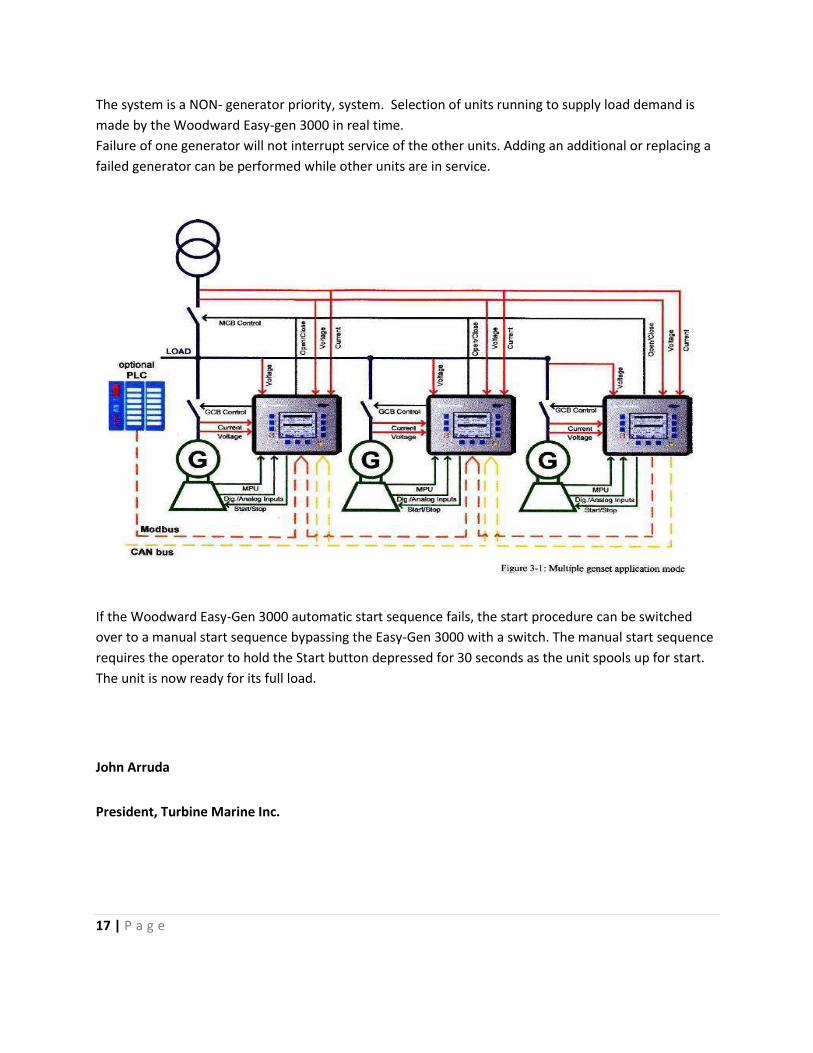
The system is a NON- generator priority, system. Selection of units running to supply load demand is
made by the Woodward Easy-gen 3000 in real time.
Failure of one generator will not interrupt service of the other units. Adding an additional or replacing a
failed generator can be performed while other units are in service.
If the Woodward Easy-Gen 3000 automatic start sequence fails, the start procedure can be switched
over to a manual start sequence bypassing the Easy-Gen 3000 with a switch. The manual start sequence
requires the operator to hold the Start button depressed for 30 seconds as the unit spools up for start.
The unit is now ready for its full load.
John Arruda
President, Turbine Marine Inc.