Embed Size (px)
Citation preview

P.Oa 1 01 L '. EDT 6 3 0 4 9 7 ENGINEERING DATA TRANSMITTAL
iA1 IC1 (DI Sheet Re". Item (81 DocumsntlDrawing No.
NO. NO. NO.
1 RPP-7266 N/A 0
2. To: (Receiving Organization) D i s t r i b u t i o n
iEl Title or Description of Data Transmitted
Tank 241-AP-104 Grab Sampling and Analysis Plan
~ ~~
5. Proj.lProg.lOept.1Div.:
R iver Pro tec t ion Project/Tank 241 -AP- 104/DD&IlDouble Shel l Tank- Waste Feed De l ivery 8. o r i g ina to r Remarks:
Approval Designator (FI Reason far Transmittal [GI
1. Approval 4. Review
3. Information
E. S. (1, 0 or NIA (see WHC-CM-3-5, 2. Release 5. Post-Review Ssc.12.7) 6 . Dist. (Receipt Acknow. Required1
3. From: (Or ig inat ing Organization)
D a t a Development and I n t e r p r e t a t i o n
6. Design Author i ty1 Design AgentlCog.
Disposition iH1 & (11 1. Approved 4. Reviewed nolcornmenr 2. Approved wlcomment 5. Reviewed Wlcornment 3 . Disapproved wlcomrnent 6. Receipt acknowledged
Engr.: Andrew M . Templeton
This t document i s being released i n t o t h e support ing document system f o r r e t r i e v a b i l i t y purposes.
For re lease. 11. Receiver Remarks: 11A. Design Baseline Document? [ ] Yes [ X I No
4. Related EDT No.: NIA
7. Purchase Order No.:
N I A
9. Equip./Component No.:
10. SystemlBldg.lFaci1ity: N I A
241-AP-104 12. Major Assm. Dug. No.:
N I A
N I A 13. PermitIPermit Appl icat ion No.:
14. Reauired Respnse Date: 1 1 i n 7 i n n
mittal sition sition 7q-qT-p
80-7400-172-2 (05196) GEF097

To From
D i s t r i b u t i o n D a t a Development and I n t e r p r e t a t i o n
Project TitlelWork Order
RPP-7266. Rev, 0, "Tank 241-AP-104 Grab Sampling and Analys is Plan"
CH2M HILL Hanford GrouD. I n c . M . R . Adam
Page 1 of 2 Date 11/02/00
EDT NO. EDT-630497 ECN No. N/A
W . L . Adams D . G . Baide J . H. Baldwin R . J. Brown K . G . Carothers T. W . Crawford J . S . G a r f i e l d 0. J. Green J . G . F i e l d E . I. Husa J . Jo M . E . Johnson J . A. Johnston J. G . K r i s t o f z s k i T . L . L a u r i c e l l a S . G . McKinney R . M . Orme T. C . Oten R . W . Powell R . J. Praznick 3. H. Rasrnussen P . P . Sederburg J. F . S icke ls G . A . Stanton G . R . T a r d i f f A . M . Templeton A . E . Young
MSIN Name
Coqema T . W . Staehr
Text Text Only A t tach . / EDT/ECN With Appendix Only A l l Only
F luor Hanford R . Ak i ta K . E . B e l l R . A . Esch K . K . F u l l e r J . C . Person K . L . Powell R . W . Schroeder F . H . Steen
A-6000-135 (01/93) UEF067
R2-12 S5-11 S7-90 R3-73 S4-46 R2-11 H4-02 R3-73 S7-90 R2-12 R2-12 R3-73 H4-02 S7 - 03 R2-50 R2-12 R2-12 R3-73 5 0 5 S 7 - 7 0 S7-03 R2-12 R2-50 S7 - 03 R2-12 S5-05 R2-12 R1-10
R3-74
T6-50 T6-12 T6-12 T6-12 T6-07 76-04 T6-50 T6-12
X X X H H X X X X X X X X X X X X X X X X X X X X X
X .XH
X
X X X X X X X X
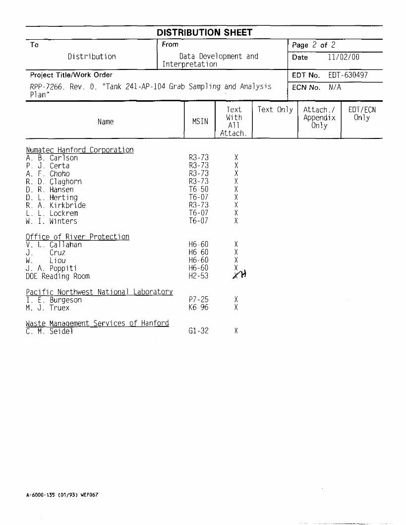
DISTRIBUTION SHEET To I From 1 Page 2 of 7
D i s t r i b u t i o n D a t a Development and Date 11/02/00 I n t e r p r e t a t i o n
Numatec Hanford CorDoration A . B . Carlson
Project Title/Work Order
RPP-7266, Rev. 0 , "Tank 241-AP-104 Grab Sampling and Analys is P1 an"
P . J . Certa A. F. Choho R . D . Claghorn D. R . Hansen D. L . He r t i ng R . A . K i r k b r i d e L . L . Lockrem W . I. Winters
O f f i c e o f R iver P ro tec t i on V . L . Callahan J . Cruz W . L i ou J . A . Popp i t i DOE Reading Room
P a c i f i c Northwest Nat ional Laboratory I . E . Burgeson M . J . Truex
Waste Manaqement Services o f Hanford C . M . Seidel
. _
EDT NO. EDT-630497 ECN No. N/A
R3-73 X R3-73 X R3-73 X
MSIN Name
R3-73 X
Text Text Only A t tach , / EDT/ECN With Appendix Only A l l Only
At tach.
T6-50 X T6-07 X R3-73 X T6-07 X T6-07 X
H6-60 X H6-60 X H6-60 X H6-60 H2-53 h P7-25 X K6-96 X
G1-32 X
A-6000-135 (01/93) WEF067

RPP-7266, Rev. 0
Tank 241 -AP-104 Grab Sampling and Analysis Plan
Andrew M . Templeton CH2M HILL Hanford Group, I n c . , Richland, WA 99352 O f f i c e o f River Pro tec t ion Contract DE-AC06-99RL14047
EDT/ECN EDT-630497 UC: 2070 Org Code: 7KN00 Contract No. : 7899-32 B&R Code: EW 3120074 Tota l Pages: 4+ Key Words: Sampling, Ana lys is , Plan
Abs t rac t : N/A
Tank 241-AP-104. Tank AP-104, AP-104. AP Farm, Grab,
TRADEMARK DISCLAIMER. Reference herein t o any speci f ic commercial product, process, o r serv ice by trade name, trademark, manufacturer, or otherwise, does not necessari ly cons t i t u te or imply i t s endorsement, recommendation, o r favoring by the United States Government o r any agency thereof o r i t s contractors o r subcontractors.
P r in ted i n the United States of America. To obta in copies of t h i s document, contact: Docunent Control Services, P.O. Box 950, Mailstop H6-08, Richland WA 99352, Phone (509) 372-2420; Fax (509) 376-4989.
Approved for Public Release
A-6400.073 (01/97) GEF321

RPP-7266 Revision 0
Tank 241-AP-104 Grab Sampling and Analysis Plan
A. M. Templeton CH2M HILL Hanford Group, Inc.
Date Published October 2000
CH2MHILL Hanford Group, Inc.
Prepared for the U.S. Department of Energy Office of River Protection

RPP-7266 Rev . 0
TABLE OF CONTENTS
1.0 SAMPLING AND ANALYSIS OBJECTIVES ...................................................................... 6
2.0 SAMPLING EVENT REQUIREMENT ................................................................................. 7 2.1 SAMPLE COLLECTION ................................................................................................ 7
3.0 LABORATORY ANALYSIS REQUIREMENTS ................................................................ 10 3.1 ANALYSIS SCHEME ................................................................................................... 10 3.2 SPECIFIC METHODS AND ANALYSES ................................................................... 11 3.3 INSUFFICIENT SAMPLE RECOVERY ..................................................................... 12
4.0 QUALITY ASSURANCE AND QUALITY CONTROL ..................................................... 28 4.1 LABORATORY OPERATIONS .................................................................................. 28 4.2 SAMPLE CUSTODY .................................................................................................... 34
5.0 EXCEPTIONS. CLARIFICATIONS. AND ASSUMPTIONS ............................................. 35 5.1 CLARIFICATIONS AND ASSUMPTIONS ................................................................ 36
6.0 ORGANIZATION ................................................................................................................. 37
7.0 DELIVERABLES .................................................................................................................. 39 7.1 FORMAT I REPORTING ............................................................................................. 39 7.2 FORMAT IV REPORTING .......................................................................................... 39
8.0 CHANGE CONTROL ........................................................................................................... 40
9.0 REFERENCES ...................................................................................................................... 42
.. 11

RPP-7266 Rev . 0
LIST OF FIGURES
Figure 1 . Characterization Change Notice ................................................................................... 41
LIST OF TABLES
Table 1 . Tank Grab Sampling Information ................................................................................... 8
Table 2 . Chemical, Radiological, and Physical Analyses: Liquid ............................................... 14
Table 3 . Chemical, Radiological, and Physical Analyses: Solids ................................................ 16
Table 4 . Detection Limits and Minimum Reportable Quantities for LAW Liquids ................... 18
Table 5 . Detection Limits and Minimum Reportable Quantities for HLW Solids ..................... 22
Table 6 . Group I Analytes (Patello et al . 1999) ........................................................................... 26
Table 7 . Quality Control Parameters for Liquid Analysis ........................................................... 29
Table 8 . Quality Control Parameters for Solids Analysis ............................................................ 32
Table 9 . Tank 241-AP-104 Project Points of Contact and Key Personnel List ........................... 37
... 111

WP-7266 Rev. 0
LIST OF TERMS
AEA AMU CHG CPO CVAA DQO DOE-RL EDTA ft g/mL GEA HEDTA HL W IC ICD ICP ICPIAES ICP/MS in. ISE kgal kL L L&H LAW LCS LFL m A4 Mgal mL
N/A MRQ
QA QC RPD RPP RSD SAP SPG
alpha energy analysis atomic mass unit CH2M HILL Hanford Group, Inc. Characterization Project Operations cold vapor atomic absorption Data Quality Objective U.S. Department of Energy, Richland Operations Office ethylenediaminetriacetic acid feet grams per milliliter gamma energy analysis N-(hydroxyethy1)-ethylenediaminetiracetic acid high-level waste ion chromatography Interface Control Document inductively coupled plasma inductively coupled plasmdatomic emission spectroscopy inductively coupled plasmdmass spectrometry inches ion-specific electrode kilogallon kiloliter liter low activity waste and high-level waste feed low activity waste laboratory control standard lower flammability limit meters molar million gallons milliliter minimum reportable quantity not applicable quality assurance quality control relative percent difference River Protection Project relative standard deviation sampling and analysis plan specific gravity
iv

RPP-7266 Rev. 0
TBD TIC TOC TWRS Wt% % pCi/g pCi/mL
pg C/mL Izg c /g
PLgk PdmL
LIST OF TERMS (Continued)
to be determined total inorganic carbon total organic carbon Tank Waste Remediation System weight percent percent microcuries per gram microcuries per milliliter micrograms carbon per gram micrograms carbon per milliliter microgram per gram micrograms per milliliter
V

RPP-7266 Rev. 0
1.0 SAMPLING AND ANALYSIS OBJECTIVES
This sampling and analysis plan (SAP) identifies characterization objectives pertaining to sample collection, laboratory analytical evaluation, and reporting requirements for samples obtained from tank 241-AP-104. The purpose of this sampling event is to obtain information about the characteristics of the contents of 241-AP-104 required to provide sample material to the Waste Treatment Contractor in accordance with Interface Control Document for Waste Treatability Samples (Interface Control Document-23 [ICD-231) (BNFL 2000) and to satisfy requirements of Low Activity Waste and High-Level Waste Feed Data Quality Objectives (L&H DQO) (Patello et ai. 1999), and Data Quality Objectives For RPP Privatization Phase I : Confirm Tank TIS An Appropriate Feed Source For Low Activity Waste Feed Batch X(LAW DQO) (Nguyen 1999a). Adams et al. (2000a) lists these DQOsiissues as the only ones pertaining to this sample event.
Grab samples will be obtained from riser 001 to provide sufficient material for the chemical analyses and tests required to satisfy these data quality objectives and ICD-23. The 2 2 2 3 Laboratory will receive samples; composite the samples; perform chemical analyses on composite samples; and provide samples to the Waste Treatment Contractor and the Process Chemistry Laboratory. The Process Chemistry Laboratory at the 222-S Laboratory Complex will perform process tests to evaluate the behavior of the 241-AP-104 waste undergoing the retrieval and treatment scenarios defined in the applicable DQOs. The Waste Treatment Contractor will perform process verification and waste form qualification tests. Requirements for analyses of samples originating in the L & H DQO process tests will be documented in the corresponding test plan (Person 2000) and are not within the scope of this SAP.
The following sections provide the general methodology and procedures to be used in the preparation, retrieval, transport, analysis, and reporting of results from grab samples retrieved from tank 241-AP-104.
6
- .- .. __.

WP-7266 Rev. 0
2.0 SAMPLING EVENT REQUIREMENT
Tank 241-AP-104 is located in the AP Tank Farm in the 200 East Area. The tank is a 3,785,400-L (1 Mgal), 23-m (75-ft) diameter double-shell underground storage tank. As of October 25,2000, the surface level ENRAF’indicated that tank 241 -AP-104 contained a total waste volume of approximately 4,202 kL (1,110 kgal). This waste volume is equivalent to 403.75 inches of waste as measured from the inside bottom of the tank). Currently, it is unknown how much solids are contained in the tank. The tank contains waste transferred from tank 241-SY-102.
Table 1 identifies the number of samples, the riser to be used for sampling, and the elevations and depths at which the samples are to be obtained.
Prior to sampling, the dome space (below the riser) shall be measured for the presence of flammable gases. The measurement shall be taken from within the dome space and the data reported as a percentage of the lower flammability limit (LFL). The results shall be transmitted to River Protection Project (RPP) Data Development and Interpretation within ten working days of the sampling event. If the results are above 25 percent of the LFL when analyzing by gas chromatography/mass spectrometry or gas-specific monitoring gauges, or above 10 percent of the LFL when analyzing with a combustible gas meter, RF’P Data Development and Interpretation shall notify the Flammable Gas Safety Project. The necessity for recurring sampling for flammable gas concentration and the frequency of such sampling will be determined by the Flammable Gas Safety Project. Any additional vapor sampling is not within the scope of this SAP.
Grab samples shall be obtained using plant operating procedure TO-080-403, Supernatant or Sludge Sampling of Waste Storage Tanh Using a Glovebag or a suitable substitute approved plant operating procedure. The procedure title and number used shall be documented in the work package.
2.1 SAMPLE COLLECTION
Four samples will be collected from each of five different waste depths from riser 001 using 500-mL bottles (total of twenty samples). If a different riser is necessary to meet sampling and analysis requirements, this change must be recorded and approved by the cognizant engineer and the tank coordinator (TC) before sampling. Table 1 provides the information for this sampling event. The exact time that each sample bottle is collected and the appearance of each sample (solids or no solids) shall be recorded on the chain-of-custody form.
If quality affecting changes to the sampling requirements must be made (including the risers or samples to be obtained), the change must be recorded and approved by the cognizant engineer and tank coordinator before sampling. This information may be recorded in the work packages.
’ ENRAF is a trademark of the ENRAF Corporation, Houston, Texas.
I

RPP-7266 Rev. 0
Sample Expected Number Sample Type’
These work packages contain the operating procedures and the chain-of-custody records for the sampling events.
Before sampling can be performed on a tank, available risers must be identified for use in the sampling event. The selected risers must be inspected and prepared to confirm their ability to be used in sampling. Safety hazards must be identified and special precautions must be taken if needed.
Sample Location
A measurement of the solids in tank is required prior to sampling. This may or may not be possible depending on the properties of the solids.
Samples are to be taken from a tank and shipped to the performing laboratory by Characterization Project Operations (CPO) in accordance with the respective work packages. The chain-of-custody forms for these work packages shall identify samples by a unique number and state the size of the sample for each sample before being shipped to the 222-S Laboratory. Pertinent sampling information (e.g., unusual waste characteristics, solids content, or detecting debris) should be noted in the comment section of the chain-of-custody form.
Characterization Project Operations should transport each sample on the same day it is collected or store the samples in a heated building (70 degrees F). A 500-mL sample bottle field blank is required during the sampling event. The laboratory shall provide the de-ionized water. The samples should be shipped to the performing laboratory within three calendar days of removing the sample from the tank. A verbal notification by CPO is to be made to the 222-S Laboratory at 373-2435 at least 24 hours in advance of an expected shipment.
Table 1. Tank Grab Sampling Information
#1
#2
#3
#4
4AP-00-1B Field Blank Riser 001 4AP-00-1 Liquid Riser 001 4AP-00-2 Liquid t 4AP-00-3 Liquid 4AP-00-4 I Liquid 4AP-00-5 1 Liquid I Riser 001 4AP-00-6 Liquid 4AP-00-7 I Liquid 4AP-00-8 I Liquid 4AP-00-9 1 Liquid 1 Riser 001 4AP-00-10 I Liquid 4AP-00-11 Liquid 4AP-00-12 I Liquid 4AP-00-13 I Liquid I Riser 001 4AP-00-14 1 Liquid
379 in 379 in
290 in 290 in 29’ 1 l”(359 in
201 in 37’ 4”(448 in) 201 in 37’ 4”(448 in) 201 i n .
113 in.
I 22’ 6”(270 in.) 1 22’ 6”(270 in.)
1 44’ 8”(536 in) 1
8

RPP-7266 Rev. 0
Sample Number
4AP-00-15
Level
Table 1. Tank Grab Sampling Information
Expected Sample Sample Sample Sample Type* Location Elevation’ Depth‘ fr Liquid 1 1 3 i n . 44’ 8”(536 in)
#5
#6
4AP-00-16 Liquid 113 in.. 44’ 8”(536 in) 4AP-00-17 Solidskiquid Riser 001 24 in. 52’ l”(625 in) 4AP-00-18 SoliddLiquid 24 i n . 52’ l”(625 in) 4AP-00-19 Solids/Liquid 24 i n . 52’ l”(625 in) 4AP-00-20 SoliddLiquid 24 in . 52’ l”(625 in) 4AP-00-21 Solidskiquid Riser 001 6 in’ 53’ 7”(643 in)
9
. ~

RPP-7266 Rev. 0
3.0 LABORATORY ANALYSIS REQUIREMENTS
The extrusion, sub-sampling, forming a composite, and analysis requirements are described below.
3.1 ANALYSIS SCHEME
Data quality objectives requirements drive the analysis of the samples. This section provides direction to the laboratory in regards to the sample handling and analysis scheme required to comply with the L&H and LAW DQOs and the sample handling required to comply with ICD- 23.
Four sets of grab samples will be collected representing 5 elevations in the tank. One set (Samples 4AP-00-02,06, 10, 14, 18) of 500-mL bottles will be used to support the requirements of the L&H DQO, and part of the LAW DQO. The second set 4AP-00-03,07, 11,15, 19 of 500- mL bottles will be archived for future support of the LAW DQO. The third and fourth sets (Samples 4AP-00-04,05,08,09, 12, 13, 16, 17,20,21) of 500-mL bottles will be provided to the Waste Treatment Plant (WTP) Contractor to support the requirements of ICD-23. Record date and times of all steps.
( I ) Record visual observations such as color and clarity of the liquid and the presence of any solid particles in the liquid. Record the volume YO of settled solids upon receipt and after 16 hours, if present. A consistent approach to this measurement shall be established. Video tape the samples at time of receipt.
(2) Closely inspect the sample for the presence and approximate volume of any potential organic layers. Record the volume of separable organic phase, if present.
(3) Package the third and fourth set of samples for shipment to the WTP contractor. Copies of the laboratory load in reports, sample chains-of-custody, and sample photographs associated with these samples must be provided to the Waste Treatment Contractor point of contact.
(4) Archive the second set of samples for the LAW DQO.
(5) Allow the remaining set of samples to settle for at least 16 hours. Record volume percent settled solids, and note any evidence of gas releases or separated liquid phases.
Prepare six separate tank composites as directed by the tank coordinator. These six composites will consist of liquid or slurry composites representative of the waste present in the grab samples.
Mix the composites and allow to settle for at least 16 hours. Record the total composite weight and volume % settled solids for each composite, and note evidence of any floating layer (an organic layer or solids) or gas generation.
(8) Submit four of the composites to the Technology Project Management Group for
(6)
(7)
10

RPP-7266 Rev. 0
testing per L&H DQO. These tests will be performed per Person (2000).
(9) Archive one of the remaining composites. (10) Separate the remaining composite by centrifugation. The responsible chemist shall
ensure that the centrifuged solids contain no separate liquid phase. Each of these composites must contain sufficient material to perform the analyses in Tables 2 and 3. If insufficient solids are present to perform all the solids analyses in Table 3, refer to Section 5.0 for a priority of the analyses.
(1 1) Analyze 3 sub-samples of the centrifuged solid fraction of each composite separated in
(12) Analyze 3 sub-samples of the liquid fraction of each composite separated in step 10
(1 3) Analyze the field blank per Table 2.
(14) Archive all remaining sample material.
step IO per Table 3.
per Table 2.
Opportunistic analyses as defined in Kristofzski (1996) are to be included when the laboratory is not operating at maximum capacity. Any decisions, observations, or deviations made to this work plan, or during the sample breakdown and analyses shall be documented in writing with justification. These decisions and observations shall be reported in the data report. The reporting formats for analyses are contained in Tables 2 and 3 and are described in Section 7.0.
A material balance shall be performed to account for all the material sampled and composited.
3.2 SPECIFIC METHODS AND ANALYSES
The analyses in Tables 2 and 3 to be performed on the tank 241-AP-104 grab samples are based on the L&H and LAW DQOs. The laboratory procedure numbers which shall be used for the analyses are included in the tables. Sample preparation procedures that may be used at the 222-S Laboratory are LA-549-141 for fusion digestion; LA-549-142 for fusion digestion followed by water leaching; LA-505-158, or LA-505-163 for acid digestion of samples; LA-504- 101 for water leach of solids; and LA-505-100 for acid digestion of solids and liquids for selenium analysis by graphite furnace atomic absorption (GFAA). The laboratory is to notify the tank coordinator once all analyses are complete.
Duplication of effort shall be avoided where practical. For example, many of the analyses required for the L&H DQO are also required by the LAW DQO. If process testing per the LAW DQO determines that dilution is not required for waste retrieval, analyses per the L&H DQO can meet the corresponding data needs of the LAW DQO. However, if process testing determines that dilution of the waste is required, then separate analyses of the diluted samples will be as specified in a test plan.

RPP-7266 Rev. 0
The L&H and LAW DQOs specify minimum reportable quantities (MRQs) for analytes listed in Tables 2 and 3. The laboratory shall notify the tank coordinator of any circumstances which prevent achieving detection limits at or below the L&H DQO’s MRQ for any analyte, and recommend a corrective course of action. The MRQs for the requested analytes are provided in Tables 3 and 4; the HLW DQO’s MRQs are provided in these tables for information only.
The L&H DQO requires repreparation and/or reanalysis of a subsample under certain conditions. Repreparation and/or reanalysis of a subsample applies to Group 1 analytes whose relative standard deviation (RSD) exceeds the criteria in Section 4 and whose concentration is greater than the MRQ. In such circumstances, only one additional analysis is required, and the results of all analyses shall be reported. The decision to reanalyze a subsample or reprepare and reanalyze a new subsample shall be made by the project coordinator based on the previous results. If after reanalysis, the RSD of all subsamples exceeds the criteria, a decision will be made on the need for further analysis by the project coordinator, the tank coordinator and the Waste Integration Team (WIT) technical point of contact. Group 1 analytes, as defined by the L&H DQO for LAW and HLW are listed in Table 5 .
3.3 INSUFFICIENT SAMPLE RECOVERY
If the amount of material recovered from samples taken from 241-AP-104 is insufficient to form the composites and perform the analyses requested in the SAP, the laboratory shall notify the tank coordinator within one working day. It is unknown how much solids are contained in the tank. Based upon the results of the sampling (amount of solids), a priority of the analyses and/or compositing scheme will be provided to the laboratory. Any analyses prescribed by the SAP, but not performed, shall be identified in the appropriate data report with justification provided for nonperformance.
If the amount of centrifuged solids obtained from the composite solids is not sufficient to perform the analyses required by Table 3, analyses shall be performed in order of priority until all sample is consumed. Analytical priorities for the centrifuged solids, from highest priority to lowest, are listed below. For multi-analyte methods, all analytes required by Table 3 are requested. However, if material constraints require prioritization of the analytes, the highest priority analytes are also provided. The analyses should be performed on three subsamples as described in Section 3.1 unless there is insufficient sample to complete the first ten analytical methods listed below. If there is insufficient material, only two subsamples shall be analyzed.

RPP-7266 Rev. 0
If the same acid digest preparation is used for both inductively coupled plasmdatomic emission spectroscopy (ICP/AES) and inductively coupled plasmdmass spectrometry (ICPMS), the analytical priorities are:
(1) ICP/AES (AI, Ba, Ca, Cd, Cr, Fe, K, Na, Ni, P, Pb, S, and U are highest priority analytes)
(2) ICP/MS (Ba, K, La, and 99Tc are highest priority analytes)
(3) Gamma Energy Analysis (GEA) (Is4Eu, 6nCo, and I3’Cs are highest priority analytes) (4) Total alpha
(5)
(6) (7) Alpha Energy Analysis (AEA) (238Pu, 239’240Pu, and 24’Am are highest priority AEA
analytes)
(8) Wt. % oxides
(9) Ion Chromatography (IC)
(10) Total inorganic carbodtotal organic carbon (TIC/TOC) by furnace oxidation and persulfate oxidation
99Tc by separation and liquid scintillation and 90Sr by separation and beta counting I29 I by separation and GEA
(11) Hg (12) Weight percent solids
(13) CN
If separate acid digest preparations are required for ICP/AES and ICP/MS, the priority of the ICPMS analysis will be lowered to between TIC/TOC and Hg.


t-t
$ c

T 1
e 2
2 $ 1 8
5 . I I- r - - \ B 0 I
c
2 0
B 0


RPP-7266 Rev. 0
L
ICPIMS 7.5E-01 2.3E+00 PdmL 7.5E-01 2.3 E+OO PdmL
ICP/MS 7.5E-01 2.3E+00 P!&L
As B ICPIMS Ba
Be ICPMS 7.5E-01 2.3E+00 u d m l .
Table 4. Detection Limits and Minimum Reportable Quantities for LAW Liquids (4 Sheets)
Bi ;Ca Cd Ce c o Cr c u
IICPIAES I 2.5E+01 I 7.5E+01
r -D
ICPIAES 5 SE+O 1 1.7E+02 PdmL ICPIAES 5.OE+01 1.5E+02 PdmL ICPIAES 2.5E+00 7.5 E+OO PdmL ICP/MS 7.5E-01 2.3E+00 PdmL ICP/MS 7.5E-01 2.3E+00 PdmL ICPIAES 5.OE+00 1.5E+01 PdmL ICPIAES 5.5E+00 1.7E+01 udmL
18

RPP-7266 Rev. 0
99Tc (total) 99Tc (pertechnetate) 12%b '%n
~~
Table 4. Detection Limits and Minimum Reportable Quantities for LAW Liquids (4 Sheets)
ICPMS 5.OE-04 1 SE-03 pCi/mL NS TBD TBD pCi/mL GEA 5.6E-01 1.7E+00 pCi1mL ICPMS 2.OE-03 6.OE-03 uCilmL
~~~
Is2Eu Is4Eu '"Eu 23'Pa 2 3 3 ~
I 1291 I G E A I 5.8E-06 I 1.8E-05 1 uCi/mL I
GEA TBD TBD pCi1mL GEA 6.5E-03 2.OE-02 pCi/mL GEA 3.OE-02 9.OE-02 pCi1mL ICPIMS TBD TBD pCi/mL ICP/MS 1.4E-04 4.2E-04 pCi/mL
1 1 3 7 ~ ~ I G E A I 1.3E-01 I 3.9E-0 1 I uCi/mL I
19

RPP-7266 Rev. 0
Table 4. Detection Limits and Minimum Reportable Quantities for LAW Liquids (4 Sheets)
Minimum Reportable r Estimatedquantitation i
LimWklinimnm 1 _ _
uCi/mI.
_--.
Analyte Method' Deteehble Activity 1 Quantity ICPIMS 4.4E-05 1.2 E-04
so, IC 7.7E+02 2.3E+03 Pg/mL total alpha Prop. counting 7.5E-02 2.3E-01 pCi/mL total beta Beta counting TBD TBD pCi/mL
20

RPP-7266 Rev. 0
Table 4. Detection Limits and Minimum Reportable Quantities for LAW Liquids (4 Sheets) I
Eeiimated Quantitation
Detwtable Activity Minimum Reportable
L Analyte total inorganic Persulfate/ pg/mL carbon furnace
oxidation I 1 . - ! furnace oxidation
Notes:
AEA = alpha energy analysis CVAA = cold vapor atomic absorption GEA = gamma energy analysis IC = ion chromatography ICPIAES = inductively coupled plasmdatomic emission spectroscopy ICP/MS = inductively coupled plasma /mass spectrometry ISE = ion-specific electrode liquid scint. = liquid scintillation NS = not specified prop. counting = proportional counting TBD =to be determined
' The method is that which is listed in the DQO and may differ from the method used by the Laboratory for analysis.
Combined analysis of 219Pu and 2 r o P ~

WP-7266 Rev. 0
Table 5. Detection Limits and Minimum Reportable Quantities for HLW Solids (4 Sheets)
22

RPP-7266 Rev. 0
Table 5. Detection Limits and Minimum Reportable Quantities for HLW Solids (4 Sheets)

RF'P-7266 Rev. 0
Total alpha IAlpha counting
Table 5. Detection Limits and Minimum Reportable Quantities for HLW Solids (4 Sheets)
2.OE-01 6.OE-01 pCi/g
, . . , , I . . . ,
Total beta IBeta counting 7.OE+00 2.1E+01 pCi/g
24

RPP-7266 Rev. 0
ICPIMS = inductively coupled plasmdmass spectrometry ISE = ion-specific electrode sep. =separation
'The method is that which is listed in the DQOs and may differ from the method used by the Laboratory for analysis.
'Detection limits and MRQs for the L&H DQO. Where HLW DQO requirements differ from those listed, the corresponding HLW requirement is shown in parentheses. The HLW requirements are listed for information only.
'NS, not stated for the L&H DQO. In the event that testing shows that dilution is not required to meet waste transfer requirements, then the HLW MRQs apply. If process testing determines that dilution is required for transfer, requirements for analysis of the diluted waste will he as per the test plan.
'Combined analysis of % and 9oY
'Combined analysis of 9'mNb and "Zr
6Combined analysis of "'Sh and "'"Te
'Combined analysis of "'Cs and '""Ba
'Combined analysis of "'Pu and 240Pu
'Combined analysis of z4zAm, z42mAm, andi4'Cm
25

RPP-7266 Rev. 0
Analyte
Table 6. Group I Analytes (Patello et al. 1999) (2 sheets)
LAW (liquids) HLW (solids)
oa Be Ca Cd Ce CI CN- c o
A
X X X
X X X
X X
L S
c u F- Fe
K Hg
L1 I I A j Mn I Ix I
A
X X X X X X
Mo Na Nd "3
Ni 1 NO: Ix Ix
X
X X
X
X
NO; Pb PO,"
X X X X
NO; Pb PO,"
>e I I A so,-* Ix I
X X X X
Pr Pu Rb Sb
X X X X
26
Pr Pu Rb Sb
X X X X
+
Sr Ta Tc
X X x
Te Ix

RPP-7266 Rev. 0
Analyte LAW (liquids)
Table 6. Group I Analytes (Patello et al. 1999) (2 sheets)
HLW (solids)
1 uc A A
U X V X W X -
TI
-n IA I '4c I X - Y o X X "Sr X X 991.. v " IC IA I A
I2'Sb I lx I I " I I I A I

RPP-7266 Rev. 0
4.0 QUALITY ASSURANCE AND QUALITY CONTROL
Processes, services, activities, and conditions adverse to the quality which do not conform to requirements specified in this SAP or references herein shall be controlled to prevent inadvertent use. Nonconforming sampling and analysis processes shall be identified, controlled, reported, and the disposition taken as required by the Nonconformance Item Reporting and Control (CHG 1999).
4.1 LABORATORY OPERATIONS
Laboratories performing analyses in support of this SAP shall have approved and implemented Quality Assurance (QA) Plans. These QA plans shall meet the Hanford Analytical Services Qualify Assurance Requirements Document (DOE-RL 1998) minimum requirements as the baseline for laboratory quality systems. The 2223 Laboratory Quality Assurance Plan (Markel 2000) specifies the requirements for assuring the quality of sample analysis conducted at the 222-S Laboratory. Quality requirements for conducting Characterization Project sampling and analysis are described in Tank Waste Remediation System Characterization Project, Qualify Policies (Board 1998) and this SAP. Characterization Project sampling and analysis shall be conducted in conformance with these requirements.
Analytical quality control (QC) requirements (duplicates, spikes, blanks, laboratory control samples) are identified in Tables 1,2,6, and 7. The laboratory shall also use calibration and calibration check standards appropriate for the analytical instrumentation being used (see DOE-RL [1998] for definitions of QC samples and standards) or procedure/method specfic QC criteria as applicable. The criteria presented are goals for demonstrating reliable method performance. It is understood that the laboratory will follow its internal QC system for required actions whenever QC failures occur. If sample QC failures occur, or if all analyses cannot be performed (e.g., insufficient sample), analysts shall consult with supervisors/customers to determine the proper action. The laboratory should provide a suggested course of action at that time. All QC failures and limitations on the associated data shall be discussed in the narrative of the data report. Proper notification of all data not meeting QC requirements shall be included with the data.

RPP-7266 Rev. 0
Archive all unused sample portions. Table 7. Quality Control Parameters for Liquid Analysis (2 Sheets)
Anriyfieal Analyto Technique
1 Seoarable organic lvisual Specific gravity Gravimetry Wt% dissolved solids Gravimetry Wt% oxide Gravimetry Ag, AI, As, B, Be, Ba, Bi, ICP/AES Ca, Cd, Ce, Cr, Cu, Eu, Fe, K, La, Li, Mg, Mn, Mo, Nd, Ni, P, Pb, S, Sb, Se, Sr, Si, Th, Ti, TI, U, V, Zn, Zr Na ICP/AES As, B, Ba, Be, Ce, Co, La, ICPiMS Li, Mo, Pd, Pr, Rb, Rh, Ru, Sb, Se, Ta, Te, Th, TI, v, w, 9 0 ~ ~ ~ , %n, 238u, 24'AMU, 242AMU, 99Tc Cs, Eu ICPiMS 23'Pa ICPiMS 233U, 234U, 23sU, 236U, 237Np, ICPMS
243AMU Br-, Cl , F, NO;, NO, '- Po,", so;', formate, oxalate, acetate, citrate, NTA
Sb, Se GFAA NH,/",' ISE, standard
additions OH- Potentiometric
titration TIC, TOC Persulfate and
furnace oxidation CN- Distillation/
colorimetric
IC
H s CVAA
QC Acceptance C LCS S P h
%Recovery _ _ __ %Recovery
80 - 120%
80 - 120% 75 - 125%
80- 120% I 75 - 125%
NS NS TBD TBD
90 - 110% 75 - 125% I
80 - 120% 1 75 - 125%
80 - 120% 75 - 125%
N/A - I2O% ~
80- 120% 1 75- 125%
80 - 120% 75 - 125%
29
.- . teria
Triplicate RSD1
.
NIA NIA 121% TBD 115%
<3.5% 4 5 %
NS TBD 4 5 %
4 5 %
<15% 4 5 %
4 5 %

RPP-7266 Rev. 0
Total beta 90Sr
2 3 8 ~ ~ . 2 3 9 1 2 4 0 ~ ~ . 241Am.
Archive all unused sample portions. Table 7. Quality Control Parameters for Liquid Analysis (2 Sheets)
Beta counting 70 - 130% 70 - 130% <15% Separatiodbeta 75 - 125% NIA <15% counting SeparatiodAEA NS NIA 115%
~ -- . .- _ _ -.___I .. . . . I--
Total alpha Proportional 70 - 130% 70-130%
242cm, 243i244cm
'H ISeparatiodliquid 1 80 - 120% I NS 4 5 %
I lcountina I I I I
I4c scintillation
scintillation Separatiodliquid 80 - 120% 75 - 125% 4 5 %
79Se 99Tc 9 9 T ~ , 99Tc (pertechnetate)
~~
Liquid scintillation NP NIA 4 5 % ICPIMS 80 - 120% 70 - 130% 4 5% Separationheta 80 - 120% 70 - 130% <I 5%
6oCo, I3'Cs, "'EU, Is4Eu, "'Eu 12'Sb 1291
count GEA NS NIA <15%
GEA TBD TBD TBD SeparatiodGEA NS NIA <15%
Notes: AEA =alpha energy analysis AMU = atomic mass unit CVAA =cold vapor atomic absorption GEA = gamma energy analysis GFAA = graphite furnace atomic absorption IC = ion chromatography lCP/MS = inductively coupled plasmdmass spectrometry ICP/AES = inductively coupled plasmdatomic emission spectroscopy ISE = ion specific electrode LCS = laboratory control standard N/A =not applicable NS =not specified by DQO (Patello et al. 1999) TBD = to be determined TIC =total inorganic carbon TOC = total organic carbon RPD = relative percent difference RSD = relative standard deviation Wt% = weight percent

RPP-7266 Rev. 0
‘RSD requirement if the sample result is at least IO times the instrument detection limit. RSD = (standard deviation of the meadmean) x 100%

RPP-7266 Rev. 0
Table 8. Quality Control Parameters for Solids Analysis (2 Sheets)
Bi, Ca, Cd. Ce, Cr, Cu, Fe, K, La, Mg, Mn, Li, Nd, Ni, P, Pb, S, Sb, Se,
Rb, Rh, Ru, S, Sb, Se, Ta, Te, Th, T1, V, W, Y,

RPP-7266 Rev. 0
_____
Solids Fraction Analytical Technique
Table 8. Quality Control Parameters for Solids Analysis (2 Sheets) I..I___ ” - QC Acceptance Criteria
LCS Yo ’ Spike% Tripficate Recovery 1 Recovery RSD‘ I ‘8pu,7JmmPu, *“Am,
Notes: AEA =alpha energy analysis CVAA = cold vapor atomic absorption GEA = gamma energy analysis GFAA =graphite furnace atomic absorption IC = ion chromatography ICPlAES = inductively coupled plasmdatomic emission spectroscopy ICPiMS = inductively coupled plasmdmass spectrometry ISE = ion specific electrode LCS = laboratory control standard NIA = not applicable NS =not specified RPD =relative percent difference RSD =relative Standard Deviation TBD = t o be determined Wt% = weight percent
‘RSD requirement if the sample result is at least IO times the instrument detection limit. RSD = (standard deviation /mean) x 100%
SeparatiodAEA NS NIA <15%

RPP-7266 Rev. 0
4.2 SAMPLE CUSTODY
The chain-of custody form is initiated by the sampling team as described in the work package. Samples are shipped in per WHC-SD-TP-SARP-001, Safefy Analysis Reportfor Packaging (Onsite) Sample Pig Transport System, and sealed with a Waste Tank Sample Seal (see below).
I
Date of Sampling: Shipment No.: I Serial No.:
[ Time of Sampling:
The sealed and labeled samples are shipped to the laboratory along with the chain-of-custody form. The receipt and control of samples in the 222-S Laboratory are described in laboratory procedure LO-090-101.
34
.I"- --

RPP-7266 Rev. 0
5.0 EXCEPTIONS, CLARIFICATIONS, AND ASSUMPTIONS
The L&H DQO requests analysis of both solid and liquid fractions from static Phase 1 candidate feed source tanks. Tank 241-AP-104 is assigned as a LAW feed candidate but the solids remaining after dissolution may be considered HLW, therefore the solids will be analyzed against the HLW section of the L & H DQO.
As understood by the customer the analyses of the liquids for volatile organic compounds as stated in the Data Quality Objectives for Regulatory Requirements for Hazardous and Radioactive Air Emissions Sampling and Analysis (Air DQO) (Mulkey 1999) will not be performed.
The L&H DQO requires full dissolution of solids samples for analysis. However, some of the analyses in Table 2 can only be performed on water digests of solids; full dissolution of the sample for analysis is not currently possible for these analytes. These analytes are: TOC (and total carbon) by furnace oxidation, anions by IC, ammonia, tritium, carbon-14, and iodine-129. A fusion digestiodwater leach preparation has recently been developed at the 222-S Laboratory and, if implemented, may be used for the iodine-129 analysis.
Many of the analyses performed in triplicate as directed by the L&H DQO are also required in duplicate by the HLW DQO. Per customer request, duplication of effort is to be avoided by performing these analyses in triplicate as directed by the L&H DQO to satisfy the requirements of the HLW DQO in the event that dilution is not required. Tables 2 and 7 reflect compromises between these DQO requirements to satisfy the affected programs. Several analytes being measured by ICPMS required by the L&H DQO will take the place of ICP/AES analyses for solids (As, B, Be, Ce, Co, Cs, Li, Mo, Pr, Rb, Sb, Se, Ta, Te, Th, TI, V) required by the HLW DQO.
The tables identify many analytes to be determined by ICPMS because this technique has the sensitivity to meet the desired MRQs. However if the concentration of the analyte is high enough, the quality of the ICP/AES results will be as good as or better than the ICPMS data. Because ICP/MS is based on the measurement of different element isotopes, the total amount of an element must be determined by summing the isotopes or by calculations assuming the natural abundance of the isotopes. However, in the production of nuclear materials these natural abundances are changed, particularly around the mass peaks of the fission product yield curves (AMU-90 and -137). The presence of the fission products in the samples can lead to unnatural isobaric interference that can lead to inaccuracies in the measurements. Another potential interference to the ICPMS method is in the low ( < S O AMU) atomic mass range where polyatomic species and ionized species from the argon plasma gas can cause interference problems. Elements in this region may be determined easier and more accurately using ICPIAES if the concentrations in the sample are high enough. Because it is not possible to precisely predict what trace analytes will be present in high enough concentrations for ICP/AES analysis, ICP/AES and ICP/MS are being requested for all possible analytes. For liquid samples, the following elements cannot be analyzed by ICP/AES at the required MRQs: As, B, Ba, Be
35

RPP-7266 Rev. 0
(borderline), Ce, Co, K, La, Li, Mo, Sb, Se, Th, TI, and V. For solid samples the following elements cannot be analyzed by ICP/AES at the required MRQs: Ag (borderline), As, B, Ce, Co, La (borderline), Li, Mo, Na (borderline), Nd (borderline), S (borderline), Sb, Se, Th, TI, U (borderline), V, Y , and Zn (borderline). The following analytes are expected to be semi- quantitative for the ICP/MS method: Ag, Ba, Mo, Nd, Pd, Rb, Ru, Sb, Se, Te, and *"Pa. Sb and Se can be performed by graphite furnace atomic absorption (GFAA) and are, therefore, requested by that method.
Spikes and standards are not available for all the ICP/MS analytes. Pre- and post-digestion standards and spikes are analyzed by ICPMS for the following elements and isotopes:
0
0
Solids: As, Be, Mo, Pd, Pr, Rb, Rh, Ru, Sb, Se, Ta, Te, TI, V, W, 238U, and 232Th
Liquids: As, Ba, Be, Ce, Co, Eu, La, Li, Mo, Pd, Pr, Rb, Rh, Ru, Sb, Se, Ta, Te, TI, V, W,238U, and 232Th.
Only post-digestion standards and spikes are used for the following: 0
Solids: 239Pu, 237Np, 241Am, "'Sn, 99Tc, "3Cs, 93AMU, and '"AMU
Liquids: 239Pu, 237Np, 241Am, "'Sn, 99Tc, 133Cs, and 90AMU.
The 222-S laboratory does not have analytical methods for ''Ni, 63Ni, I2%b, IZ6'"Sb, '*'"Sn, 93Nb, or 93Zr. The 222-S laboratory has indicated that it is unlikely it can meet the <3.5% RSD for Na.
5.1 CLARIFICATIONS AND ASSUMPTIONS
The laboratory is requested to report all analytical results recovered from multi-analyte methods, including the inductively coupled plasma - atomic emission spectroscopy (ICP/AES), gamma energy analysis (GEA), and ion chromatography (IC) analyses, even though only specific analytes are requested. These opportunistic analyses (Kristofzski 1996) should be reported only if no additional preparatory work is required (e.g., running additional standards) and if the associated QC results (blanks, standards, and spikes, as appropriate) are reported. No reruns or additional analyses should be performed to improve recovery for analytes not specifically requested in Tables 1 or 2.

RPP-7266 Rev. 0
Coordinator 222-S Project Coordinator for
2 2 2 4 Laboratory Point of Contact (day shift) 22243 Laboratory Point of
24 1 -AP- 1 04
6.0 ORGANIZATION
Interpretation (CHG) Analytical Production (FH)
Analytical Services (FH)
Analytical Services (FH)
R. A. Esch, 373-4314
R. K. Fuller, 373-1883
222-S Laboratory Shift
The organization and responsibility of points of contact and key personnel involved with this tank 241-AP-104 characterization project are listed in Table 8.
Contact
Table 9. Tank 241-AP-104 Project Points of Contact and Key Personnel List
. . I Manager, 373-2435
Responsibility I Organization 1 Individual RPP 241-AP-104 Tank I RPP Data Development and I A. M. Templeton, 373-5589
Contact ' I Shift Manager, 373-2689
Grab Sampling Cognizant Engineer Data Management
Process Control Point of Contact for Immediate Notifications Technology Project Management Point of Contact WFD Point of Contact Waste Treatment Contractor
Operations (CPO) Characterization Project Operations (CPO) Manager, Data Development and Interpretation (CHG) RPP Process Control (CHG)
R G. Brown, 373-5694
J. G. Field, 376-3753
On-Call Process Engineer, 85-9654 (pager)
W. I. Winters, 373-1951
J. H. Baldwin, 373-4533 M. E. Johnson, 371-3621
Acting Manager, Technology Project Management ("C) Retrieval Engineering (CHG) Tank Waste Treatment
Contact Field Operations Interface
Point of Contact WIT Technical Point of
I Operations Project (CHG) I PNNL I I. E. Burgeson, 372-3650
RPP CPO Requirements Planning and Support (CHG)
J. G. Douglas, 372-0989
37

RPP-7266 Rev. 0
WFD =Waste Feed Delivery WIT = Waste Integration Team
38
..

RPP-7266 Rev. 0
7.0 DELIVEFUBLES
All analyses will be reported as Formats I, or IV as indicated in Tables 1 and 2. Additional information regarding reporting formats is given in Adams et al. (2000b).
7.1 FORMAT I REPORTING
Tables 1 and 2 contain the notification limits for each analyte. Any results exceeding their notification limits shall be reported via telephone by the 222-S Laboratory Analytical Production Team to the On-Call Process Engineer and/or the East Tank Farm Operations shift manager as soon as the data are obtained and reviewed by the responsible scientist. This verbal notification must be followed within one hour by electronic notification to the tank farm operations shift manager, the River Protection Project (RPP) Data Development and Interpretation manager, the On-Call Process Engineer, and the tank coordinator responsible for the tank. Additional analyses for verification purposes may be contracted between the performing laboratory and the tank coordinator by either a revision to this SAP or by a letter.
7.2 FORMAT IV REPORTING
The format 1V report shall be a data package reporting the results of analyses performed and will resemble a regulatory data package without third party validation. The data package should be prepared by tank and include the data for all samples, including (as applicable) formation of composites, and associated blanks taken and analyzed for this sampling event. The recommended reporting format and the raw data that shall be included are given in Section A5.0 of Adams et al. (2000b). The data package shall be issued within 150 days from the date the last sample is received at the laboratory. The raw data shall be accessible to the program in accordance with the laboratory’s Records Inventory and Disposition Schedule and until the respective waste tank is closed or the waste is treated. The data package shall be released via an engineering data transmittal and a copy shall be delivered to the Tank Characterization and Safety Resource Center in compact disk read-only memory format if available.
In addition to this data package, an electronic version of the analytical results shall be provided to the Tank Characterization Database following issuance of the final data package. The data must be available to the Washington State Department of Ecology via the Tank Characterization Database within seven (7) calendar days of release of the data package. The electronic version shall be in the standard electronic format (Lang et al. 1999).

RPP-7266 Rev. 0
8.0 CHANGE CONTROL
Under certain circumstances, it may become necessary for the performing laboratory to make decisions concerning a sample without review of the data by the customer or the Characterization Project. All significant changes shall be documented by RF'P Data Development and Interpretation via an Engineering Change Notice to this SAP, by a letter, or on the Characterization Change Notice form (see Figure 1). Characterization Change Notices may also be initiated by the 222-S Laboratory. All changes shall also be clearly documented in the final data report. Insignificant changes may be made by the tank or project coordinator by placing a notation in the permanent record (Le., note change in the extrusion logbook or memorandum to file). Significance is determined by the tank coordinator.
Additional analysis of sample material from this characterization project performed at the request of the Characterization Program shall be performed following a revision of this SAP or issuance of a letter.
40
~ _ -

RPP-7266 Rev. 0
Figure 1. CHARACTERIZATION CHANGE NOTICE
Document:
Change Number:
ECN to TSAF' Required?
Requestor: Date:
Samples Impacted:
Proposed Change:
Reason for Change:
Date Change Effective:
Schedule Impact:
Authorization:
Tank Coordinator:
Project Coordinator:
2 2 2 4 Client Services:
Other:
Date:
Date:
Date:
Date:

RPP-7266 Rev. 0
9.0 REFERENCES
Adams, M. R., J. G. Douglas, N. L. H u h , and J. W. Hunt, 2000a, Fiscal Year 2001 Tank Characterization Technical Sampling Basis and Waste Information Requirements Document, RPP-5832, Rev. 0, CH2M HILL Hanford Group, Inc., Richland, Washington.
Adams, M. R., J. W. Hunt, and R. R. Thompson, 2000b, Letter of Intent for River Protection Project (RPP) Characterization Program: Process Engineering, Hanford Analytical Services, Characterization Project Operations and Quality Assurance, RPP-5539, Rev. 0, CH2M HILL Hanford Group, Inc., Richland, Washington.
BNFL, 2000, Interface Control Document for Waste Treatability Samples, BNFL-5 193-ID-23, Rev. 3cr1, BNFL Inc., Richland, Washington.
Board, D.C., 1998, Tank Waste Remediation System, Characterization Project, Quality Policies, HNF-SD-WM-QAPP-025, Rev. 4, Lockheed Martin Hanford Corporation, Richland, Washington.
CHG, 1999, Nonconformance Item Reporting and Control, RPP-PRO-298, Rev. 0, CH2M HILL Hanford Group, Inc., Richland, Washington.
DOE-RL, 1998, Hanford Analytical Services Quality Assurance Requirements Document, DOE/RL-96-68, Rev. 2, U.S. Department of Energy, Richland Operations Office, Richland, Washington.
Kristofzski, J. G., 1996, Directions for "Opportunistic Analyses, " (Interoffice memorandum 75310-96-168, to J. H. Baldwin et al., September 1 l), Westinghouse Hanford Company, Richland, Washington.
Lang, L. L., Bobrowski, S. F., and S. J. Harris, 1999, Standard Electronic Format SpecEfication for Tank Characterization Database Loader, Version 2.4, HNF-3638, Rev. 1, prepared by Pacific Northwest National Laboratory for Lockheed Martin Hanford Corporation, Richland, Washington.
Markel, L. P., 2000,222-S Laboratory Quality Assurance Plan, HNF-SD-CP-QAPP-016, Rev. 4, Fluor Hanford, Inc., Richland, Washington.
Mulkey, C. H., 1999, Data Quality Objectives for Regulatory Requirements for Hazardous and Radioactive Air Emissions Sampling and Analysis, HNF-SD-WM-DQO-021, Rev. 1, Lockheed Martin Hanford Corp., for Fluor Daniel Hanford, Inc., Richland, Washington.
Nguyen, D. M., 1999a, Data Quality Objectives for TWRS Privatization Phase I : Confirm Tank T i s an Appropriate Feed Source for Low-Activity Waste Feed Batch X , HNF-1796, Rev 2, Lockheed Martin Hanford Corporation, Richland, Washington
42

RPP-7266 Rev. 0
Patello, G. K., M. J. Truex, and K. D. Wiemers, 1999, Low-Activig Waste and High Level Waste Feed Data Quality Objectives, PNNL-12 163, Pacific Northwest National Laboratory, Richland, Washington.
Person, J. C., 2000, Generic Test Plan for Solubility Screening Tests of Hanford Tank Waste, RPP-5378, Rev. 0, Fluor Hanford, Inc., Richland, Washington.


![Gurps 3e - Swat [Text Only]](https://img.pdfslide.net/doc/110x75/577cd3df1a28ab9e7897b2ad/gurps-3e-swat-text-only.jpg)