Embed Size (px)
Citation preview
2
45
3 33 34
01 08 10 11 18 19 02 04 05
31 51 52 57 35 56 09 76
General Catalogue Detection 2021-2022
FC series position switches
Selection diagram
1NO-1NC
snap action
1NO+1NC
slow action
2NC
slow action
External gasket Ball Ø 8 mm,
stainless steel
Ball Ø 12.7 mm,
stainless steel
Glass fibre rod
Adjustable
lever
Adjustable
safety lever
Rope switch for
signalling
Rope switch for
signalling
Product options
Sold separately as accessory
CONDUIT ENTRY
ACTUATORS
CONTACT
BLOCKS
Threaded conduit entry
M2 M20x1.5 (standard)
PG 11
With cable gland
K23for cables
Ø 6 … 12 mm
K27for cables
Ø 3 … 7 mm
With M12 metal connector
K50 5-pole, bottom
2
46
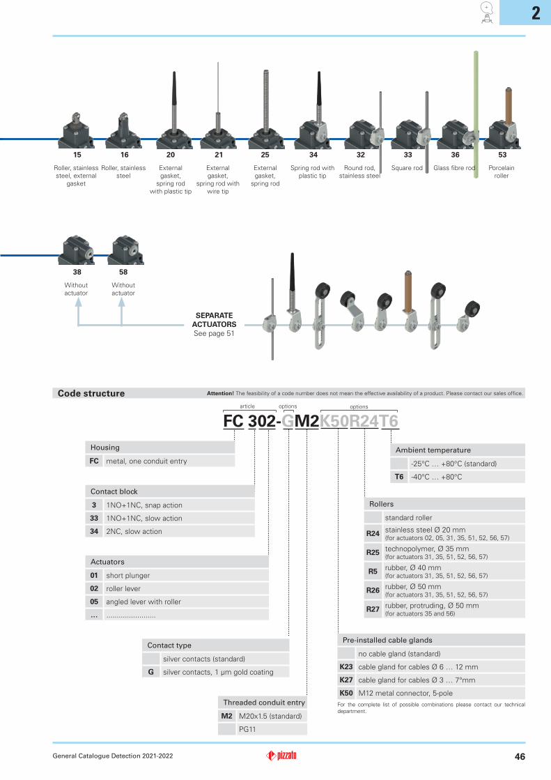
FC 302-GM2K50R24T6
General Catalogue Detection 2021-2022
Actuators
01 short plunger
02 roller lever
05 angled lever with roller
… ........................
Threaded conduit entry
M2 M20x1.5 (standard)
PG11
Contact type
silver contacts (standard)
G silver contacts, 1 µm gold coating
Housing
FC metal, one conduit entry
Code structure
Contact block
3 1NO+1NC, snap action
33 1NO+1NC, slow action
34 2NC, slow action
SEPARATE
ACTUATORS
See page 51
Pre-installed cable glands
no cable gland (standard)
K23 cable gland for cables Ø 6 … 12 mm
K27 cable gland for cables Ø 3 … 7°mm
K50 M12 metal connector, 5-pole
For the complete list of possible combinations please contact our technical
department.
15 16 20 21 25 34 32 33 36 53
Roller, stainless
steel, external
gasket
Roller, stainless
steel
External
gasket,
spring rod
with plastic tip
External
gasket,
spring rod with
wire tip
External
gasket,
spring rod
Spring rod with
plastic tip
Round rod,
stainless steel
Square rod Glass fibre rod Porcelain
roller
38 58
Without
actuator
Without
actuator
article options options
Ambient temperature
-25°C … +80°C (standard)
T6 -40°C … +80°C
Rollers
standard roller
R24stainless steel Ø 20 mm (for actuators 02, 05, 31, 35, 51, 52, 56, 57)
R25technopolymer, Ø 35 mm (for actuators 31, 35, 51, 52, 56, 57)
R5rubber, Ø 40 mm (for actuators 31, 35, 51, 52, 56, 57)
R26rubber, Ø 50 mm (for actuators 31, 35, 51, 52, 56, 57)
R27rubber, protruding, Ø 50 mm (for actuators 35 and 56)
Attention! The feasibility of a code number does not mean the effective availability of a product. Please contact our sales office.
2
47 General Catalogue Detection 2021-2022
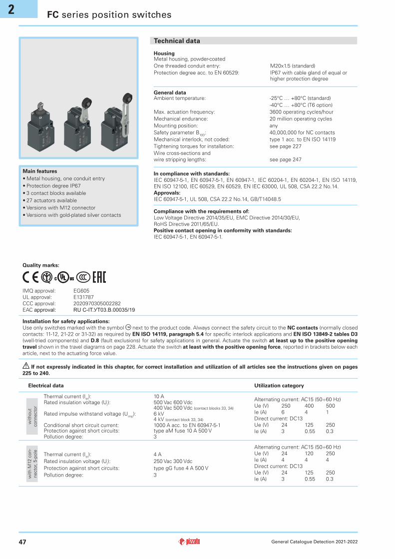
Main features
•Metal housing, one conduit entry
•Protection degree IP67
•3 contact blocks available
•27 actuators available
•Versions with M12 connector
•Versions with gold-plated silver contacts
Electrical data Utilization category
Alternating current: AC15 (50÷60 Hz)
Ue (V) 250 400 500
Ie (A) 6 4 1
Direct current: DC13
Ue (V) 24 125 250
Ie (A) 3 0.55 0.3
General dataAmbient temperature: -25°C … +80°C (standard)
-40°C … +80°C (T6 option)
Max. actuation frequency: 3600 operating cycles/hour
Mechanical endurance: 20 million operating cycles
Mounting position: any
Safety parameter B10D
: 40,000,000 for NC contacts
Mechanical interlock, not coded: type 1 acc. to EN ISO 14119
Tightening torques for installation: see page 227
Wire cross-sections and
wire stripping lengths: see page 247
HousingMetal housing, powder-coated
One threaded conduit entry: M20x1.5 (standard)
Protection degree acc. to EN 60529: IP67 with cable gland of equal or higher protection degree
FC series position switches
Quality marks:
IMQ approval: EG605
UL approval: E131787
CCC approval: 2020970305002282
EAC approval: RUC-IT.УT03.В.00035/19
Installation for safety applications:
Use only switches marked with the symbol next to the product code. Always connect the safety circuit to the NC contacts (normally closed
contacts: 11-12, 21-22 or 31-32) as required by EN ISO 14119, paragraph 5.4 for specific interlock applications and EN ISO 13849-2 tables D3
(well-tried components) and D.8 (fault exclusions) for safety applications in general. Actuate the switch at least up to the positive opening
travel shown in the travel diagrams on page 228. Actuate the switch at least with the positive opening force, reported in brackets below each
article, next to the actuating force value.
Compliance with the requirements of:
Low Voltage Directive 2014/35/EU, EMC Directive 2014/30/EU,
RoHS Directive 2011/65/EU.
Positive contact opening in conformity with standards:
IEC 60947-5-1, EN 60947-5-1.
In compliance with standards:
IEC 60947-5-1, EN 60947-5-1, EN 60947-1, IEC 60204-1, EN 60204-1, EN ISO 14119,
EN ISO 12100, IEC 60529, EN 60529, EN IEC 63000, UL 508, CSA 22.2 No.14.
Approvals:
IEC 60947-5-1, UL 508, CSA 22.2 No.14, GB/T14048.5
If not expressly indicated in this chapter, for correct installation and utilization of all articles see the instructions given on pages
225 to 240.
without
connecto
r
Thermal current (Ith): 10 A
Rated insulation voltage (Ui): 500 Vac 600 Vdc
400 Vac 500 Vdc (contact blocks 33, 34)
Rated impulse withstand voltage (Uimp
): 6 kV4 kV (contact block 33, 34)
Conditional short circuit current: 1000 A acc. to EN 60947-5-1Protection against short circuits: type aM fuse 10 A 500 VPollution degree: 3
Alternating current: AC15 (50÷60 Hz)
Ue (V) 24 120 250
Ie (A) 4 4 4
Direct current: DC13
Ue (V) 24 125 250
Ie (A) 3 0.55 0.3
Thermal current (Ith): 4 A
Rated insulation voltage (Ui): 250 Vac 300 Vdc
Protection against short circuits: type gG fuse 4 A 500 V
Pollution degree: 3with M
12 c
on-
ne
cto
r, 5
-pole
Technical data
2
48
4
1
2
35
4
1
2
35
4
1
2
35
Electrical Ratings: Q300 pilot duty (69 VA, 125-250 V dc)A600 pilot duty (720 VA, 120-600 V ac)
Environmental Ratings: Types 1, 4X, 12, 13
For all contact blocks except 2 and 3 use 60 or 75°C copper (Cu)
conductors, rigid or flexible, wire size 12, 14 AWG. Tightening torque
for terminal screws of 7.1 lb in (0.8 Nm).
For contact blocks 2 and 3 use 60 or 75°C copper (Cu) conductors,
rigid or flexible, wire size 14 AWG. Tightening torque for terminal
screws of 12 lb in (1.4 Nm).
General Catalogue Detection 2021-2022
Please contact our technical department for the list of approved products.
Features approved by IMQ Features approved by UL
Rated insulation voltage (Ui): 500 Vac
400 Vac (for contact blocks 33, 34)
Conventional free air thermal current
(Ith):
10 A
Protection against short circuits: type aM fuse 10 A 500 V
Rated impulse withstand voltage (Uimp
): 6 kV
4 kV (for contact blocks 33, 34)
Protection degree of the housing: IP67
MV terminals (screw terminals)
Pollution degree: 3
Utilization category: AC15
Operating voltage (Ue): 400 Vac (50 Hz)
Operating current (Ie): 3 A
Forms of the contact element: Za, Zb, Y+Y
Positive opening of contacts on contact blocks 33, 34.
In compliance with standards: EN 60947-1, EN 60947-5-1, fundamental
requirements of the Low Voltage Directive 2014/35/EU.
Please contact our technical department for the list of approved products.
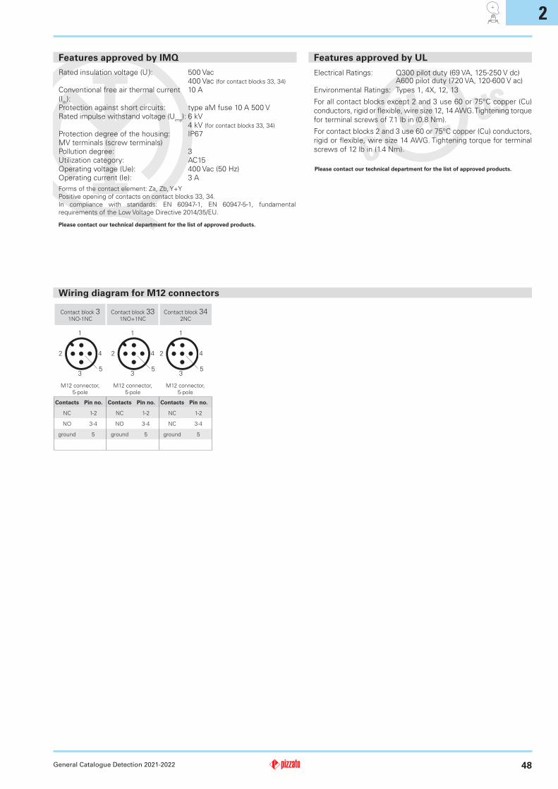
Wiring diagram for M12 connectors
Contact block 31NO-1NC
Contact block 331NO+1NC
Contact block 342NC
M12 connector,
5-pole
M12 connector,
5-pole
M12 connector,
5-pole
Contacts Pin no. Contacts Pin no. Contacts Pin no.
NC 1-2 NC 1-2 NC 1-2
NO 3-4 NO 3-4 NC 3-4
ground 5 ground 5 ground 5
2
49
45.5
7
5.3
14.5
15.2
33.4
30
40
Ø10
17.6
45.5
7
5.3
14.5
15.2
33.4
30
40
44.7
20
25.7 7
45.5
7
5.3
14.5
15.2
33.4
30
40
187 max
Ø6
x200
5.8
41-5
3
5.8
41-5
3
45.5
7
5.3
14.5
15.2
33.4
30
40
42.1
46.1
20 7
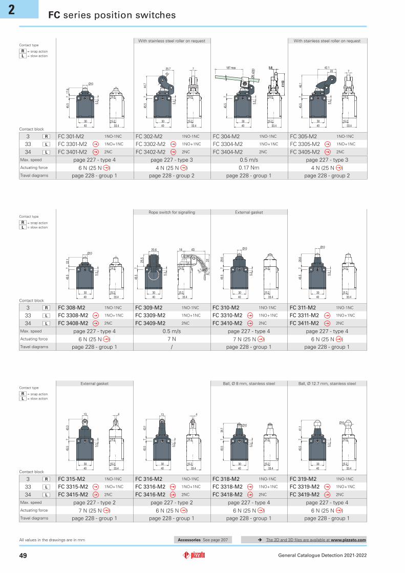
3 R FC 301-M2 1NO-1NC FC 302-M2 1NO-1NC FC 304-M2 1NO-1NC FC 305-M2 1NO-1NC
33 L FC 3301-M2 1NO+1NC FC 3302-M2 1NO+1NC FC 3304-M2 1NO+1NC FC 3305-M2 1NO+1NC
34 L FC 3401-M2 2NC FC 3402-M2 2NC FC 3404-M2 2NC FC 3405-M2 2NC
45.5
7
5.3
14.5
15.2
33.4
30
40
22.1
Ø10
45.5
7
5.3
14.5
15.2
33.4
30
40
25,
5
20,6
5,1
43 14
31
6
45.5
7
5.3
14.5
15.2
33.4
30
40
Ø10
29.6
45.5
7
5.3
14.5
15.2
33.4
30
4029
.8
Ø10
3 R FC 308-M2 1NO-1NC FC 309-M2 1NO-1NC FC 310-M2 1NO-1NC FC 311-M2 1NO-1NC
33 L FC 3308-M2 1NO+1NC FC 3309-M2 1NO+1NC FC 3310-M2 1NO+1NC FC 3311-M2 1NO+1NC
34 L FC 3408-M2 2NC FC 3409-M2 2NC FC 3410-M2 2NC FC 3411-M2 2NC
45.5
7
5.3
14.5
15.2
33.4
30
40
43.3
13 4
45.5
7
5.3
14.5
15.2
33.4
30
40
43.1
13 4
45.5
7
5.3
14.5
15.2
33.4
30
40
34.1
Ø10
45.5
7
5.3
14.5
15.2
33.4
30
40
41.1
Ø16
3 R FC 315-M2 1NO-1NC FC 316-M2 1NO-1NC FC 318-M2 1NO-1NC FC 319-M2 1NO-1NC
33 L FC 3315-M2 1NO+1NC FC 3316-M2 1NO+1NC FC 3318-M2 1NO+1NC FC 3319-M2 1NO+1NC
34 L FC 3415-M2 2NC FC 3416-M2 2NC FC 3418-M2 2NC FC 3419-M2 2NC
General Catalogue Detection 2021-2022
The 2D and 3D files are available at www.pizzato.com
FC series position switches
Accessories See page 207All values in the drawings are in mm
Contact type
R = snap action
L = slow action
Contact type
R = snap action
L = slow action
Contact type
R = snap action
L = slow action
Contact block
Contact block
Contact block
Max. speed page 227 - type 4 page 227 - type 3 0.5 m/s page 227 - type 3
Actuating force 6 N (25 N ) 4 N (25 N ) 0.17 Nm 4 N (25 N )
Travel diagrams page 228 - group 1 page 228 - group 2 page 228 - group 1 page 228 - group 2
Max. speed page 227 - type 4 0.5 m/s page 227 - type 4 page 227 - type 4
Actuating force 6 N (25 N ) 7 N 7 N (25 N ) 6 N (25 N )
Travel diagrams page 228 - group 1 / page 228 - group 1 page 228 - group 1
Max. speed page 227 - type 2 page 227 - type 2 page 227 - type 4 page 227 - type 4
Actuating force 7 N (25 N ) 6 N (25 N ) 6 N (25 N ) 6 N (25 N )
Travel diagrams page 228 - group 1 page 228 - group 1 page 228 - group 1 page 228 - group 1
With stainless steel roller on request With stainless steel roller on request
Rope switch for signalling External gasket
External gasket Ball, Ø 8 mm, stainless steel Ball, Ø 12.7 mm, stainless steel
2
50
45.5
7
5.3
14.5
15.2
33.4
30
40
56.5
12.2
116.
6
45.5
7
5.3
14.5
15.2
33.4
30
40
12.2
131.
1
87
Ø1.2
Ø7.5
12.2
117
45.5
7
5.3
14.5
15.2
33.4
30
40
45.5
7
5.3
14.5
15.2
33.4
30
40
55.1
36.7
7
24
15
55
20
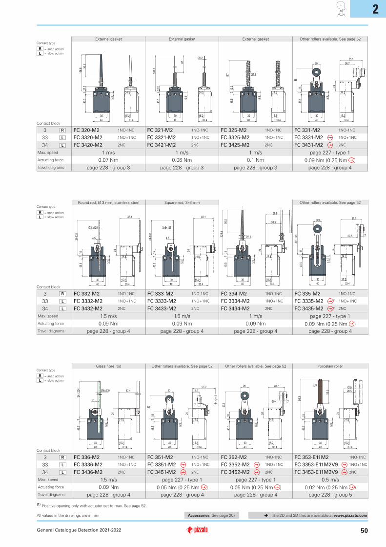
3 R FC 320-M2 1NO-1NC FC 321-M2 1NO-1NC FC 325-M2 1NO-1NC FC 331-M2 1NO-1NC
33 L FC 3320-M2 1NO+1NC FC 3321-M2 1NO+1NC FC 3325-M2 1NO+1NC FC 3331-M2 1NO+1NC
34 L FC 3420-M2 2NC FC 3421-M2 2NC FC 3425-M2 2NC FC 3431-M2 2NC
Ø7.3
56.5
15
124.
538.9
59.9
24
45.5
7
5.3
14.5
15.2
33.4
30
40
45.5
7
5.3
14.5
15.2
33.4
30
40
48.1
24
34-1
31
15
4.5
Ø3 x125
45.5
7
5.3
14.5
15.2
33.4
30
40
48.1
24
34-1
31
15
4.5
3x3x125
45.5
7
5.3
14.5
15.2
33.4
30
40
51.1
40.8
24
Ø20
15
49 -
108 7
3 R FC 332-M2 1NO-1NC FC 333-M2 1NO-1NC FC 334-M2 1NO-1NC FC 335-M2 1NO-1NC
33 L FC 3332-M2 1NO+1NC FC 3333-M2 1NO+1NC FC 3334-M2 1NO+1NC FC 3335-M2 (1) 1NO+1NC
34 L FC 3432-M2 2NC FC 3433-M2 2NC FC 3434-M2 2NC FC 3435-M2 (1) 2NC
45.5
7
5.3
14.5
15.2
33.4
30
40
47.4
24
Ø6x200
10
34 -
204
45.5
7
5.3
14.5
15.2
33.4
30
40
15.9
55.2
7
24
15
20
55
45.5
7
5.3
14.5
15.2
33.4
30
40
30.4
40.7
24
7
15
63.6
20
45.5
7
5.3
14.5
15.2
33.4
30
40
28.5
42.5
24
15
95.3
Ø9
56.5
3 R FC 336-M2 1NO-1NC FC 351-M2 1NO-1NC FC 352-M2 1NO-1NC FC 353-E11M2 1NO-1NC
33 L FC 3336-M2 1NO+1NC FC 3351-M2 1NO+1NC FC 3352-M2 1NO+1NC FC 3353-E11M2V9 1NO+1NC
34 L FC 3436-M2 2NC FC 3451-M2 2NC FC 3452-M2 2NC FC 3453-E11M2V9 2NC
General Catalogue Detection 2021-2022
The 2D and 3D files are available at www.pizzato.com
(1) Positive opening only with actuator set to max. See page 52.
Accessories See page 207All values in the drawings are in mm
Contact type
R = snap action
L = slow action
Contact type
R = snap action
L = slow action
Contact type
R = snap action
L = slow action
Contact block
Contact block
Contact block
Max. speed 1 m/s 1 m/s 1 m/s page 227 - type 1
Actuating force 0.07 Nm 0.06 Nm 0.1 Nm 0.09 Nm (0.25 Nm )
Travel diagrams page 228 - group 3 page 228 - group 3 page 228 - group 3 page 228 - group 4
Max. speed 1.5 m/s 1.5 m/s 1 m/s page 227 - type 1
Actuating force 0.09 Nm 0.09 Nm 0.09 Nm 0.09 Nm (0.25 Nm )
Travel diagrams page 228 - group 4 page 228 - group 4 page 228 - group 4 page 228 - group 4
Max. speed 1.5 m/s page 227 - type 1 page 227 - type 1 0.5 m/s
Actuating force 0.09 Nm 0.05 Nm (0.25 Nm ) 0.05 Nm (0.25 Nm ) 0.02 Nm (0.25 Nm )
Travel diagrams page 228 - group 4 page 228 - group 4 page 228 - group 4 page 228 - group 5
External gasket External gasket External gasket Other rollers available. See page 52
Round rod, Ø 3 mm, stainless steel Square rod, 3x3 mm Other rollers available. See page 52
Glass fibre rod Other rollers available. See page 52 Other rollers available. See page 52 Porcelain roller
2
51
7
2015
M 5
40
24720
M 5
10
49
1
Ø 9
M 5
2.5
80
11.5
57
20
7
M 5
10
34 -
93
1
7
20
43
2011
M 5
VF L51 VF L52 VF L53 (2) VF L56 (3) VF L57
40
20
13.54.9
7
M5
Ø 3x125
4.5
M 5
5
19 -
116
3x3x125
4.5
M 5
5
19 -
116
M 5
2.5
106
55
11.5
20
7
M 5
10
34 -
93
1Ø6x200
10
M 5
6.5
19 -
189
VF L31 VF L32 (3) VF L33 (3) VF L34 VF L35 (1) (3) VF L36 (3)
45.5
7
5.3
14.5
15.2
33.4
30
40
40.8
51.1
24
7
15
49 -
108
20
45.5
7
5.3
14.5
15.2
33.4
30
40
32.5
62.8
24
7
20
15
58
45.5
7
5.3
14.5
15.2
33.4
30
40
14.5
15.3
25.1
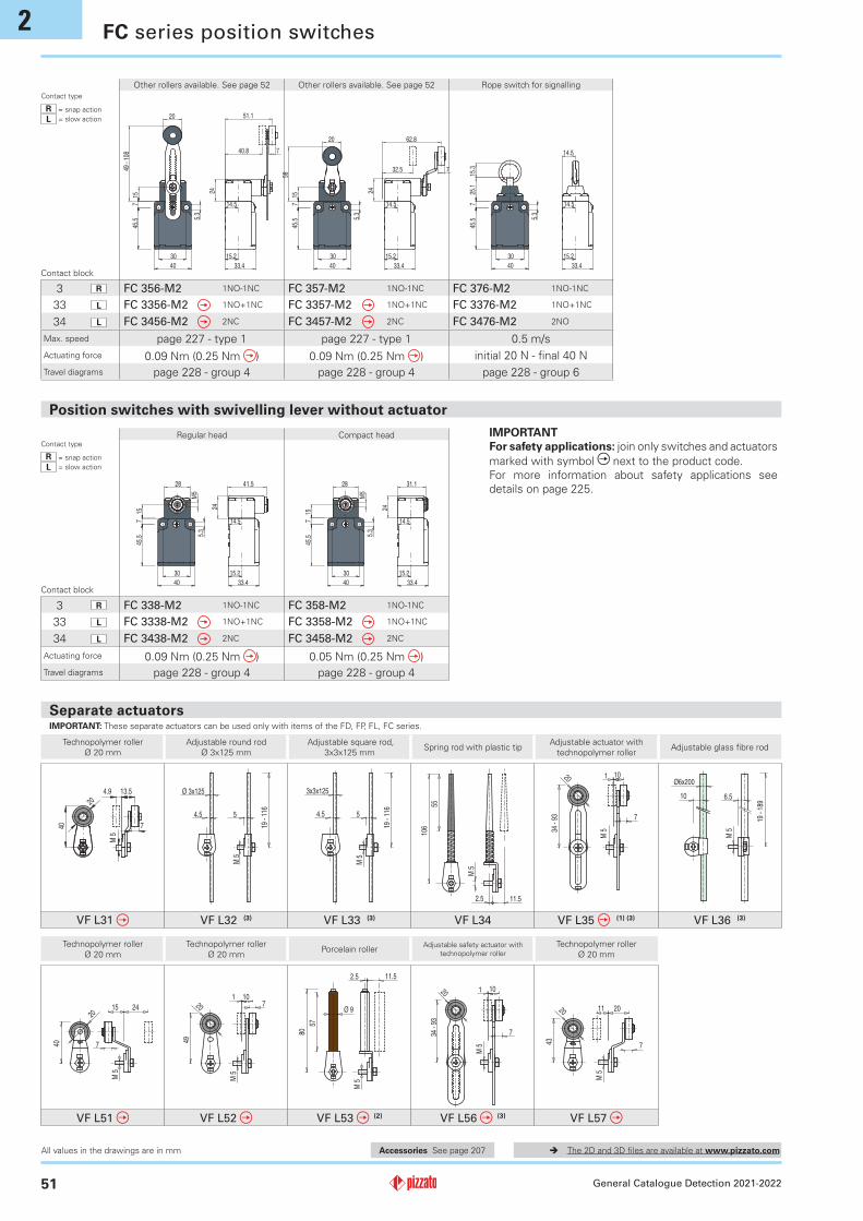
3 R FC 356-M2 1NO-1NC FC 357-M2 1NO-1NC FC 376-M2 1NO-1NC
33 L FC 3356-M2 1NO+1NC FC 3357-M2 1NO+1NC FC 3376-M2 1NO+1NC
34 L FC 3456-M2 2NC FC 3457-M2 2NC FC 3476-M2 2NO
45.5
7
5.3
14.5
15.2
33.4
30
40
41.5
24
M5
28
15
45.5
7
5.3
14.5
15.2
33.4
30
40
31.1
24
M5
28
15
3 R FC 338-M2 1NO-1NC FC 358-M2 1NO-1NC
33 L FC 3338-M2 1NO+1NC FC 3358-M2 1NO+1NC
34 L FC 3438-M2 2NC FC 3458-M2 2NC
General Catalogue Detection 2021-2022
The 2D and 3D files are available at www.pizzato.com
Position switches with swivelling lever without actuator
FC series position switches
Separate actuators
Technopolymer roller
Ø 20 mm
Adjustable round rod
Ø 3x125 mm
Adjustable square rod,
3x3x125 mmSpring rod with plastic tip
Adjustable actuator with
technopolymer rollerAdjustable glass fibre rod
Technopolymer roller
Ø 20 mm
Technopolymer roller
Ø 20 mmPorcelain roller
Adjustable safety actuator with
technopolymer roller
Technopolymer roller
Ø 20 mm
IMPORTANT: These separate actuators can be used only with items of the FD, FP, FL, FC series.
Accessories See page 207
IMPORTANT
For safety applications: join only switches and actuators
marked with symbol next to the product code.
For more information about safety applications see
details on page 225.
All values in the drawings are in mm
Contact type
R = snap action
L = slow action
Contact block
Max. speed page 227 - type 1 page 227 - type 1 0.5 m/s
Actuating force 0.09 Nm (0.25 Nm ) 0.09 Nm (0.25 Nm ) initial 20 N - final 40 N
Travel diagrams page 228 - group 4 page 228 - group 4 page 228 - group 6
Other rollers available. See page 52 Other rollers available. See page 52 Rope switch for signalling
Contact type
R = snap action
L = slow action
Contact block
Regular head Compact head
Actuating force 0.09 Nm (0.25 Nm ) 0.05 Nm (0.25 Nm )
Travel diagrams page 228 - group 4 page 228 - group 4
2
52
93
7
20
M 5
13.5
40
5
20
7
M 5
10
34 -
93
1
7
2015
M 5
40
24 720
M 5
10
49
120
7
M 5
10
34 -
93
1
7
20
43
2011
M 5
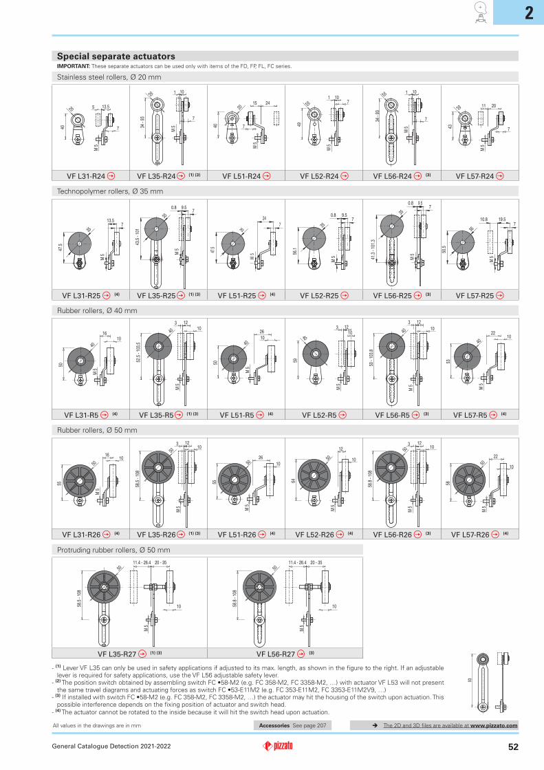
VF L31-R24 VF L35-R24 (1) (3) VF L51-R24 VF L52-R24 VF L56-R24 (3) VF L57-R24
47.5
35
13.5
M5
7
35
43.5
- 1
01
0.8 9.57
M5
35
47.5
24
7
M5
35
56.1
0.8 9.57
M5
35
41.3
- 1
01.3
0.8 9.57
M5
35
50.5
19.510.87
M5
VF L31-R25 (4) VF L35-R25 (1) (3) VF L51-R25 (4) VF L52-R25 VF L56-R25 (3) VF L57-R25
M 5
40
1016
50
M 5
4010
12
52.5
- 1
03.5
3
M 5
10
26
50
40M
510
12
40
59
3
M 5
4010
12
50 -
103
.8
3
M 5
1022
40
53
VF L31-R5 (4) VF L35-R5 (1) (3) VF L51-R5 (4) VF L52-R5 VF L56-R5 (3) VF L57-R5 (4)
5010
M 5
55
1650
10
M 5
58.5
- 1
08
123
M 5
50
55
10
26
M 5
12
1050
64
5010
M 5
58.8
- 1
08
123
M 5
22
50
58
10
VF L31-R26 (4) VF L35-R26 (1) (3) VF L51-R26 (4) VF L52-R26 (4) VF L56-R26 (3) VF L57-R26 (4)
10
50
M 5
20 - 35
58.5
- 1
08
11.4 - 26.4
10
50
M 5
58.8
- 1
08
20 - 3511.4 - 26.4
VF L35-R27 (1) (3) VF L56-R27 (3)
General Catalogue Detection 2021-2022
The 2D and 3D files are available at www.pizzato.com
- (1) Lever VF L35 can only be used in safety applications if adjusted to its max. length, as shown in the figure to the right. If an adjustable lever is required for safety applications, use the VF L56 adjustable safety lever.
- (2)ThepositionswitchobtainedbyassemblingswitchFC•58‑M2(e.g.FC358‑M2,FC3358‑M2,…)withactuatorVFL53willnotpresentthesametraveldiagramsandactuatingforcesasswitchFC•53‑E11M2(e.g.FC353‑E11M2,FC3353‑E11M2V9,…)
- (3)IfinstalledwithswitchFC•58‑M2(e.g.FC358‑M2,FC3358‑M2,…)theactuatormayhitthehousingoftheswitchuponactuation.Thispossible interference depends on the fixing position of actuator and switch head.
- (4) The actuator cannot be rotated to the inside because it will hit the switch head upon actuation.
Stainless steel rollers, Ø 20 mm
Technopolymer rollers, Ø 35 mm
Rubber rollers, Ø 40 mm
Rubber rollers, Ø 50 mm
Protruding rubber rollers, Ø 50 mm
Special separate actuatorsIMPORTANT: These separate actuators can be used only with items of the FD, FP, FL, FC series.
Accessories See page 207All values in the drawings are in mm