Embed Size (px)
Citation preview

3
3 33 34
01-W3 02-W3 05-W3 07-W3 15-W3 30-W3 31-W3 51-W3
20 21 25 34 50 33 69 53
01 08 14 02 A2 A4 05 A5 07
General Catalogue 2015-2016107
Position switches FK series
Selection diagram
1NO-1NC snap action
1NO+1NC, slow action
2NC slow action
Threaded conduit entry
M1 M16x1.5 (standard)PG 11
external rubber gasket
external rubber gasket
external rubber gasket
external rubber gasket
round rod, stainless steel square rod fiber glass rod porcelain roller
product options
accessory sold separately
With cable gland
K24 for cables from Ø 5 to Ø 10 mm
K28 for cables Ø 3…Ø 7 mm
CONDUIT ENTRY
ACTUATORS
CONTACT BLOCKS
WITH RESET

3
FK 302-W3XGM1K24R23T6
52-W3 54-W3 56-W3 57-W3 38-W3
108General Catalogue 2015-2016
Contact blocks
3 1NO-1NC, snap action
33 1NO+1NC, slow action
34 2NC, slow action
Actuators
01 short plunger
02 roller lever
05 angled roller lever
... ........................
Threaded conduit entry
M1 M16x1.5 (standard)PG 11
Reset
without reset (standard)W3 simultaneous resetW4 simultaneous reset, increased force
Housing
FK technopolymer, one conduit entry
External metallic parts
zinc-plated steel (standard)X stainless steel
Code structure Attention! The feasibility of a code number does not mean the effective availability of a product. Please contact our sales office.
LOOSE ACTUATORSSee page 115
A7 15 15-R28 16 10 17 12 13 76
external rubber gasket
roller Ø 11 mm
roller Ø 12 mm,
stainless steel
roller Ø 20 mm
roller Ø 12 mm,
stainless steel
roller Ø 12 mm,
stainless steel
rope switch for signalling
30 31 51 52 54 55 56 57 38
adjustable lever adjustable safety lever without actuator
article options
without actuator
options
Ambient temperature
-25°C … +80°C (standard)T6 -40°C … +80°C
Contact typesilver contacts (stand-ard)
Gsilver contacts with 1 µm gold coating (not for contact block 2)
Pre-installed cable glands
without cable gland (standard)K24 cable gland for cables Ø 5…Ø 10 mmK28 cable gland for cables Ø 3…Ø 7 mm
Please contact our technical service for the complete list of possible combinations.
Rollers
standard roller
R28 stainless steel, Ø 12 mm (for actuators A4, 15)
R23stainless steel, Ø 14 mm (for actuators A2, 02, A5, 05, 30, 31, 51, 52, 54, 55, 56, 57)
R24stainless steel, Ø 20 mm (for actuators 30, 31, 51, 52, 54, 55, 56, 57)
R25technopolymer, Ø 35 mm (for actuators 30, 31, 51, 52, 54, 55, 56, 57)
R5rubber, Ø 40 mm (for actuators 30, 31, 51, 52, 54, 55, 56, 57)
R26rubber, Ø 50 mm (for actuators 51, 52, 54, 55, 56, 57)
R27 rubber, protruding, Ø 50 mm (for actuators 55, 56)

3
Technical data
General Catalogue 2015-2016109
Main features
Technopolymer housing, one conduit entry
Protection degree IP67
3 contact blocks available
46 actuators available
Versions with stainless steel external parts
Versions with gold-plated silver contacts
Electrical data Utilization category
Alternating current: AC15 (50÷60 Hz)Ue (V) 250 400 500Ie (A) 6 4 1Direct current: DC13Ue (V) 24 125 250Ie (A) 6 1.1 0.4
with
out
conn
ecto
r
General dataAmbient temperature: -25°C … +80°CMax. actuation frequency: 3600 operating cycles1/hourMechanical endurance: 20 million operating cycles1
Mounting position: anySafety parameters: B10d: 40,000,00 for NC contactsMechanical interlock, not coded: type 1 according to EN ISO 14119Tightening torques for installation: see pages 235-246(1) One operation cycle means two movements, one to close and one to open contacts, as defined in EN 60947-5-1.
Cable cross section (flexible copper strands)Contact block 33, 34: min. 1 x 0.34 mm2 (1 x AWG 22) max. 2 x 1.5 mm2 (2 x AWG 16)Contact block 3: min. 1 x 0.5 mm2 (1 x AWG 20) max. 2 x 1.5 mm2 (2 x AWG 16)
HousingHousing made of fiber glass reinforced technopolymer, self-extinguishing, shock-proof and with double insulation: One threaded conduit entry: M16x1.5 (standard)Protection degree: IP67 according to EN 60529 with cable gland having equal or higher protection degree
Position switches FK series
Markings and quality marks:
IMQ approval: EG610UL approval: E131787CCC approval: 2007010305230013EAC approval: RUC-ITДМ94.В.01024
Installation for safety applications:Use only switches marked with the symbol aside the product code. Always connect the safety circuit to the NC contacts (normally closed contacts: 11-12, 21-22 or 31-32) as stated in standard EN 60947-5-1, encl. K, par. 2. Actuate the switch at least up to the positive opening travel shown in the travel diagrams on page 240. Operate the switch at least with the positive opening force, indicated between brackets below each article, aside the minimum force value.
In conformity with the requirements of:Low Voltage Directive 2006/95/EC, Machinery Directive 2006/42/EC and EMC Directive 2004/108/EC.Positive contact opening in conformity with standards:IEC 60947-5-1, EN 60947-5-1.
In conformity with standards:IEC 60947-5-1, EN 60947-5-1, EN 60947-1, IEC 60204-1, EN 60204-1, EN ISO 14119, EN ISO 12100, IEC 60529, EN 60529, UL 508, CSA 22.2 No.14 .Approvals:IEC 60947-5-1, UL 508, CSA 22.2 No.14, GB14048.5-2001.
If not expressly indicated in this chapter, for correct installation and utilization of all articles see chapter utilization requirements from page 235 to page 246.
Thermal current (Ith): 10 ARated insulation voltage (Ui): 500 Vac 600 Vdc 400 Vac 500 Vdc (contact blocks 33, 34)Rated impulse withstand voltage (Uimp): 6 kV 4 kV (contact block 33, 34) Conditional short circuit current: 1000 A according to EN 60947-5-1Protection against short circuits: type aM fuse 10 A 500 VPollution degree: 3

3
110General Catalogue 2015-2016
Please contact our technical service for the list of approved products.
Characteristics approved by ULUtilization categories Q300 (69 VA, 125 … 250 Vdc) A600 (720 VA, 120 … 600 Vac)Data of housing type 1, 4X “indoor use only”, 12, 13 For all contact blocks except 2 and 3 use 60 or 75°C copper (Cu) conductor, rigid or flexible, wire size AWG 12/14. Terminal tightening torque of 7.1 lb in (0.8 Nm).For contact blocks 2 and 3 use 60 or 75 °C copper (Cu) conductor, rigid or flexible, wire size AWG 14. Terminal tightening torque of 12 lb in (1.4 Nm).
In conformity with standard: UL 508, CSA 22.2 No.14
Please contact our technical service for the list of approved products.
Characteristics approved by IMQRated insulation voltage (Ui): 500 Vac 400 Vac (for contact blocks 33, 34)Conventional free air thermal current (Ith): 10 AProtection against short circuits: type aM fuse 10 A 500 VRated impulse withstand voltage (Uimp): 6 kV 4 kV (for contact blocks 33, 34)Protection degree of the housing: IP67MV terminals (screw terminals)Pollution degree 3Utilization category: AC15Operating voltage (Ue): 400 Vac (50 Hz)Operating current (Ie): 3 AForms of the contact element: Zb, Y+YPositive opening of contacts on contact blocks 33, 34
In conformity with standards: EN 60947-1, EN 60947-5-1+ A1:2009, fundamental requirements of the Low Voltage Directive 2006/95/EC.

3 R
33 L
34 L
3 R
33 L
34 L
3 R
33 L
34 L
3
321
.4
2022 24.2
36.557
.9
12.2
30.8 30.8
14.2
4.2x
7.2
Ø 8
2022 24.2
36.5
30.8 30.8
14.2
40.1
76.6
12.2
14
3
5.5
4.2x7.2
2022 24.2
36.5
30.8 30.8
14.2
40.1
76.6
12.2
14
3
5.5
4.2x7.2
3
4,2x7,2
30,8
2022
36,5
14,2
30,8
24,2
3167
,5
11
12,2
3,6
2022 24.2
36.5
12.2
30.8 30.8
14.2
340.5
77
14 5.5
12.4
4.2x7.2
2022 24.2
36.5
12.2
30.8 30.8
14.2
340.5
77
14 5.5
12.4
4.2x7.2
30.830.8
3
2022 24.2
12.2
14.2
5.4
22
36.5
5288
.5
4.2x7.2
20(17-23)32(29-35)
30.830.8
3
2022
24.212.2
14.2
5.4
22
36.5
5288
.5
4.2x7.2
20(17-23)32(29-35)
2022 24.2
36.5
12.2
30.8 30.8
14.2
330.1
Ø 10
66.6
4.2x7.2
M12x1
Ø 7.4
30.830.8
5.8
2.514
.2
14
12.272.5
14.2
M 18x1 4
Ø 8
25.2
30.830.8
3
2022 24.2
8.4
36.5
12.285.1
14.2
24
4.2x
7.2
M 18x1 4
3.812
30.830.8
3
2022 24.2
25.2
8.4
36.5
85.1
14.2
12.2
24
4.2x7.2
FK 301-M1 1NO-1NC
FK 3301-M1 1NO+1NC
FK 3401-M1 2NC
FK 3A5-M1 1NO-1NC
FK 33A5-M1 1NO+1NC
FK 34A5-M1 2NC
FK 302-M1 1NO-1NC
FK 3302-M1 1NO+1NC
FK 3402-M1 2NC
FK 3A2-M1 1NO-1NC
FK 33A2-M1 1NO+1NC
FK 34A2-M1 2NC
FK 305-M1 1NO-1NC
FK 3305-M1 1NO+1NC
FK 3405-M1 2NC
FK 307-M1 1NO-1NC
FK 3307-M1 1NO+1NC
FK 3407-M1 2NC
FK 3A7-M1 1NO-1NC
FK 33A7-M1 1NO+1NC
FK 34A7-M1 2NC
FK 310-M1 1NO-1NC
FK 3310-M1 1NO+1NC
FK 3410-M1 2NC
FK 308-M1 1NO-1NC
FK 3308-M1 1NO+1NC
FK 3408-M1 2NC
FK 312-M1 1NO-1NC
FK 3312-M1 1NO+1NC
FK 3412-M1 2NC
FK 313-M1 1NO-1NC
FK 3313-M1 1NO+1NC
FK 3413-M1 2NC
FK 3A4-M1 1NO-1NC
FK 33A4-M1 1NO+1NC
FK 34A4-M1 2NC
Max. speed
Min. force
Travel diagrams
Max. speed
Min. force
Travel diagrams
Max. speed
Min. force
Travel diagrams
General Catalogue 2015-2016111
page 239 - type 34 N (25 N )
page 240 - group 2
page 239 - type 34 N (25 N )
page 240 - group 2
page 239 - type 34.3 N (25 N )
page 240 - group 2
page 239 - type 34.3 N (25 N )
page 240 - group 2
page 239 - type 45 N (25 N )
page 240 - group 1
page 239 - type 34 N (25 N )
page 240 - group 3
page 239 - type 33 N (25 N )
page 240 - group 3
page 239 - type 25 N (25 N )
page 240 - group 1
page 239 - type 45 N (25 N )
page 240 - group 1
page 239 - type 45 N (25 N )
page 240 - group 1
page 239 - type 45 N (25 N )
page 240 - group 1
With external rubber gasket
With stainless steel roller on request
With external rubber gasket
With stainless steel roller on request
With external rubber gasket
With external rubber gasket Fixed only by threaded head in verti-cal position
With stainless steel roller on request
With stainless steel roller on requestContact type:
R = snap actionL = slow action
Contact blocks
Contact blocks
Contact blocks
Position switches FK series
page 239 - type 54.3 N (25 N )
page 240 - group 1
With external rubber gasket
With Ø 12 mm stainless steel roller on request
Accessories See page 225 The 2D/3D files are available at www.pizzato.comAccessories See page 225Accessories See page 225
All measures in the drawings are in mm

3 R
33 L
34 L
3 R
33 L
34 L
3 R
33 L
34 L
3
2022 24.2
36.5
12.2
30.8 30.8
14.2
3R 13
27.9
64.4
4.2x7.2
3.611
30.830.8
3
2022 24.2
3136
.567
.5 12.2
14.2
4.2x
7.2
3.812
30.830.8
3
2022 24.2
31.5
36.5
68 12.2
14.2
4.2x
7.2
2022 24.2
36.5
30.8 30.8
14.2
3
12.2
40.5
77
203.6
4.2x7.2
12
30.830.8
2013 M 12x1
3.8
86
12.2
14.2
3 17
2022 24.2
36.5
12.2
30.8 30.8
14.2
3
124
160.
5
2455
4.2x7.2
Ø 7
20
22 24.2
36.5
12.2
30.8 30.8
14.2
3
Ø 1.2
141
177.
5
24
4.2x7.2
2022 24.2
36.5
12.2
30.8 30.8
14.2
3
Ø 7.5
127
163.
5
24
4.2x7.2
19
30.8
36.5
5490
.5
18
3
2220
16.5
14.2
28
30.8
5.4
24.2
41.5
4.7x7.2
319
4.2x7.2
30.8
202236
.554
90.5
18
14.2
39.4
31.1
28
30.8
24.2
5.4
30.830.8
3
24.2
3x3x125
4.5
1938
- 13
5
28
35
36.5
74.5
- 17
1.5
14.2
2022
30.8
4.2x7.2
55
30.830.8
3
2022
24.2
28
36.5
1912
516
1.5
14.2
4.2x
7.2
27.5
41.5
Ø 7.3
FK 315-M1 1NO-1NC
FK 3315-M1 1NO+1NC
FK 3415-M1 2NC
FK 315-M1R28 1NO-1NC
FK 3315-M1R28 1NO+1NC
FK 3415-M1R28 2NC
FK 316-M1 1NO-1NC
FK 3316-M1 1NO+1NC
FK 3416-M1 2NC
FK 317-M1 1NO-1NC
FK 3317-M1 1NO+1NC
FK 3417-M1 2NC
FK 320-M1 1NO-1NC
FK 3320-M1 1NO+1NC
FK 3420-M1 2NC
FK 321-M1 1NO-1NC
FK 3321-M1 1NO+1NC
FK 3421-M1 2NC
FK 330-M1 1NO-1NC
FK 3330-M1 1NO+1NC
FK 3430-M1 2NC
FK 325-M1 1NO-1NC
FK 3325-M1 1NO+1NC
FK 3425-M1 2NC
FK 331-M1 1NO-1NC
FK 3331-M1 1NO+1NC
FK 3431-M1 2NC
FK 334-M1 1NO-1NC
FK 3334-M1 1NO+1NC
FK 3434-M1 2NC
FK 333-M1 1NO-1NC
FK 3333-M1 1NO+1NC
FK 3433-M1 2NC
FK 314-M1 1NO-1NC
FK 3314-M1 1NO+1NC
FK 3414-M1 2NC
Max. speed
Min. force
Travel diagrams
Max. speed
Min. force
Travel diagrams
Max. speed
Min. force
Travel diagrams
112General Catalogue 2015-2016
page 239 - type 25 N (25 N )
page 240 - group 1
page 239 - type 25 N (25 N )
page 240 - group 1
Roller, Ø 12 mm, stainless steelRoller, Ø 11 mm, technopolymer
page 239 - type 25 N (25 N )
page 240 - group 1
page 239 - type 25 N (25 N )
page 240 - group 1
Fixed only by threaded head in verti-cal position
1 m/s 0.05 Nm
page 240 - group 4
1 m/s 0.05 Nm
page 240 - group 4
page 239 - type 10.05 Nm (0.25 Nm )
page 240 - group 5
1 m/s 0.1 Nm
page 240 - group 4
Square rod, 3x3 mm
page 239 - type 10.05 Nm (0.25 Nm )
page 240 - group 5
1.5 m/s 0.05 Nm
page 240 - group 5
1.5 m/s 0.05 Nm
page 240 - group 5
Other rollers available. See on page 116
Contact blocks
Contact blocks
page 239 - type 46 N (25 N )
page 240 - group 1
With Ø 20 mm stainless steel roller on request
With external rubber gasket With external rubber gasket With external rubber gasket
Accessories See page 225Accessories See page 225Accessories See page 225 The 2D/3D files are available at www.pizzato.com
All measures in the drawings are in mm
Contact type:
R = snap actionL = slow action
Contact blocks
3 R
33 L
34 L
3 R
33 L
34 L
3 R
33 L
34 L
3
30.830.8
3
2022
24.2
19 28
7
20
25
44
5995
.536
.5
14.2
4.2x
7.2
30.8
30.8
3
20
22
24.2
20
53 -
112
28
729
40
36.5
89.5
- 14
8.5
19
14.2
4.2x
7.2
30.830.8
3
20
22
24.2
20
53 -
112
28729
40
36.5
89.5
- 14
8.5
19
14.2
4.2x
7.2 3
2022
24.2
19 28
7
20
19
50
36.5
30.830.8
14.262
98.5
4.2x
7.2
30.830.8
3
24.2
ø3x125
4.5
1938
- 13
5
28
35
36.5
74.5
- 17
1.5
14.2
2022
30.8
4.2x7.2
30.830.8
3
2022
24.2
19 28
36.5
7
5995
.5
14.2
15
54
4.2x
7.2
20
720
30.830.8
3
2022
24.2
19 28
29
40
36.5
14.2
67.6
104.
1
4.2x
7.2
30.830.8
3
2022
24.2
28
36.5
19
Ø 9
56.5
99.3
135.
8
14.2
4.2x
7.2
27.527.5
41.5
30.8
3
22
24.220
28
36.5
36.5
38 -
208
74.5
- 24
4.5
19
14.24.2X
7.2
30.8
Ø6x200
10
3
2022 24.2
36.5
30.8 30.8
14.2
38.8
15.3
93.6
12.2
4.2x7.2
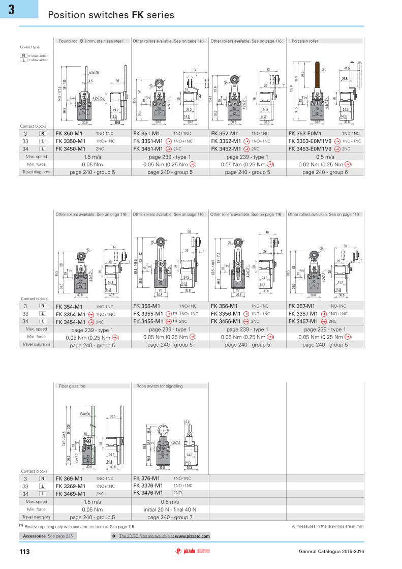
FK 355-M1 1NO-1NC
FK 3355-M1 (1) 1NO+1NC
FK 3455-M1 (1) 2NC
FK 356-M1 1NO-1NC
FK 3356-M1 1NO+1NC
FK 3456-M1 2NC
FK 354-M1 1NO-1NC
FK 3354-M1 1NO+1NC
FK 3454-M1 2NC
FK 353-E0M1 1NO-1NC
FK 3353-E0M1V9 1NO+1NC
FK 3453-E0M1V9 2NC
FK 352-M1 1NO-1NC
FK 3352-M1 1NO+1NC
FK 3452-M1 2NC
FK 351-M1 1NO-1NC
FK 3351-M1 1NO+1NC
FK 3451-M1 2NC
FK 357-M1 1NO-1NC
FK 3357-M1 1NO+1NC
FK 3457-M1 2NC
FK 369-M1 1NO-1NC
FK 3369-M1 1NO+1NC
FK 3469-M1 2NC
FK 376-M1 1NO-1NC
FK 3376-M1 1NO+1NC
FK 3476-M1 2NO
FK 350-M1 1NO-1NC
FK 3350-M1 1NO+1NC
FK 3450-M1 2NC
Max. speed
Min. force
Travel diagrams
Max. speed
Min. force
Travel diagrams
Max. speed
Min. force
Travel diagrams
General Catalogue 2015-2016113
(1) Positive opening only with actuator set to max. See page 115.
Porcelain roller
page 239 - type 10.05 Nm (0.25 Nm )
page 240 - group 5
page 239 - type 10.05 Nm (0.25 Nm )
page 240 - group 5
page 239 - type 10.05 Nm (0.25 Nm )
page 240 - group 5
0.5 m/s0.02 Nm (0.25 Nm )
page 240 - group 6
page 239 - type 10.05 Nm (0.25 Nm )
page 240 - group 5
page 239 - type 10.05 Nm (0.25 Nm )
page 240 - group 5
page 239 - type 10.05 Nm (0.25 Nm )
page 240 - group 5
Fiber glass rod
1.5 m/s0.05 Nm
page 240 - group 5
Rope switch for signalling
Other rollers available. See on page 116 Other rollers available. See on page 116
Other rollers available. See on page 116 Other rollers available. See on page 116 Other rollers available. See on page 116 Other rollers available. See on page 116
0.5 m/sinitial 20 N - final 40 N
page 240 - group 7
Contact blocks
Contact blocks
Position switches FK series
Round rod, Ø 3 mm, stainless steel
1.5 m/s 0.05 Nm
page 240 - group 5
Accessories See page 225Accessories See page 225Accessories See page 225 The 2D/3D files are available at www.pizzato.com
All measures in the drawings are in mm
Contact type:
R = snap actionL = slow action
Contact blocks

33 L
34 L
33 L
34 L
33 L
34 L
3
336
.5
15
34.4
2022
Ø8
70.9
30.8
4.2x7.2
14.2
12.2
30.8
24.245.4
30.8
4.2x7.2
336
.5
2022
53.1
14
89.6 15
14.2
12.2
30.8
24.2
5.5
45.4
353
.536
.590
2022
15
30.8
14
12.4
4.2x7.2
12.2
14.2
5.5
24.245.4
30.8
3
36.5
2022
30.8
22
15101.
565
4.2x7.2
12.2
14.2
24.2
30.8
45.4
5.420(17-23)32(29-35)
336
.5 2022
15
4480
.5
30.8
4.2x7.2
14.2
12.2
30.8
24.2
3.6
45.4
11
2022
6715
32
30.8
36.5
3
18
103.
5
33.2
14.2
42.116.1
41
30.8
24.2
5.4
12.24.2x7.2
3
33.2
15
18
32
6710
3.5
4.2x7.2
5.4
30.8
202236
.5
12.2
14.2
39.4
31.1
41
30.8
24.222
33.2
154.2x7.2
30.83
36.5
32
20
20
7210
8.5
14.2
12.2
15.6
41
54.9
30.8
24.239.5
7
22
15
4.2x7.2
30.8
3
36.5
20
117.
180
.6
33.2
32
20
14.2
12.2
40.4
30.1
41
30.8
24.2
7
22
15
4.2x7.2
30.8
3
36.5
7210
8.5
33.2
32
20
20
14.2
12.2
44.4
26
41
30.8
24.2
7
224.2x7.2
15
30.8
3
36.5
32
20
33.2
66 -
125
102.
5 - 1
61.5
20
14.2
12.2
40.4
30.1
41
30.8
24.2
7
22
15
4.2x7.2
30.8
3
36.5
32
20
33.2
111.
575
20
14.2
12.2
50.4
20.1
41
30.8
24.2
7
FK 3301-W3M1 1NO+1NC
FK 3401-W3M1 2NC
FK 3302-W3M1 1NO+1NC
FK 3402-W3M1 2NC
FK 3305-W3M1 1NO+1NC
FK 3405-W3M1 2NC
FK 3307-W3M1 1NO+1NC
FK 3407-W3M1 2NC
FK 3315-W3M1 1NO+1NC
FK 3415-W3M1 2NC
FK 3330-W3M1 1NO+1NC
FK 3430-W3M1 2NC
FK 3331-W3M1 1NO+1NC
FK 3431-W3M1 2NC
FK 3351-W3M1 1NO+1NC
FK 3451-W3M1 2NC
FK 3354-W3M1 1NO+1NC
FK 3454-W3M1 2NC
FK 3356-W3M1 1NO+1NC
FK 3456-W3M1 2NC
FK 3357-W3M1 1NO+1NC
FK 3457-W3M1 2NC
FK 3352-W3M1 1NO+1NC
FK 3452-W3M1 2NC
Max. speed
Min. force
Travel diagrams
Max. speed
Min. force
Travel diagrams
Max. speed
Min. force
Travel diagrams
114
Pizzato Elettrica has developed a reset device code W3 to make perfectly simultaneous the actuator and the contact block tripping. The new device is a block inserted between the switch body and the head, and could be rotated independently from this last one. This new device has following advantages:• The reset device can be integrated into almost all standard actuator heads• Contact bllocks with snap action are no more necessary because the tripping movement is made by the reset device itself• The reset device can be rotated independently from the head for maximum flexibility during installation• Two driving forces: standard and increased for applications with vibrations• Mechanical endurance: 1 million operating cycles.
General Catalogue 2015-2016
page 239 - type 44.5 N (25 N )
page 241 - group 1
page 239 - type 32.5 N (25 N )
page 241 - group 3
page 239 - type 34 N (25 N )
page 241 - group 2
page 239 - type 34 N (25 N )
page 241 - group 2
page 239 - type 24.5 N (25 N )
page 241 - group 1
page 239 - type 10.07 Nm (0.25 Nm )
page 241 - group 4
page 239 - type 10.07 Nm (0.25 Nm )
page 241 - group 4
page 239 - type 10.07 Nm (0.25 Nm )
page 241 - group 4
page 239 - type 10.07 Nm (0.25 Nm )
page 241 - group 4
page 239 - type 10.07 Nm (0.25 Nm )
page 241 - group 4
page 239 - type 10.07 Nm (0.25 Nm )
page 241 - group 4
page 239 - type 10.07 Nm (0.25 Nm )
page 241 - group 4
With stainless steel roller on requestWith stainless steel roller on request
With Ø 12 mm stainless steel roller on request
Contact blocks
Contact blocks
Other rollers available. See on page 116 Other rollers available. See on page 116 Other rollers available. See on page 116 Other rollers available. See on page 116
Other rollers available. See on page 116Other rollers available. See on page 116With Ø 20 mm stainless steel roller on request
Position switches FK series with reset
Accessories See page 225Accessories See page 225Accessories See page 225 The 2D/3D files are available at www.pizzato.com
All measures in the drawings are in mm
Contact type:
R = snap actionL = slow action
Contact blocks

3 R
33 L
34 L
3
30.830.8
3
2022
24.2
19
30.9
28
36.5
14.2
9
M 4
4.2x
7.2
22
4.2x7.2
15
9
30.8
3
36.5
77.5
32
20
33.2
M4
14.2
12.2
41
30.9
30.8
24.2
93
720
M 4
10
49
1
Ø 9
M 4
2.5
80
11.5
57
7
20
M 4
13.5
40
5
20
7
M 4
10
34 -
93
1 20
7
M 4
10
34 -
93
1
7
20
43
2011
M 4
Ø6x200
10
M 4
6.5
19 -
189
VF LE52 VF LE53 (2) VF LE54 VF LE55 (1) VF LE56 VF LE57 VF LE69
35
1811.25
5.4
M4
18
35
8.30.25.4
M4
3x3x125
4.5
M 4
5
19 -1
16
M 4
2.5
106
55
11.5
Ø 3x125
4.5
M 4
5
19 -
116
7
2015
M 4
40
24
VF LE30 VF LE31 VF LE33 VF LE34 VF LE50 VF LE51
FK 3338-W3M1 1NO+1NC
FK 3438-W3M1 2NC
FK 338-M1 1NO-1NC
FK 3338-M1 1NO+1NC
FK 3438-M1 2NC
Position switches with revolving lever without actuator
Min. force
Travel diagrams
General Catalogue 2015-2016115
IMPORTANTFor safety applications: join only switches and actuators marked with symbol aside the product code.For more information about safety applications see details on page 235.
- (1) Actuator VF LE55 can only be used in safety applications if adjusted to its max. length, as shown in figure beside. If you need an adjustable lever for safety applications, use the adjustable safety lever VF LE56.
- (2) The position switch obtained by assembling switch FK •38‑M1 (e.g. FK 338‑M1, FK 3338‑M1…) with actuator VF LE53 will not present the same travel diagrams and actuating forces as switch FK •53‑E0M1V9 (e.g. FK 353‑E0M1, FK 3353‑E0M1V9…).
- (4) The actuator cannot be rotated to the inside because it will mechanically interfere with the switch head.
0.05 Nm (0.25 Nm )page 240 - group 5
0.07 Nm (0.25 Nm )page 241 - group 4
Position switches FK series
With manual reset knob
Technopolymer roller Ø 20 mm Porcelain roller Technopolymer roller
Ø 20 mmAdjustable actuator with
technopolymer rollerAdjustable safety actuator with technopolymer roller
Technopolymer roller Ø 20 mm Adjustable fiber glass rod
Loose actuatorsIMPORTANT: These loose actuators can be used with items of series FR, FM, FX, FZ and FK only.
Technopolymer roller Ø 18 mm
Technopolymer roller Ø 18 mm
Adjustable square rod, 3x3x125 mm
Flexible rod with pointed end
Adjustable round rod Ø 3x125 mm
Technopolymer roller Ø 20 mm
Increased actuating forceIncreased actuating forceThe switch can be delivered with increased actuating force (option W4). Ideal for applications with vibra-tions.Actuators Min. force01, 14, 15, 16 7 N02, 05 6 N07 3.5 N30 ... 57 0.08 Nm
Accessories See page 225Items with code on green background are stock items Accessories See page 225Items with code on green background are stock items Accessories See page 225Items with code on green background are stock items Accessories See page 225Items with code on green background are stock items The 2D/3D files are available at www.pizzato.com
All measures in the drawings are in mm
All measures in the drawings are in mm
Contact type:
R = snap actionL = slow action
Contact blocks

3
36
209.50.8
7
M4
7
2015
M 4
40
24 720
M 4
10
49
1
7
20
M 4
13.5
40
5
20
7
M 4
10
34 -
93
1 20
7
M 4
10
34 -
93
1
7
20
43
2011
M 4
VF LE31-R24 VF LE51-R24 VF LE52-R24 VF LE54-R24 VF LE55-R24 (1) VF LE56-R24 VF LE57-R24
43.5
35
9.5
M4
735
47.5
247
M4
35
56.1
8 9.57
M4
35
47.5
13.57
M4
35
43.5
- 10
1
0.8 9.57
M4
35
41.3
- 10
1.3
0.8 9.57
M4
35
50.5
19.510.87
M4
VF LE31-R25 (4) VF LE51-R25 (4) VF LE52-R25 VF LE54-R25 (4) VF LE55-R25 (1) VF LE56-R25 VF LE57-R25
46
40
11.510
M4 M 4
1026
50
40
M 4
1012
40
59
3
M 4
4010
16
50
M 4
4010
1252
.5 -
103.
53
M 4
4010
12
50 -
103.
8
3
M 4
10
22
40
53
VF LE31-R5 (4) VF LE51-R5 (4) VF LE52-R5 VF LE54-R5 (4) VF LE55-R5 (1) VF LE56-R5 VF LE57-R5 (4)
M 4
50
55
10
26
M 4
12
1050
64
5010
M 4
55
16
5010
M 4
58.5
- 10
8
12350 10
M 4
58.8
- 10
8
123
M 4
2250
58
10
VF LE51-R26 (4) VF LE52-R26 (4) VF LE54-R26 (4) VF LE55-R26 (1) VF LE56-R26 VF LE57-R26 (4)
10
50
M 4
20 - 35
58.5
- 10
8
11.4 - 26.4
10
50
M 4
58.8
- 10
8
20 - 3511.4 - 26.4
VF LE55-R27 (1) VF LE56-R27
116General Catalogue 2015-2016
Stainless steel rollers, Ø 20 mm
Technopolymer rollers, Ø 35 mm
Rubber rollers, Ø 50 mm
Protruding rubber rollers, Ø 50 mm
Rubber rollers, Ø 40 mm
Special loose actuatorsIMPORTANT: These loose actuators can be used with items of series FR, FM, FX, FZ and FK only.
Accessories See page 225Items with code on green background are stock items Accessories See page 225Items with code on green background are stock items Accessories See page 225Items with code on green background are stock items Accessories See page 225Items with code on green background are stock items The 2D/3D files are available at www.pizzato.com
All measures in the drawings are in mm