Embed Size (px)
Citation preview

MIR PUBLISHERS MOSCOW
FUNDAMENTALSOF MACHINE DESIGN
P. ORLOV
2

11. OPJIOB
H3AATEAbCTBO ((MALIIBHOCTPOEHHE)) M O C K B A

FUNDAMENTALS 2 OF MACHINE DESIGN
P. ORLOV
TRANSLATED FROM THE RUSSIAN by YU. TRAVNICHEV
MIR PUBLISHERS MOSCOW

First Published 1976
The Russian Alphabet and Transliteration
A a Alpha Bf l Beta r y Gamma A ij Delta E e Epsilon Z g Zeta H q Eta 8 0 Theta
The Greek Alphabet
I L Iota K x Kappa A h Lambda M p Mu N v Nu 8 Xi 0 o Omicron 11 n Pi
X x kh q u ts g ¶ ch m sh E(q shch % z "
bI bI y b b ' 3 3 e m10 yu I I R ya
P p Rho Z a Sigma T r Tau r u Upsilon Ocp Phi X X Chi Y $ Psi 51 0 Omega
@ English Translation, Mir Publishers, 1976
Contents
Chapter 1 . Tightened Conneutions . . . . . . . . . . . . . . . . 1.1. Unloaded Connections . . . . . . . . . . . . . . . . 1.2. Loaded Connections . . . . . . . . . . . . . . . . .
Chapter 2 . 2.1. 2.2. 2.3. 2.4. 2.5. 2.6. 2.7. 2.8. 2.9. 2.10. 2.11.
Press-Fitted Connections . . . . . . . . . . . . . . Press (Drive) Fits . . . . . . . . . . . . . . . . . Strength of PressFitted Connections . . . . . . . . . Selection of Fits . . . . . . . . . . . . . . . . . . Calculation Diagrams . . . . . . . . . . . . . . . . Probability Calculations for Press-Fitted Connections . Press-Fitting with Heating or Cooling of Parts . . . . . Pressed Connections with Electrodeposited Coatings . . Design of Pressed Connections . . . . . . . . . . . . Conical Fits . . . . . . . . . . . . . . . . . . . . Serrated Connections . . . . . . . . . . . . . . . . Glued Connections . . . . . . . . . . . . . . . . .
Chapter 3 . Centring Connections . . . . . . . . . . . . . . . . 3.1. Design Rules . . . . . . . . . . . . . . . . . . .
Chapter 4 . Screwed Connections . . . . . . . . . . . . . 4.1. Longitudinal and Transverse Location of Parts in Screwed
. . . . . . . . . . . . . . . . . . . . Connections 4.2. Centring in Screwed Connections . . . . . . . . . . . 4.3. Design Rules . . . . . . . . . . . . . . . . . . . . 4.4. Reinforcement of Fastening Joints . . . . . . . . .
Chapter 5 . 5.1. 5.2. 5.3. 5.4. 5.5.
Chapter 6 .
Flanged Connections . . . . . . . . . . . . . . . . Alignment of Flanges . . . . . . . . . . . . . . .
. . . . . . Machining the End Faces df Fastening Holes Diameter and Spacing of Bolts . . . . . . . . . . . . Three-Flange Joints . . . . . . . . . . . . . . . . . Conical Flange Joints . . . . . . . . . . . . . . . . General Principles which Should Be Followed when Desig- ning Units and Parts . . . . . . . . . . . . . . . .
. . . . . . . . . . . Unification of Design Elements Unification of Parts . . . . . . . . . . . . . . . . Principle of Unitization . . . . . . . . . . . . . . . Elimination of Adjustments . . . . . . . . . . . . . Rationalization of Power Schemes . . . . . . . . . . .
. . . . . . . . . . . . . . . . . . . . Compensators Torsion Bars . . . . . . . . . . . . . . . . . . . . Floating Cross-Sliding Couplings . . . . . . . . . . .

6 Contents
6.9. Elimination and Reduction of Bending . . . . . . . . 6.10. Elimination of Deformation Due to Tightening . . . . .
. . . . . . . . . . . . . . . . . 6.11. Design Compactness . . . . . . . . . . . . . 6.12. Combining Design Functions
. . . . . . . . . . . . . . . . . . . . 6.13. Equistrength . . . . . . . . . . . . 6.14. Uniform Loading of Supports
. . . . . . . . . . . . . . 6.15. Self-Alignment Principle 6.16. Cambering . . . . . . . . . . . . . . . . . . . . . 6.17. Effect of Elasticity upon Load Distribution . . . . . .
. . . . . . . . . . . . . 6.18. Fitting to Several Surfaces . . . . . . . . . . . . 6.19. Tightening Up on Two Surfaces . . . . . . . . . . . . . . . . 6.20. Axial Fixing of Parts . . . . . . . . . . . . . . . . 6.21. Control of Direction
. . . . . . . . . . . . . . . . . 6.22. Mounting Surfaces 6.23. Butt-Jointing on Intersecting Surfaces . . . . . . . . 6.24. Interchangeability of Rapidly Wearing Parts . . . . . 6.25. Accuracy of the Alignment of Parts . . . . . . . . . 6.26. Relief of Precision Mechanisms . . . . . . . . . . 6.27. Coupling Parts Made from Hard an> Soft Materials . . . 6.28. Elimination of Local Weak Spots . . . . . . . . . . . 6.29. Strengthening of Deformable Areas . . . . . . . . . . 6.30. Composite Constructions . . . . . . . . . . . . . .
. . . . . . . . . . . . . . . . . . . . . . 6.31. Shoulders 6.32. Chamfers and Fillets . . . . . . . . . . . . . . . .

Chapter 1
Tightened Connections
Depending on their operating conditions tightened connections can be divided into unloaded and loaded ones.
1.1. Unloaded Connections
These include joints of non-bearing covers, non-bearing housing components, etc. I n this case the necessary bolt (or stud) tightening force is determined proceeding from the condition that the joint should remain tight and unparted with all possible deformations in the system and with possible slacking of the screwed connections as a result of the threads or the supporting surfaces of the nut and bolt being crushed in the course of time. If the loads arising in the system during operation are not considered, then the bolt load is only the force of preliminary tightening (preload).
Such connections in the majority of cases are not calculated. The material, diameter and thread pitch of bolts are selected on the basis of existing practice, and the tightening force is set so that the stresses developing in the bolt correspond to a 3- 5-fold safety margin (in terms of the yield strength) as usual.
In non-critical connections the tightening force is not specified, but left to the fitter to decide upon by his experience. I n mechanized assembly shops such joints are tightened mechanically with the aid of electric or pneumatic torque-control bolt drivers and nut runners.
The tightening torque Mt igh t , which is equal to the product of the force applied to the wrench end and the wrench arm, produces axial force Pax (Fig. 1) stretching the bolt and overcomes the moment of friction in the threads and on the nut bearing surface
Pax tan vdo Paxdo M ~ g h t = ( 2 + f i 7 +- f 2 v) kgf am
where P a x = axial force arising as a result of the bolt tightening, kgf
do = pitch diameter of the thread, mm D = mean diameter of nut bearing surface, mm

8 Chapter I . Tightened Connections
f , and f, = coefficient of friction in the threads and on the nut bearing surface, respectively
cP = thread helix angle S
Introducing tan rp = - (where s is the thread pitch) gives ndo
where d is the nominal diameter of the thread, mm. For the current diameter ranges of fastening bolts it is usual to
take on the average s/d = 0.15; d,ld = 0.9; and Dld = 1.3. Substituting these values into Eq. (1.2), we get
Mtight = 10-3PaXd (0.024 + 0.45fi + +0.65f2) kgf-m
whence Mtisht
P a x = d (0.021+0.45j1+0.65j2)
(1.3)
Let f, = 0.22 and f 2 = 0.11. Then
5fiItight pax = 103 ;i-- (1.4)
Force Pax induces tensile stresses
Fig. 1. Determination of bolt in the bolt tightening torque Pax Of ens =
where d, is the minor diameter of the thread (for light bolts - the diameter of the bolt stem), mm.
Pasdo The moment of friction in the threads f, causes torsional
stresses in the bolt
where Wt,,, = 0.2d: is the torsion resisting moment of the bolt cross-section.
Consequently
The total stress, according to the third theory of strength, is

1.1. Unloaded Connections 9
Assuming (on the average) that dl = 0 .8d , and substituting the values f, = 0.22 and d , / d = 0 .9 , we obtain
Substituting into this expression the value of Pa, from Eq. (1.4), we have
where Mtight = tightening torque, kgf am d = nominal diameter of the thread, mm
The values of o versus Mtight , shown in Fig. 2, are estimated from Eq. (1.7) for bolts of different diameters. The diagram can be used'
Fig. 2. Tightening torque Mtight and stresses o for bolts of different diameters
for approximate determination of stresses developing in a bolt- tightened with various torques. From the permissible stress i t i s possible to find the ultimate tightening torque.

10 Chapter I . Tightened Connections
The inverse-cube relationship between the stresses due to tighten- ing and bolt diameter [see Eq. (1.7)l accounts for the abrupt rise of the stresses, occurring when the bolt diameter is reduced. When manually tightening small-diameter bolts, one may overstress the bolts, thus stretching and even breaking them.
Approximate values of forces and torques when tightening bolts b y hand are given in Table 1.
Table 1
Forces and Torques when Tightening Bolts Manually
Assume, for example, that the tightening torque is 1.5 kgf -m. Drawing in Fig. 2 a horizontal line M t i g h t = 1.5 kgf-m, we read the stress values on the abscissa axis: for bolts M8-37 kgf/mm2; for bolts M6-80 kgf/mm2. The latter figure is well above the yield l imit of commercial carbon steels. Consequently, bolts smaller than M6 may easily be broken when tightened by hand, and with the application of excessive forces bolts M8 may also be broken.
The magnitude of stresses due to tightening, in accordance with E q . (1.3), strongly depends on the coefficient of friction in the threads -and on the nut bearing surface. Friction blocks, as i t were, the tighten- ing force, so that a major part of the latter is spent in overcoming friction, only an insignificant portion being taken up by the bolt stem.
For example, when f, = 0.22 and f, = 0.11 the portion of the torque utilized for the bolt tightening, according to Eq. (1.3), will be
The remaining 88% of the torque is spent in overcoming friction. Equation (1.7) and the diagram in Fig. 2 are based on rather high
values of the friction coefficients Cfl = 0.22; f, = 0.11) correspond- i n g to non-lubricated surfaces. If some lubricant gets onto the friction surfaces, then, with the same torque, the bolt stresses will rise.
Table 2 gives the values of stresses, calculated from Eq. (1.7), which arise in bolts tightened by means of standard wrenches with t h e application of 15-kgf tightening force. From the Table it is clear that with low friction values it is possible to break even MI0 bolts when tightening them manually. The possibility of overstres-
Bolts Tightening force, kgt
w 10 w 15 w 20
.Small (M4-M8) Medium (M10-M14) Large (M 16-M24)
Tightening torque, kgf -m
1-1.5 2-3 4-5
0.1-0.15 0.15-0.2 0.2-0.25

2.2. Unloaded Connections 11
a Table 2 Stresses in Bolts when Tightening with Standard Wrenches
Note. The heavy line delimits stresses exceeding the yield limit of commercial carbon steels.
sing bolts with threads larger than MI2 when tightening them with standard wrenches is practically excluded.
If, however, small-sized bolts must be used for some design reasons, then appropriate measures must be taken to limit the tightening
Bolt dia.
M6 M8
M 10
M 12 MI4 MI6
Fig. 3. Methods of eliminating bolt twist when tightening
torque or the bolts must be made from a high-grade heat-treated steel.
The simplest way to limit the tightening torque is to shorten the wrench arm correspondingly with the decrease of the bolt diameter. This practice is, in effect, stipulated by current standards covering 'wrenches and spanners.
Stresses in kgf/mma when
f i = 0.22 fz= 0.11
f i = 0.1 1 fz = 0.055
100 50
30
17 12 22 9 16

12 Chapter I . Tightened Connections
The twisting-off of a bolt can be avoided if during tightening i t is held by a special element (Fig. 3a) or if the bolt end is locked t o the housing (Fig. 3b). I n these cases only tensile stresses occur in the bolt.
Assume that in Eq. (1.5) T = 0, and dl = 0.8d (as before), then
Comparing this expression with Eq. (1.6), we see that the stresses 1.56 - amount only to m- 0.65 of the stresses when tightening a bolt
with its being twisted. Torsional stresses arise only during tightening and subsequently
vanish due to the bolt elasticity. Therefore, when designing tightened connections for long-term strength the torsional stresses are usually neglected, the bolt calculations being limited to the axial force P,, only [see Eq. (1.3)l.
1.2. Loaded Co~ections
These include connections subjected to the action of a force which stretches the joint and imposes an additional load upon the fastening bolts. This force can be constant (e.g., the static pressure of gases and liquids in vessels) or variable (the pressure of gases in internal
combustion engines and piston compressors, inertia forces of moving masses in connecting rods and bearings of crank mechanisms).
Here the >bolt preload is selected so that, regardless of possible working force fluctua- tions, a constant tension a t the joint is maintained, avert- ing i ts opening which could break the joint seal and, in the
Fig. 4. Tightened connection case of variable forces, cause the crushing and work hard- ening of the metal surfaces.
The connection may be additionally loaded by thermal forces aris- ing as the system gets heated.
Figure 4 shows a bolted connection subjected to the action of internal working pressure Pwork . To assure normal functioning of the joint the bolts must be pretightened by a force P t i p h t sufficient to keep the joint tight under the action of working force Pwork.
Now let us clarify what deformations occur in the system when force Pti , , , is applied to it. For the sake of simplicity we neglect changes

1.2. Loaded Connections 13
in the length of the threaded bolt ends and consider that the working length I of the bolts is equal to the thickness of the joined parts.
Under the action of force P t i g h t the bolts will lengthen by the value
while the joined flanges will shrink by the value Ptight l
h2= - E2F2
where El, E , and Fl, F , are the elasticity moduli of the materials and cross-sectional areas of the bolts and housing, respectively.
The force with which the housing members are compressed is equal to the tightening force, i.e.,
P c o m p = P t i g h t ( I 4 After the application of the working force Pwork the bolts will
additionally extend by the value Ah, and, accordingly, the housing compressive deformation will decrease by the same value. As a result, the pressure exerted by the housing upon the bolts is reduced by the amount AP.
The force tensioning the bolts becomes
P t e n s = PWOrk f P t i g h t - AP (I .9) and the force of the housing compression
P e o m p = P t i g h t - AP (1 .lo)
Force AP can be deduced from the following relationships. In accord with Hooke's law, the value of the housing deformation
decrease is API Ah=-
EzF2
In bolts the same amount of deformation is produced by the dif- ference of forces prior to and after the application of force Pwork , i.e.,
P t e n s - P t i g h t = P w o r k f P t i g h f - AP- P t i g h t = P w o r k - A P
Consequently, in respect to the bolts
Equating Eqs. (1.11) and (1.12), gives

14 Chapter I. Tightened Connections
Substituting this expression into Eqs. (1.9) and (1.10) gives the bolt tension force
Pwork Pwork Piens = P w o r k f Pt igh t - EiFi = Pt ight + E ~ F ~ (1.14)
I+- EzF2
i+- EiFt
and the joint compression force Pwork
P c o m p = Pt ight -
If the working force varies from zero up to Pwork , then the bolt tension force will pulsate with an amplitude
Pwork Atens = Ptens - P t i g h t = E2F2
(1.16) 1+-
EiFi while the housing compression force will pulsate with an amplitude
Pwork Acornp = P t i g h t - P c o m p - E~~~ (1.17)
1-k- E2F2
Length does not enter into Eqs. (1.14)-(1.17). This means that the forces acting a t the joint are theoretically equal when tightening low flanges and high housing components by bolts.
Actually the forces under consideration are affected by the elastic and plastic deformations of the threads and bearing surfaces of the nuts and bolt heads, etc., which may appreciably reduce the forces that tension the 1)olts and compress the connection.
The relative significance of terminal conditions is much greater for shorter bolts than for longer ones. That is why the joints fastened with short bolts weaken more quickly in use, particularly when sub- jected to pulsating loads. As a general rule, i t is better to use long bolts (high flanges) or introduce elastic elements compensating for local plastic deformations of the system.
On the basis of Eqs. (1.14) and (1.15) i t is often concluded that smaller ratios E1FlIE2F2 are more beneficial, in other words, the best combination is elastic bolts and rigid housings.
From Eq. (1.14) i t is evident that the bolt tension force is minimum E f Fi (Ptens = Piight) when - = 0 (perfectly elastic bolts or perfectly EzFz - -
h'tf"i rigid housings) and increases with an increase in - reaching EzFz ' - -
its maximum (Pi.,, = Ptighi + Pwork) when 3 = ca (per- EzF2 fectly elastic housings or perfectly rigid bolts). The amplitude of the pulsating tension force [Eq. (1.16)l also falls down with a decrease in 'A. In the limiting case (g = 0) the bolt tension force
EzFz
1.2. Loaded Connections 1'5
remains constant and is Ptens = Pt igh t , i.e., the load on the bolts becomes static despite the pulsating working force: With-an increase
E i F i the load on the bolts becomes cyclic. &hen = co in - EzF2 E2F2
the pulsation amplitude is Atens = Pwork. With a decrease in - EiFi the joint compression force PC.,,
EzFz [Eq. (1.15)l is also reduced. This is beneficial for the housing strength, but is disadvantageous for the joint sealing, since the force sealing the split connection is equal to PC,,,. At the same time, with the
the pulsation of force PC,,, [Eq. (1.17)l is increas- decrease of - K2F2
ed, but since the housing strength is usually much greater than the bolt strength and the compression force fluctuations are not so. dangerous as the bolt tension force fluctuations, then i t is recommend- -
E i F i values, as it is considered that this lowers ed to employ low -a-
the bolt load. From this stems the time-honoured design rule for split connections: elastic bolts-rigid flanges.
To this rule certain essential corrections are necessary. To fully reveal the essence of this phenomenon, it is necessary t o
ascribe definiteness to the member Ptight entering into Eqs. (1.14) and (1.15), i.e., to agree upon how to select the tightening force. There are two methods of such a selection. I n accord with the first method, widely applied until recently, the tightening force was taken in proportion to the working force Pwork
P t i g h t = ~ P w o r k (1.18) where y is the tightening factor (usually y = 1-2).
According to the second method, the tightening force is found on condition that the joint compression force PC,,, is proportional to the working force, i.e.,
Pcornp = 0Pwork (1.19)' where 0 is the proportionality factor (generally 0 = 0.25-1).
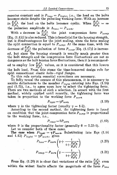
Let us consider both of these cases. The case when Ptight = yPzooTlc. Substituting into Eqs (1.14
and 1.15) Ptight = yPwork, gives
1 (1.21)
EiFi From E q . (1.20) it is clear that variations of the ratio - even EzF2
within the widest limits affects the magnitude of the force Pten,

16 Chapter I . Tightened Connections
comparatively little. In the limiting cases Piens = PmOrky (when EiFi - EA = 0) and Pien. = Pworr ( I + y) (when - - m) . Hence,
EzF2 E2Fz I + Y . -the entire range of force Ptens is confined within the limits -
Y the number of I t should be noted that in the expression -
EzF2 possible values of the ratio EI/E2 is limited. Bolts are made almost
& Pwork
2.4
2
1.6
12
0 0.2 0.4 0.6 0 .aF7 / f2 0 0.2 0.4 0.6 0 . 8 F f / f 2
Fig. 5. Ratios Ptens/Pwork and Pcomp/~work as a function of Fl/F2 for diffe- rent values of tightening factor y
exclusively of steels (E = 20.103- 22 .lo3 kgf/mm2) and in very rare cases (in special constructions) - of titanium alloys (E = = 11.5 .lo3-12.5 . lo3 kgf/mm2).
Joined members are made of steels, cast irons, light and titanium alloys (Table 3).
There are three vahes of the ratio ElIE2 having practical impor- tance: ElIE2 = 1 (steel-steel; titanium alloy-titanium alloy);E1/E2w NN 2.5 (steel-cast iron); EIIE, w 3 (steel-aluminium alloys).
value can be influenced only With specified materials the by changing the ratio Fl/F2, whilh-entails changes in the strength of the bolts and housings.
When clamping a split aluminium housing with steel bolts (ElIE2 w 3) the ratio Ptens/PwoTk, for different values of y taken in a wide range of FlIF2 values (from zero to unity), will vary inap- preciably, only by 1.5-2 times on the average, as evident from Fig. 5a.

1.2. Loaded Connections 17
Table 3 Material Combinations for Bolts and Joined Components
Thus, the gain from decreasing FIIF, is not very great. The picture is similar for other ElIE2 ratios.
Decreasing the force Prens still does not mean an improvement in the bolt strength which is determined by the stress o = b~
Fi Such an improvement will only be reached if the ratio F11F2. is reduced by increasing the housing cross-section and not by reducing the bolt cross-sections. It can easily be proved that reducing the bolt cross-sections decreases relatively little the force Ptens, and, a t the same time, sharply increases the bolt stresses.
On the other hand, increasing the ratio FlIF, by enlarging the bolt cross-sections provides a definite gain in the bolt strength.
In relation to joints for which good sealing is imperative i t is extremely important to find how the compression force PC,,, changes with F11F2, for this force determines the tightening of the joint seal.
The values of the ratio P,o,,IP,o,k (for ElIE2 = 3), estimated from Eq. (1.21), are plotted in Fig. 5b. The compression force decreas- es with the reduction of the ratio FIIF, (rigid housings), the decrease being the sharper the less the value of y. For example, with y = 1.25 force PC,,, within the range of FlIF2 of from 0 to 1 is reducedfour times. Hence, the decrease of the ratio FlIF2 adversely affects the reliability of the joint.
To assure reliable sealing in the case of rigid housings it is neces- sary to increase the tightening force, i.e., to increase the bolt tension, which makes the gain from lowering FlIF2 fictive.
Conversely, making the housing more pliable lowers the necessary tightening force. With compliant housings it is possible to tighten
EiIE2
1 2.6 2.9 4.7 1.75
1
~ o l t material
Steel Ei = 21 000 kgflmm2
Titanium alloy Ei = 12 000 kgflrnmz
Joined components
material I E2. *@/mma
Steel Cast iron Aluminium alloys Magnesium alloys Titanium alloys
Titanium alloys
21 000 8000 7200 4 500
12 000
12 000

18 Chanter 1. Tightened Connections
the joint with y < 1 without running the risk of the joint loosening (Pc,mpIPwo,k > 0) and without impairing i t s reliability.
Let us now examine the effect of the ratio FIIF,upon the pulsation amplitude of forces Pt,,, and PC,,, (Fig. 6). I t is evident from the graph that decreasing the ratio FIIF2 (rigid housings) lowers the pulsation amplitude of force Pt,,,, which is advatageous for the bolt strength. However, the pulsation of force PC,,, increases as the ratio F11F2 is reduced, this adversely affecting the reliability of the joint.
Thus, we may conclude that with P t i r h t = yPwork, low ratios FIIF, (rigid housings) are advantageous for the bolt strength when
Fig. 6. Ratios Ate,,JPwoTr and Aeomfior l as a function of Fi]P2 for diffe- rent values of lghtenlng factor y
the loads on the joint are pulsating. For static (in particular thermal) loads, and also when the reliability of the joint is of prime importan- ce, higher ratios F11F2 (compliant housings) are preferable.
The foregoing conclusions are of special significance for connect- ions in which the rigidity of the joined parts is commensurable with that of the clamping bolts. Such a situation is encountered, for instance, when clamping hydraulic and air power cylinders (Fig. 7a) and cylinders of internal combustion engines and piston compressors of half-block (Fig. 7b) or full-block (Fig. 7c) designs. Here the design- er can vary within broad limits the ratio F11F2 by changing the cross-sections of the clamped components and thus make it most suitable for the given operating conditions.
With conventional flange connections manoeuvring possibilities are less. As shown by experiments, actually in operation is the cylin-

drical flange volume of external diameter D w 2d, and internal diameter d M do (Fig. 8a). The ratio of. the bolt crass-sectioaal
Fig. 7. Tightened connections
area to the design area of the clamped parts is
This ratio can be increased by placing an elastic gasket between the parts being connected, or reduced by placing under the bolt some massive washers of increased diameterland a b o by decreasing the bolt stem diameter (Fig. 8b) .
Assuming that Dl = 3 4 and d, = 0.8do, we have
F (0.8do)2 - = 0 . 0 8 F2 D:-dt
The ratio F1/F, can also be reduced by placing ela- stic elements between the flange and bolt faces.
The case when PC,, = = O P , , , k . The relationships become different when the (a) tightening force is chosen Fig. 8. Tightened flanges so that P,,,, of the joint is proportional to Pwork. This condition is quite logical: the highed the working pressure, the greater must be the compression to enstire the required reliability of the' joint. Selecting the'tightening force in such a way establishes a direct relation between the joint con67

e(, Chapter 1. Ttghtened Connections
I)rmion force and the working force, whereas in the previous case $hi8 mlation is a derivative of the preliminarily chosen tightening factor y and of elasticity characteristics of the system.
Thelbolt tension force is always equal to the sum of the working and compression forces. Hence,
Ptens = PWOrk + Pcomp = (1 + 0 ) Pwork (1.22) Tbus, the forces Ptens and PC,,, (for a given force Pwork) in this
case are constant and independent of the ratio E1F11E2F2. From Eq. (1.15) the required tightening force
Pwork Ptight = Pc0.p + EiFi (1.23) i+-
E2F2 Substituting into this relation the value PC,,, = 8PWork, we get
Ptight = P W O ~ (" 'Pi ) (1.24) I+m
The ratio Pt igh t /Pwork as a function of FlIF2 (when ElIE2 = 3) is plotted for various values of 8 in Fig. 9. The graph shows that
4ight increasing the ratio FlIF2
pwork (compliant housings) redu- ces the required tightening force.
The determination of the tightening force on condi- tion that PC,,, = 8PWork is undoubtedly more ration- a l than on condition that Pt igh t = ?Pwork. The lat- ter method must be reject- ed as being wrong in prin- ciple. I n this connection the problem of the influen- ce of the E1F11E2F2 factor on the operation of the jo- int should be reconsidered.
Asis obvious from the fore- 0.2 0.4 0.6 0.8 / going, when Pcomp=8Pwork
Fig. 9. Ratio Ptight/Pwork as a function of the ratio ElFlIE2F2 has no FlIF2 for different values of factor 0 influence on the forces Pt,,,
and PC,,, which are de- fined exclusively by the magnitude of factor 8 . The ratio E1F11E2F, affects the tightening force only. Higher
values of E1F,IE2F, (compliant housings) are more advantageous as they enable the required tightening force to be decreased.

1.2. Loaded Connections 21
In connections loaded by a pulsating form the ratio EIFIIE,F, also affects the pulsation amplitude of forces Ptens and According to Eqs. (1.16) and (1.17), as ElFlIE,F2 decreases (rigid housings), the pulsation amplitude of Pten, is reduced, while that of PC,,,, increased.' Conversely, increasing ElF11E2F2 (compliant housings) augments the pulsation amplitude of Pten, and diminishes that of PC,,,. Consequently, we may conclude that under pulsating loads rigid housings are more advantageous for the bolt strength and compliant housings, for reliable sealing.
In joints loaded by a constant force the magnitude of EIF1!E,F seems indifferent both for the bolt strength and for the quality of sealing. All the above considerations on the relative advantages of rigid and compliant housings under a static load are valid only when Plight = yPwork and lose their value when PC,,, = BPwork.
The magnitude of factor 9, which in the given case is of decisive importance for the joint parameters, is chosen ta suit the reliability requirements for the seal: for non-critical joints 8 = 0.25 to 0.3 and for critical joints, 0.5 to 1.
The calculation on condition that PC,,, = 8Pwork is simpler. There is no need for the cut-and-try procedure of finding Ptight and checking the resulting PComp, and the calculation comes to the application of the simplest formulae (1.22), (1.23) and (1.24) which a t once yield all the values determining the strength and reliability of the joint.
(a) Temperature Factors
If a joint operates a t elevated temperatures, and the temperatures of the clamping bolts and joined parts differ, or if the parts are made of materials possessing different coefficients of linear expansion, a thermal stress Pt then develops in the joint. I n accord with Eq. (7.1) [see Fundamentals of Machine Design, Vol. 1, Chapter 71, this stress is
where a,, a2 = coefficients of linear expansion of the materials of the bolts and housing, respectively
t,, t, = working temperatures of the bolts and housing The total bolt tension force is equal t o the sum of forces Ptens
and Pt

E2 Chapter 1. Tightened Connections
The total joint compression force is equal to the sum of forces PC,, and Pt
Pwork (%t2 - a i t i ) EiFt P-p= Pcomp +P, t= Ptight - EiFi + EiF1 (1.27) I + -
E2F2 I + =
( b ) Housings with Changing Sections
Often met in practice are cases when the parts being clamped have changing (variable) sections (Fig. 10a) or are made of materials with different moduli of elasticity.
Fig. 10. Complex systems (a) with elements Of changing section; ( b ) with elastic element8
Let l', I " , I"', . . . be the lengths of the dissimilar sections (1' + + 1" + lm, . . . = I ) and let each have i ts corresponding rigidity factor E'F', E1'F", EmF"', . . . .
Then the rigidity factor E,F, in the previous expressions should be changed to a corrected factor whose magnitude is determined from the following considerations.
Let a complex system be acted upon by a force P . The total defor- mation A of the system, produced by the force, will be the sum of the deformations of i ts individual elements
PI' h=hl+h"+. . . =- PI" Et,, +m+ .

1.2. Loaded Connections 23
The relative deformation of the system
The corrected rigidity factor of the system
Introducing this factor into the previous equations in place of E,F,, the calculation can be carried out as previously.
In this case the temperature deformation is
where a, = coefficient of linear expansion of the bolt material t, = bolt temperature
In relative units
The sum of the deformations of the individual elements in the system may be expressed as a function of the thermal stress in the following way:
fPl' Ae = - ptl" P t I ) (1.30) f - T + ' . ' + - = ~ f (-f EiPi E'F'I E F Z
Equating Eqs. (1.29) and (1.30), one will obtain
(c) Elastic Elements
The elasticity of a bolt-housing system can be varied without changing the sections of the system components by introducting elastic elements (Fig. 10b). This is widely employed in practice.
Depending on their arrangement, such elastic elements increase the elasticity of either the bolts or housings. I n order to evaluate the effect of the elastic elements it is necessary first to find out which elements belong to the bolt system and which to the housing one. If the application of the working force Pwork increases the load on an element, the latter then belongs to the bolt system, regardless of whether the load is tensile or compressive. If the working force lessens the load on the element, this element then belongs to the housing system.

24 Chapter I . Tightened Connections
For instance, the load on element 1 (Fig. l o b ) is increased when the working force PworR is applied. Therefore, this element belongs to the bolt system; i t s elasticity should be included into that of the fastening bolts. .Element 2, on the contrary, is unloaded when the working force is applied and, hence, must be regarded as belonging to the housing system.
The deformation of an elastic element under the effect of the applied load is
A' = Pfl,
where 1 , = length of the element f = elastic ratio of the element (relative deformation pro-
duced by I-kgf force) The deformation related to the total length 1 of the joint is
The total relative deformation of a bolt with an elastic element having length la and elasticity fa is the sum of the deformations of the bolt and element
P (1.32)
The quantity
is the corrected rigidity factor of the system. The corrected rigidity factor of a housing with an elastic element
of length 1 , and elasticity f b is
These quantities can be introduced into the previous equations in place of EIFl and E,F, and the calculations carried out as pre- viously.
With the help of elastic elements the operating parameters of a connection can be beneficially influenced. For example, intro- ducing elastic elements into the housing system can improve the reliability of sealing of the connection and reduce the necessary bolt tightening force. The pulsation of the bolt tension force can also be reduced by introducing elastic elements.
Elastic elements are an efficient means for preventing the gradual weakening of the tightening force due to relaxation.

1.2. Loaded Connections 25
(d) Relaxation
Tightened joints (particularly those operating under elevated temperatures) in the course of time weaken due to a slowly deve- loping plastic deformation of the bolts (and, occasionally, of the clamped parts as well) under the influence of loads acting for a long time. The plastic deformation phenomenon occurring under stresses well below those corresponding to the yield point of the material is called relaxation. The property of metals to flow when being acted upon by a continuous load can be ascertained only in special tests, during which specimens are held under load for 3000 to. 10 000 hours.
Relaxation is often defined as a spontaneous change with time of stresses with unchanging deformation. This definition cannot be accepted. The fall in stresses during relaxation is inevitably accom- panied by plastic deformation. Moreover, plastic deformatian i s the first reason for relaxation. I t is more legitimate to speak about a room-temperature creep of materials, which is akin to high-tem- perature creep, the difference being that the room-temperature creep deformation develops slower and has a smaller magnitude.
The process of relaxation can be followed schematically on an example of housing-type components clamped with bolts. For the sake of simplicity we assume a t first that the housing under consi- deration is perfectly rigid and the only deformable element is the bolt. At first glance i t seems that the system operates under the conditions of constant deformation. Actually this is not true. Even- tually the bolt elongates plastically. The original relative elastic deformation Ae of the bolt, due to the bolt preload, now decreases by the amount of relative residual deformation A,,, so that the resultant elastic deformation becomes Ae' = Ae - A,,,.
If the initial tightening force equalled Ptight = AeEIFI (El = = elasticity modulus of the bolt material, F1 = bolt cross-section), then after elongation the force becomes Pi ighi = (Ae - A,,,) EIF1, i.e., it decreases in comparison to the original tightening force b y
times. Upon removing the bolt and measuring i t s length, ( I -G) it is found that the bolt has lengthened by the value ZA,,, (1 = = original bolt length).
With the decrease of the tightening force the stresses in the bolt fall down. When they reach the level a t which the bolt elongation discontinues or becomes negligible, the process of relaxation ceases and the stresses in the system become stable.
I n real systems of clamped elastic parts the course of this process is somewhat different. As the bolt elongation proceeds, the clamped parts, while expanding elastically continue to exert pressure on the bolt, although somewhat lower in comparison with the initial
26 Chaoter I . Tightened Connections
pressure. Under such circumstances the relaxation process stops and the system becomes stable with a relatively greater bolt elongation than in the previous case.
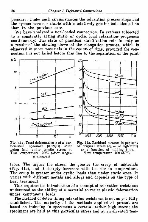
We have analysed a non-loaded connection. I n systems subjected to a constantly acting static or cyclic load relaxation progresses continuously. The state of practical stabilization sets in only as a result of the slowing down of the elongation process, which is observed in most materials in the course of time, provided the con- nection has not failed before this due to the separation of the joint
Fig. I l a . Total deformation e of a car- Fig. I l b . Residual stresses in per cent hon-steel specimen (O . I%C) after of original stress (0, = 25 kgf/mm2) being held under tensile stress a. as a function of holding time. Test temperature 20°C (after Rogan Test temperature 400-450%
Alexander)
faces. The higher the stress, the greater the creep of materials (Fig. I l a ) , and i t sharply increases with the rise in temperature. The creep is greater under cyclic loads than under static ones. I t varies with different metals and alloys and depends on the type of heat treatment.
This requires the introduction of a concept of relaxation resistance understood as the ability of a material to resist plastic deformation wnder continuous loads.
The method of determining relaxation resistance is not as yet fully established. The majority of the methods applied a t present are based on inducing in specimens a certain, rather high stress; the specimens are held a t this particular stress and a t an elevated tem-

1.2. Loaded Connections 27
perature for a long period of time (up to 10 000 hours). Generally, the chosen stress amounts to 0.5-0.6 of the yield limit of the material a t the given temperature.
A split-ring method is the one most often employed. The specimen is a ring with a wedge-shaped cut. The required stress i s produced by forcing a wedge into the cut, which causes bending stresses to develop in the opposite ring section shaped so as to have the same bending resistance throughout its entire length. I n this state the specimen is kept a t the given temperature for the given period of time.
At definite time intervals the load is removed and the residual deformation measured. This is used for calculating the stress remain- ing in the specimen a t the end of each interval.
The diagram shown in Fig. 11 is a result of such tests. The re- maining stresses are shown in Fig. 11b as a function of time and characterize the relaxation resistance of the material. The higher the stress remaining in the specimen (i.e., the lower the residual deformation of the specimen), the greater the relaxation resistance of the material.
The remaining stresses sharply drop during the first 1000 hours of tests and then lower a t a slower pace. This shows that as the holding period grows longer the yielding of the material decreases (seemingly as a result of strain hardening).
The relaxation resistances of various materials are different. Thus, for example, a specimen made from steel grade 40X, after being held a t 400°C for 3000 hours, retains 80% of i t s initial stresses, while one made from steel grade 50X@A retains only 40%. If we convert the results obtained for bending loads to the case of tensile loads, then a bolt made from steel 50XmA will, after 3000 hours' work, extend to a length equal to 60% of i ts initial elastic deforma- tion due to tightening, in which case the tightening force will be reduced by 60%. Naturally, account should also be taken of the above-described effects of the elasticity of the clamped parts and of the working forces which add to the bolt elongation.
Estimating the relaxation resistance by the magnitude of the residual stresses is controversial. To reflect the physical essence of the phenomenon and make calculations more convenient i t is advis- able to characterize the resistance to relaxation by the magnitude of the deformations remaining in the specimen after i ts being held under a load corresponding to the actual loading conditions (for fastening bolts, under a tensile load).
Methods to prevent the weakening of tightened connections as a result of relaxation consist in making bolts from relaxation-re- sistant materials and subjecting them to appropriate heat treatment. Silicon steels possess a high relaxation resistance. Normalizing followed by high tempering is an optimum heat treatment from the standpoint of relaxation resistance. I t seems possible to obtain

28 Chapter I . Tightened Connections
a significant effect by strengthening the bolts through their preli- minazy elongation (ageing) which acceleratively simulates the greatest yield stage of the material.
All measures should be taken to reduce stresses in bolts and the pulsation amplitude of the tension force in cyclically loaded con- nections. I t is also advisable to introduce elastic elements of relaxa- tion-resistant materials so as to compensate for residual deforma- tions as they develop.
(e) Graphical Calculations of Tightened Connections
The totality of the phenomena occurring in tightened connections is easily amenable to graphical interpretation with the help of P-e (force us. relative deformation) diagrams.
Let us take the simplest case, namely, the tightening of a split connection with force P t i g h t (Fig. 12a). I n solving the problem the forces will be plotted on the ordinate axis, and relative deforma- tions - on the abscissa axis, assuming tension to be a positive, and compression, a negative deformation. Line Oa shows the bolt elongation and i ts slope relative to the abscissa axis is
tan a = E ~ F * P
where q = scale of forces y = scale of relative deformations
The compression of the parts being tightened is presented by the straight line Ob whose slope relative to the abscissa axis is
11 tan $ = - E2F2 P
If we draw on the diagram a horizontal line ba a t a distance cor- responding to the tightening force Pt igh t from the abscissa axis, i t will intersect the tension-compression lines a t points a and b, the abscissae of which are equal to the relative deformations el of the bolts and e, of the housing when tightened.
It is more convenient to plot the diagram as shown in Fig. 12b, i.e., by drawing the compression line through point a on the tension line, which corresponds to P = P t i g h t .
Now assume that a force Pwork develops in the joint and that this force imposes an additional load on the bolts while unloading the joint (Fig. 12c).
When determining the bolt tension force, we assume, as previously, that the relative deformations of the bolts and clamped components are the same.
At a distance Pwork (along the vertical) from the bolt tension line Oa draw a straight line (dashed) parallel to it. Through point k,

1.2. Loaded Connections 29
where this line intersects the clamped parts' compression line, draw a vertical line until the latter intersects the tension line (point c). This vertical line will cut off a line-segment of length Ae on the
Fig. 12. Graphical calculations of tightened connections
abscissa axis. Clearly, this scheme reproduces the condition of equal Ae for the bolts and clamped components.
This construction gives all the necessary data. The ordinate of point c shows to scale the bolt tension force Pt,,,; the ordinate of point k, the joint compression force P,,,,; line-segments e; and ei

30 Chapter I . Tightened Connections
relative deformations of the bolts and clamped components after application of working force Pwork.
If the working force pulsates from zero to Pwork , the pulsation amplitude of force Ptens will then equal Ptens - Ptight (the right- hand wavy curve) and that of force PC,,,, Plight - Pcomp (the left-hand wavy curve).
Now let us consider how the system's behaviour is influenced by the variation of the rigidity of bolts and clamped parts (i.e., b y changes in the slope angles a and p of the tension and compression lines, respectively).
Figure 12d illustrates the case of a rigid housing and elastic bolts, while Fig. 12e, that of rigid bolts and an elastic housing. The tighten- ing force Ptight is assumed to be the same in both cases. Figures 12d and 12e clearly illustrate the above-described regularities. The increase of the bolt elasticity with a simultaneous increase in the housing rigidity (reduction of the ratio EIFIIE,F,) lowers the bolt tension force and the pulsation amplitude of this force (see Fig. 12d). At the same time this decreases the joint compression force and in- creases its pulsation amplitude.
Increasing the ratio E,F,/E,F, (elastic housing and rigid bolts) acts in the opposite direction (see Fig. 12e): force Ptens and the amplitude of i ts pulsation increase, PC,,, rises too, but the ampi- tude of its pulsation decreases.
As stated earlier, when determining connection parameters i t is more proper to proceed from the condition of proportionality between the compression force and working pressure (PC,,,= = 0Pwork).
In this case the graph is plotted in the following order (Fig. 12f). First, draw horizontals a t distances PC,, = 8PWork and PtenS = = ( I + 8) PWork from the abscissa axis (n Fig. 12f i t is assumed that 0 = 0.6). Then from any arbitrary point draw a t an angle p an inclined line representing the housing compression. From point d a t which this line intersects the horizontal line P,,,, draw a ver- tical until i t meets the horizontal line Ptens and through point e of their intersection draw at an angle a an inclined linerepresenting the bolt tension. The ordinate of point f , where the two inclined lines intersect, gives the value of the tightening force Ptight.
The difference Ptens - Ptight shows, as before, pulsation ampli- tude of force PtenS, and the difference Plight - Pcompr the pulsation amplitude of force PC,,,.
Figures 12g and 12h show how the rigidity of the housing and bolts influences the operation of the joint (with Pwork and 0 values being the same as above). I n the case of elastic bolts and a rigid housing (Fig. 12g) force Ptight increases, the pulsationamplitude of force Ptens decreases and the pulsation amplitude of force PC,,, increases.

1.2. Loaded Connections 32
In the case of rigid bolts and an elastic housing (Fig. 12h) the force Ptight decreases, the pulsation amplitude of force Pten, increas- es and the pulsation amplitude of force PC,,,, decreases.
For an unloaded connection (Pwork = 0) subjected to heating, which causes a thermal stress Pt to develop in the joint (Fig. I Z i ) , one should draw a line parallel to and spaced from the compression line a t a distance of a , t , - altl (along the horizontal), equal t o the relative deformation due to the heating. The ordinate of point a', a t which this line intersects the tension line, is equal to PtenS (iden- tical to force PC,,, compressing the housing) after the heating; the difference between the ordinates of points a and a' represents the thermal stress P t .
For connections which are simultaneously subjected to heating and to the action of force Pwork the plotting differs in that the inclin- ed tension and compression lines are set apart (horizontally) a t a distance of a , t , - altl (Fig. 12j). The rest of the construction i s as before.
The elasticity characteristic of the clamped parts does not always follow the linear relation P = eE,F,. Such is, for instance, the case with thin-walled intricately shaped components whose walls in certain areas are either inclined or perpendicular to the direction of the compressive force. Here the compressive deformations of the walls are complemented with the elastic bending deformations of their inclined and horizontal portions. Furthermore, the walls may be subject to buckling. If so, the rigidity of the clamped parts sharply drops and the characteristic curve assumes a gently sloping shape.
Occasionally the elasticity characteristic becomes curvilinear because the individual elements of a construction come into opera- tion not a t the same time, but one after another as the load increases. The elasticity characteristic of such complex constructions can only be determined experimentally. To this end a fully finished construction is subjected to compression on a test rig and i ts elasti- city characteristic is plotted point by point on the basis of the test data.
I n this instance the graphical method of calculation is the only way possible. The curve obtained from the test is plotted on the graph in place of the inclined line P = eE,F, (Fig. 12k, I ) . Further construction is as described above.
When calculating for a known force P,,,, = 8PWork, the curvi- linear nature of the characteristic has an effect on the magnitude of the tightening force and of the pulsation amplitude of forces Pt,,, and PC,,,. With aconvex characteristic (Fig. 12 k) the required force Ptight diminishes, the pulsation amplitude of force Pten, increases and that of force P,,,, decreases. If the characteristic i s concave (Fig. 121) the picture is reversed.

3 2 Chapter I . Tightened Connections
Cf) Methods of Controlling the Tightening Force (Preload) Because the preload has a great effect on the bolt tension and joint
compression forces, it is very important during assembly to strictly keep to the calculated magnitude of the tightening force. This is achieved by tightening nuts with torque wrenches, by turning them through calculated angles or by measuring the elongation of bolts.
The application of torque measuring wrenches does not provide for adequate accuracy, since the force needed to tighten nuts depends t o a large extent on the thread condition, coefficient of friction in the threads and on the bearing surfaces, etc. For this reason, bolts tightened with the same torque may, in fact, be loaded differently.
To lessen the friction effect critical connections are sometimes tightened on a vibration table. The rather sharp decrease in the friction forces because of vibration must be considered when choosing the design tightening torque.
When tightening nuts by rotating them through a calculated angle they are first brought into close contact with the bearing sur- faces, i.e., up to the point when bolts begin to extend. After this the nuts are turned with a wrench through the required angle v.
This angle is determined from the given tightening force Pt ight , proceeding from the following considerations.
When tightening a nut, it is necessary to choose the bolt elonga- tion h -- 'ti"t ' and clamped parts contraction 1, = '*'.
- E*F{ The axial displacement of the nut relative to the bolt is
The tangent of the thread helix angle S tan cp = -
ndo where s = thread pitch
do = thread pitch diameter The displacement of the nut by value h corresponds to its rotation
over arc C of the circumference of radius do/2
h c=- tan cp
On the other hand, the value of C is
where v is the nut rotation angle in radians, and vO, the same in degrees.

1.2. Loaded Connections 33
Equating Eqs. (1.36) and (1.37), we have o 360" y =-.-
tan cp ndo
Substituting into this equation h and tan cp from Eqs. (1.34) and (1.35), we have
1 1 1 v0 = 360" Pt ight 7 + -) (1.38)
Clearly, the tightening angle is independent of the bolt diameter. Nuts are practically tightened by the following method. First
all the clearances in the system are taken up (by tightening all the nuts home in a certain succession). This done, the nuts are slackened off and again tight- ened by hand or by means of a light torque-control wrench un- til the nuts are in close contact with the bearing surfaces. The- reafter all the nuts are tightened in a definite sequence (staggered, cross-like, serpentine-like) de- pending on the configuration of the joint faces and assuring apn i - form tightening of the connec- tion by turning them first through an angle of v/2 and then, in the same succession, through the full angle v.
To measure the nut rotation angle the wrench is provid- ed with pointer and the tight- ened a graduated Fig. 13. Wrench design enabling ac- disk. curate measurement of nut turning
This method is more accurate angle relative to bolt than the first one, although it also contains sources of errors due to the difficulty of determining the right moment to start the tightening. I t is only by fitting experience that this error can be reduced to minimum.
I n respect to slender bolts and studs the accuracy of measurement is influenced by their twisting during tightening, which is due to friction in the threads. To eliminate the twisting, the bolt end is held with a spanner when tightening (see Fig. 3a). However, this method is not convenient in actual fitting. Figure 13 depicts a wrench design which excludes any effect of the bolt twisting upon the accu- racy of the tightening angle measurement.
Inserted into the wrench stem is a spring-loaded locking device 1 having a tapered end with a tapered shank of cross-like section, 3-01418

34 Chapter I . Tightened Connections
which fits into a corresponding socket in the bolt end. The locking device is spline-connected with rod 2 whose projecting end holds a friction-mounted pointer 3 positioned over graduated dial 4 attach- ed to the wrench end face.
As the wrench is applied to the nut, the locking device enters the bolt socket, thus providing a direct connection between the bolt and pointer. Prior to tightening, the pointer is set to the dial zero position. During the tightening the pointer indicates the rotation
angle of the nut relative to the bolt, i.e., the nut tightening angle.
The most accurate method is that whereby the bolt elongation, i.e., A=- I is measured directly.
EiFi ' The elongation of short bolts i s measured by means of a micrometer cal- liper gauge. The technique is appli-
Fig. 14. Control of tightening cable whenever the calliper jaws can
force by means of deformable be directly applied to the bolt ends. ring I n this was, for example, is measured -
the elongation of connecting rod bolts, pinch bolts in clamp connections, fastening bolts of hydraulic cylin- ders, etc. For greater measuring convenience the bolt head and stem end are made spherical.
The elongation of studs can be measured with the aid of an indica- tor, if its foot is set up on an independent support. When installed on the component being tightened the indicator will read the total of the elongation of the stud and the contraction of the tightened parts.
Sometimes the tightening force is controlled by means of a system of deformable washers (Fig. 14). Rigid washers 1 and 2 and measuring ring 3 of a plastic metal (e.g., annealled copper) are placed under the nut. Reference washer 4 is placed concentrically around the measuring ring. The thickness of ring 3 is selected so that after the preliminary, light tightening of the nut a design clearance e (equal to the sum of elastic deformations in the tightened system) remains between the ring and reference washer. As the nut is finally tightened the measuring ring is flattened out. The tightening is stopped when the clearance e is taken up completely (this being indicated by the reference washer losing i ts mobility).
The measuring ring must be changed whenever the nut has to be retightened.
( g ) Calculation Example An engine cylinder block having a cross-section as shown in Fig. 15 is fasten-
ed to the crankcase by means of studs 400 mm long; the stud stem diameter is 18 m, thread M24 (pitch s = 1.5 mm).

1.2. Loaded Connec t ions 35
As~ume that the ignition force Pu,ork = 10 000 kgf is taken up by the four studs nearest to the cylinder and that the studs' tightening force spreads over
0 0
0 0 Fig. 15. Cross-sectional view of cylinder block
the block portion adjacent to the cylinder (delimited by lines 0-0 in the Figureg with a cross-sectional area of 7000 mm2.
The block is made from aluminium alloy grade AJI5 (E, = 7500 kgflmm2, a, = 22 . l o - 6 ) ; the studs are of steel grade 3UXrC (E l = 21 000 kgf/mm2; a, = 11 -10-6). The temperature of the block and studs in the running engine is 80°C.
Find the maximum stresses in the studs and crankcase in both the cold (dead) and hot (running) engine.
Assume that 0 = 0.5. Joint compression force
PC,,, = 0.5PWork = 5000 kgf Total stud tension force [Eq. (1.22))
Ptens (1 $0.5) Pwork ' 1 5 000 kgf Tension force per stud
l 5 OoO - 3750 kgf Ptens. i = 7- Tensile stress in studs
3750 = 15 kgf/mm2 = 0.785.182
Compressive stress in cylinder block Pcomp
ocomp = - = - 5000 - - 0.7 kgf/mmz F2 7000
Total tightening force PtiRht [Eq. (1.24)] required 1
Ptighl=puoii 0+ E~~~ ) 1 I-
Factor E,F, E2F,
EiFi-21 000 4.0.785.182=2.1.107 kgf Factor E2F,
E2F,=7500.7000=5.3.10' kgf Hence.

36 Chapter I . Tightened Connections
Angle through which nuts must be turned when tightening [Eq. (1.38)]
Thermal stress in the joint when heated [Eq. (1.25)]
By hypothesis, t , = tl = 806C. Substituting numerical values, we have
Pt=80(22-11)-10-& 2'1.107 =I3000 kgf 2 .1
After heating: 1+5.3
stud tension force
P;,=Pt,n,-!-Pt= 15 000$13000= 28 000 kgf
joint compression force
P&,, = + Pt = 5000 + 13 000 = 18 000 kgf
tensile stress in studs
( ~ { e n a = *;em - 28 OoO = 28 kgf /mm2 4.0.785d2 - 4.0.785.182
compressive stress in cylinder block
tension force pulsation amplitude
Atens=P;ens-(Ptfght$.Pt)=28 m 0 - ( 1 2 000+ 13 000) = 3000 kgf
coefficient of cycle skewness
compression force pulsation amplitude
Acomp=Ptight+Pt-P~omp= 12 000f 13 000- 18 000 = 7000 kgf
coefficient of cycle skewness
' b e fatigue limit of steel grade 30XI"C under a .pulsating cycle with a coef- ficient of skewness of 0.9 equals 75 kgf/mma. The fatigue limit of aluminium alloy grade AJI5 under a pulsating cycle with a coefficient of skewness of 0.7 equals
7 5 8 kgflmma. Consequently, the safety factor for the studs is- = 2.7 and that 28
for the cylinder blocks, - = 3. 2.6

Chapter 2
Press-Fitted Connections
Press (drive) fits are extensively applied in general engineering to make permanent joints or those seldom dismantled. The relative displacement of press-fitted parts is prevented by the forces due to elastic compressive deformation (in the male part) and tensile deformation (in the female part), which are proportional to the amount of interference in the joint.
2.1. Press (drive) Fits
The USSR State Standard I'OCT 7713-62 stipulates the following press fits for the basic hole system.
1st grade o f accuracy 2nd grade of aceuraey
1st heavy drive fit (Dhli) . . . Light drive fit (Dl) . . . . . Iln 2nd heavy drive fit ( D h 2 4 . . . 1 7 ~ 2 ~ Heavy drive fit (Dh) . . . . I7p
Shrink fit (Sh) . . . . . . . I'p
2a grade of accuracy 8rd grade o f accuraw
1st heavy drive fit (Dhlza) . . . 17p12, 1st heavy drive fit (Dh13) . . . n p l ) 2nd heavy drive fit (DhZ*,) . . . IlpZ2, 2nd heavy drive fit (DhZ3) . . . Llpas
3rd heavy drive fit (DM3) . . . 1 7 ~ 3 ~
Figure 16a gives mean interferences A,,,, ym as a function of the shaft diameter d mm for different press fits; Fig. 16b-mean
Arnean relative interferences pm/mm and 7 . d
From Fig. 16b i t is seen that the relative interferences sharply increase in the small diameter range. For this reason one must be especially careful when designing small diameter joints since the strength of press-fitted parts depends first of all on the amount of their relative interference.
Light drive fits (Dl) are obtained with the least interferences, Fits Dhl l are close to the latter in terms of the mean interferences. Fits DhZ,, Dh, Dhl,, and Dhl, are practically the same as far as

38 Ch,apter 2. Press-Fitted Connections
the mean interferences are concerned, the only difference being that the fits to lower grades of accuracy have wider tolerances. Mean interferences are practically the same in the case of fits Sh and
Fig. 16. Mean interference A,,,, and relative interference Am,,,/d as a func- tion of connection diameter d for different fits
Dh2,. The greatest (and almost identical) mean interferences are in the case of fits Dh2,, and Dh3,.
The relationship between the mean interference and diameter is approxi- mately expressed by the formula
Amean ~m ( D m m S 60) (2.1) The proportionality factor 9 for various fits is as follows
Fits . . . . . Dl Dhli Dh DhZ1 Dh13 Dh12, Sh DhZ3 DhZ2, Dh3,
9 . . . . . . . 0.23 0.28 0.46 0.44 0.5 0.54 0.95 0.98 1.13 1.16
2.2. Strength of Press-Fitted Connections
The axial holding power of a press-fitted connection is
Pa, = kFf kgf (2.2) The torsional holding power
d .Wio,,= 0.001kFf kgf.m (2.3)
where k = unit pressure on the surface of joint, kgf/mm2 F = ndl = joint surface area, mm2

2.2. Strength o f Press-Fitted Connections 39
f = coefficient of friction between mating surfaces (for steel and cast iron, on the average, f = 0.1-0.15)
d, I = d.iameter and length of the surface of joint, mm The unit pressure on the surface of joint is found from Lame's
equation
where A - = relative diametral interference d
E l , E , and p,, p2= elastic moduli (in kgf/mm2) and Poisson's ratios of the materials of the male and female parts, respectively
c, and c, = coefficients expressed as
where dl and d, are the inner diameter of the male part and the outer diameter of the female part, respec- tively.
d a,. The quantities a, and a, Let us designate $ = a, and - =
may be called the relative wall Zickness of the male and female parts, respectively. When a, = a, = 1 the thicknesses of the male and female parts equal zero. Values a, = a, = 0 correspond to the case of massive male and female parts.
Coefficients c, and c, may be expressed in a general form as follows (Fig. 17):
Equation (2.4) shows that unit pressure ,k and, consequently, the joint strength are proportional to the relative diametral inter- ference Ald, increasing with the increase of Young's moduli of the materials and decreasing with the increase of c, and c,, i.e., with the enhancement of the wall thickness factor a.

40 Chapter 2. Press-Fitted Connections
The compressive stress in the male part is maximum on its internal surface and is expressed as
The maximum permissible unit pressure determined by the bearing strength of the material is
k = %ear (2.8) where crbear is the ultimate bearing strength of the material.
The reduction in the internal diameter of the male part
c Ai w -dl (Ji E l (2.9)
10 The tensile stress in the female
part is maximum on i ts inter- nal surface and is expressed as
8 2k A 2 (Tz=-- -.- 2 x I-a:- d I-a,
6 X 1
C % - - W l cz+p2 (2.10)
Ei +-
E2 4
The increase in the external diameter of the female part
2 A, (2.11j
Ez
o a2 ne 0.6 0.8 Q=g Equations (2.4), (2.7) and (2.10) enable some general con-
Fig. 17. Coefficient c as a function clusions to be drawn. , of wall thickness factor a To simplify the problem as-
sume that both the [female and male parts are made of the same material (El = E, = E; p1 = = p, = p). Then Eqs. (2.4), (2.7) and (2.10) become
A k=-.- kgf/mm2 d ci-tc,
(2.12)
A 2 oi=-.-. - kgf/mm2 d 1-a: ci+c2
(2.13)
A 2 ( J ~ = - . ~ .- kgf/mm2
d l -a , cl+c2 (2.14)
Figure 18a shows as a function of a, and a, the relative pressure k, = - ' which is the value of pressure k when AEld = 1.
ci + cz

2.2. Strength o f Press-Fitted Connections 49
The pressure (and consequently the strength of the joint) is maximum when a, = a, 2 0 (both the male and female parts are massive) and decreases with the increase of a, and a, (i.e., with the decrease of the wall thickness of both the male and female parts), tending to zero when a, = a, = 1.
The reduction of the pressure with the decrease of the wall thick- ness of the male and female parts can be compensated for by increas- ing the diameter and length of the surface of joint. If, as is usual.
Fig. 18. Effect of wall thickness factors a, and a, on values of k,, ao, and ao,
the length of connection is proportional to its diameter, i.e., 1 = = nd (n = coefficient of proportionality), then, according to
d3 Eqs. (2.2) and (2.3), Pa, = kf n# and Mtoj-s = kfn T . Hence, the resistance of a joint to an axial shift is proportionaP
to the square of its diameter, and i ts resistance to torsion, to the cube of the diameter.
From Eqs. (2.13) and (2.14) the relative stresses o,, and o,, ( the stresses with AEId = 1) are
These relationships are diagrammed in Fig. 18b. From the graph the following conclusions can be drawn:
stresses o,, in the male part (heavy lines) are maximum (ool = 1) with a massive female part (a, = 0); they decrease as the wall thick- ness of the female part is reduced (a, + 1) and increase as the wall thickness of the male part is reduced (al + 1);

-42 Chapter 2. Press-Fitted Connections
stresses go, in the female part (light lines) are maximum (o,, = 1) with a massive male part (a, = 0); they decrease as the wall thick- ness of the male part is reduced (al + 1) and increase as the wall -thickness of the female part is reduced (a, + 1).
Assuming that the male part is a shaft, and the female part, a hub, the following rules can be formulated:
to increase the strength of the shaft i t is necessary to increase the thickness of i ts walls and decrease the wall thickness of the hub (massive shaft and thin-walled hub). This rule is applied when the hub strength is of no concern;
to increase the hub strength i t is necessary to increase the thick- ness of i ts walls and to decrease the wall thickness of the shaft (mas- sive hub and thin-walled shaft). The rule is applied when the shaft is of sufficient strength.
When the male and female components of a joint are made from dissimilar materials, the above relationships are affected by the rigidity of the materials. If one of the parts (female or male) is made from a material having a smaller elastic modulus (E') than the other 'one (Eft), then the unit pressure and the stresses in the parts fall approximately in proportion to the ratio E'IE" (to a greater degree in the part made from the material of the greater elastic modulus).
The best relationship between the wall thicknesses of the hub and shaft should be established in each particular case by individual .calculations.
(a) Coefficient of Friction
The strength of press-fitted connections is directly proportional to the coefficient of friction between the mating surfaces [see Eqs. ,(2.2) and (2.3)l.
The coefficient of friction depends on the pressure on the contacting :surfaces, the magnitude and profile of surface microirregularities, the material and state of the mating surfaces (presence of oil) and .also on the assembly technique (connection with the aid of a press, with heating or cooling the parts).
The coefficient of friction rises with an increase in the surface roughness and lowers with a rise ~ I I the unit pressure. I t is higher when the assembly is done with heating or cooling as compared with -a press-fitting. The coefficient can substantially be enhanced by .electroplating.
Depending on the above factors the coefficient of friction ranges from 0.08 to 0.3, and sometimes may be even higher. Obviously no accuracy in calclilations can be expected with such an extensive f value scatter. The primary value of the calculation is that i t enables .one to determine the influence of the geometry and rigidity of the connection elements on the joint strength and outline rational ways to improve it.

2.2. S trength o f Press-Fitted Connections 43
In practice lower coefficients of friction ( f = 0.1-0.15) are gene- rally adopted, including possible increase in the coefficient above these values. in the safety factor.
(b) Effect of Su1.face Finish
An adequate surface finish of the mating components is an essential condition for the strength of pressed connections. ,
The measured hole and shaft diameters include the height of microirregularities which are flattened in the course of press-fitting.
Fig. 19. Mean interferences with Dh grade fit (heavy line) and roughness heights for various classes of surface finish as a function of connection diameter d
If the height of surface microirregularities is commensurate with the interference of mating parts, the actual interference in the pressed connection will then be appreciably smaller.
Shown in Fig. 19 are the mean values of interferences in the case of a heavy drive fit (Dh) for different shaft diameters, and the total roughness height R, of the shaft and the hole when machined to the 4th-8th class of surface finish. From the graph i t is clear that small-diameter connections (less than 30-40 mm) must not be machined worse than to the 6th class because the total roughness height in this case becomes close to the interference value. Hence, in such connections the interference will either be substantially reduced or disappear altogether after the microirregularities are flattened.

44 Chaoter 2. Press-Fitted Connections
Connections with diameters of the order of 50 mm and more, a s well as connections with greater interferences, may be machined somewhat rougher. I n practice the surfaces of the mating parts in medium-size press-fitted connections are machined to the 8th-10th and 7th-9th classes of surface finish (for shafts and holes, respec- tively).
Microirregularities have a certain positive effect on the strength of the connection as they act like spurs enhancing the bond between the contacting surfaces. Experiments show that machining better than to the 11th class of surface finish impairs the joint strength because of the reduced coefficient of friction between the contacting surfaces.
Design Eqs. (2.4), (2.7) and (2.10) include the actual interference value. Therefore, when designing pressed connections the assigned nominal interference A,,, should be reduced by the amount of the expected flattening of microirregularities
where RZ1 and R,,= roughness height of the shaft and hole, respectively, ym
q = flattening coefficient The amount of the flattening of the microirregularities depends
on the interference in the joint, the height of the irregularities, their shape and profile, the density of distribution of the irregularities, the hardness and strength of the material of the mating parts, and the hardness relationship between the surfaces of the female and male parts.
The amount of flattening is largely dependent on assembly con- ditions. When assembling in a press, the surface irregularities are successively sheared off in the course of longitudinal movement and are flattened much more than in the case of assembly procedures whereby the parts are heated or cooled (i.e., when the surface irre- gularities are reduced radially).
The actual amount of flattening, determining the operational strength of the connection, depends on the magnitude and type of the load acting upon the connection and also on the number of assembly-dismantling procedures. I t is established only after a certain period of operation.
The height of the surface microirregularities decreases with each assembly-dismantling procedure and settles a t a definite level after three or four such procedures.
Naturally, i t is impossible to duly account for all these faetors. Therefore, as a first approximation in calculations i t is assumed that the flattening of surface microirregularities averages 0.5-0.6 of the original mean roughness height. The effect of the subsequent

2.2. Strength of Press-Fitted Connections 45
operation of the joint is accounted for by a safety factor which for pressed connections is taken a t 2-4.
Assuming cp = 0.5, we find A' = RZ1 + R,, and introducing the value An,, - A' into Eq. (2.3), obtain
When the required nominal interference is to be found, the amount of the microirregularity flattening should be added to the calculated interference magnitude
Anom = Aealc + Rzi + Rzz (2.17)
Then this nominal interference value is used as a reference for selecting the corresponding fit from the standard.
For the 6th-11th classes of surface finish R, has the following values:
Class of surface finish . . . 6 7 8 9 10 I 1 R,, pm . . . . . . . . . . I0 6.5 3.2 1.6 0.8 0.4
Corrections for the flattening of microirregularities are substantial when dealing with small-diameter connections. For instance, when d = 30 mm the average interference for a heavy drive fit (Dh) is 33 pm. If the mating surfaces are machined to the 8th class of surface finish the correction Rzl + RZ, = 6.4 p a amounts to approximate- l y 20% of the nominal interference. For a joint with d = 150 mm (interference 110 pm) the correction will amount to approximately 6%.
( c ) Effect of Thermal Deformations
For connections undergoing heating during operation, the influence of temperature upon the fit must be considered. If the female part i s made from a material having a higher coefficient of linear expan- sion, or is heated in operation more intensively than the male part, the original (cold) interference in the joint will then be reduced during heating.
Conversely, if the male part is made from a material having a higher coefficient of linear expansion, or is heated in operation more intensively than the female part, the original interference will be enhanced during heating.
Whenever heating is involved, Eqs. (2.4), (2.7) and (2.10) must include the temperature interference (with i t s sign)
where al and az = linear expansion coefficients of the male and female parts, respectively
46 Chaoter 2. Press-Fitted Connections
At, and At, = temperature increments in the heating of the male and female parts, respectively
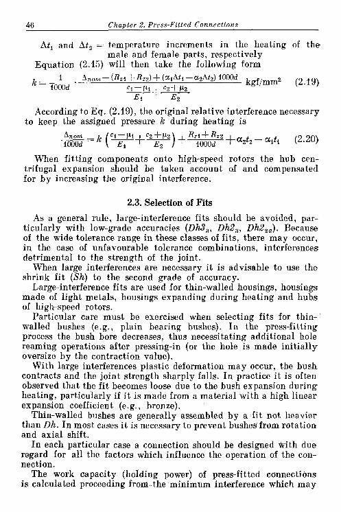
Equat,ion (2.15) will then take the following form
According to Eq. (2.19), the original relative interference necessary to keep the assigned pressure k during heating is
When fitting components onto high-speed rotors the hub cen- trifugal expansion should be taken account of and compensated for by increasing the original interference.
2.3. Selection of Fits
As a general rule, large-interference fits should be avoided, par- ticularly with low-grade accuracies (Dh3,, DhZ,, DhZ,,). Because of the wide tolerance range in these classes of fits, there may occur, in the case of unfavourable tolerance combinations, interferences detrimental to the strength of the joint.
When large interferences are necessary i t is advisable to use the shrink fit (Sh) to the second grade of accuracy.
Large-interference fits are used for thin-walled housings, housings made of light metals, housings expanding during heating and hubs of high-speed rotors.
Particular care must be exercised when selecting fits for thin- walled bushes (e.g., plain bearing bushes). In the press-fitting process the bush bore decreases, thus necessitating additional hole reaming operations after pressing-in (or the hole is made initially oversize by the contraction value).
With large interferences plastic deformation may occur, the bush contracts and the joint strength sharply falls. In practice i t is often observed that the fit becomes loose due to the bush expansion during heating, particularly if it is made from a material with a high linear expansion coefficient (e. g., bronze).
Thin-walled bushes are generally assembled by a fit not heavier than Dh. In most cases i t is necessary to prevent bushes from rotation and axial shift.
In each particular case a connection should be designed with due regard for all the factors which influence the operation of the con- nection.
The work capacity (holding power) of press-fitted connections is calculated proceeding f r o a the minimum interference which may

2.4. Calculation Diagrams 47
arise with an unfavourable combination of the hole and shaft sizes (hole made to the upper tolerance limit and shaft, to the-lower tole- rance limit)'.
Stresses arising in female and male parts, as well as the force needed to assemble and dismantle press-fitted connections, are calculated on the basis of the maximum interference (hole made t@ the nominal size, and shaft, to the upper tolerance limit).
2.4. Calculation Diagrams
On the basis of Eqs. (2.4), (2.7) and (2.10) diagrams are drawn which ease time consuming pressed-connection calculations, allow- the influence of pressed-connection parameters on the joint strength to be traced and indicate rational ways of strengthening.
Shown in Fig. 20 is a calculation diagram for male and female parts made from the same material [Eqs. (2.12)-(2.14)l.
The lower portion of the diagram presents the values of relative
pressure k - - as a function of a, for different magnitudes O - ci+cz
of a,. The top part of the diagram gives relative stresses oo, equal for the male and female parts
Absolute values of k, o, and o, are obtained by multiplying the values of ko, ool and oo, by the factor AEld.
Let us now consider the use of the diagram by an example.
Given: a hollow steel shaft with external diameter d = 100 mm and internal diameter dl = 70 mm (a, = 0.7) is pressed into a steel hub with external dia- meter d, = 125 mm (a, = 0.8) by asshrink fit (Sh). The connection length is 100 mm. Both the shaft and hole are machined to the 8th class of surface finish (RZl + R,, = 6.4 ym). The coefficient of friction f = 0.1.
Find: pressure k on the surface of joint, torsional holding power Mt,,, and maximum stresses o in the shaft and o, in the hub.
First determine the AEld value. For the Sh fit the mean diametral interfe- rence when d = 100 mm is 120 pm. Hence, the actual interference is 120-6.4 = = 113.6 ym. Young's Modulus E = 21 000 kgf/mm2. Then
From the point a, = 0.7 (lower portion of the diagram) draw a horisontat line to intersect curve a, 0.8 (point a) and read on the abscissa the value k, = 0.135. The pressure is
The tprsional holding power [see Eq. (2.3)] is , 1 1 1 . .
Mt,,, = 0.001~3.24~0.1rn~100:100~50=500 kgfem

Fig. 20. Diagram for computing press-fitted joints (parts made of the material)
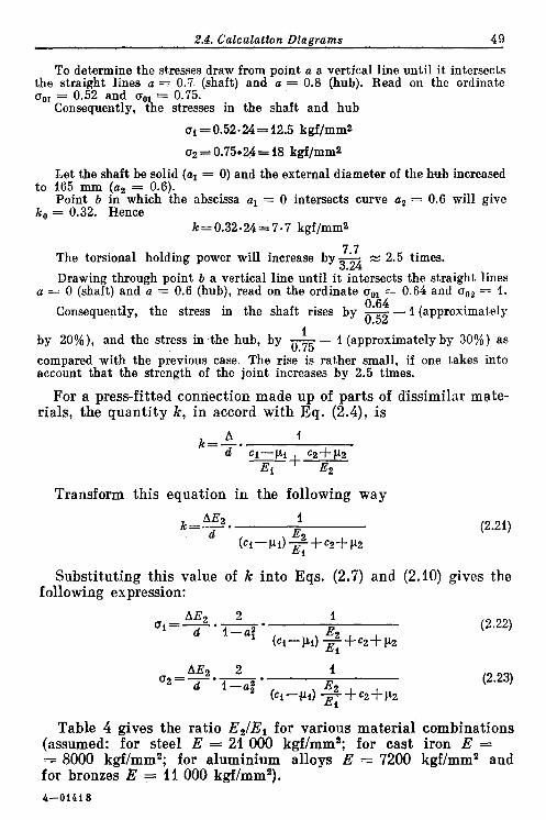
2.4. Calculatton Diagrams 4 9
To determine the stresses draw from point a a vertical line until it intersects the straight lines a = 0.7 (shaft) and a = 0.8 (hub). Read on the ordinate o,, = 0.52 and a, = 0.75.
Consequently, b e stresses in the shaft and hub
ai = 0.52-24 = 12.5 kgf/mm2
bet the shaft be solid (al = 0) and the external diameter of the hub increased to 165 mm ( a , = 0.6).
Point b in which the abscissa al = 0 intersects curve a, = 0.6 will give k, = 0.32. Hence
k=0.32.24=7-7 kgf/mm2
The torsional holding power will increase by g4 z 2.5 times.
Drawing through point b a vertical line until i ; ~ ~ e r s e c t s the straight lines a = 0 (shaft) and a = 0.6 (hub), read on the ordinate o,, = 0.64 and a,, = 1.
0.64 I (approximately Consequently, the stress in the shaft rises by - - 0.52
1 (approximately by 30%) as by 20%), and the stress in the hub, by - -..- compared with the previous case. The rise is rather small, if one takes into account that the strength of the joint increases by 2.5 times.
For a press-fitted connection made up of parts of dissimilar mate- rials, the quantity k, in accord with Eq. (2.4), is
Transform this equation in the following way
Substituting this value of k into Eqs. (2.7) and (2.10) gives the following expression:
Table 4 gives the ratio E2/El for various material combinations (assumed: for steel E = 21 000 kgf/mm2; for cast iron E = = 8000 kgf/mm2; for aluminium alloys E = 7200 kgf/mm2 and for bronzes E = 11 000 hgf/mma). 4-01418
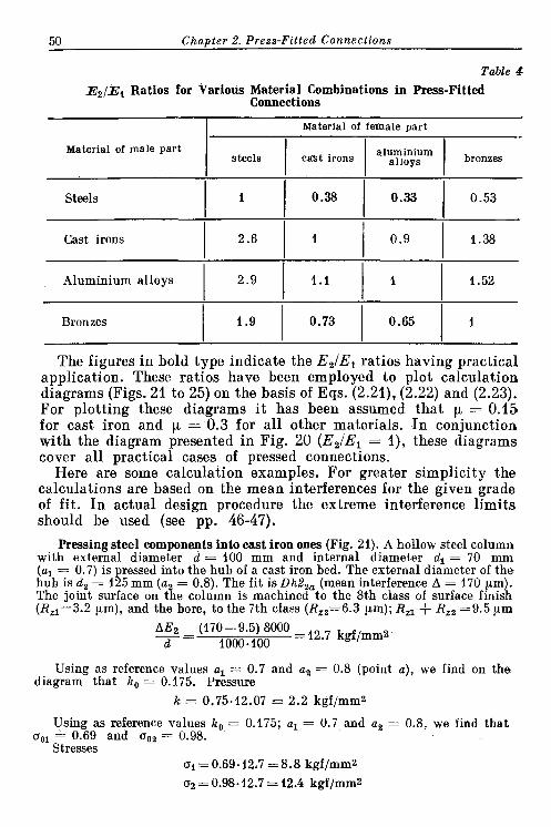
50 C h a ~ t e r 2. Press-Fitted Connections
Table 4 E ~ / E ~ Ratios for Various Material Combinations in Press-Fitted
Connections
I Material of female part
Material of male part
Steels I I 1 0.38 1 0.33 1 0.53
Cast irons 1 2.6 1 1 / 0.9 1 1.38
Aluminium alloys I 2.9 I 1.1 I I 1 1.52
Bronzes 1 1.9 1 0.73 1 0.65 1 1
The figures in bold type indicate the E,IEl ratios having practical application. These ratios have been employed to plot calculation diagrams (Figs. 21 to 25) on the basis of Eqs. (2.21), (2.22) and (2.23). For plotting these diagrams it has been assumed that p = 0.15 for cast iron and p. = 0.3 for all other materials. In conjunction with the diagram presented in Fig. 20 (E21El = I ) , these diagrams cover all practical cases of pressed connections.
Here are some calculation examples. For greater simplicity the calculations are based on the mean interferences for the given grade of fit. In actual design procedure the extreme interference limits should be used (see pp. 46-47).
Pressing steel components into east iron ones (Fig. 21). A hollow steel column with external diameter d = 100 mm and internal diameter dl = 70 mm (a, = 0.7) is pressed into the hub of a cast iron bed. The external diameter of the hub is d, = 125 mm (a, = 0.8). The fit is Dh2,, (mean interference A = 170 pm). The joint surface on the column is machined to the 8th class of surface finish (R,,=3.2 pm), and the bore, to the 7th class (R,,=6.3 pa); R,, $- R,, =9.5 pm
Using as reference values a, = 0.7 and a, = 0.8 (point a), we find on the diagram that k, = 0.175. Pressure
k = 0.75-12.07 = 2.2 kgf/mmz
Using as reference values k, = 0.175; a, = 0.7 and a, = 0.8, we find that o,, = 0.69 and a,, = 0.98.
Stresses ai = 0.69.12.7 = 8.8 kgf/mmZ 02 = 0.98.12.7 = 12.4 kgf/mmZ

Fig. 21. Diagram for computing press-fitted joints (steel parts pressed in cast-iron parts)

52 Chapter 2. Press-Fitted Connections
Reduce the internal diameter of the column to 60 mm (a, = 0.6) and increase the external diameter of the hub to 165 mm (a, = 0.6). In this case (point b) k, = 0.34 and 00, = oo, = 1.06. Hence,
k=0.34.12.7=4.3 kgf/mm2
ai = = 1.06.12.7 = 13.5 kgf/mmZ
4 3 The strength of connection is increased by -L z 2 times, the stresses in the 2.2
13 5 column and hub rise approximately by - - 1 (approximately by 50%) and
8.8 13.5 - - 1 (approximately by lo%), respectively. 12.4
Pressing steel components into those of aluminium alloys (Fig. 22). A hollow steel shaft with d = 100 mm and dl = 70 mm (a, = 0.7) is press-fitted into the hub of a housing cast in an aluminium alloy. The external hub diameter d, = 150 mm (a, = 0.65). The grade of fit is Dh2,, ( A = 170 pm). The class of surface finish of the shaft is the 8th (R,, = 3.2 pm) and that of the hole, 7th (RZz = 6.3 pm); RZ1 + R,, = 9.5 pm.
On the diagram, for a, = 0.7 and a, = 0.65 (point a) we find that k = 0.275; a,, = 1.09; o,, = 0.92.
Hence k =0.275.11.5 = 3.15 kgf/mmz
a i = 1.09.11.5 = 12.5 kgf/mm2 a2= 0.92.11.5 = 10.6 kgf/mm2
Stresses a, in the hub exceed the yield limit for cast aluminium alloys in tension (o,, = 10 kgf/mm2). To reduce the stresses we use the fit grade Dhl,, abtained with a smaller interference (A = 90 pm).
Then
5 8 The values of k, a, and a, decrease by a factor of - z 0.5. The stress a,
11.5 -- - Becomes acceptable: 0.5 -10.6 = 5.3 kgf/mm2.
Let us now considerTte=case of pressing a disk of a wrought aluminium alloy a n t o a hollow steel shaft with external diameter d = 100 mm and internal diameter dl = 70 mm (a, = 0.7). The disk can be regarded as a solid part (a, = 0). The grade of fit is Dh (A = 65 m). The class of surface finish of the shaf t is the 9th (R,, = 1.6 pm), and t i a t of the disk bore, 8th (R,, = - 3.2 pm); R,, + R,, = 4.8 pm
From the diagram we find (point b ) that ko = 0.465; ool = 1.82; a,, = 0.92. Hence
k = 0.465 4 . 3 = 2 kgflmmz
01 = 1.$2:4.3= 8 kgf/mmz a2=0.92.4.3=4 kgf/mmz

Fig. 22. Diagram for computing press-fitted joints (steel parts pressed in parts of aluminium alloys)

54 Chapter 2. Press-Fitted Connecttons
Assume that during operation the disk temperature rises by 100°C (in compari- son to the assembly temperature) and the shaft remains cold. As the linear expansion coefficient of an aluminium alloy a, = 22 -10-6, the disk bore dia- meter will increase in heating by the value
Thus, the original press-fit interference vanishes and instead a clearance amounting to 220-(65-4.8) = 160 pm develops in the joint.
To keep the alignment of the parts a fit of greater interference should be employed, for example, that of the grade DhZ,, (A = 180 ym). In this case during heating of the joint there develops a clearance amounting to 220-(180-4.8) = = 45 pm which does not disturb the alignment.
With an interference of 180 pm
12 6 The values of k, 0, and a, increase by a factor of z 3. Stress a, in the
disk hub (in cold state) becomes a, = 3 -4 = 12 kgf/mm2; which is acceptable for wrought aluminium alloys.
Pressing bronze components into steel ones (Fig. 23). A tin-bronze bush with external diameter d = 40 mm and internal diameter dl = 35 mm (a, = 0.87), is press-fitted into a steel hub with external diameter d, = 53 mm (a, = 0.75). The grade of fit is DhZ,, ( A = 80 pm). The joint surface of the bush is machined to the 9th class of surface finish (R,, = 1.6 pm) and that of the hub, to the 8th class (R,, = 3.2 pm); R,, + Rzz = 4.8 ym
From the diagram we find that when a, = 0.87 and a, = 0.75 (point a), k, = 0.06; a,, = 0.5; oo, = 0.27.
Hence k = 0.06 40 = 2.4 kgf/mmz
oi = 0.5.40= 20 kgf/mmz = 0.27.40 = 10.8 kgf/mmz
Stress a, in the bush exceeds the yield limit of tin bronze in compression (aoz = 15 kgflmm2).
We reduce the internal diameter of the bush to dl = 30 mm (a, = 0.75). On the diagram (point b ) we find that k, = 0.1; a,, = a,, = 0.46.
Hence
I t is clear that the increase of the bush wall thickness is of little effect; the .stresses decrease only by 8% and still exceed the yield limit of the material.
The reduction of the hub wall thickness does not help either. Let a, = 0.85 ,(d, = 47 mm). From the diagram a,, = 0.35, whence al = 0.35.40 = = 14 kgf/mm2.
Let us now try to reduce the interference. We take the Dhl,, grade fit 50 - 4.8 (A=50 pm). Then, the actual interference decreases by a factor of gm = 0.6; -- *.-
the stress in the bush (with the original a, = 0.87) then becomes acceptable:


56 Chapter 2. Press-Fitted Connections - -
o1 = 0.6 -20 = 12 kgf/mm2, and when a, = 0.85 it becomes a, = 0.6 -14 = = 8.4 kgfImm2.
Now assume that during operation the joint temperature rises by 100°C. The coefficient of linear expansion of bronze is a, = 18-10-6; that of steel, a, = 11.10-6. The temperature interference will then be
A t = 1000~100~40 (18-11).lO-6=28 pm
The interference in the joint A = 50-4.8 + 28 = 73 pm. 73 The unit pressure and stresses are increased by - = 1.6 times. For
50 - 4.8 the bush with a, = 0.87 the stress becomes ol = 1.6.12 = 19 kgfImm2 and still exeeds the yield limit of the material.
NOW we take the Dh grade f i t ( A = 40 pm). In contrast to the previous case, 40 - 4.8 - the actual interference decreases by a factor of - - 0.49 and the stresses
73 in the bush reach an acceptable level: a, = 0.49 -19 = 9.3 kgflmmz.
Pressing bronze components into those of cast iron (Fig. 24). A bronze bush having the same parameters as in the previous example (d = 40 mm, a, = 0.87) is pressed into a cast-iron hub ( a , = 0.75) by the DhZ2, grade fit ( A = 80 pm). The surface finish is the same as previously (R,, $. R,, = 4.8 pm)
AE2 (80-4.8) 8000 -= d 40
= 15 kgf /mm2
On the diagram we find that for a, = 0.87 and a2 = 0.75 (point a), k, - = 0.108; a,, = 0.91 and a,, = 0.5.
Hence k=0.11~15=1.65 kgf/mm2
ui = 0.91-15 = 13.6 kgf/mmZ
02 = 0.5- 15 - 7.5 kgf/mm2
Owing to the lower modulus of elasticity of cast iron the stresses in this case are fairly lower than those encountered when ressing the bush into a steel com- ponent (the previous exam le). Nevertheless t g e stress in the bush is close to the yield limit of bronze. Let t i e grade of fit be Dhl, , ( A = 50:pm). The actual inter-
50-4.8 - ference then decreases by a factor of - - 0.6 and the stress in the bush
80 - 4.8 becomes o, = 0.6 ~13.6 = 8.2 kgf/mm2.
Let the joint temperature rise in operation by 100°C. In the joint there develops a temperature interference equal as previously to 28 pm (the coefficient of linear expansion of cast iron is ap roximately the same as that of steel). According to the previous example, t i e stress in the bush will increase by 1.6 times and become a, = 1.6.8.2 = 13 kgfImm2 (in comparison with al = = 19 kgf/mm2 when heating a steel hub). However, in this case too it is recom- mended that the interference be reduced further. Now we use the D h grade of fit. Then, according to the previous conditions, the stress will drop by a factor of 0.49 and become a, = 0.49.13 = 6.4 kgf/mm2 (in comparison with a, = = 9.3 kgf/mm2 for a steel hub).
Now consider the case of a solid cast iron part (a , = 0). Assume that the bush parameters remain as before (a , = 0.87). The grade of fit is D h ( A = 40 pm). On the diagram (point b ) we find that k, = 0.15; a,, = 1.25 and a,, = 0.3.

Fig. 24. Diagram for computing press-fitted joints (bronze parts pressed in cast-iron parts)

Fig. 25. Diagram for computing press-fitted joints (bronze parts presr parts of aluminium alloys)

2.5. Probability Calculations for Press-Fitted Connections 59
Hence
Assume that the bush temperature rises by 60°C during the start-up and that the housing temperature remains constant. In the joint there develops a temperature interference
At= 10001~18-10-6~60~40=43 pm
The actual interference thus becomes 40-4.8 + 43 m 78 pm, and the stresses 78
increase by a factor of - = 2.2. Consequently, the stresses in the bush 40 - 4.8
0, 7 2.2-8.7 z 19kgf/mm2, i.e., they exceed the yield limit of the material. Obviously, the original interference corresponding to the D h grade fit in this case is excessive.
Let us use the Dl grade fit (A = 25 pm). The actual interference in heating will then become 25-4.8 + 43 = 63 pm and the stresses will decrease by a factor
of $ = 0.8. The stresses in the hot bush will be 0.8 -19 z 15 kgf/mm2, which
is more or less acceptable. Under such circumstances the bush must be prevented from rotation.
Pressing bronze components into those of aluminium alloys (Fig. 25). A bron- ze bush is press-fitted into a solid housing made from an aluminium alloy (a, = 0). The bush has the same parameters as above (d = 40 mm, a, = 0.87). The grade of fit is D h (A = 40 pm). The surface finish is also the same as above (R,, + R,, = 4.8 pm). From the diagram we find that when a, = 0.87 and a, = 0 (point a), ko = 0.175; ool = 1.45 and o,, = 0.35
Hence
Assume that the joint temperature rises in operation by 100°C. The diameter of the bush will increase by 1000 -18 ~ 1 0 - ~ ~ 1 0 0 ~ 4 0 = 72 pm. The diameter of the bore (with the linear expansion coefficient of the aluminium alloy being a, = = 22 -10-6) will expand by 1000 -22 -10-6 -100 -40 = 88 pm. Accordingly, the original interference will decrease by 88-72 = 16 pm and become 40-4.8-16 z =: 19 pm. The bush must be prevented from rotation.
2.5. Probability Calculations for Press-Fitted Connections
The methods for calculating press-fitted connections by the extreme tolerance limits of shafts and holes do not take account of the regu- larities of the size dispersion and frequency of size distribution. The probability for the manufacture of shafts and holes of extreme sizes is generally very small. And the probability of such extremes being assembled is even less.

60 Chanter 2. Press-Fitted Connections
In many cases size distribution can be represented by a Gaussian (normal distribution) curve plotted in size us. size occurrence fre- quency system of coordinates (Fig. 26). The equation of the curve (with the origin of coordinates on the axis of symmetry) is
where o = standard deviation of size e = 2.718 = Napierian base
Ordinates y indicate the probability of occurrence of each given size. The area under the curve is numerically equal to unity (100%
of the parts). The maxi- mum ordinate is
1 0.4 Y r n a x = ~ X - u V 2 n u
The branches of the curve asymptotically approach the abscissa axis. The curve has two inflexion points a t distances + o and - o from the symmetry axis.
The ordinates of these points are
0.24 yo = w 0.6yrnsr 3 -;;- v ;
Fig. 26. Gaussian (normal distribution) With such a distribution
curve law 62% of all parts fall in the interval +a; 8 7 % ,
i n the interval ~ 1 . 5 ~ ; 95%, in the interval +2o; and 99.73%, in the interval + 3 ~ . For practical purposes the curve is confined to the &3o limits. Then the ~ 3 0 interval can be considered to be equal to the margin tolerance 6 , i,e., 6 = 6a, and the curve used for computing the probability of occurrence of sizes within the limits of this margin tolerance.
The percentage of parts falling upon the extreme points of the curve a t distances &x, from the origin is expressed by the ratio v of the shaded areas to the total area under the curve, taken a t 100%. According to the equation of the Gaussian curve
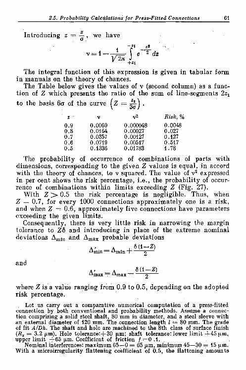
2.5. Probabilttu CalcuEattons for Press-Fitted Connections 61
5 Introducing z = - , we have u
The integral function of this expression is given in tabular form i n manuals on the theory of chances.
The Table below gives the values of v (second column) as a func- tion of Z which presents the ratio of the sum of line-segments 22,
to the basis 60 of the curve Z = - . ( z ' v v2 Risk, %
0.9 0.0069 0.000048 0.0048 0.8 0.0164 0.00027 0.027 0.7 0.0357 0.00127 0.127 0.6 0.0719 0.00517 0.517 0.5 0.1336 0.01783 1.78
The probability of occurrence of combinations of parts with dimensions, corresponding to the given Z values is equal, in accord with the theory of chances, to v squared. The value of v2 expressed i n per cent shows the risk percentage, i.e., the probability of occur- rence of combinations within limits exceeding Z (Fig. 27).
With 2 > 0.5 the risk percentage is negligible. Thus, when Z = 0.7, for every 1000 connections approximately one is a risk, and when Z = 0.6, approximately five connections have parameters exceeding the given limits.
Consequently, there is very little risk in narrowing the margin tolerance to Z6 and introducing in place of the extreme nominal deviations AmIn and A,,, probable deviations
and
where Z is a value ranging from 0.9 to 0.5, depending on the adopted risk percentage.
Let us carry out a comparative numerical computation of a press-fitted connection by both conventional and probability methods. Assume a connec- tion comprising a solid steel shaft, 80 mm in diameter, and a steel sleeve with an external diameter of 120 mm. The connection length I = 80 mm. The grade of fit AIDh. The shaft and hole are machined to the 8th class of surface finish (R, = 3.2 pm). Hole tolerance:+30 m; shaft tolerance: lower limit +45 ym, umer limit +65 um. Coefficient of kiction f =0 .I.
Nominal interferences: maximum 65-0 = 65 pm, minimum 45-30 = 15 pm. With a microirregularity flattening coefficient of 0.5, the flattening amounts

62 Chapter 2. Press-Fitted Connections
to 6.4 pm. The actual maximum interference is, thus, 65-6.4 = 58.6 pm, and the minimum, 15-6.4 = 8.6 pm.
For the probability computation assume that Z = 0.6 (risk percentage 1-2
is 0.517). The value -equals 0.2. Probable deviations of dimensions: hole - 2
Fig. 27. Risk percentage as a function of Z
minimum 0 + 30.0.2 = 6 pm, maximuim 30 - 30.0.2 = 24 pm, shaft-maxi- mum 65 - 20.0.2 = 61 pm, minimum 45 $- 20.0.2 = 49 pm. Probable inter- erences: maximum 61 - 6 =55 pm, min~mum 49 - 24 = 25 pm. Accounting for fthe microirregularity flattening the maximum interference is 55 - 6.4 = = 48.6 pm, and the minimum interference, 25 - 6.4 = 18.6 pm (Table 5).
As seen from Table 5 the probability computation gives more favourable characteristics which a t the same time are closer to the actual parameters of completed connections.
The normal distribution law is valid wherever a large number of occurrences is involved, and, hence, for mass production and with controlled operations a t that. Substantial deviations from this law occur in individual and small-lot production, attributable in the first instance to the small number of occurrences and, secondly, to certain specific features of the machining process. With individual production the operator involuntarily keeps to the lower hole toler-

2.5. Probability Calculations for Press-Fitted Connections 63
Table 5
Calculation Results for a Pressed Connection
ance limit and the upper limit for the shaft, orienting to the NO-GO side of gauges. Because of this the holes are made, on the average, closer to the minimum (nominal) size, while the shaft dimensions show a tendency toward the ma- ximum (upper) limit of toleran- ce. The grouping centres on the distribution curves are thereby shifted (Fig. 28) and the proba- bility of obtaining maximum interferences is thus increased.
An asymmetry of size distri- bution also periodically occurs in mass production with cont- rolled operations. As the cutting tools wear down, hole dimen- sions approach the minimum, and shaft dimensions, the maximum. Fig. 28. Distribution curves with The periodicity of this pheno- displaced grouping centre menon depends on operation ad- justment frequency and is absent only with automatic readjust- ment. To establish any regularities of the dispersion changes in a general form is difficult.
However i t is still necessary to note that any probability com- putation gives average figures of the expected size distribution over a long time interval and for large batches of products. The possibility
Characteristics
Maximum interference, ym Minimum interference, ym Press-fitting force (with maximum
interference), kgf Holding power (with minimum
interference): axial, Pa,, kgf Mtors, kgf .In
Stresses (with maximum interfe- rence):
in shaft, oi, kgf/mmz in hub, 02, kgf/mm2
Computation by
nominal values
58.6 8.6
8500
1250 50
8.6 15.3
probable values
48.6 18.6 7200
2750 110
7.1 12.7

64 Chapter 2. Press-Fitted Connections
.of a temporary crowding of low-probability size combinations is not excluded, .as a result of which comparatively large batches of defective connections will appear, although the mean level of risk related to very large batches will still remain within the computed limits.
All this restricts the practical value of the probability computa- tion technique.
When designing press-fitted connections it is better to keep within narrow boundaries such an interference as will ensure good working capacity of the connection without inducing high stresses in the mating components. With the existing systems of press fits, which are noted for their large deviation scatter, it is difficult to achieve. The selective assembly method is undesirable as i t complicates production. The general rule is to employ fits to the highest grades sf accuracy, in particular, those to the first grade of accuracy. However, this class of fits only covers a limited range of interferen- ces. Therefore it seems advisable to develop a single class of press f i ts with lower margin tolerances that would encompass the entire range of interferences necessary for the industry.
2.6. Press-Fitting with Heating or Cooling of Parts
The press-fitting force may reach substantial values, especially with great interferences and large surfaces of joint. This force pro- gressively increases as the part being press-fitted is forced deeper into the hole, reaching its maximum at the end of the procedure. The maximum press-fitting force may be determined from Eq. (2.2).
Let us find the force necessary to press a solid steel shaft (al = 0) with diameter d = 100 mm into a cast-iron hub 150 mm long and having external diameter d , = 165 mm (a , = 0.6) by the Dhl,, grade fit (A = 90 ym).
On the diagram shown in Fig. 21 we find that for a, = 0 and a , = 0.6, k, = 0.39. The unit pressure
The maximum press-fitting force is
P= kfF=2.8.0.1n.100-150= 13 000 kgf
The press-fitting procedure can be facilitated by heating the female part or cooling the male part, or else by practising both of these a t once. When press-fitting parts into large housing structures only the male component is cooled.
The heating temperature for the female part to have zero inter- ference

2.7. Pressed Connections with Electrodeposited Coatings 65
where t and to= heating temperature and workshop temperature, respectively
$ = relative interference in the joint .. a, = linear expansion coefficient of the female part
material d = diameter of t,he joint, mm
Similarly, when cooling the male component
where t' is the cooling temperature. I t should be remembered that a t subzero temperatures the linear
expansion coefficient a' decreases (see Fundamentals of Machine Design, Vol. 1 , Fig. 257).
Assume that in Eq. (2.1) A ,,,, w $D and that to = 20°C. Then, from Eqs. (2.24) and (2.25) one can find temperatures t (heating) and t' (cooling) required to obtain zero interference when assembling joints by different fits. For cast-iron and steel components ( a w z these temperatures are as follows:
Fits . . . . Dhll Dh and DMi DMs D t i z a DM3 DhZza Dh33 t , "C . . . 43 60 65 108 122 124 t ' , OC . . . -8 -30 -36 -40 -86 -90 -105 -110
Generally the cooling procedure is effected by using dry ice (evap- orates a t -80°C); or, for more intensive cooling, liquid nitrogen (-196OC1 and oxygen (-183°C).
I t must be borne in mind that heated components rapidly cool as they are being delivered from the furnace to the press. Furthermore, during the press- fitting operation the temperature of the heated hub quickly lowers due to its contact with the cold shaft. Therefore, due corrections must be introduced to compensate for the decrease of temperature during handling and press-fitting. In practice this implies that the components to be press-fitted must be overheat- ed by 30-50°C as compared with the calculated temperature.
The cooling temperature should also allow for the heating effect.
2.7. Pressed Connections with Electrodeposited Coatings
The strength of press-fitted connections (axial and torsional holding power) can significantly be increased by electroplating the contacting surfaces. Figure 29 shows the results of comparative tests of pressed connections assembled by the AIDh grade fit. The electrodeposited layer on the contacting surfaces was 0.01-0.02 mm thick. Two assembly procedures were used: one by means of a hyd- raulic press and the other with cooling the shaft in liquid nitrogen. In the latter case the radial clearance between the mating surfaces was 0.05 mm.

66 Chanter 2. Press-Fitted Connecttons
A connection without coating assembled in a hydraulic press (without shaft cooling) was used as a reference specimen, its axial holding power P o being taken as the unit of comparison.
From the diagram i t is seen that electroplating sharply (by 2-4.5 times) enhances the connection strength, and that the assembly with cooling the shaft assures a much higher connection strength than
Fig. 29. Relative strength of pressed connections with de osited coatings. Blackened columns indicate assemblv with shaft coolinrr. while iachured columns are for asscmbl in a press. The strehgth of a pressed cinnection without coating
and assembred in a press is taken as unity (after G. A. Bohrovnikos)
the press-fitting assembly. For uncoated connections assembled with cooling the joint strength is doubled, and for connections with soft coatings (Cd, Cu, Zn), improved by 20-30% in comparison with the assembly in a press.
The strength of connections with hard coatings (Ni, Cr) and assembled with cooling is worse than that of the same connections assembled in a press.
The greater strength of connections with electroplated coatings is probably due to the occurrence of strong molecular bonds a t the joint surfaces. The pro- longed dwell under the high ressure existing on the contacting surfaces cause? a diffusion process whereby tEe atoms of the base and coating metals mutually penetrate each other, thus forming some intermediate structure. In other words, a "cold welding'' seems to occur. As for the rather high (approaching unity) values of t e coefficient of friction (see the right-hand ordinate of the diagram in Fig. 29), this can readily be explained. The friction coefficient concept in its classical mechanical interpretation in these conditions is no longer valid: the value of the friction coefficient here shows the shear resistance

2.8. Design of Pressed Connections 67
of the intermediate layer associated with the base and plated metals and not, as is usual, the resistance to the displacement of one surface relative to another.
The lower ,strength of connections assembled with the aid of a press is attri- buted to the fact that the ridges of surface microirregularities are flattened and/or cut away. During the assembly with cooling the ridges remain intact and after heating penetrate the valleys in the mating surface, thus adding to the connection strength.
Joints with soft electroplating are disassembled without damage to the surfaces, but when disassembling connections with hard coatings, scores, cracks and deep tears in the base metal are observed, sometimes over considerable areas of the contracting surfaces, due to which reassembly is difficult or even becomes impossible.
The situation is aggravated by the fact that hard electroplating lowers the fatigue strength of the joint.
Due to all these reasons preference should be given to soft coatings. The application of soft coatings in conjunction with the assembly
with cooling allows the connection strength to be improved 3-4 times as compared with that of the press-fitted connections without coat- ings. Thus, it becomes possible, while maintaining the given joint strength, to employ smaller interferences, reducing, in this way, the tensile stresses in the female part and compressive stresses in the male part. In addition, the electrodeposited coatings protect the fitted surfaces against corrosion and eliminate the "welding" of surfaces subjected to cyclic loads.
The strength of pressed connections can seemingly be improved by metalli- zation and thermodiffusion saturation (e.g., by tt~ermodiffusion zinc plating) of fitting surfaces.
Still further stren thening of pressed connections can probably be attained by depositing dissimfar coatings upon the joint surfaces, for instance, a zinc coating on one surface and a copper one on the other. From the atomic diffusion of the two metals so;ne intermediate structures can be expected in the contact zone, possessing higher strength than homogeneous platings (e.g., brass-type alloys when zinc and copper deposits are combined).
2.8. Design of Pressed Connections The specific feature of pressed connections is that their joint
surfaces are already prestressed by interference forces prior to the application of working loads, subjecting the female part to a biaxial tension which is unfavourable from the strength viewpoint. When adding the prestresses to the working stresses, their resultant may exceed the yield limit of the material and cause connection failure.
Moreover, formal calculations of press-fitted joints, based on the assumption of constant cross-sections throughout the entire part length where the end conditions can be ignored does not express true stress values. In practice the strength of a joint strongly depends on the shape of the female and male parts. Uneven rigidity of parts (stepped shafts, hubs with disks, etc.) causes an unequal distribution

68 Chapter 2. Press-Fitted Connecttons
of contact pressures and stresses over the connection's length. Sharp stress gradients arise a t the joint edges.
Formal calculation, even with high safety margins does not always ;issure a reliable connection. The more so if one takes into account, that the magnitude and distribution of working stresses throughout the part cross-section and their relationships with prestresses remain rnost.1~ uncertain, especially in joints subjected to cyclic stresses. Therefore, regardless of computation results all constructive measures to strengthen pressed connections must be taken.
In order to enhance the strength and reliability of pressed con- nections i t is advisable to:
enlarge the diameter and increase length of connections so that unit pressure upon contacting surfaces is reduced;
( a ) ~ b ) I C I ( d l (e l If) Fig. 30. Lead-in chamfers and recesses in pressed connections
select interference values within narrow magrins, making use of more accurate fits;
avoid sharp changes in cross-sections of the connected parts over their contact areas (areas close to these parts), thus preventing abrupt stress relations;
improve contact surfaces by appropriate heat treatment (e.g., low temper hardening, induction hardening, etc.) or strengthen them by mechanical hardening (shot blasting, rolling of shafts, rolling out or burnishing of holes);
use assembly technique in which the female part is heated or the male part is cooled;
electroplate contacting surfaces, using soft metals (Zn, Cu, Cd). The reliability of pressed connections depends greatly on correct
assembly. To facilitate the press-fitting procedure leading chamfers should
be provided on the shaft and in the hole. The chamfers should be made a t 45O (Fig. 30a) or, better, a t 20-30' (Fig. 30b, c). If great interferences are expected, the shaft must have more gradual cham- fers of 5-10' (Fig. 30d). The chamfer leading diameter d is made 0.1-0.2 mm less than the hole diameter do.
Occasionally the shaft or the hole is designed with leading cylin- drical collars having an aligning fit, e.g., a slide fit (Fig. 30e, fj.

2.8. Design of Pressed Connections 69
The location of the aligning collar in the hole (Fig. 30f) necessitates the employment of the basic shaft system.
I t is very 'important to prevent seizure and distortion of the joined parts, which impede the press-fitting process or may even spoil the connection altogether.
Bush-type thin-walled components are guided when I~eing press- fitted by means of a centring mandrel (Fig. 31a). Figure 31b shows
Fig. 31. Methods for press-fitting Fig. 32. Methods for axial fixing of thin-walled bushes parts when press-fitting
a method of press-fitting used for through holes. A bush is mounted upon a screwed-on mandrel with a pilot shank I, introduced in to the hole with a slide fit. After the press-fitting is over, the mandrel is screwed off.
Axial position of the part is fixed by pressing the part home t o a stop shoulder (Fig. 32a, b), a hole step (Fig. 32c), flush with the hole edge (Fig. 32d), or until the hole edge i s flush with a shoulder on the part (Fig. 32e). Plain parts can be fixed in any position b y means of distance rings I placed under the press plunger (Fig. 32f). A typical error made when designing pressed connections is the
insufficient length of the joint collar. The connection with a short collar quickly fails due to the crushing of the contact surfaces under the effect of working loads. Examples of wrong and correctly designed pressed connections are illustrated in Fig. 33.
For general purposes and rough determination of the minimum length of pressed connections the following formula may be used:

70 Chapter 2. Press-Fitted Connections
where I, , = length of the press-fitted portion (less chamfers), mm d = connection diameter, mm
A graph based on Eq. (2.26) is plotted in Fig. 34. If the connection is subjected to high bending or shearing loads,
especially alternating ones, or if i t is necessary to assure a precise
connecting
' (a) 2 ' (4 2
Fig. 33. Pressed connections: rod end1 (b) press-fitting cup-shaped component on shaft;
correct 1 - wrong;
positioning and sound anchoring of the press-fitted component (e.g., bed columns), the length of the press-fitted portion is con- siderably increased (1 = 1.5-2d).
Avoid, whenever possible, press-fitting in blind holes, because the latter are more difficult to machine and hamper dismantling.
Should the fitting in blind holes be unavoidable, i t is necessary to assure free exit of air during the press-fitting process. Compression of air when pressing, accompanied by increase of i t s specific volume, can break the female part, particularly when i t is thin-walled or made of a less strong material (e.g., light alloys). Air is vented via holes (Fig. 35a, c) or grooves (Fig. 35b).
Never press-fit components through two sections with holes of the same diameter (Fig. 36a): while passing the component through the first section (the upper in the Figure) a misalignment frequently occurs, that impedes the introduction of the male part into the second section. In addition, scores may form on the surfaces of the mating parts.
Under such circumstances each section should have holes of dif- ferent diameters (Fig. 36b). The axial dimensions of the connection must be so designed that the part enters the second section first to a depth m = 2-3 mm (Fig. 36c), thus obtaining a definite direction, and only after that enters the first section.
I t would be wrong to force a bush into a casing as illustrated in Fig. 36d. Here, in order to reduce the amount of precision machining,

2.8. Design of Pressed Connections 7 1
the bore has two short joint collars. The error is that both collars have the same diameter. Besides, the distortion of the bush on the fitting areas is inevitable.
Fig. 34. hl of joint
If strict linearity of the hole walls is important, the bush then must be reamed after the assembly, or fitted over its complete length Fig. 36e) or, at least, over a major portion of i ts length (Fig. 36f).
Fig. 35. Air evac~~ation when press-fitting parts in blind holes
Female components must be given ample rigidity to avoid their deformation during the forcing procedure.
In the case shown in Fig. 36g the upper eye will deflect, thereby making impossible the press-fitting into the lower eye. If for some

7 2 Chapter 2. Press-Fitted Connections
design considerations the hole walls cannot be made thick enough, then i t is absolutely necessary to employ some stiffening device during the press-fitting procedure. The simplest device is a horse- shoe-shaped spacer 1 inserted in-between the eyes.
Fig. 36. Press-fitted connections
The employment of such a spacer must be thought of beforehand by designing the distance between the eyes to suit one common spacer which can be used for a series of parts.
The female and male parts should be of uniform rigidity in the radial direction. Local weakenings, cut-outs, etc., should be avoided.
Fig. 37. Press-fitting a bush
In the case depicted in Fig. 37a press-fitting is impeded by the una- voidable deflection of the bush toward the cut-out. Furthermore, a t the cut-out area the bush will be given additional deflection due to the unilateral radial interference. The situation can be improved

2.8. Design of Pressed Connections 73
slightly if the bush is press-fitted into two sections located in the non-cut-out areas of the hub (Fig. 37b). I n this case i t is better to assemble the bush by a location fit and fasten i t in position with bolts (Fig. 37c).
Press-fitting is inapplicable when the female or male part has through-cuts extending to the end face (Fig. 37 d). If cut-outs cannot be eliminated the only reason- able way is to employ a location fit.
Occasionally it is necessary t o position press-fitted parts a t a certain angular attitude. Such, for example, i s the case when press-fitting a keyed shaft into i t s hub. The alignment of the key with its slot is assured if the leading end of the shaft (Fig. 38a) has a location or free fit over length I which exceeds the dis- Fig. 38. Fitting a keyed in tance h of the key from the shaft a hub end face. The key is first intro- duced into the keyslot and after that the shaft is press-fitted.
Another method: the key protrudes out from the shaft to a distance h which is sufficient to assure the shaft location in the keyslot before the press-fitting procedure begins (Fig. 38b).
The best practice is to assemble the connection with previously heated hub or cooled shaft in order to obtain a clearance in the
Fig. 39. Press-fitting cams in a disk
connection. The angular location of the shaft in the hole will then present no difficulties.
Lobed cams with given edge setting angles (Fig. 39) should be pressed in place by means of a guiding adapter having radial cut- outs for the cam lobes, which is located from the central hole in the disk. The possibility of applying such an adapter must be considered in designing.

74 Chapter 2. Press-Fitted Connections
Figure 39a shows an incorrect design: large shank a t the cam root prevents the cam passing through cut-outs in the adapter. I n alter- native, presented in Fig. 39b, the shank size is reduced but the dis- tance m between the cam edges is less than the fitting diameter d, therefore, the cut-outs in the adapter must have formed contours. In the correctly designed version, Fig. 39c (m > d) a simple adapter can ensure a correct cam orientation.
(a) Pressing-Out
When designing a pressed connections the possibility of i ts disas- sembly must be considered. Parts to be pressed out must have sur-
faces (preferably flat) which can rest during the pressing- out upon solid plates or bush- es.
A poor design is illustrated in Fig, 40a. Here, the pulley press-fitted upon the hollow shaft has to rest during the pressing-out procedure on i ts conically-shaped portion, which complicates the shape
Fig. 40. Pressing-out conditions of the bearing plate intended to receive the pulley during
the pressing-out. The sharp edges of the shaft are unsuitable for resting against the end face of the press ram.
I n the design shown in Fig. 40b the pulley has a bearing cylindrical web; the shaft end face is made flat. However, in the course of pres- sing-out excessive stresses may arise in the pulley disk, particularly if i t has a large diameter.
Therefore i t is better to position bearing surfaces close to the hub (Fig. 40c).
The pressing-out force reaches its peak value (rather high) a t the initial moment, when the friction of rest is being overcome. After this the pressing-out force decreases because the friction of rest concedes to that of motion, while the length of the press-fitted section continuously decreases as the female part moves off the shaft.
Over the last few years hydraulic systems are used in which pres- surized oil, whose pressure exceeds the contact pressure (of the order of up to several hundred atmospheres) is admitted into an annular recess in the joint surface through a hole in the shaft (Fig. 41a) or in the hub (Fig. 41b) . The pressure of oil produces elastic radial deformation of the parts to be pressed out. At the same t ime the

2.9. Conical Fits 75
presence of oil minimizes friction during pressing-out. Moreover, the layer of oil, penetrating into a circular slot in-between the parts
Fig. 41. Pressing-out hydraulically Fig. 42. Pressing-out a bush hydraulically
due to capillary forces, acts as a wedge, which greatly facilitates the pressing-out.
When pressing-out conical joints hydraulically, no mechanical force is required to force the female part off the shaft.
Figure 42 shows how a bush can be pressed-out hydraulically from a blind hole. The bush space is filled up with oil and the bush forced out by a sharp blow on plunger I.
2.9. Conical Fita Alongside cylindrical press fits extensive use is made of conical
press fits (Fig. 43). Tapers K usually range from 1 : 50 to 1 : 100.
(b) (4 Fig. 43. Conical pressed connections
The required connection interference is obtained by applying a defi- nite force when press-fitting the shaft in place. The force is rigorously controlled since the slow taper easily causes excessive radial inter- ferences.

76 Chanter 2. Press-Fitted Connections
The press-fitting force may be determined from the relation P = Fk (sin a + f )
where F = joint surface area, mma k = unit pressure on the contacting surfaces, kgf/mma a = cone generatrix angle (Fig. 43a) f = coefficient of friction between the mating surfaces
As the magnitude of sin a is very small in comparison with f , i t can be omitted. Then
P = Fkf
As the values 01 D and d are rather close, the joint surface area (i.e., the curved surface of the truncated cone) will be
Finally
Another method is forcing the male component ~ n t o the female one to a definite depth h (Fig. 43b), counting from 'the moment the mating surfaces come into close contact. The amount of h (axial interference) can be found from the relation
where K = 2tan a = taper A = required diametral interference in the joint, ym
RZ1 and R,, = mean roughness height of the shaft and bore, respectively
cp = flattening coefficient of microirregularities
Let us find the magnitude of h for a pressed connection when D= 50 mm and K = 1 : 50.
Assume that 6.3 pm (7th class of surface finish) and R,, = 10 pm (6th class of surface finlsh). Let the interference be 37 pm, which corresponds to the mean irterference in the case of the Dh grade fit for a diameter of 50 mm.
From Eq. (2.28)
h = lo-3 37+ 16'3= 2.6 mm 0.02
The h value is held either to the difference between the positions of marks on the shaft prior to and after the press-fitting or by pres- sing the shaft until i t rests against a stop shoulder positioned a t distance h from the hole edge (see Fig. 43b). The latter method requir- es a selective assembly of parts, for inevitable inaccuracies in the joint diameters cause substantial deviations in the dimension h due to the slow taper.

2.10. Serrated Connections 77
Often press-fitting is effected by a calibrated blow, i.e., by drop- ping a weight I (Fig. 43c) from a certain height. The mass of the weight and the dropping height are found experimentally or calculated by a design subsidence value h obtained when press-fitting a reference shaft into a reference hole by a blow.
A still better fitting method is that with a preliminary heating of the female part or cooling of the male part, because in this case the male part is introduced into the female one either vithout any or with a very slight effort. After the female part has cooled (or the male part has warmed) a tight interference fit occurs in the joint. The magnitude of interference (and, for a known interference, the required heating temperature) may be found from Eqs. (2.18) to (2.20).
2.10. Serrated Connections
In some instances, to improve the torsional holding power of pres- sed connections, the shafts are serrated, i.e., given longitudinal grooves having a triangular cross-section (Fig. 44). The external diameter of serrations is made 0.05-0.2 mm greater than the A -A - hole diameter. During press-fit- ting the sharp ridges of the ser- rations cut into the material of the female part, thus ensuring a strong connection between the shaft and the part.
Generally serrations are pro- duced by cold rolling. The shaft surface must have a hardness of not below 35-40 Rc and the hole surface 10-15 units lower than that.
Serrations are formed either throughout the entire length of the joint surface (Fig. 44a) or (which is more preferable) over a limited section on the side fur- Fig. 44. Serrated connections
thest from the press-fitting direc- tion (Fig. 44b). The latter technique ensures more accurate alignm- ent. Serrated connections allow lower interferences to be used (we mean the interferences on plain sections) than in conventional pressed joints. Small-diameter rods (d < 15 mm) are often intro- duced into drilled holes without any interference, relying on the strength of connection between serrations and the bore.

78 Chanter 2. Press-Fitted Connecttons
Serration is only practicable for permanent connections, since the repeated installation of serrated shafts weakens the connection because the first assembly destroys the hole surface.
2.11. Glued Connections In many cases press-fitted connections can successfully be replaced
by glued connections whose strength is comparable with that of the former.
The axial holding power of pressed and glued connections P = kFf and d P g l = FT, respectively, and their torsional holding power, M = k F j - and 2
M g l = F ~ 2 , where k is the pressure on the joint surfaces and r, the shear strength 2 of the glue layer.
Equating P = P g l and M = LVglr gives a general equistrength relationship
which defines the unit pressure k in pressed connections equivalent (in terms of strength) to glued joints. For epoxy base glues r = 2-3 kgfImm2. Calculating
2 by the lower limit, we have k = -. With f = 0.15, k =- 13.5 kgflmmz.
f J
This value of k corresponds to moderate interference fits of grades D h l l , Dh2, and Dh.
The advantage of glued connections is that they do not cause stresses in the connected parts. They exclude the need for pressing, or heating, or cooling and considerably facilitate the assembly pro- cedure. For thermosetting glues, however, they must be held a t a temperature of 150°C for approximately 2 hours.
Glued connections are assembled by slide or transition fits. In pressing-out the glue film is destroyed. For the repeated assembly i t i s necessary to wash off the traces of the old film with a solvent and then apply a fresh layer of glue.
Glued connections remain stable a t temperatures up to 200°C, which limits their field of application. Under the effect of cyclic loads, even in cold connections there may develop local seats of increased heat liberation which destroy the glue film.

Chapter 3
Centring Connections
Cylindrical surfaces are generally centred by slide (S) of transi- tion [push (P), wringing (W) and tight (T)] fits. Occasionally easy side (Se) fits are also employed.
Figure 45 shows the mean values of clearances and interferences for various grades of fits as a function of the centring surface dia- meter.
With slide fits the clearan- 4n~m,,pcm ce in the joint is zero only un- 120 der extreme conditions when the female and male surfaces are made to the nominal size. I n the majority of cases the go connections have some clearan- ce reaching significant val- 6o ues for the low accuracy clas- ses. Consequently, slide fits 40 cannot ensure accurate cen- tring.
Clearances can also occur 20
with the push fits (P). The wringing fits ( W) are without clearance and should be used when accurate alignment is -w necessary. Tight fits (T) are 100 200 300 400 R, mm obtained with insignificant in- terferences in the connection. Fig. 45. Mean clearances and interferen-
Tight and wringing fi ts en- ces A,,, for different fits as a function of centring surface diameter D
sure accurate alignment with- out complicating~ssembly and disassembly if the centring surfaces have short lengths (e.g., collar flanges). Parts with long centring surfaces (hubs) are bet- ter assembled by slide and push fits, if the requirements as to high alignment accuracy are not imperative and there is no danger of the joint surfacs being damaged under the action of loads.

80 Chanter 3. Centring Connections
Average clearance values depend not only upon the grade of fit, but on the grade of accuracy as well. The easy slide fit to the 1st grade of accuracy (Sel) is practically equivalent to the slide f i t (8) to the second grade of accuracy (disregarding the narrower margin tolerance); the S1 fit is equivalent to the P fit, and the Se fit, to the S,, fit.
When nominating fits due consideration must be given to the temperature conditions in which the joint is expected to operate. The original (cold) fit may sharply change during heating, particu- larly when the female and male components are made of materials with different linear expansion coefficients. I n such conditions heat calculations are obligatory.
If during heating the female component expands more than the male part, tighter fits should be nominated (P, W and T), and if the male part expands more, free fits (S, Se and even R) should be preferred.
Let the diameter of the centring surface be D = 200 mm. The female part is made of a light alloy (a, = 24-10-6), and the male part, of steel (a, = = 11 . lo-6) . The working temperature of the connection is 100°C. The connec- tion is assembled by the S,, grade of fit (diametral clearance A = 0 to 0.12 mm).
After heating the clearance becomes
Obviously, the centring accuracy is disturbed. A tight fit will somewhat impove the situation. The maximum clearance with this grade of fit amounts to 0.056 mm, and the maximum interference, 0.064 mm. Consequently, after heat- ing the resultant clearance in the joint will range from 0.26 - 0.064 =0.196 mm to 0.26 + 0.056 = 0.316 mm.
With larger radial dimensions of the connection and higher working tempera- tures the original fit often alters to such a degree that it is impossible to centre the cylindrical surfaces, and a temperature-independent centring must be used (see Fundamentals of Machine Design, Vol. 1, Section 7.3, p. 472).
3.1. Design Rules
To enhance the alignment accuracy and reduce the effects of tem- perature-induced deformations, it is undoubtedly better to centre parts from the smallest possible diameter. Ways of reducing the centring diameters are illustrated in Figs. 46 and 47.
The screwed bracket (Fig. 468-f) is an example. When the centring is accomplished from a large diameter (Fig. a d ) equal to, say, 200 mm, the maximum clearance with the S,, grade of fit will be 0.12 mm, but when centring from the minimum diameter (Fig. 46f) this clearance decreases to 0.037 mm, i.e., approximately thrice. The centring is sharply improved and becomes practically tempera- ture-independent.

3.1. Design Rules 81
When] centring franged parts a sufficiently long centring shoulder should be provided, allowing for the leading chamfers in the hole
Fig. 46. Reduction of centring diameter (a-c) gear rim; (d-f) bolted bracket
and on the male part, as well as gaskets, that considerably decrease the actual length of the centring surfaces.
Shoulder height H is chosen so as to ensure positive centring from section h (Fig. 48)
where c = length of the leading chamfers with the most unfa- vourable combination of manufacturing deviations
s = gasket thickness (in compressed state) Ac = plus deviation of the leading chamfer dimensions from
the nominal AH = minus deviation of the centring shoulder height from
the nominal The dimensions of the centring section h and chamfers (in the
hole and on the male part) for mass produced connections may be taken as follows:
Diameter of cen- tring surface, mm . . . . . up to 100 100-200 200-300 300-500 over 500
h , m m . . . . . 3-4 4-5 5-6 6-7 7-8 Chamfers . . . . 0.5-45" 0.8.45O 1.45" 1.5.45" 2.45O

82 Chapter 3. Centring Connections
The shoulder height H is practically determined from the rela- tion H m 0.5 l / B l where D is the centring surface diameter;(provid- ed that ordinary 0.1-0.2 mm thick gaskets are used).
Fig. 47. Reduction of centring diameter in connections of housing-type com- ponents
In housing-type components (Fig. 49) the centring surfaces should be made in the form of holes which can readily be machined on boring machines (Fig. 49d, e). The observance of this rule is particu-
larly important when the centring is ac- complished from co-axial surfaces position- ed on different sides of the housing (Fig. 49f, g). The design illustrated in Fig. 49f is extremely poor as the centring shoulders on such a housing have to be machined in different tool settings and proper alignment can be assured only with the aid of spe- cial attachments. I n the correctly designed version presented in Fig. 49g the centring surfaces of the housing can be through- machined in a single tool setting, thus ensuring good alignment.
Fig. 48. Determination of Simultaneous centring from two surfaces centring shoulder height (Fig. 50a) must be avoided whenever possib-
le: the centring must be accomplished from one surface only, leaving a positive cearance s on the other surface (Fig. 50b1 c).
I n the flange unit shown in Fig. 50d the centring of splined flange I from the shaft is not only superfluous (the centring being effected

Fig. 49. Positions of centring shoulders (a), (d) and (fl wrong; (b), (c), (e) and (g) correct
Fig. 50. Elimination of double centring

84 Chapter 3. Centring Connections
by the splines themselves) but harmful since i t hinders the correct clearance-free fitting of the splines. In the correctly designed ver- sion pictured in Fig. 50e clearance s is provided between the compo- nents.
The next Fig. 50f shows an incorrect valve design with a guide shank. The small clearance between the shank and the bore prevents the accurate seating of the valve cone. In a better alternative (Fig. 50g) a:greater clearance is given.
Figure 50h presents a wrongly designed assembly of a ball bearing inside a sleeve with two centring surfaces serving simultaneously
Fig. 51. Heducing the number of centring surfaces
as a sealing bush with split spring rings. Correct alternatives are illustrated in Fig. 50i, j.
In units consisting of several concentrically arranged components the number of centring surfaces should be reduced to the minimum, since the accuracy of the unit as a whole is considerably impaired by the cumulative error introduced by each centring surface, which is the greater, the larger the number of the surfaces.
In the design shown in Fig. 51a, an antifriction bearing is mounted in two intermediate bushes. Apart from the clearances between the rolling bodies and races, there are four centring surfaces. Reduc- ing the number of the centring surfaces down to two (Fig. 51b) impro- ves centring accuracy approximately twice.
When centring from a cylindrical pin (Fig. 51c) pressed in member 1 and fitted by a slide fit in the hole of member 2, the centring errors from the two surfaces are summed. In units requiring accurate centr- ing i t is necessary either to machine the centring surface of the pin concentrically to the precision surfaces on the part to be centred, after the pin is pressed in, or the centring pin must be made directly on the part in question (Fig. 51d).
Figure 51e depicts the case of an irrational centring from two sur- faces: surface m on the shaft, and surface n on a detachable disk. The centring from the surface n is either fictitious (if the disk is fitted on the centring part with a clearance) or disturbs the centring from the surface m (if the disk is fitted on the shaft with an interfe- rence). I t is better to centre the part from the shaft, the disk being freely mounted (Fig. 51f).

As a rule, cylindrical surfaces must be centred from a full circum- ference. Small recesses, however, hardly affect the alignment accu- racy. I n some instances, when necessary for the design,-parts may
Fig. 52. Centring from incomplete cylindrical surfaces
be centred from incomplete circumferences, if the centring arc is not less than 270° (Fig. 52) and the part being centred has ample rigidity in the radial direction. In practice they often implement
Fig. 53. Elimination of superfluous centring (a-d) incorrect designs; (e) correct design
centring from teeth (Fig. 52b), splines (Fig. 52c) or even from indi- vidual lugs, when the latter are a t least three in number and are spaced symmetrically over a circumference.
A common mistake of young designers is to introduce centring where for operation i t is superfluous and can be dispensed with. For instance, for the intermediate mounting of an antifriction bear- ing the centring of the lateral cheeks (Fig. 53a-d) is actually not necessary. Here i t is sufficient to fix the cheeks in radial direction by means of fastening bolts (Fig. 53e), this considerably simplifying the manufacture.

Chapter 4
Screwed Connections
The principal requirement for correct functioning of screwed connections is that the threads must be free from bending and shear- ing stresses.
A bolt loosely mounted in the hdes of the clamped parts and subjected to the action of transverse forces (Fig. 54a) deforms. With a full elimination of clearance at bolt sections near the joint more shear stresses arise. Furthermore, the bolt is sub'ected to tension due to which it elongates under the displace- ment of the ulied part. Allithese stresses are added to the tensile stresses induc- ed in the boft during the preliminary tightening. As a result, in the bolt body
Fig. 54. Flexure of threaded parts
a complex state of stress occurs, produced by the simultaneous action of bend- ing, shearing and tension forces, and the bolt's strength abruptly drops.
A screwed-in bolt has still worse working conditions (Fig. 54b) when in its critical section (close to the joint plane) a thread is cut, appearing as a very strong stress concentrator. Most unfavourable is the case of the bending of a stud screwed home in a hole (Fig. 54c). Here high tensile stresses arise in the critical section, comprising the prestresses and stresses produced as the stud is tightened against the hole bottom. As in the previous case, here the stress concentration occurs in the section where the thread comes to the critical sec- tion plane.
Also unfavourable are the working conditions for the material of the thread- ed holes of tightened components. The transverse forces, acting a t the joint, wedge out the threeds of the screwed hole, roducing higher local bearing stres- ses which in time weaken the thread and toosen the fit of the screwed stem, particularly under alternating loads.
The problem of strengthening tightened connections consists in the elimination of the complex stressed state in the fastening ele- ments and assure conditions in which these elements would operate only in tension when under the influence of preliminary tightening

Chapter 4. Screwed Connections 87
and working forces. Transverse acting forces must be taken up by additional shear load-carrying elements.
Let us consider the case of a cantilevered rod, screwed in a hous- ing (Fig. 55a). Design 1 is obviously unsatisfactory, because the maximum bending moment from the transverse force P is in the weakened threaded portion. High stresses a t the imbedment point inherent in the cantilever make the rod bend and crushes the threads in the hole and on the rod.
Provision of a shoulder in the tightening area (version 2) helps little, since the shoulder thrust face is nearly parallel to the direc- tion of bending displacement and the deformation is resisted only by the friction forces arising a t the thrust face when tightening.
In more correct designs 3 and 4 the rod has a cylindrical or tapered section which closely fits the housing hole and efficiently impedes transverse strains and rod displacement. Since i t is rather difficult to assure strict alignment of the threaded and plain sections, the screwed end must have clearance.
The best are designs 5 and 6 which have a cylindrical or tapered fitting section in the housing. I n this case the threads are completely relieved from bending and take up only the tightening tension.
Figure 55b illustrates various methods of fixing a cast stand loaded with a transverse force to a housing. Version 7 is absolutely incorrect: the fastening stud is subjected to bending from the transverse force. Version 8 is hardly better: here the stand is aligned by the plain stud portion. I n the improved version 9 the stud has a centring cy- linder which closely fits into the holes of the housing and stand. I n design 10 shearing forces are taken up by check pins and in design 11 by the stand centring shoulder.
Illustrated in Fig. 55c are various methods of taking up shearing stresses in a counterbalance unit joint loaded with a centrifugal force, and in Fig. 55d, in a flanged connection transmitting a torque. Designs 12 and 17 are wrong, and the rest to a more or less degree provide correct operating conditions for bolts.
Bending of bolts is often the result of their incorrect positioning relative to the acting loads (Fig. 55e). The bracket in design 22 has two errors: lack of an element taking up the shear stresses and the bending of the bolt stems due to the off-centre application of the axial load. Under the action of force P the bracket tends to turn about point A . With the relationships presented in the Figure, the
force acting upon each bolt is N = $ = 1.7P. The bolt is subjected
to bending by a moment M = y, where d is the diameter of the bolt head.
With the flange turned through 90' (version 23) the load upon the bolt becomes practically central (owing to the extension of arm b ) .

Fig. 55. Relieving threaded parts from flexure and shear
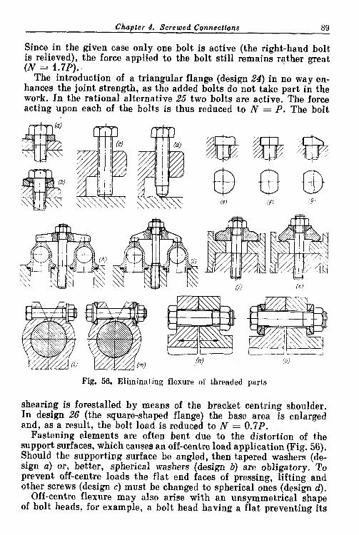
Chapter 4. Screwed Connecttons 89
Since in the given case only one bolt is active (the right-hand bolt is relieved), the force applied to the bolt still remains rather great (N = 1.7PI.. ' The introduction of a triangular flange (design 24) in no way en- hances the joint strength, as the added bolts do not take part in the work. In the rational alternative 25 two bolts are active. The force acting upon each of the bolts is thus reduced to N = P. The bolt
Fig. 56. Eliminating flexure of threaded parts
shearing is forestalled by means of the bracket centring shoulder. In design 26 (the square-shaped flange) the base area is enlarged and, as a result, the bolt load is reduced to N = 0.7P.
Fastening elements are often bent due to the distortion of the support surfaces, which causes an off-centre load application (Fig. 56). Should the supporting surface be angled, then tapered washers (de- sign a) or, better, spherical washers (design b) are obligatory. To prevent off-centre loads the flat end faces of pressing, lifting and other screws (design c) must be changed to spherical ones (design d).
Off-centre flexure may also arise with an unsymmetrical shape of bolt heads, for example, a bolt head having a flat preventing its

90 Chaoter 4. Screwed Connections
rotation when tightening (version e). The flexure here can be eli- minated by machining flats on two sides (alternative f ) or by decreas- ing the head rigidity in the area opposite to the flat (version g).
Self-alignment of fastening elements is a radical means to avoid flexure. I n design h (clamping down adjacent angles of hydraulic communication system with the aid of a crossbar) distortion of the crossbar is inevitable, also inevitable are bending of the bolt and non-uniform tightening of the angles. These defects are eliminated in version i by providing a self-aligning crossbar.
Wrong j and correct k alternatives of clamping the flanges of adjacent cylinders to the crankcase are shown in Fig. 56.
Flexure may also arise as a result of elastic strains emerging in the tightened parts. When tightening clamp-type connection 1 the ends of the clamps distort and the load becomes eccentric. In design m the flexure of the clamping bolt is prevented by the intro- duction of spherically shaped washers.
In all connections where the bolts are displaced from the plane of acting forces flexure is inevitable (e.g., in flanged connections n loaded by the internal pressure). Self-aligning bolts o are recommend- ed for heavily loaded critical connections.
4.1. Longitudinal and Transverse Location of Parts in Screwed Connections
Screwed connections do not ensure accurate mutual location of the clamped parts.
Generally, fastening bolts and studs are introduced into their holes with some clearance whose amount is dependent on the number and spacing, as well as accuracy of centre-to-centre distances, of holes, and on the average varies from 0.5 to 1 mm. If such a clearance is absent, the assembly becomes impossible due to certain mismatching of mated holes in the parts to be coupled and the displacement of holes one relative to another in each part, a fact inevitable in practice.
To ensure accurate mutual location of parts i t is necessary to introduce certain locating elements. The methods of such a location are illustrated by an assembly example of a bearing cover to a hous- ing (Fig. 57). Often the location is accomplished from longitudinal shoulders (Fig. 57a-c) machined in the cover or the housing, which are tightly fitted in corresponding slots.
The design alternative with a locating lug (Fig. 5 7 4 is not suit- able because i t require. a close contact over four surfaces a t once. The location with fitted-in prismatic keys (Fig. 57e) is also not recom- mended.
The cylindrical shape of the centring shoulder (Fig. 57f) facilita- tes accurate manufacture of the shoulder and i ts housing seat and ensures longitudinal and transverse cover location. The cover, however, is not prevented from turning about the line of joint.

4.1. Location o f Parts tn Screwed Connections 91
The design seems to be more advantageous for single bearings; for series-arranged bearings it is better to employ longitudinal shoul- ders and slots machined in a single tool setting.
Fig. 57. Methods of fixing bearing caps to housings
Occasionally the cover is located by means of endwise splines having a triangular section (Fig. 57g) and; produced by outside broach- ing. This method is technically possible (provided the necessary equipment is available) and enables a sturdy joint to be obtained.

92 Chapter 4. Screwed Connections
Higher robustness is assured by mounting the covers in lengthwise housing recesses (Fig. 57h, i).
The methods illustrated in Fig. 57a-i ensure a transverse location of the cover. If the bearing has to take up axial loads, a lengthwise location is necessary to assure the matching of the cap and housing end faces. Such a location is accomplished by means of cylindrical collars on studs (Fig. 57j), insert-type cups (Fig. 57k) or dowel pins (Fig. 571).
Detachable taper locating pins (Fig. 57m) ensure a more accurate location, but are much more difficult to produce and assemble. Moreover, they have to be prevented from falling out. Location by means of lengthwise dowel pins (Fig. 57n) is practicable only when the bearing end face can be directly drilled and reamed. This method cannot provide for the taking up of longitudinal loads.
The design in Fig. 570 shows a unique method of fastening the cover with the aid of taper pins press-fitted into a row of lugs milled in the housing and cover. Lengthwise location is effected by fitting closely the lugs of the cover (or a pair of lugs) inside the receiving slots of the housing.
Still another method is the location by means of lengthwise pins (Fig. 57p) introduced into the holes machined in the vertical joint surfaces between the cover and housing. The system is tightened
, transversely by bolts. If i t is impossible to drill or ream directly in the bearing end face, broached triangular-section splines must replace the pins.
4.2. Centring in Screwed C o ~ e c t i o n s
Screwed connections of conventional accuracy do not ensure pre- cise centring due to the practically unavoidable run-out of the thread pitch diameter, as well as thread clearances. Exceptions from this rule, however, are encountered occasionally when dealing with precision centring threads-mostly large trapezoidal threads pro- duced by milling and grinding.
With the usual manufacturing accuracy the centring from the threads is not permitted (Fig. 58a-g). If threads must be used, then additional centring surfaces should be introduced. Most often the problem is solved by using plain cylindrical collars. Threads in this case should be made loose so that the centring is unobstructed. The position of such centring collars relative to the threads depends on the actual operating conditions of the joint. From technological viewpoint it is wise to make the diameter of such a centring collar slightly smaller than the thread minor diameter, locating the collar behind the thread (Fig. 58h). This allows precision through-machin- ing of the centring bore. The loading scheme of the connection must also be considered. Should the force act as shown in Fig. 58i then
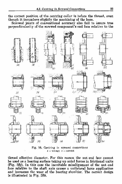
4.2. Centring tn Screwed Connections 93
the correct position of the centring collar is before the thread, even though i t incumbers slightly the machining of the bore.
Screwed joints of conventional accuracy also fail to assure true perpendicularity of the screwed component's end face relative to the
Fig. 58. Centring in screwed connections 1 - wrong; 2 - correct
thread effective diameter. For this reason the nut end face cannot be used as a bearing surface taking up axial forces in frictional units (Fig. 581). In this case the inevitable misalignment of the nut end face relative to the shaft axis causes a unilateral force application and increases the wear of the bearing shoulder. The correct design is illustrated in Fig. 58k.

94 Chapter 4. Screwed Connections
A plunger assembly with a rod sliding in the bore of a screwed-on detachable cover (Fig. 581) does not ensure axial alignment of the holes in the cylinder and cover. An aligning collar tailored beyond the thread boundaries (Fig. 58m) rectifies but partially the displa- cement of the cover.
An aligning collar located nearby the cylinder end face (Fig. 58n) ensures alignment only if the cylinder outside centring surface is made exactly concentric with the hole. Still better is the design with a female thread (Fig. 580); here the collar is centred directly from the cylinder walls. The most reliable way of effecting the align- ment is by means of a cylindrical shoulder with the cover clamped down by a captive nut (Fig. 58p).
Figure 58q-u shows units enabling a continuous adjustment of the axial position of the shaft mounted in a bearing and loaded with a force of constant direction. The alternative in which a thrust plate is screwed on (Fig. 58q) is unsatisfactory due to the plate distortion which causes wear on one side of the plate bearing face. An increase of the threaded portion (Fig. 58r) only worsens the situation. A satis- factory solution is the introduction of a cylindrical centring collar (Fig. 58s) which eliminates the distortion of the plate end face, if it is machined strictly perpendicular to the centring cylindrical surface and the thread clearance is large enough not to interfere with the plate placement on that surface. A still more reliable mount- ing of the plate is illustrated in Fig. 58t where the plate is fitted upon a plain centring collar and i ts axial position is adjusted by means of a nut and a locknut. A still better design is presented in Fig. 58u in which the plate can align itself on the spherical sur- face of the nut.
4.3. Dmign Rules Screw threads in heavily loaded connections must always be tight-
ened, otherwise they will quickly fail, particularly under cyclic and dynamic loads, owing to the crippling, work hardening and, some- times, welding of the threads.
The design of a valve in which the valve plate is screwed into the valve stem (Fig. 59a) is poor, as under the action of forces and bend- ing moments, when the drive cam runs against the plate, the threaded connection works loose. Moreover, the free thread does not accura- tely locate the plate relative to the stem. Lenghtening the thread- ed portion (Fig. 59b) only partially eliminates this disadvantage. I t is better to tighten the screwed connection by a locknut (Fig. 59c). The turnbuckles shown in Fig. 5 9 4 e are similar examples.
Screwed connections of the usual accuracies are not seal-proof. When applying screw threads to vessels containing gases or ,liquids under pressure, preliminary measures must be taken against leakage through the threads. Fitting gasket washers under nuts (Fig. 60a)

4.3. Destgn Rules 95
is insufficient because liquid penetrates along the threads. In such cases one should use cap nuts (Fig. 60b) or install below the nuts bushes having inserts made of some elastic material (rubber, plas- tic), which will assure the sealing of the joint over the plain cylin- drical part on the bolt (Fig. 60c).
Studs the ends of which penetrate into the internal cavity contain- ing the liquid must not be used (Fig. 60d). However, interference-
Fig. 59. Tightening of screwed connections
fitted studs used with sealing compounds assure hermetic sealing but this method is not recommended as there is no guarantee that the replacement studs changed during repairs will continue to seal
(a) (6) Fig. 60. Sealing of screwed connections
correctly. Tightening studs onto sealing gaskets (Fig. 60e) complicat- es the design and is not fully reliable. The best way to prevent leak- age is to fit the studs in blind bosses (Fig. 60f).
Through-holes for studs (ref. No. 1, Fig. 61) and bolts are permitted in spaces where the liquid is present in the form of droplets, splashes or films covering the walls. I n oil baths the fastening studs must be blind-mounted (2).
Plugs in oil-containing cavities must have sealing gaskets (Fig. 62a). Tapered threads (Fig. 62b) have self-sealing properties, particularly when screwed into housings made of plastic metals.

Chapter 4. Screwed Connections
Parts, for which an accurate angular position is essential, should not be screwed in. When positioning a threaded angular pipe con- nection (Fig. 63a), i t s accurate location can be ensured either by scraping the end face surface of the bearing shoulder or by selecting a gasket of a suitable thickness. These measures complicate assembly.
In later reassemblies the correct posi- tion of the connection will inevitably be disturbed. The most advisable so- lution in this case is to mount the connection on a flange (Fig. 63b).
Figure 63c-f shows various bra- cket designs for a handrail. When
Fig. 61. Installation of fasteners in oil-contain-
ing cavities
Fig. 62. Plugs
using a threaded connection i t is practically impossible to put the bracket a t its required angular attitude (Fig. 63c). I t is better to fasten the bracket with a cylindrical stem (Fig. 63d), tightening the nut after the handrail is introduced into the bracket head. The
Fig. 63. Angular location of threaded parts
angular position of the bracket can also be set with a key (Fig. 63e), or by means of a flange (Fig. 63f). Readjustment in the first case is accomplished a t the expense of the clearances between the key and i ts seat, and in the latter case, a t the expense of the clearances be- tween the bolts and their holes in the flange.

4.3. Design Rules 97
Power tightening should always be made possible for threaded connections. I n the poor designs shown in Fig. 64a, c friction forces produced during tightening on the bearing flange ~ u r f ~ c e s , being applied over a large radius, sharply increase the tightening torque, thus making power-tightening impossible. In the correctly designed
Fig. 64. Reduction of tightening torque
versions (Fig. 64b, d) the friction forces act a t the minimum distance from the bolt axis, this distance being equal to the average radius of the bearing surface of the bolt head.
In joints where tightening is effected over gently tapered surfaces (Fig. 64e) power-tightening is impossible because of the impeding
Fig. 65. Tightening over soft gaskets
effect of frictional forces on the tapered surfaces and also due to the compression of the stem threads by those of the nut over the tape- red area. Cone angles not exceeding 90" (Fig. 64f) are recommended.
Tightening on soft materials (packings, gaskets, etc.) should be avoided.
For instance, tightening of a packing gland nut (Fig. 65a) causes twisting and collects the packing on the nut end face. This can be
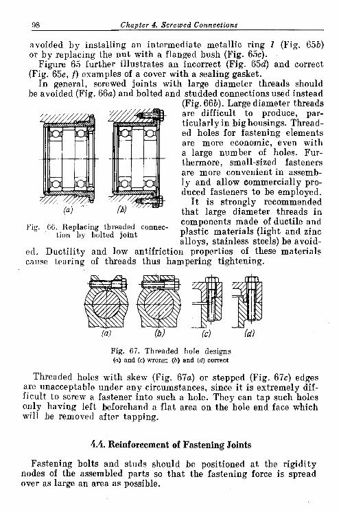
98 Chanter 4. Screwed Connections
avoided by installing an intermediate metallic ring 1 (Fig. 65b) or by replacing the nut with a flanged bush (Fig. 65c).
Figure 65 further illustrates an incorrect (Fig. 65d) and correct (Fig. 65e, f ) examples of a cover with a sealing gasket.
In general, screwed joints with large diameter threads should be avoided (Fig. 66a) and bolted and studded connections used instead
(Fig. 66b). Large diameter threads are difficult to produce, par- ticularly in big housings. Thread- ed holes for fastening elements are more economic, even with a large number of holes. Fur- thermore, small-sized fasteners are more convenient in assemb- ly and allow commercially pro- duced fasteners to be employed.
'//// /////!/m ;b)'/e I t is strongly recommended (a) that large diameter threads in
Fig. 66. Replacing threaded connec- compon&ts made of ductile and
tion by bolted joint plastic materials (light and zinc allovs, stainless steels) be avoid-
ed. Ductility and low antifriction pioperties of these' materials cause tearing of threads thus hampering tightening.
Fig. 67. Threaded hole designs (a) and ( c ) wrong; (b) and (d) correct
Threaded holes with skew (Fig. 67a) or stepped (Fig. 67c) edges are unacceptable under any circumstances, since i t is extremely dif- ficult to screw a fastener into such a hole. They can tap such holes only having left beforehand a flat area on the hole end face which will be removed after tapping.
4.4. Reinforcement of Fastening Joints
Fastening bolts and studs should be positioned a t the rigidity nodes of the assembled parts so that the fastening force is spread over as large an area as possible.

Fig. 68. Positions of fastening bolts
Fig. 69. Methods of reinforcing fastening units
7*

100 Chapter 4. Screwed Connections
The spacing of the lid fastening bolts shown i n Fig. 68a is wrong as the bolts are arranged in bosses positioned in areas weakly con- nected with the part body. Somewhat better is the design i n Fig. 68b where the lid has a stiffening edge improving the force distribution over the tightening area. I n the correctly designed version (Fig. 68c) the bolts are spaced a t the rigidity nodes a t the corners. The rigidity
Fig. 70. Fastening a bearing cap to crankcase
of the lid as a whole is further enhanced by diagonal stiffening ribs, tying up the fastening points with the part body.
Figure 68d shows badly positioned bolts i n an intricately shaped flange. The correctly designed version is pictured in Fig. 68e where the bolts are positioned a t the rigidity nodal points within the part's external contour, which enhances clamping rigidity and improves the outer appearance.
The bosses in cast parts intended for receiving screwed ends of bolts and studs (Fig. 69) must be reinforced with ribs oriented pre- ferably in line with the bolt axis (Fig. 69b-d). Load-carrying studs and bolts (Fig. 69e), particularly when the clamped parts are made from low-tensile alloys, should be screwed deeper into the parts

4.4. Reinforcement of Fastening Joints 101
so that the maximum cross-sectional area of t.he wall is engaged in the work. Furthermore, longer studs under cyclic loads are stronger and ensure a. more reliable fastening.
Figure 70 shows the subsequent stages of strengthening a crank- case and bearing cap assembly loaded in tension. The weakest design is that with the short studs (Fig. 70a). Here is a further defect, namely, the crankcase strengthening ribs are offset relative to the stud axes and do not share the load. In improved versions (Fig. 70b, c) the studs are positioned deep into the case body and the bosses reinforced with ribs. In the design illustrated in Fig. 70d the studs ends are tightened with nuts, relieving the case thread from load; the crankcase cross-section, which works in tension, is reinforced with an arch-shaped strengthening collar.
Studs can be relieved from bending (in one plane) by installing their screwed ends in cylindrical swivelling inserts (Fig. 70e).
The most advisable design (Fig. 70f) has the stud ends outside. The tensioning of the material inherent in the previously illustrated versions is practically eliminated and the load is taken up by the entire crankcase cross-section.

Chapter 5
Flanged Connections
When designing flanged connections i t is necessary to ensure strength and rigidity with the minimum weight, as well as the rigidity of the sections connecting the flanges to the walls of the part.
Illustrated in Fig. 71 are typical flange designs for turned steel cylindrical parts (a sleeve held to a housing), approximately in the order of increasing rigidity.
The design in Fig. 71a is unsatisfactory: the flange connection to the walls is too thin and inadequately rigid. The principal flange strengthening methods are: introducing fillets (Fig. 71b, c) and tapers (Fig. 71d-f) in the areas where the flanges are connected to the walls. When large fillets and tapers are used, nut bearing surfaces are machine faced (Fig. 71c, e, f ) so that the fastening studs may be brought closer to the walls.
The weight of flanges is reduced by holes machined between the fastening studs (Fig. 72a), by removing superfluous material off the periphery (Fig. 72b, c) and surface (Fig. 72d, e), and by face recesses (Fig. 72f, g) and radial recesses (Fig. 72h).
Typical designs of cast flanges are pictured in Fig. 73. The rigidity of flanges is improved by ribbing (Fig. 73b), by making local bosses in the fastening hole areas (Fig. 73c), by making the flanges higher (Fig. 73d-f). To eliminate excessive solidness high flanges are under- cut. Flanges with through undercuts (Fig. 73d) have the disadvantage that the flange is subjected to bending when tightening fastening studs. This shortcoming is eliminated in the design having bosses around the fastening holes (Fig. 73e, f).
Flanges can be reinforced with a continuous peripheral rib (Fig. 73g) linked by transverse ribs to the walls of the part. Occasion- ally a flange is made in the form of two flanges interconnected by bosses of the fastening holes (Fig. 73h).
Rigidity is significantly enhanced by locating fastening studs in recesses, which have semi-circular cross-sections (Fig. 73i-k). Still further improvement can be attained by increasing the height of fastening stud bosses (Fig. 731, m).
In the designs depicted in Fig. 73n-p the stud-receiving bosses are made in the form of columns; the nut-bearing surfaces are slightly

Fig. 71. Flanges on lathe-turned cylindrical parts
ia I b (C) (dl re) c f ) ( 7 (;I
Fig. 72. Methods of reducing the weight of flanges
Fig. 73. Flanges on cast parts

104 Chanter 5. Flaneed Connections
raised above the top horizontal wall of the part. This enables column end faces to be through-machined and facilitates nuts tightening. The highest strength and rigidity are possessed by the design pictured in Fig. 73p in which the vertical wall of the part is matched with the column extreme points.
Figure 74 shows flange designs of conical and spherical castings. With small (in respect to flange diameter) cone sizes the flange is connected to the part walls by means of a tulip-shaped mouth
Fig. 74. Flanges on conical and spherical parts
(Fig. 74a), thus ensuring a streamlined transition of the force flow from the part walls to the flange. In cones of large diameter sizes the joint between the flange and the part walls is reinforced with ribs (Fig. 74b-d) or by positioning fastening holes in recesses (Fig. 74e, f).
With small slope angles the recess walls are extended excessively. In these cases they are given a semi-closed arched form (Fig. 74g).
To obtain the greatest rigidity and strength the walls are position- ed a t the flange periphery and the recesses ceiling linked with the walls by internal ribs (Fig. 74h).
The sizes of the vaulted recesses in height and cross-section must permit easy assembly of fastening parts. With insufficient height (i.e., when the
Fig. 75. Mounting fasteners in recesses
clearance h between the recess ceiling and stud end face is less than nut height h,, Fig. 75a) , the unit can be assembled only by raising the part (Fig. 75b) and placing all the nuts on the studs ends, a procedure seriously hampering the assembly. The correct version (h > ho) is pictured in Fig. 75c. When using bolts (Fig. 75d) the recess height must be greater than the bolt length.

5.1. Alienment o f Flanges 105
To reduce the weight of low flat flanges the latter are often shaped (in plan), making them narrower in width a t the areas betweenfasten- ing bosses (Fig. 76a-c, g-i). In the extreme limit the flange actually vanishes so that only bosses remain which are cast directly onto the part walls (Fig. 76d, j ) . These methods must be used very carefully
Fig. 76. Reducing the weight of cast flanges
since the flange rigidity and strength is lowered and the connection between the bosses and part walls weakened. When reducing the flange width to trespass beyond the fastening holes centre line i s not recommended (Fig. 76b, h). I t is useful to strengthen the connection between bosses and part walls with local ribs. More preferable are solid flanges (Fig. 76f, 1) ensuring higher rigidity and better fasten- ing stability.
5.1. Alignment of Flanges
Cylindrical flanges are usually aligned by a shoulder and a recess which are machined on the flanges and fit to one another (Fig. 77a, b). In the joints fastened with screwed-in bolts or studs the above-said
Fig. 77. Centring of cylindrical flanges
recess is substituted by the minimum internal flange diameter of one of the flanges (Fig. 77c). Alignment can also be accomplished on an external flange rim (Fig. 77d).
The aligning shoulder must be a t least 3-4 mm distant from the extreme points of fastening holes (Fig. 78a), otherwise thin rags (m) or sharp-pointed burrs (n) will form which easily break in service and impair the shape of sealing gaskets.

106 Chanter 5. Flanged Connections
In exceptional cases, in order to obtain smaller sizes, the aligning step can be provided a t the area where fastening holes are located (Fig. 78b-d). This method is practicable only for bolted connections; cutting threads in stepped holes and screwing-in fastening elements into such holes offer formidable diffi- culties. Stepped holes are machined on assembly which complicates manufactur- ing. The designer should not position the centre-aligning step behind the axial
I A A-A
Fig. 78. Centring of flanges
Line of fastening holes (Fig. 78b, c) as this would inevitably lead to the formation of sharp rags and burrs. Furthermore, such connections bend as the fastening bolts are being tightened. As obvious from Fig. 78c a gap formed in the joint accumulates dirt. An acceptable interval a t which the centre-aligning step may be positioned is 0.25 hole diameter from the holes axial line (Fig. 78d).
To attain close contact between the joint surfaces i t is necessary to preclude the corners of aligning surfaces from touching each other. This can be achieved by providing a chamfer that clears the fillet radius where the aligning shoulder meets the flange (Fig. 79a) , or i t can also be accomplished by radial, face or diagonal undercuts (Fig. 79b-d).
The height H (see Fig. 79a) of centre-aligning steps can be taken for conventional joints a t 0.5 1/0 (D - centring diameter).
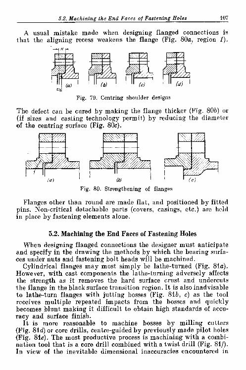
5.2. Machining the End Faces of Fastening Holes 107
A usual mistake made when designing flanged connections is that the aligning recess weakens the flange (Fig. 80a, region 1 ) .
. .
Fig. 79. Centring shoulder designs
The defect can be cured by making the flange thicker (Fig. 80b) or (if sizes and casting technology permit) by reducing the diameter of the centring surface (Fig. 80c).
Fig. 80. Strengthening of flanges
Flanges other than round are made flat, and positioned by fitted pins. Non-critical detachable parts (covers, casings, etc.) are held in place by fastening elements alone.
5.2. Machining the End Faces of Fastening Holes
When designing flanged connections the designer must anticipate and specify in the drawing the methods by which the bearing surfa- ces under nuts and fastening bolt heads will be machined.
Cylindrical flanges may most simply be lathe-turned (Fig. 81a). However, with cast components the lathe-turning adversely affects the strength as i t removes the hard surface crust and undercuts the flange in the black surface transition region. I t is also inadvisable to lathe-turn flanges with jutting bosses (Fig. 81b, c) as the tool receives multiple repeated impacts from the bosses and quickly becomes blunt making i t difficult to obtain high standards of accu- racy and surface finish.
I t is more reasonable to machine bosses by milling cutters (Fig. 81d) or core drills, centre-guided by previously made pilot holes (Fig. 81e). The most productive process is machining with a combi- nation tool that is a core drill combined with a twist drill (Fig. 81f). In view of the inevitable dimensional inaccuracies encountered in

108 Chapter 5. Flanged Connections
moulding practice, the core drill diameter D is made larger than the nominal boss diameter Do (on average D = 1.2D0). This must be allowed for when specifying joint dimensions.
When spot facing sunk bearing surfaces (Fig. 81g) the flange con- tour should be 3-4 mm distant from the extreme points of the machin-
Fig. 81. Machining methods for nut and bolt head bearing surfaces
ed surfaces. Otherwise the possibility of forming the easily broken rags and burrs occurs.
If a core drill cannot be used directly on the work surface then inversed core drilling is practised, where the core drill is mounted upon an arbor passed through a previously drilled hole (Fig. 81h). Machining efficiency is sharply reduced with this method, so that the latter is applicable in the event of holes not less than 10-12 mm in diameter.
The end faces of holes in half-closed recesses are machined by milling (Fig. 82a) or inversed core drilling (Fig. 82b). The height and radius R of recesses, taken in cross-section, must be consistent with the dimensions of cutting tools.
The modern highly accurate casting techniques (shell mould casting, chill casting, pressure die casting, investment casting, etc.) obviate, in certain cases, machining of support surfaces. However, for critical, heavy-loaded structures

5.2. Machining the End Faces of Fastening Holes 109
machining is obligatory with the assurance that the bearing surfaces are strictly perpendicular to the hole axis, thus avoiding fastening bolt distortion and flexure.
Table 6 gives the moulded flange design relationships for the conventional range of bolt diameters (d = 8-20 mm).
The machining allowance t depends on the size and grade of accu- racy of the casting. On drawings which depict cast components
Fig. 82. Machining bearing surfaces in recesses
the value of t is generally omitted, which, nevertheless, in no way implies that the designer may neglect this value when calculating the dimensions of parts.
The minimum distance s between the machined and the nearest black surfaces is established proceeding from the accuracy standards of casting, dimensions of parts and distances of surfaces from the

110 Chanter 5. Flanged Connections
Table 6 Relationships of Cast Flange Elements
black and machined datum points. With respect to the small- and medium-sized components (200-500 mm) obtained by conventional sand casting s = 3-5 mm; these values can be reduced by 30-50% by applying higher-accuracy casting methods.
Flange elements
Mini- mum flangv height h
Mini- mum di-
mensions of machined surfaces (a. R, 0 1 2 )
Mini- mum bolt axis distan- ce b from machined wall
Minimum bolt axis distance A from flange end face
5.3. Diameter and Spacing of Bolts
The proper choice of the diameter and spacing of bolts depends on many factors, the most important of which are the operational conditions, material of parts and rigidity of structures. The require- ments are quite different for connections subjected to small static loads and connections undergoing high cyclic and dynamic loads, working under pressure and where complete sealing is necessary.
For the simplest cases (flange-coupled connections, loaded with moderate forces, free of internal pressure and elevated tempera- tures), the following approximations can be recommended.
%Fy ,:'f,"y"S bronze
1.5d
1.2d
1.3d
1.7d
Mater~al
steel, high-
tensile
1.2d
1.2d
1.2d
1 .56

5.4. Three-Flange Joints 111
The diameter of bolts fastening cylindrical flanges
where D is the mean flange diameter. The thickness of the flanges: for components made of grey cast iron and light alloys
I , ! 1
.- 1 -
Fig. 83. Bolt spacing for flanges of different rigidity
for components made of steel or high-strength cast iron
h = 4 + (0.022 to 0.025) D, The pitch of bolts
I = ad
For small-sized non-rigid flanges (Fig. 83a) a = 6-8; for mode- rately rigid flanges :(Fig. 83b) a = 8-10; for flanges of higher rigidity fastened with large bolts (Fig. 83c) a = 10-12.
The parameters of joints subjected to cyclic loads and operating at elevated temperatures are obtained by calculation (see Chapter 1).
5.4. Three-Flange Joints
When designing housing-type components i t is often necessary to connect three flanges in one unit. Let us take, as an example, a unit comprising an intermediate partition (membrane) installed between the joint faces of two housings (Fig. 84).
The simplest method is tightening the membrane between the flanges of the housings (Fig. 84a-e), the alignment being accomplished from internal or external shoulders. The installation accuracy is the highest in Fig. 84b, c and e (the alignment is effected from one cylindrical surface).
The design presented in Fig. 84e is less strong than the others. To
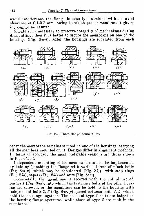
112 Chapter 5. Flanged Connections
avoid interference the flange is usually assembled with an axial clearance of 0.1-0.2 mm, owing to which proper membrane tighten- ing cannot be assured.
Should i t be necessary to preserve integrity of mechanisms during dismantling, then i t is better to secure the membrane on one of the housings (Fig. 84f-i). After the housings are separated from each
Fig. 84. Three-flange connections
other the membrane remains secured on one of the housings, carrying a l l the members mounted on i t . Designs differ in alignment methods. In terms of accuracy the most preferable versions are those shown i n Fig. 84h, i.
Independent mounting of the membrane can also be implemented by holding (pinching) the flange with various forms of pinch bolts (Fig. 84j-p). which may be shouldered (Fig. 84j), with stop rings (Fig. 84k), tapers (Fig. 841) and nuts (Fig. 84m).
Occasionally the membrane is secured with the aid of tapped bushes 1 (Fig. 84n), into which the fastening bolts of the other hous- ing are screwed, or the membrane can be held to the housing with independent bolts 2, 3 (Fig. 840, p) spaced between bolts 4, 5 , which hold the housings together. The heads of type 2 bolts are lodged in the housing flange apertures, while those of type 3 are sunk in the membrane.
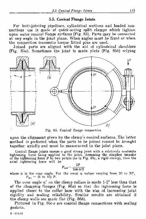
5.5. Conical Flange Joints 113
5.5. Conical Flange Joints
For butt-j,ointing pipelines, cylindrical sections and loaded con- nections use is made of quick-acting split clamps which tighten upon outer conical flange surfaces (Fig. 85). Parts may be connected a t any angle in the joint plane. When angles must be fixed or when the connection transmits torque fitted pins are used.
Joined parts are aligned with the aid of cylindrical shoulders (Fig. 85a). Sometimes the joint is made plain (Fig. 85b) relying
Fig. 85. Conical flange connection
upon the alignment given by the clamp's conical surfaces. The latter method is preferred when the parts to be joined cannot be brought together axially and must be manoeuvred in the joint plane.
Conical flange joints ensure a good strong joint with a relatively moderate tightening force being applied to the joint. Assuming the simplest transfer of the tightening force P to two points (as in Fig. 85c, a rigid clamp), then the axial tightening force will be
2P Pa,= -
tan a/2 where a is the cone angle. For the usual a values varying from 20 to 30°,
Pa, = (8 to 10) P.
The cone angle a' on the clamp collars i s made 1-2" less than tha t of the clamping flanges (Fig. 86a) so that the tightening force is applied closer to the collar base with the aim of increasing joint rigidity and sealing reliability. Similar results are obtained if the clamp walls are made flat (Fig. 86b).
Pictured in Fig. 86c-e are conical flange connections with sealing gaskets.

114 Chanter 5. Flanged Connections
Figure 86f-h illustrates various designs of thin-walled tube conic- al flange connections.
In certain cases inverted conical flange connections are employed. The invert- ed conical flanges of the connected arts have through slots (Fig. 87a). During P assembly the projecting lug of one f ange enters the slot in the other, thereby forming between the flanges a conical cavity into which is placed the central tightening collar (Fig. 87bl.
The binding clamp of a taper flange joint must open fully so that it may be installed on the flanges from the side and axially and
Fig. 86. Conical flange connections
assure uniform circumferential flange tightening, i.e., be compliant radially. The clamp must be quick-acting.
The clamp comprising two halves fastened together by bolts (Fig. 88a) is not quick-acting. A more practicable design has i ts
Fig. 87. Inverted conical flange connection
halves linked with a pin and tightened by one bolt (Fig. 88b, c). In the quick-action lock with a swing bolt (Fig. 88d) radial slits
are provided in the hoop walls to enhance the compliance of the system. A circlip-type lock is applied to fasten light joints (Fig. 88e).
I n a load-carrying structure furnished with a quick-action lock (Fig. 88f) the coupling bolt extends through a cylindrical nut I

5.5. Conical Flange Joints 115
mounted in a half-open cup; the bolt end terminates in articulated joint 2. As the bolt is being unscrewed, the nut leaves the cup and the bolt can be freely swung away by rotating i t about the joint axis.
In the design pictured in Fig. 88g the two halves are tightened together by means of a swing lever with pressure screw 3. In the
Fig. 88. Collar clamps
version presented in Fig. 88h use is made of a swing-type three-link mechanism ("frog"). I n the latter case an elastic packing must be inserted between the flanges, which would compensate for the rigi- dity inherent in such a mechanism in the locked position.
Figure 88i illustrates an elastic clamp made of a steel ribbon with welded-on channel-sectioned segments 6. The coupling bolt extends through pin 4 of the articulated joint and is screwed into the cylin- drical nut 5.

Chapter 6
General Principles which Should Be Followed
when Designing Units and Parts
6.1. Unification of Design Elements
When designing one should repeatedly use elements for all parts of the design which in the assembly process reveal average rated parameters and allow the parts' list to be reduced to its mini- mum.
Subject to unification in the first instance are fitted connections (their nominal sizes, type of fits and classes of accuracy), threads (diameter, pitch and classes of accuracy), splined and keyed con- nections, fasteners, specifications, etc. I t is also advisable to reduce the number of material grades, unify surface finish classes, finishing operations and electroplating techniques, welding methods, forms of welded seams, etc.
Figure 89a-c illustrates the arrangement of a typical engineering unit (a shaft carrying some elements and mounted in a bronze bush). I n the design presented in Fig. 89a the choice of fitting diameters i s badly thought over. The basic fitting size (diameter of the shaft bearing journal), taken from standard specifications (+ 50), is cor- rectly chosen, but from this point mistakes occur. Wishing to eco- nomize on the consumption of scarce bronze, the designer used a bush wall thickness of 3.5 mm, thus obtaining a non-standard size for the external diameter of the bush (+ 57) and, moreover, while striving to enhance the shaft strength a t the fitted connection, he reduced the shaft diameter relative to the journal diameter by 3.5 mm on each side, thus obtaining again a non-standard diameter (+ 43), which, in turn, meant choosing an M42 screw thread size for the clamping nut.
In the arrangement inFig. 89b, which is based on standard dimen- sions, the external diameter of the bush is 60 mm and the diameter of the fitted connections 40 mm. Hence, the clamping nut thread size is M37. However, standardization of the dimensions in this case has lowered somewhat the shaft strength and also increased the weight of the bronze bush. The most rational version depicted in Fig. 89c has its shaft journal diameter equal to 55 mm, bush O.D. 60 mm and the fitted connection diameter 45 mm.

Fig. 89. Unification of design elements

Table 7 Comparative Table of the Back Gearing Dimensions
Design element
Diameters and fits
Design para- meter according
to Fig. 89d
30P
35AIR
40AIS
40AIP
42AIS
45AIS
45AIDh
50AIR
55AIDh
Qnty
1
1
1
1
1
1
( 1 1
1
Design para- meter according
to Fig. 89e
35P
40AIR
45AIS
50AIDh
I
Qnty
2
2
Design element
Threads
Design para- meter according
to Fig. 89d
M 25
M37
Qnty
1
1
I 1
3
1
Keys b, mm
Tooth mo- dule, rn
Design para- meter according
to Fig. 89e
M30
6
8
10
4
5
6
Total
Qnty
2
8 1
1
7
1
1
1
18
5

6.2. Unification of Parts 119
Naturally, other solutions are possible, but under any circumstan- ces i t is important for the diameters to be standard. Another example is given i n Fig. 89d, e (back gear).
The design in Fig. 89d has significant irregularities in the sizes of fitting diameters, threads, keys and tooth mod- ules. I n the rational version shown in Fig. 89e the number of fitting dimensions has been reduced and the keys and to- oth modules unified. The ne- cessary tooth strength for the small gears is obtained by the increased face width. The uni- fication results are presented Fig. 90. Unification of wrench sizes in Table 7. All-in-all the num- ber of machine elements is cut down from 18 to 7 items.
To illustrate the unification of wrench sizes, let us consider a unit for adjusting a reduction valve (Fig. 90). In the design shown in Fig. 90a three wrench sizes (1-3) are used, whereas the unified design in Fig. 90b uses only a single wrench size (4).
6.2. Unification of Parts
Individually designed parts must be unified as much as possible. This is particularly important for labour-consuming parts and those in general use (gears, clutches, chain links, etc.).
Figure 91a shows a conveyer chain composed of links of two types. The rational design (Fig. 91b) has unified links. The tightening clamp illustrated in Fig. 91c consists of two labour-consuming com- ponents. Connection by an intermediate link (Fig. 91d) enables the clamp to be made of two similar halves. Figure 91e, f shows the uni- fication of pressed steel components in the unit of a built-up pulley, while Fig. 91g, h shows unification embodied in the design of a cylindrical pressed reservoir.
Often unification is only attained as a result of purposeful, ori- ginal, constructional working out of the design.
In an angle drive present,ed in Fig. 92a the required gear ratio is ensured with the aid of two different shafts having different bevel gears. To position the lower gears within preset spaces, one of the gears is displaced relative to the other and the tooth face width of the driving gear 1 made longer. As a result, the design contains five gears (numbered 1 to 5) and two shafts (numbered 6 and 7).

Fig. 91. Unification of parts
Fig. 92. Unification of parts in angle drive unit
t Q 1 t b l
Fig. 93. Unification of parts in coaxial reduction gear unit

6.3. Princinle o f Unitization 121'
In the alternative, Fig. 92b, the diameter of lower gears 2 is de- creased so that they can be driven by the one gear I. Tp keep the gear ratio the same the diameter of upper gears 3 is increased. As a result of the conversion the required number of gears is reduced to three ( I to 3) and of the shafts, to one (4).
Now, let us examine a reduction gear unit with two concentric shafts running a t the same speed in opposite directions (Fig. 93a). The unit driving shaft carries two gears, one of which (I) engages with gear 2 of the reduction unit, while the other (3) meshes via idler 4 with gear 5. The total number of gear units is four (1-3, 2, 4, 5). The large number of components and complexity of the design are caused by the necessity to avoid fouling between gears 3 and 5 , which means reducing the diameter of gear 3 and, accordingly, that of gear 5 (in order to retain the same gear ratio).
In the unique solution (Fig. 93b) the design is simplified as fol- lows: gear 1 of the drive shaft meshes on one side with the reduction unit right-hand pinion and on the other side, with gear 2 of the drive. The number of gears is thus cut down to two and the pinions and gear wheels of the unit are identical pairs. To realize this design i t is sufficient to separate the gear wheels by a distance s sufficient to engage the pinions.
6.3. Principle of Unitization
I t is advisable to design units as self-contained assemblies, which are individually assembled, adjusted, run-in, tested and finally installed as completely ready-to-operate units upon a machine. Such successive unitization allows parallel and independent assembly of machine units, facilitates mounting, prompts prototype testing and eases the employment on new machines of finished units which were checked during manufacture. Furthermore, unitization simpli- fies repair as worn out units can be directly replaced by new ones. Sometimes unitization may complicate the design, but in the long run, i t always gives large savings in the total machine manufactur- ing costs, reliability and convenience in use.
Some examples of the unitization of small assemblies are presented in Fig. 94. In the design illustrated in Fig. 94a the reduction valve is mounted directly in the housing body. When the valve is assembled in a separate bush the design becomes unitized (Fig. 94b).
The end face seal depicted in Fig. 94c is unsatisfactory because during dismantling the sealing disk 1 is forced by the spring to leave the ways and slots which prevent its rotation, and the unit disintegrates. Equally unsuitable is the seal assembly. The intro- duction of locking ring 2 unitizes the construction (Fig. 94d).
Another example of unitization is offered in Fig. 94e-g where the unit of a distributing slide valve is shown progressively improved-

,122 Chapter 6. General Design Principles
The construction given in Fig. 94e is grossly wrong: an accurate hole intended to receive the valve was made directly in the frame casting. At the spot where the valve is located (i.e., in the concentra- tion of material) there may occur pits and voids which make valve sealing impossible. Moreover, as the hole wears out during use i t can only be repaired by introducing bushes.
The first step to an improved design is to mount the valve in an intermediate bush (Fig. 94f) made of a high-grade material with a
Fig. 94. Examples of unitization
.good wear resistance. In the most rationally designed version (Fig. 94g) the component has been fully unitized. Here the unit is made separately; i t is assembled, ground-in, verified for geometry and attached to the frame on a milled surface.
Shown in Fig. 95a is a worm reducer which is coupled directly with the machine driving shaft. The worm wheel shaft is mounted in supports installed in different housings. To maintain support alignment when machining is difficult. The assembly procedure is

6.3. Principle of Unitization 123
very ambiguous as i t is necessary to f i t the worm wheel first onto the main shaft, install the reducer housing and then assemble the worm by screwing it into the worm wheel teeth. To verify the cor-
fa! (b)
Fig. 95. Unitization of gear transmissions
rectness of engagement and align the worm wheel under these cir- cumstances is very difficult.
In the unitized construction (Fig. 95b) the worm wheel shaft is mounted in two supports, one of which is accommodated inside the housing and the other in the housing cover. Both supports can be machined together, thus obtaining good alignment. The shaft end

124 Chapter 6. General Design Principles
is coupled with the driving shaft by the splined adapter 1 . Hence, the reducer assembly is considerably simplified.
The gearing mounted in a frame (Fig. 95c), in addition to the draw- backs inherent in the non-unitized constructions, presents diffi- culty in introducing the idle gear shaft into the support housing. As soon as the housing is removed from frame, i t loses both supports and falls to pieces. To verify the correctness of meshing and align- ment of the shaft and supports is impossible.
In unitized constructions the gear supports are mounted in diaph- ragm 2 (Fig. 954 , or in bracket 3 (Fig. 95e) screwed by i ts feet to the gearing casing. With the latter design i t is easy to inspect the mechanism during assembly.
Figure 95f, g shows the unitization of a gear drive mounted on a frame; Fig. 95h, i, a reduction unit driven from anengine crankshaft. In the unitized version (Fig. 95i) the reduction unit is mounted in a separate housing; the shaft torque is transmitted by means of a d a p ter 4.
6.4. Elimination of Adjustments
Fitting and adjustment of units and parts when in position must be eliminated. Adjustments, particularly when accompanied by machining or fitting operations, lower assembly productivity and deprives the construction of interchangeability.
An example of fitting in situ is shown in Fig. 96a, b. The gear i s placed in position on the shaft so that it meshes with i t s mating gear. This done, the position is fixed by a self-piercing screw (Fig. 96a) or by a taper pin (Fig. 96b), which requires drilling and reaming in situ. Chips inevitably fall into the unit. After the machining i t is necessary to dismantle the unit, flush i t and then reassemble. Marking during assembly with a subsequent transfer to machine tools further complicates assembly.
A better engineering method is to lock the gears in position by ring-shaped stop washers which are placed into grooves previously machined on the shaft (Fig. 96c).
If a bearing has been installed in a housing by the "in situ" tech- nique (Fig. 96d), i ts originally correct position will be disturbed every time the bearing is dismantled, thus necessitating readjust- ment. Fixing the bearing by dowel pins (Fig. 96e) entails machining on assembly. The correct solution is displayed in Fig. 96f, where the bearing is aligned against the bore in the housing, this bore being machined to the required accuracy, which ensures correct functioning of the unit.
If a straight machine way is mounted on a bed as illustrated in Fig. 96g, then i ts position must be verified on assembly and holes drilled to suit fastening bolts. In this case the way will not be gua- ranteed against offset within the clearance values existing between

lei I f )
Fig. 96. Elimination of adjustments
Fig. 97. Elimination of adjustments when assembling units
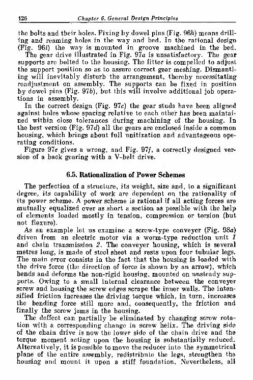
126 Chapter 6. General Design Principles
the bolts and their holes. Fixing by dowel pins (Fig. 96h) means drill- ing and reaming holes in the way and bed. In the rational design (Fig. 96i) the way is mounted in groove machined in the bed.
The gear drive illustrated in Fig. 97a is unsatisfactory. The gear supports are bolted to the housing. The fitter is compelled to adjust the support position so as to assure correct gear meshing. Dismantl- ing will inevitably disturb the arrangement, thereby necessitating readjustment on assembly. The supports can be fixed in position by dowel pins (Fig. 97b), but this will involve additional job opera- tions in assembly.
In the correct design (Fig. 97c) the gear studs have been aligned against holes whose spacing relative to each othei- has been maintai- ned within close tolerances during machining of the housing. In the best version (Fig. 9 7 4 all the gears are enclosed inside a common housing, which brings about full unitization and advantageous ope- rating conditions.
Figure 97e gives a wrong, and Fig. 97f, a correctly designed ver- sion of a back gearing with a V-belt drive.
6.5. Rationalization of Power Schemes
The perfection of a structure, i t s weight, size and, to a significant degree, i ts capability of work are dependent on the rationality of i ts power scheme. A power scheme is rational if all acting forces are mutually equalized over as short a section as possible with the help of elements loaded mostly in tension, compression or torsion (but not flexure).
As an example let us examine a screw-type conveyer (Fig. 98a) driven from an electric motor via a worm-type reduction unit I and chain transmission 2. The conveyer housing, which is several metres long, is made of steel sheet and rests upon four tubular legs. The main error consists in the fact that the housing is loaded with the drive force (the direction of force is shown by an arrow), which bends and deforms the non-rigid housing, mounted on unsteady sup- ports. Owing to a small internal clearance between the conveyer screw and housing the screw edges scrape the inner walls. The inten- sified friction increases the driving torque which, in turn, increases the bending force still more and, consequently, the friction and finally the screw jams in the housing.
The deffect can partially be eliminated by changing screw rota- tion with a corresponding change in screw helix. The driving side of the chain drive is now the lower side of the chain drive and the torque moment acting upon the housing is substantially reduced. Alternatively, it is possible to move the reducer into the symmetrical plane of the entire assembly, redistribute the legs, strengthen the housing and mount i t upon a stiff foundation. Nevertheless, all

6.5. Ratlonalizatlon o f Power Schemes 12T
these measures fail to eliminate the principal defect, namely, the presence of external forces in the system.
A radical solution is presented in Fig. 98b. Here the screw is driven from a flange-mounted electric motor via a reduction unit installed coaxially on the housing end face. The drive torque and reactance
torque on the housing quench each other a t the connection joint, The housing is absolutely free from the action of external forces and deformation is eliminated.
I n the drive of a suspended conveyer (Fig. 99a) comprising a reduc- tion unit 1 , bevel gearing 2 and spur gears 3, which impart motion to the driving sprocket 4 of a chain drive, the load-carrying elements are irrationally arranged. Indeed, the support units of the drive, the fastening bolts and foundations are all loaded with drive forces and a large number of elements are in flexure. The drive units are.

128 C h a ~ t e r 6. General Desian Princinles
separated; they are installed on individual bases and are not fixed one relative to the other. Such a design only ensures satisfactory functioning after the mechanisms have been carefully aligned.
Furthermore, the cast iron gears are not protected from fouling and can only be periodically lubricated by packed grease. The
Fig. 99. Improvement of power scheme of suspension-type conveyer drive
supports of the horizontal and vertical shafts are also lubricated periodically.
The entire unit is excessively large, explained by the isolation of units and also by the employment of a low-strength material (cast iron) for manufacture of the most critical components (gears).
In fact, the design is typical of old design practice. In the modern unitized enclosed construction with a rational power
arrangement (Fig. 99b) the drive is from a flange-mounted electric motor, installed vertically, which obviates the necessity for the angular transmission. The required gear ratio is obtained in one co- axially mounted reduction unit. The employment of gears made of a high-grade and appropriately heat-treated steel in conjunction with the application of a centralized oiling system, sharply reduces overall sizes. The drive forces are absorbed in one casing. The casing and base are loaded only by the force of the final driving sprocket. These changes result in tremendous savings in the weight and size of the installation, simplicity of manufacture, convenience in mounting and attendance, reliability and a long service life.
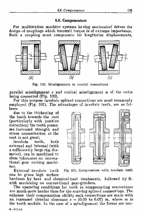
6.6. Compensators 129
6.6. Compensators
For multistation machine systems having mechanical- drives the design of couplings which transmit torque is of extreme importance. Such a coupling must compensate for lengthwise displacements,
(4 h! (c)
Fig. 100. Misalignments in coaxial connections
parallel misalignment e and conical misalignment a of the units being connected (Fig. 100).
For this purpose involute splined connections are most commonly employed (Fig. 101). The advantages of involute teeth, are as fol- lows:
due to the thickening of the tooth towards the root (particularly with positive correction) the tooth posses- ses increased strength and stress concentration a t the root is not great;
involute teeth, both external and internal (with a sufficiently large rim dia- meter), can be machined to close tolerances on conven- tional gear cutting machi- nes.
External involute teeth Fig. 101. Compsnsators with involute teeth can be given high surface hardness by heat and chemical-heat treatments, followed by fi- nish machining on conventional gear-grinders.
The operating conditions for teeth in compensating connections are much more harder than for the centring splined connections. The enhance their compensation ability such connections are made with an increased circular clearance s = (0.05 to 0.07) m, where m is the tooth module. In the case of a misalignment the forces are con- 9-01418

130 Chanter 6 . General Design Principles
centrated a t the tooth extreme edges lying in a plane perpendicular to the misalignment. As a result the linear contact over the tooth face changes to point contact, thus sharply increasing local bear- ing stresses. Since each tooth passes through the zone of loading twice per revolution, the load upon the teeth will be cyclic, regardless of torque behaviour.
The working capacity of the connection can materially be inten- sified by enhancing surface hardness of teeth. To eliminate work bar- dening and promote removal of heat, produced during tooth impacts and warpage, ample lubrication is obligatory. The most effective
Fig. Determination of maximum con ica (b)
1 misalignment in a compensa
method of obtaining an efficient connection is to increase the gear rim diameter since this offers certain advantages in manufacture, namely, the internal teeth can be gear-cut in place of using expensive broaches.
The amount of misalignment admissible in a coupling is limited, first of all, by the tooth edge contact in a plane perpendicular t o the misalignment direction (Fig. 102a). The teeth positioned in the misalignment plane have much displacement: freedom as the clear- ance in the radial direction with a standard pressure angle (20") is approximately three times greater t,han the circular clearance.
The maximum possible misalignment angle a may be determined from the relation
where s = circular clearance in teeth I = tooth face width
The maximum displacement of the compensator's extreme points
where L is the compensator length.
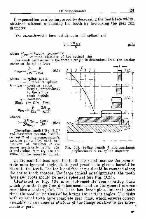
6.6. Compensators 131
Compensation can be improved by decreasing the tooth face width, obtained without weakening the tooth by increasing the gear rim diameter. .
The circumferential force acting upon the splined rim
where Mtqe = torque transmitted D = mean diameter of the splined rim
For small displacements the tooth strength is determined from the bearing stress on the spline faces
P P Gbear = -= -
lzh lzam (6.3) 7 6 5 4 3 2 1
where 1 = spline width z = number of splines
h = am = working spline height, proportional to the spline tooth module
a = constant Since z = ~ / m , then
P 2Mtqe Gbear=-=-
Dla Dzla
whence const 2Mtqe - 1 = -
D2abear 1)2 (6.4)
The spline length I [Eq. (6.4)l and maximum possible displa- cement S of the compensator's extreme points [Eq. (6.1)] as a function of diameter D are
I 1 shown graphically in Fig. 103 Fig. 103. Spline length 2 and maximum (s and I when D = Do are as- displacement S us. spline diameter sumed to be equal to unity).
To decrease the load upon the tooth edges and increase the permis- sible misalignment angle, it is good practice to give a barrel-like shape to the teeth. The tooth end face edges should be rounded along the entire tooth contour. For large conical misalignments the tooth faces and roots should be made spherical (see Fig. 102b).
Illustrated in Fig. 104 is an intermediate compensating bush which permits large free displacements and in i ts general scheme resembles a cardan joint. The bush has incomplete internal tooth rims; the toothed portions of both rims are a t right angles. The disks with external teeth have complete gear rims, which ensures correct assembly a t any angular attitude of the flange relative to the inter- mediate part.
9*

id Chanter 6. General Destnn Prtncinles
Some of the design alternatives of compensating connections are presented in Fig. 105. Connection by means of splines cut directly on drive shafts (Fig. 105a) is unreasonable, because the compensa-
tion ability of such a joint is rather low and i t is determi- ned only by the amount of spline displacement in the gap between spline edges. In- creasing the drive shaft shank length (Fig. 105b) only worsens the position since the splined shank owing to inevitable manufacturing inaccuracies and assembly is apt to runout proportional to the distance a t which the end is spaced
Fig. 104. Cardan-type compensator from the drive shaft supports. If a s ~ l i n e d reducing.
bush is freefy mounted upoG the splines of shafts and acts as an .adapter (Fig. 105c), then the compensating ability, determined by the total clearance in the splines will be twice that of the design given in Fig. 105a.
Fig. 105. Transmission of torque through a compensator
The best construction has the driving ends of the splined bush spaced apart longitudinally (Fig. 105d). Compensation in this instan- ce is improved due to the displacement of the bush itself. Still better i s the case when a longer bush is used (Fig. 105e). However, this alternative is more difficult to produce because of the different splined rims on the bush ends.
The best design has a long splined shaft, a torsion bar (Fig. 105f), having high compensation characteristics.

6.7. Torsion Bars 133 -
6.7. Torsion Bars Torsion bars (torsion bar springs) not only compensate for mis-
alignments, they also damp torque-induced vibrations, thus contri- buting to quieter and smoother operation. This advantage is par- ticularly important in machines operating under pulsating torsional loads (piston-operated machines).
Thanks to their small radial dimensions, torsion bars can readily
Fig. 106. Torque transmission by means of torsion bars
be included in shaft interiors, thereby adding to the compactness of design (Fig. 106a).
To avoid the breakage of torsion bars by overloading, provision is occasionally made of a torque limiter. The latter is generally made in the form of a splined bush mounted concentrically with the tor- sion bar (Fig. 106b). The side clearance in the torque limiter splines exceeds that of the torsion bar splines so that the limiter takes up the load as soon as a certain angle of torsion is reached.
General-purpose torsion bars are made of silicon spring steels, grades 60C2A, 70C3A or 60C2XA, which, when subjected to appropriate heat treatment (harden- ing plus moderate tem ering), possess a fatigue limit zo = 65-70 kgf/mma under pulsating torsionaf loads and 4 = 30-35 kgflmm' under symmetrical alternating torsional loads.

134 Chapter 6. General Design Principles
For stressed structures, as well as for structures operating under elevated temperatures, use is made of silicon-nickel, silicon-tungsten and silicon-vana- dium steel grades 60C2H2A, 65C2BA and 60C2X@A, for which T, = 80- 90 kgflmm? and T - ~ = 40-50 kgfImm2.
The elastic torsion of torsion bars can be enhanced by increasin the design stress Level. For pulsating cycles r = 30-10 kgf/mm2 is generafly adopted, which corresponds (in terms of fatigue limits) to a safety margin of the order of 1.5-2. In structures designed for a limited service life the admissible stresses can be increased to 80-100 kgf/mm2.
The fatigue strength of torsion bars can materially be improved by means of plastic strain hardening. For instance, torsion bars intended for operation under alternate cyclic loading, are hardened by shot blasting, while torsion bars, designed for pulsating loads are hardened through prestraining (i.e., applying a static moment of the same direction as the operating one, the stress level being 20-4096 in excess of the material yield point). The shot blast technique and prestraining procedures enable torsion bar service life to be approximately doubled. The best results are obtained by means of strain hardening (shot blast- ing with prestrain) which further increases service life by 20-30%.
Torsion bar splines are strengthened by rolling in the axial direction with rolls profiled to suit the spline tooth space. Involute splines are strengthened by rolling against a hardened sizing gear.
The torsional stress in a torsion bar
where Mi,, = transmitted torque Wto,, = 0.2d3 (1-a4) = torsion resisting moment of the tor-
sion bar section a = d,/d = ratio between the I.D. and O.D. of
the bar section (for solid torsion bars 6 a = 0)
The torsion bar twist angle is
M t q J cp=- [rad] = - . - Mtqel 3600 Mtqe' [deg] = 57.3 -- [deg] (6.6) GItors 2n GItors GItors
where G = modulus of torsional shear (for steels G = 8000 kgf/mm2)
I = acting torsion bar length, mm It,,, = 0.1d4 (1 - a4) = polar moment of inertia of the torsion
bar section The twist angle expressed as a function of stress z
7 ql=-.- T 2 1 [rad] = 57.3%.> 1 [deg] G d
Let a solid torsion bar transmit power N = 100 hp a t a speed n = 2000 rpm. The acting torsion bar length I = 200 mm.
The torque

6.7. Torsion Bars 135
Assume that the design stress T = 40 kgf/mm2. According to Eq. (6.5), the diameter of the torsion bar will be
The twist angle
Assume that the torsion bar drives a gear with pitch circle diameter D!, = = 200 mm. The elastic displacement of the gear rim under load a t the pitch circle radius R, = 100 mm is f = R,cp [rad] = 100~0.118 z 12 mm. Such a result can hardly be obtained with other absorbing elements (e.g., an elastic clutch with coiled springs placed between the drive shaft and gear rim).
Some typical torsion bar design alternatives are shown in Fig. 107. For transmitting low torques the simplified design version 1 with
Fig. 107. Torsion bars
squared shanks is used. Much more sturdy are torsion bars which have involute splines (design examples 2 to 10). Version 2 is unac- ceptable because of the different strength properties offered by the

136 Chapter 6. General Design Principles
stem and splines. Versions 3 to 6 are better designs due to the increa- sed spline diameter. The larger the spline diameter (designs 7, 8 and 9) , the smaller the spline load and the better the torsion bar compensator. For a given compensation value the increase of clia- meter enables spline clearance to be decreased, thus improving spline working conditions and prolonging service life.
To reduce weight, torsion bars are generally made tubular (designs 10 and 11). Cross-shaped torsion bars (12) have better elasticity.
Lengthwise fixing of torsion bars is most frequently accomplished with ring-shaped stop washers (Fig. 107b).
6.8. Floating Cross-Sliding Couplings If considerable misalignment is involved i t is good practice to
employ compensating floating cross-sliding couplings (Oldham's couplings). A typical example of the kind is illustrated in Fig. 108a. Each of the two connecting flanges has two jaws milled on i ts face, which enter into slots in the intermediate plate I. The flanges can
-
Fig. 108. Floating cross-sliding couplings
freely move in the plate slots one relative to the other in any radial direction. The plate continuously moves in the plane, normal t o the shafts axes and slides on the side faces of the jaws. For this rea- son the plate is made of some antifriction material (cast iron, bronze or, for light loads, from plastics) or, a t least, is provided with anti- friction shims.
The joint loadability can be increased if the drive elements are made of hardened steel and if an abundant flow of lubricant i s brought to the rubbing surfaces. The floating element can be made in the form of a star-shaped steel plate with hardened working sur- faces (Fig. 108b), or manufactured as a set of selfaligning cylindrical

6.9. Elimination and Reduction o f Bending 137
insert pieces (Fig. 108c), which ensure uniform load distribution on the working surfaces.
The compbnsator, designed to transmit huge torques (Fig. 108d) is a combination of a floating cross-sliding coupling and a cardan joint. The principal component is the crosspiece 2 mounted on needle bearings in the yokes of the driving and driven shafts. The misalign- ment of the shafts is compensated for by the displacement of the yokes along the trunnions, and angular displacements, by the yokes turning about the trunnion axes; the axial inaccuracies of the shafts are rectified by shifting the shafts along the yoke splines during- assembly.
6.9. Elimination and Reduction of Bending Whenever the design permits, bending must be changed to other
more preferable kinds of loading-tension, compression or shear. Rod, bar or other similar structures, whose elements work mainly in tension or compression, are preferred.
If bending stress is unavoidable, then the moment arm of the bending force must be decreased and the resisting moment of criti- cal sections increased. This is especially important for cantilevered loads which are most unfavourable from the standpoint of strength and rigidity.
Some practical suggestions aimed a t eliminating or, a t least, reducing bending stresses are presented in Fig. 109. The arms of an angular lever (Fig. 109a) are subjected to bending from the forces- applied a t the extreme points. As obvious from Fig. 109b, the rib introduced between the lever ends eliminates bending completely.
If a roller unit is secured to the frame in a way illustrated in Fig. 109c, the fastening lug will be subjected to bending. The design with stiffening ribs (Fig. 109d) is somewhat better. However, the best way is to mount the roller under the frame wall, which in this- instance is subjected to compression (Fig. 109e).
In the unit of a roller tappet (Fig. 109f) the stem acts like a can- tilever; the forces acting upon the roller bend the tappet, causing also increased guideway support reactions. Finally, the slot in the tappet stem is loaded by a moment which tends to rotate the tappet about i ts axis.
The operating conditions are improved by mounting the roller centrally (Fig. 109g).
The design of the roller tappet drive unit (Fig. 109h) is bad, since the cantilevered tappet guide sleeve is bent excessively by the drive cam. Fastening the sleeve end in the frame eliminates bending (Fig. 109i).
The successive improvements to the welded joint of a lug and pipe is illustrated in Fig. 109j-I. The design in Fig. 109j is irrational: the lug overhang is excessive and the whole joint is subjected to bending,

338 Chapter 6. General Design Principles
the weld length is insufficient, owing to which high tensile stresses -occur in the weld top points.
In the strengthened design depicted in Fig. 109k the lug is oriented along the force action line and is subjected to tension. The weld is
Fig. 109. Elimination of bending
made longer and is now mostly in shear. In the still sturdier design (Fig. 1091) the lug is cut into the pipe.
Pictured in Fig. 109m, n is a cross-sliding coupling comprising drive plate I and driven plate 2 interlinked with a plastic floating plate 3.

- 6.9. Elimlnatton and Reduction of Bending 139
In the version given in Fig. 109m the radial lugs of the intermediate plate are located in parts inside the slots between the drive jaws and inside the slots of the driven plate. The driving forces (indicated by black arrows) and reactive forces on the driven plate (indicated by clear arrrows) tend to bend the lugs of the intermediate plate.
In the inversed scheme (Fig. 109n) the lugs are changed to slots into which the jaws of the driving and driven plates enter in pairs. The design has a more favourable force distribution. Furthermore, the sections between slots are subjected mainly to compression and the cylindrical portion, to tension, from the resulting drive and reactive forces.
In the step ball bearing (Fig. 1090) the circular flange undergoes severe bending from the working load. In the improved version (Fig. 109p) the flange is ribbed for rigidity. In the best alternative (Fig. 109q) the force is transferred directly onto the housing walls which in this case work in compression.
In the connecting rod yoke joint (Fig. 109r) the pin and yokes are subjected to bending.
In the design shown in Fig. 109s the pin is passed through a comb of spurs, thus eliminating bending for shear across several planes.
Figure 109t-y depicts some methods by which a flanged connection loaded in tension can successively be improved. The design in Fig. 109t is poor due to the excessive fastening bolt overhang from the walls of the mating parts. Bending a t the joint face can be redu- ced by decreasing the bolt overhang to i ts minimum permitted by the bolt head sizes and their facing requirements (Fig. 109u). Still greater sturdiness can be achieved by introducing stiffening ribs (Fig. 109v, w) and bringing the wall surfaces closer to the bolts axes (Fig. logs, y).
A source of bending stresses, which often escapes the designer's attention in practice, is also the curvilinear shape of parts subjected to tension or compression.
For example, let us consider curvilinearly profiled ribs (Fig. 110a). Elongation bends the ribs which is accompanied by high tensile stresses along the rib edges. Straightening the profile (Fig. 110b) and particularly positioning the ribs along the acting force line (Fig. 110c) lessen these internal stresses.
Tensile or compressive forces applied to parts with eyes (Fig. 110d) bend and deform the walls. The defect can be rectified by designing streamlined transitions (Fig. 110e). The eyes can be strengthened with stiffening ribs (Fig. 110f) or webs (Fig. 110g).
A lifting hook (Fig. 110h) undergoes bending from the moment PI (1 = arm of force P due to the lifted load relative to the neutral axis of the critical section A ) . In a two-horn hook (Fig. 110i) the bending moments on both sides of the hook will equalize each other; hence, the hook stem is in tension. The bending moment acting

140 Chapter 6. General Design Principles
in the critical section B decreases to P1'12 (I' = arm of force). With the relations like those in the Figure, the bending moment will drop by 2111' w 5 times as compared with the original design.
In the case of tensile-compressive loading the bending i s often caused by an off-centre load application.
Fig. 110. Elimination of bending
In a high-speed rotor with a disk displaced from the axis of sym- metry of the rim (Fig. 1101') the centrifugal forces tensioning the rim, cause spatial bending of the disk. I n the design with a conical disk (Fig. 110k) which connects on the symmetry axis of the rim the bending will be notably less. The best design has a central disk (Fig. 1102) which works in tension.

6.9. Ellmfnatfon and Reduction o f Bending 141
If a counterweight is secured to a crank web as shown in Fig. 110m, the web will be subjected to bending due to the off-centre position of the counterweight and the rivets will also work partially in bend- ing. I n the designs shown in Fig. 11On the bending has been elimi- nated by securing the counterweight in a fork. The rivets now'work primarily in shear and the number of shear planes double that of the previous designs.
If conveyer chain links are joined as in Fig. 1100, they will bend when the chain is tensed because of the asymmetrical arrangement of the eyes. Positioning the eyes symmetrically eliminates the defect (Fig. 110p).
Bending may also be caused by local form irregularities in parts a t t,he spots to which forces are applied. Figure 111 illustrates bolt
Fig. 111. Elimination of off-centre force application
heads. The asymmetry of the bearing surfaces of the bolt heads (Fig. I I l a , b) and their non-uniform rigidity (Fig. I l l c , f ) cause the bolt stems to bend when i n tension. Eliminating the asymmetry assures central force application (Fig. I l l g , h).
The successive improvement in a connecting rod and piston unit i s illustrated in Fig. 112. In the version shown in Fig. l 12a the pis- ton crown, bosses and pin are subjected to bending under the gas pressure. The bending is sharply reduced if the bosses are fixed to the crown with ribs (Fig. 112b) or solid webs (Fig. 1 1 2 ~ ) . The rigidity and strength of the crown are enhanced by shaping i t as a concave sphere (Fig. 112c).
Tapering the connecting rod small end (Fig. 112d) minimizes the area of non-supported surface of the crown and will simultaneous- l y decrease the bending of the wrist pin. Furthermore, this lowers the gas pressure specific load on the operating surfaces of wrist pin.
Finally, the piston crown and wrist pin can be completely relieved from bending if the underneath side of the crown rests directly against the connecting rod small end (Fig. 112e) or upon the pin through a cut-out in the connecting rod end (Fig. 112f).
Figure I13a, b shows irrational designs of a suspended frame bra- cket loaded by a tensile force. Due to the curvilinear shape bending stresses occur in the frame rods. Bending can partially be reduced

(dl (fl Fig. 112. Elimination of bending in connecting-rod-to-piston joint
Fig. 113. Elimination of bending in suspended frame bracket
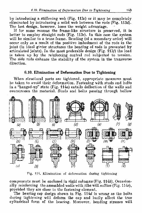
6.10. Elimination o f Deformation Due to Tiphteninp 145
by introducing a stiffening web (Fig. 113c) or i t may be completely eliminated by introducing a solid web between the rods (Fig. 113d). The last design, however, loses the weight advantage. -
If for some reasons the frame-like structure is preserved, i t i s better to employ straight rods (Fig. 113e). In this case the system will be similar to a truss frame. Bending (of a secondary order) will occur only as a result of the positive imbedment of the rods in the joint (in ideal girder structures the bending of rods is prevented b y articulated joints). In the most preferable design (Fig. 113f) the load is taken up by the reinforcing central rod subjected to tension. The side rods enhance the stability of the system in the transverse direction.
6.10. Elimination of Deformation Due to Tightening
When structural parts are tightened, appropriate measures must be taken to avoid their deformation. Fastening with studs and bolts, in a "hanged-up" state (Fig. 114a) entails deflection of the walls and overstresses the material. Studs and bolts passing through hollow
Fig. 114. Elimination of deformation during tightening
components must be enclosed in rigid columns (Fig. 114b). Occasion- ally reinforcing the assembled walls with ribs will suffice (Fig. 114c), provided they are close to the fastening element.
The bearing cap design shown in Fig. 114d is wrong as the bolts. during tightening will deform the cap and badly affect the true cylindrical form of the bearing. Moreover, bending stresses will

144 Chanter 6. General Deslen Princinles
occur in the bolts. In the design presented in Fig. 114e the cap is relieved from the tightening forces.
Figure 114f shows an incorrect and Fig. 114g, a correct fastening of a connecting rod cap.
If a pin is fastened as in Fig. 114h, the end eye lugs will be subjec- ted to bending. Fastening the pin to one lug with a dowel (Fig. 114i) alleviates the system from internal stresses, but deprives i t of rigi- dity. Reinforcing the eye lugs with a spacer bush (Fig. 1143') makes i t necessary to accurately keep to the spacer length and lug span width, thus complicating the manufacture. I t is more correct to tighten the pin in one lug (Fig. 114k), leaving the other end of the pin free for self-centring.
Mounting a roller in a yoke (Fig. 114 1) brings the fork lugs tow- ards each other as the bolt is being tightened and the roller loses its mobility. The introduction of a spacer bush (Fig. 114m) improves the situation but complicates manufacture. For the most correct alter- native (Fig. 114n) the pin is fixed in one lug only. The necessary end play enabling the roller to rotate freely is ensured by longitudinal clearance between the roller and lugs.
Figure 1140 illustrates a wrong and Fig. 114p, a correct tightening of flanges.
Fastening of a connecting rod in a yoke (Fig. 114q) requires accura- t e machining or exact fitting of the mating surfaces on both parts. Otherwise, either the yoke will be spread out by the rod, or the yoke will be bent as the bolts are tightened. In an improved design (Fig. 114r) the lower bolt is changed for a dowel pin working in shear. The eyes are bent (if clearance is present in the joint) only as a result of tightening the upper bolt, which, however, in this case will induce .less stresses than in the version shown in Fig. 114q. I n the design pictured in Fig. 114s the parts are fastened by means of dowel pins and are free of bending stresses. Yet, the joint lacks the capability of being tightened.
In terms of averaged indices of strength and rigidity the best alter- native seems to be that in Fig. 114r.
Figure 114t depicts a badly fixed bearing bush. The locking screw is driven to stop against the bush, thus deforming i t (shown by dashed line). In a correct design version (Fig. 114u) the screw head rests against the bearing body, with a clearance h being left between the thread and the bush.
An example of an erroneous tightening of a thrust washer juxtapo- sed onto a plain bearing end face is given in Fig. 115a. The shaft shoulder is insufficiently high; in the course of tihgtening the was- her is deformed by force P. To preserve the washer flatxless the shoul- der height must be increased and the diameter of the nut, decreased (Fig. 115b), or the washer must be given a stiff collar (Fig. 115c).
The defect of the gear fitted on aligning tapers (Fig. 115d) is that

6.10. Elimination of Deformation Due to Tightening 145
the tapers are positioned under the teeth which deform as the assem- bly is tightened (shown by dashed line). I n the correct design (Fig. 115e) the tapers are brought beyond the gear rim boundaries.
The design of a sealing unit with split spring rings (Fig. 115f) is bad. During tightening the housing crests are deformed and the
Fig. 115. Elimination of deformation during tightening
rings lose their mobility. Correct designs, free of rings seizure, are illustrated in Fig. 115g-i.
Occasionally a limited deformation is introduced in order to enhance the rigidity and stability of assembly. For example, when securing a column in a pedestal (Fig. 115j) a clearance h is lrft between the column flange and bearing surface. This clearance is taken up in the process of tightening. The amount of such a clearance is chosen either through calculations or experimentally so as to keep the stresses in the flange within safe limits.
Similar results can be obtained by making the flange bearing surface slightly tapered (Fig. 115k).
Sketched in Fig. 1151 is an assembly of a guide-vane unit and an impeller of a centrifugal pump. The vane ends are machined to a taper and they intima- tely close the impeller blades in tightening (Fig. 115m), thereby precluding blade vibration when running.
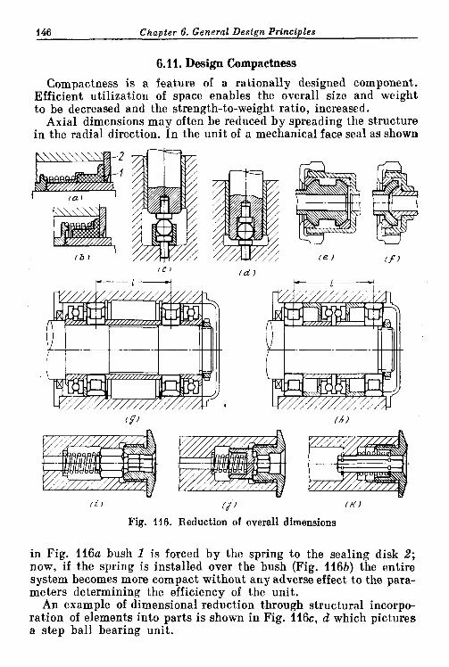
146 Chapter 6. General Design Principles
6.1 i. Design Compactness
Compactness is a feature of a rationally designed component. Efficient utilization of space enables the overall size and weight to be decreased and the strength-to-weight ratio, increased.
Axial dimensions may often be reduced by spreading the structure in the radial direction. In the unit of a mechanical face seal as shown
Fig. 116. Reduction of overall dimensions
in Fig. 116a bush I is forced by the spring to the sealing disk 2; now, if the spring is installed over the bush (Fig. 116b) the entire system becomes more compact without any adverse effect to the para- meters determining the efficiency of the unit.
An example of dimensional reduction through structural incorpo- ration of elements into parts is shown in Fig. 116c, d which pictures a step ball bearing unit.

6.11. Design Compactwess 147
In the spherical connection of a pipe unit (Fig. 116e) considerable reduction in dimensions is achieved by changing one of the external spherical surfaces to an internal spherical surface (Fig. 116f).
In the unit of a shaft end mounting loaded with alternating radial and axial forces (Fig. 116g) the axial load is taken up by two single- row thrust bearings. The design is cumbersome. The shaft fixing in the lengthwise direction is not accurate: the thrust bearings spa- ced a t a fair distance from each other must be installed with an axial clearance which compensates for temperature deformations; also axial backlash is unavoidable in this system.
In the design presented in Fig. 116h the axial load is taken up by a double-row thrust bearing installed between radial supports. The overall dimensions are decreased and the axial play minimized. Preserving the same dimensions as in Fig. 116h, one may increase the radial spacing of the supports 1.5 times, thus beneficially influenc- ing the shaft stability.
Figure 116i-k illustrates the design and operational improvement of a unit intended to lock an internal nut mounted on a shaft end. I n the original design (Fig. 116i) the nut is locked with a spring- loaded stopper provided with two hexagons, the larger one of which slides in the shaft hexagonal hole and the other smaller one enters the hexagonal bore of the nut. Unscrewing the nut should be preceded by sinking the stopper as this will bring the smaller hexagon out of engagement with the nut. The axial size of the unit is unreasonably large. The nut internal hexagon is brought to the nut end face so that a poorly experienced fitter may try to unscrew the nut without having released the stopper beforehand. As the stopper i s not fixed length- wise i t will drop out of the shaft hole during unscrewing.
Now, if the spring is mounted inside the stopper hexagon (Fig. 116j) the nut internal hexagon becomes shorter, thus preventing the nut unscrewing without preliminary release of the stopper.
In the most rational alternative (Fig. 116k) the stopper is made of a hexagonal bar. Hexagonal holes in the shaft and nut are machined by the same broach, whereas in the previous examples two different broaches were needed. Mounting the spring outside the stopper allows plan dimensions of the unit to be reduced 1.5 times as compar- ed with the original design. Here the stopper is fixed axially by means of a circlip and does not drop out of the hole after unscrewing the nut. The nut cannot be unscrewed unless the stopper is released.
Figure 117a illustrates a bevel gear unit in which the gear is in- stalled conventionally in a cantilevered mode. An improved design shown in Fig. 117b has two supports: one end of the driving gear shaft is installed in the casing wall and the other, in detachable cover I with a port provided in the area where the gears mesh. In this alter- native the size of the gears is decreased and their stability improved.
The axial size can be reduced to half that of the original construc- io*

148 Chapter 6. General Design Principles
tion if the gear is moved to the other side of the driving shaft (Fig. 117c).
Apart from the excessive overall dimensions, the bevel gear redu- cer sketched in Fig. 117d is inefficient in that i ts gears are mounted in various housing components and accurate engagement is therefore difficult to obtain. The accuracy of engagement can only be verified by blacking in.
I n the improved design (Fig. 117e) the housing volume is utilized in the most efficient way as the bearings of the major bevel gear are incorporated into the housing contour. One of the bearings of the minor gear is also located inside the housing. Further decrease of the overall dimensions has been reached through changing the gear key- type shanks to internal splines. All the bearings are housed inside a single component, this being very beneficial from the viewpoint of the accuracy of the bevel gears positioning. The design is unitized: after the cover is removed, the gear unit remains in place and is easily accessible for inspection and adjustment.
Figure 118 shows how the axial dimensions of a gear reduction unit can be reduced. I n the original design (Fig. 118a) end gear I is cantilever-mounted in diaphragm 2. The drive gear is mounted in two bearings, one of which is installed in cover 3 and the other, i n the end gear recess. This latter bearing is arranged in a cantileve- red way in relation to the main bearings. The intermediate gears shaft is supported a t one end in diaphragm 2 and a t the other, in cover 3. The axial dimensions of the system are unreasonably large. The sup- ports of the driving and intermediate shafts are located in different components. The bearing surfaces of the drive pinion cannot be machined together, this imposing higher demands for the alignment of the end gear shaft bearing surfaces. The assembly procedure of the unit is extremely complicated. As the diaphragm is fitted together with the cover the ends of the driving and intermediate gears shafts, which have previously been fixed each in i ts support, hang; the fitters are thus compelled to blindly place them into the second supports. In the improved version (Fig. 118b) the shafts supports are positioned within the shaped diaphragm 4 and tightened against cover 5. Owing to this feature the entire system becomes unitized. Now all the fitting surfaces can be machined in one setting with the diaphragm being screwed to the cover. The reduction gear unit can be assembled and checked as an individual unit. Any part of the unit is readily accessible for inspection during the assembly proce- dure. Axial dimensions are reduced by half as compared with the original design. This is achieved by the following measures (apart from the introduction of the detachable diaphragm):
the rim of the end gear drive splines (which in the previous design is machined on a separate fitted part) is made integral with the end gear as extension of the teeth;

Fig. 117. Reduction of overall dimensions of bevel gear drives
Fig. 118. Reduction of overall dimensions of gear drive I

150 Chapter 6. General Design Principles
the end gear is mounted on a needle bearing installed upon a cy- lindrical flange of the diaphragm; .
all the external splines of the input shaft are replaced by internal ones.
I n the alternative illustrated in Fig. 118c the gearing is mounted on a single component, namely, on diaphram 6. Cover 7 is non-bear- ing and is connected to the reduction gear mechanism only by the seal which encompasses the t ip of the driving shaft. I n this case manufacture and assembly are still more simplified.
6.12. Combining Design Functions
The overall size and weight of a structure can sometimes be decreas- ed materially by combining several functions in one component.
In a paired radial-thrust ball bearing intended to take up axial loads in both directions (Fig. 119a), the actual load is taken up by one of the bearings (at a given moment), while the other is idle.
In the single-row double-thrust ball bearing (Fig. 119b) the balls are encased in races which have deep grooves; for assembly convenien- ce the outer ring is split. When subjected to load the balls are forced against one side of the groove, leaving, accordingly, the opposite side. With a changed load direction the opposite groove is loaded. Such bearings of the same load capacity have half the axial length of the paired bearings. Furthermore, by encasing outer split races inside a common ring (Fig. 119c) the assembly becomes a unitized component.
Another example, similar to the above, is a helical ball drive (the system is very commonly applied in power drives). I n the alter- native depicted in Fig. 119d two balls are arranged in each helix, consequently, the axial load is taken up by one half of the total num- ber of balls only. If only one ball is installed is each helix (Fig. 119e) the axial load will then be shared by all the balls (regardless of the load direction), thus the load capacity is doubled.
In the rod journal joint of a two-part crank the connection is clam- ped with a bolt (Fig. 119f). In the improved version (Fig. 119g) the connection is accomplished by using the shank of the left-hand part of the crank.
In the flexible mounting of a gear rim on its hub (Fig. 119h) the alternating torque is transmitted from the gear rim via a number of springs mounted (in order to avoid distortion) on cylindrical inserts I resting in specially provided nests in projections 2, 3 of the rim and hub. Here one half of the springs damp the torque-induced vibrations in one direction, and the other half, in the opposite direction.
I n the improved alternative (Fig. 119i) the projections of the rim and hub are superimposed (in plan view); hub projections 4 are introduced into recess in the rim projections 5. Owing to such an
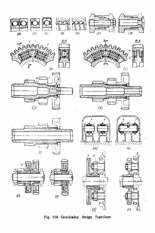
3 1 - A-A 0- 8 -
tt t-t
(9)
design functions Fig. 119. Combining

152 Chanter 6. General Design Princinles
arrangement all the springs take up torque-induced vibrations in both directions simultaneously. The unit is capable of transmitting doubled torque or damping vibrations whose amplitude is twice that of the previous system.
When mounting gears as shown in Fig. 119j, each gear is secured in place on its own splines. The small spline lengths encountered in the system forces the introduction of aligning elements, the cylindrical collars 6, 7 and 8. I n the design shown in Fig. 119k the gears are slipped onto one common spline. The result: special tools' list (broaches, hobs) is cut down by half; the assembly is simplified; the shaft strength, enhanced; the shaft right-hand journal diameter and the length of splines, increased, which enables the additional alignment of gears to be obviated.
I n the most perfect alternative (Fig. 1191) the gears are held on an extension of the pinion gear's teeth. The only special tool required is a broach for machining the splined holes.
In the unit of a valve drive mechanism (Fig. 119m) rockers 9 are mounted each on a stud of their own. I n the better version (Fig. 119n) both rockers are cantilever-mounted on a common pin.
Figure 1190 gives an example of gears mounted with intermediate spring coupling 10. In the alternative shown in Fig. 119p damping springs are arranged in the gear wheel of the drive. As a result the weight and axial dimensions are reduced and rigidity im- proved.
I n the planetary drive unit of a cam plate 11 (Fig. 110q) the satel- lites are mounted on an individual, in fact, superfluous part 12. In the improved design (Fig. 1 1 9 ~ ) the satellites are mounted directly on the plate. As a result, the unit becomes lighter and more compact and manufacture is eased.
\ 1
6.13. Equistrength
Some ways in which machine components can be imparted uni- form strength are illustrated in Fig. 120.
When a simply supported shaft is loaded with a transverse bending force (Fig. 120a), a body of equal bending resistance with the same maximum stresses in all sections will have the profile of a cubic pa rab~la (shown in the Figure by a thin line). The design in this case is not equistrong: the equal-resistance parabola is twice (on the shaft tapered section and beyond the cylindrical lug) outside the actual part contour. These sections are weak in comparison with the remain- ing ones.
In a correctly designed version (Fig. 120b) the parabola is contain- ed within the part contour. The through hole provided in the part hardly affects the strength, but considerably reduces the weight of the part.

Under complex loading conditionsl(Fig. 120c-f) the shaft undergoes bending from the force of the tooth drive and in the section between the teeth and splines which transmit the driving force the shaft is subjected to the action of operating torque M.
I n the design shown in Fig. 1% the shaft section is designed to meet maximum flexural and torsional stresses across AA , without
Fig. 120. Imparting equal strength properties to parts
considering the drop of the bending lqoment towards the supports- Also neglected is the fact that the shaft right-hand end is subjected to bending alone, whereas the left-hand end undergoes bending and torsion. Hence, the latter is loaded more severely.
In the equal-strength design (Fig. 1204 the shaft is made tapered, thus meeting accordingly the bending moment variation along the

154 Chapter 6. General Design Principles
axis. The equal strength of the left-hand (heavily loaded) and right- hand (lightly loaded) sides of the shaft is achieved by stepping the internal bore.
Equal strength can also be achieved by increasing the outer dimensions of the tapered portion m (Fig. 120e), or by decreasing the diameter of the right-hand ball bearing (Fig. 120f). Here the internal hole is again stepped but on the opposite side to the previous examples, accompanied also by an increase in the diameter of the left-hand support bearing.
The designs illustrated in Fig. 120d-f are equivalent, therefore, the design choice is dictated by technological and operational con- siderations.
I n a cluster gear (Fig. 120g) the gear teeth offer uneven resistance to bending and crushing. The circumferential force on the minor gear rim will under any conditions (i.e., with multiplying and reducing gear ratios) be less than that on the major gear rim by a factor equal to their diametral ratio. The design can be made more balanced in strength if the width of the major gear teeth is decreased (Fig. 120h) even though not strictly in proportion to the acting forces (with due regard for the higher circumferential speed).
In a bar bracket loaded with a tensile force (Fig. 120i) the middle bar carrying the greater portion of the load is overloaded in compari- son with the lateral, slightly loaded bars. The system becomes equally strong if the middle bar cross-section is increased (Fig. 1203').
For units to have equal strength means that all their parts must have equal stresses (for similar materials) or possess equal strength ,(for materials of different strength). The design version of a splined joint illustrated in Fig. 12ia has a non-uniform strength on two co- unts: the strength of shafts in plain sections (diameter d) is much more better than that across the splined part (diameter do); the splin- ed bush has a considerably higher resistance to torsion than the shafts.
The equal-strength condition requires that both the bush and the shafts have equal resisting moments in torsion: 0.2D3 (1 - a4) = 0.2a3, where a = d / D . For the relationships in the Figure ( a = 0.68) the strength
1-ad- of the bush is - - 2.5 times greater than that of the shafts.
a3
In a rational design (Fig. 121b) the diameter of the shafts is reduced i n comparison with the internal diameter of the splined joint and the external diameter of the bush (D') is reduced to the technolo- gically acceptable minimum value.
In the connection of a screw propeller blade (aluminium alloy) with a steel hub (Fig. 121c) the predominant stress is that of tension produced from the centrifugal farce as the propeller rotates. The design has unequal strength. The thread profile both a t the blade

root and in the hub is the same although the permissible stresses in bending and shear for aluminium alloy are lower than those for steel.
In the design shown in Fig. 121d the height (in the axial direction) of the blade threads is made higher than that of the bush so as to render them equally strong. The bush is given a shape offering equal resistance to tension. The bush cross-section progressively increases
Fig. 121. Imparting equal strength properties to units
downward coping accordingly with the rising tension forces transmit- ted to the bush by the blade threads. A relieving recess is made in the blade.
The square-profiled toothed-slot fastening of turbine blades in the rotor (Fig. 121e) is irrational for two reasons. First, the blade root is uniform in thickness and therefore is not equally strong. The full centrifugal force is taken up by the cross-section lying nearest to the blade root platform and this section is overloaded as com- pared with the other sections in which the acting force progressively decreases towards the root tip. The picture is opposite in the rotor webs, where the most severely loaded section lies close to the root tip, while the above-lying sections are loaded to a lesser degree.
Secondly, because of the square-shaped teeth the material of the root is not utilized to i ts best. The total section working in shear and flexure is approximately equal to one half of the root section (over height h).

156 Chapter 6. General Design Principles
The entire root height can share the load if the teeth are made triangular (Fig. 121f) or trapezoidal (Fig. 121g). In this case the tooth shear strength improves approximately twice and the flexural strength, 4 times. Trapezoidal teeth have an additional advantageous feature, namely, lower bearing stress on the teeth working faces,
I n the most rational version (Fig. 121h) the root is wedge-shaped, thus coping with progressively decreasing forces acting upon the root. Such a shape increases the critical sections of the blade root and rotor webs about 1.5 times, with a corresponding increase in the joint strength.
6.14. Uniform Loading of Supports
When designing units with antifriction bearings, the latter shoulcl advisably be made of equal durability.
Let us consider an example of a gearing (Fig. 122a). The drive load P1 on the pinion exceeds load P 2 on the gear by a factor of D21Dlzw
Fig. 122. Imparting equal durability to supports
m 4. With the supports spaced as in the Figure, the left-hand bear- ing is loaded with force N, which is 2.5 times greater than force N 2 acting upon the right-hand bearing. The supports can be made of equal durability if on the shaft right-hand end is mounted a smal- ler bearing (Fig. 122b) whose load capacity is 2.5 times less than that

6.15. Self-Alignment Principle 157
af the left-hand bearing. If in the interests of unification it is still preferable for both bearings to have the same size, then the position af the supports relative to the acting forces should be altered so that the load on both bearings is the same (Fig. 122c).
I n a cantilevered impeller unit of a centrifugal compressor (Fig. 122d) the shaft is acted upon by radial force P1 (resulting from impeller imbalance) and axial force P , (from the operating fluid). The design is inefficient. The front (nearest to the impeller) bearing is loaded b y a large radial force Nl and axial force P,, while the rear bearing is loaded by a very small radial force N,. I n the version shown in Fig. 122e the axial force is taken up by the rear bearing, this result- ing in more uniformly distributed bearing loads. The alternative illustrated in Fig. 122f has i ts shaft mounted in different bearings whose capacities are consistent with the acting loads.
6.15. Self-Alignment Principle
In sliding mechanical connections, where distortions and deflec- tions are possible, preliminary thought should be given to free self- alignment so that the connection works correctly with all assembly and manufacturing inaccuracies.
The most simple example is a toe bearing. If the bearing plate is rigidly mounted in the housing (Fig.123~) the toe edges will work aver the plate due to which distortions are inevitable in the system. In the design shown in Fig. 123b the plate is placed on a spherical support, which assures intimate contact along the entire friction surface, thus increasing loading capacity and durability.
The self-alignment principle is extensively used when designing shaft supports subjected to bending and distortion. Self-alignment is particularly important for plain bearings with great length-to-dia- meter ratios. If the mounting is rigid (Fig. 123c) the shaft's bending and distortion causes higher edge pressures thus sharply worsening bearing operating conditions. To enable self-alignment the bearings are installed on spherical supports (Fig. 123d).
In radial ball bearings (Fig. 123e) shaft flexure distorts the bear- ing and unilaterally loads the balls by a value which may exceed the designed load. The defect can be eliminated by placing the bearing into a spherical ring (Fig. 123f) or by applying double-row spherical bearings (Fig. 123g).
I t should be noted that double-row spherical bearings have lower load capaci- ties than the single-row radial bearings (due to the outer race shape which i s unfavourable to contact, strength) and cannot withstand large axial forces. For this reason when des i r ing unit? intended to receive higher axial loads i t is better to employ sing e-row bearings on spherical supports or doubIe-row self-aligning bearings with barrel-shaped rollers.

158 Chanter 6. General Desirn Prineinles
Another example - a two-stage air compressor piston (Fig. 123h). Piston I slides in a low-pressure cylinder, while the rod slides in a high-pressure cylinder (air passages are not shown in the Figure). The defect of the system is that the piston and rod are made as one. This means that accurate alignment of working surfaces is necessary,
Fig. 123. Imparting self-alignment properties
i.e., those of the piston and rod on one hand and bores of the high- and low-pressure cylinders on the other. Since the clearance between the rod and high-pressure cylinder walls is much less than that bet- ween the piston and low-pressure cylinder walls, transverse drive forces are taken up mostly by the rod, which causes i ts excessive wear.
In the advisable design (Fig. 123i) the rod can deflect and move about the piston axis as i t is separated from the piston. The drive forces are taken up by the piston, and the rod is relieved of transverse loads. Thus, rigorous alignment of the bores of the low- and high- pressure cylinders is now not necessary.
The plate valve design (Fig. 1233') in which the plate is positively fixed to the stem end fails to assure leak-tight valve-to-seat contact

6.15. Self-Alignment Principle 159
because of the inevitable non-perpendicularity of the seating sur- face in respect to the stem axis. Another mistake is that during clo- sure the plate rotates together with the stem relative to the seat. The latter error is eliminated in the design in Fig. 123k where the plate i s fixed to the stem end by means of two transverse pins I. As the valve is being closed, the stem rotates relative to the plate, however, a tight valve seating is still not achieved.
I n the correctly designed version (Fig. 1231) the stem end is made spherical, owing to which the plate can freely self-align and seat tightly regardless of the manufacturing inaccuracies. The free self- alignment is due to clearance s between the transverse pins and the stem end shoulder.
A f lap which alternately closes two pipes, square to each other (Fig. 123m) cannot closely seat, especially as the pipes have soft gaskets which can appreciably alter pipe positions during reassem- blies. In the correct design (Fig. 123n) the flap is mounted on a sphe- rical pivot 2. Moreover, i t is locked endwise with transverse pins 3 and prevented form rotation about the stem axis by placing the pins in shallow holes in the stem.
In the clamp illustrated in Fig. 1230 the clamping effort is taken, in fact, by one point of the rifled surface. Hence, the fastening bolt thread is subjected to bending.
The design version in Fig. 123p is free from distortions in all i t s links. The articulated bolt also adds to the convenience in operation.
Sketched in Fig. 124 is a wedge-type gate shutting off coaxial pipes. When the gate is rigidly fastened to the driving rod (Fig. 124a) i t cannot be simultaneously pressed tightly against both seats; the gate self-alignment is only possible with clearances in the system and flexible deformation of the rod.
A somewhat better design is shown in Fig. 124b, in which the gate can freely move relative to the rod thanks to a cylindrical hinge. Here any inaccuracy in the rod position relative to the seat will in no way impair the functioning of the system. However, manufacturing inac- curacies between the gate and seat tapered surfaces, axial misalign- ments and pipe distortions, pipe angular displacements in the plane normal to the axis, etc., are not considered.
Figure 124c shows a gate composed of two halves coupled to each other and to the driving rod by a cylindrical pin. To preclude spon- taneous opening of the halves with the gate up, distance springs are incorporated between the halves. The problem has been solved but partially, because the gate halves can self-align in the plane of rota- tion about the axis only and not in the plane running normally t o the pipe axis. This drawback is eliminated by making the pin-receiv- ing holes in the rod and eyes oval-shaped. Then (Fig. 124d) self- alignment is ensured in any direction (within the clearance between the pin and hole walls).


t-t 7 /A )
Fig. 125. Levelling out loads an gear teeth (a-c) planetary gearings; (d-f) multitrain gearings
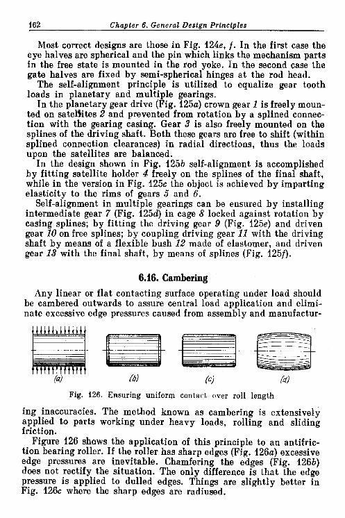
162 Chanter 6. General Destan Prtnctnles
Most correct designs are those in Fig. 124e, f . I n the first case the eye halves are spherical and the pin which links the mechanism parts in the free state is mounted in the rod yoke. In the second case the gate halves are fixed by semi-spherical hinges a t the rod head.
The self-alignment principle is utilized to equalize gear tooth loads in planetary and multiple gearings.
In the planetary gear drive (Fig. 125a) crown gear 1 is freely moun- ted on satellites 2 and prevented from rotation by a splined connec- tion with the gearing casing. Gear 3 is also freely mounted on the splines of the driving shaft. Both these gears are free to shift (within splined connection clearances) in radial directions, thus the loads upon the satellites are balanced.
In the design shown in Fig. 125b self-alignment is accomplished by fitting satellite holder 4 freely on the splines of the final shaft, while in the version in Fig. 125c the object is achieved by imparting elasticity to the rims of gears 5 and 6.
Self-alignment in multiple gearings can be ensured by installing intermediate gear 7 (Fig. 125d) in cage 8 locked against rotation by casing splines; by fitting the driving gear 9 (Fig. 125e) and driven gear 10 on free splines; by coupling driving gear 11 with the driving shaft by means of a flexible bush 12 made of elastomer, and driven gear 13 with the final shaft, by means of splines (Fig. 125f).
6.16. Cambering Any linear or flat contacting surface operating under load should
be cambered outwards to assure central load application and elimi- nate excessive edge pressures caused from assembly and manufactur-
Fig. 126. Ensuring uniform contact over roll length
ing inaccuracies. The method known as cambering is extensively applied to parts working under heavy loads, rolling and sliding friction.
Figure 126 shows the application of this principle to an antifric- tion bearing roller. If the roller has sharp edges (Fig. 126a) excessive edge pressures are inevitable. Chamfering the edges (Fig. 126b) does not rectify the situation. The only difference is that the edge pressure is applied to dulled edges. Things are slightly better in Fig. 126c where the sharp edges are radiused.
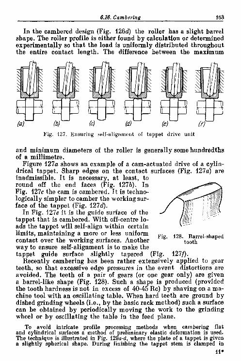
6.16. Camberina 163
In the cambered design (Fig. 126d) the roller has a slight barrel shape. The roller profile is either found by calculation or determined experimentally so that the load is uniformly distributed throughout the entire contact length. The difference between the maximum
Fig. 127. Ensuring self-alig~~ment of tappet drive unit
and minimum diameters of the roller is generally some hundredths of a millimetre.
Figure 127a shows an example of a cam-actuated drive of a cylin- drical tappet. Sharp edges on the contact surfaces (Fig. 127a) are inadmissible. I t is necessary, a t least, to round off the end faces (Fig. 127b). I n Fig. 127c the cam is cambered. I t is techno- logically simpler to camber the working sur- face of the tappet (Fig. 127d).
In Fig. 127e i t is the guide surface of the tappet that is cambered. With off-centre lo- ads the tappet will self-align within certain limits, maintaining a more or less uniform Fig. 128. Barrel-shaped contact over the working surfaces. Another tooth way to ensure self-alignment is to make the tappet guide surface slightly tapered (Fig. 127f).
Recently cambering has been rather extensively applied to gear teeth, so that excessive edge pressures in the event distortions are avoided. The teeth of a pair of gears (or one gear only) are given a barrel-like shape (Fig. 128). Such a shape is produced (provided the tooth hardness is not in excess of 40-45 Rc) by shaving on a ma- chine tool with an oscillating table. When hard teeth are ground by dished grinding wheels (i.e., by the basic rack method) such a surface can be obtained by periodically moving the work to the grinding wheel or by oscillating the table in the feed plane.
To avoid intricate pr~fi le recessing methods when cambering flat and cylindrical surfaces a methoB of preliminary elastic deformation is used. The technique is illustrated in Fig. 129a-d, where the plate of a tappet is given a slightly spherical shape. During finishing the tappet stem is clamped in
11*

164 Chapter 6. General Design Principles
a cylindrical arbor, which causes the plate to camber inwards and assume the shape exaggeratedly illustrated in Fig. 129b. The working surface is tben ground flat (Fig. 1 2 9 ~ ) and after the tappet is detached from the arbor, the plate
Fig. 129. Cambering procedures
straightens anti assunscs a slightly outward-cambered shape (Fig. 129d). The amount of conve-;ity is controlled by the arbor tightening force.
A similar cambering technique as applied to a roller is pictured in Fig. 129e-h. Another method is based on the application of a strictly controlled load to the
finished part, which induces therein residual deformations of the required level.
6.17. Effect of Elasticity upon Load Distribution
Elastic deformations substantially influence load distribution and the magnitude and distribution of stresses in the body of the part. The directions of elastic deformations in the part must be preci- sely known and used to lower the stresses and balance the loads.
As an example Fig. 130a presents a splined connection unit of a gear and shaft. The gear disk is displaced relative to the splines. The torque transmitted by the gear is taken up mostly by the part of splined connection positioned a t the rigidity node, i.e., in the disk plane. The qualitative picture of the bearing stress distribution over the splines working face is presented by the curve. Obviously, the stresses reach their maximum in the disk plane and are insignifi- cant over most of the spline length. If the splines rim is inverted (Fig. 130b), the torque from the shaft end twists the shaft. As a result, the splines on the left of the gear come into close contact with the hub splines over their entire length and also twist the hub. Thus, the torque is transmitted more uniformly throughout the con- nection. In some measure the system exhibits self-levelling properties:

6.17. Effect of Elasticity upon Load Distribution 165
the greater the torque and, hence, the shaft twist, the more uniform is the load distribution along the splines.
In the press-fitted connection (Fig. 130e) the pressure on the con- tacting surface is concentrated lpredominantly at the:rigidity node, i.e., in the plane of the fitted disk. The pressure can be distributed more uniformly by placing the disk centrally and by 'reinforcing the hub with ribs (Fig. 130d).
Another example of using elasticity to level out force distribution is given by the seating of a column into i ts pedestal. With the usual design (Fig. 131a) the bulk of the load is applied a t the rigidity node, namely, a t the transition section where the flange meets the column body.
If the flange support surface is made slightly conical (Fig. 131b), the flange rim will first touch the bearing surface and then, during tightening, will elastically deform and distribute the tightening force more uniformly over the bearing surface. The joint, as a whole, obtains greater rigidity and steadiness.
Figure 131c, d shows a method of strengthening the fastening of a turbine blade in a fir-tree-shaped rotor slot. In the design shown in Fig. 131c the working surfaces of the blade's trapezoidal teeth, taking up centrifugal force P, in the initial position contact the rotor slots thrust faces. With the centrifugal force applied the blade root exte- nds, while the rotor body deforms to a lesser degree, thanks to its greater rigidity. Due to this the load is taken mainly by ;the first teeth (see the curve).
In Fig. 131d the blade teeth fit the slots with clearances hl, h, and h, which increase successively from the root to the blade plat- form. As the blade extends, the working surfaces of the teeth succes- sively contact the rotor slots thrust faces, thus a more even load distribution among the teeth results and, consequently, the connec- tion becomes stronger.
In practice, when dealing with fir-tree-shaped connections, allowances should be made for thermal deformations due to the non-uniform blade heating in the interblade rotor sections and for the creep of the blade root.
In conventional threaded connections (Fig. 132a) the thread load distribution is uneven. This condition is aggravated by the fact that the elastic deformations of the bolt and nut differ in direction; the bolt elongates by a value fl under the action of tightening forces and operating loads and the nut contracts by a value f,. As a result, the first threads of the bolt (from the nut bearing surface) under load tighten onto the first threads of the nut (Fig. 132b) and take up most of the load. Both theoretical and experimental data proves that the first thread carries approximately 30% of the total load.
Recently efficient methods have been devised which enable the load to be equalized throughout the thread by correcting the thread
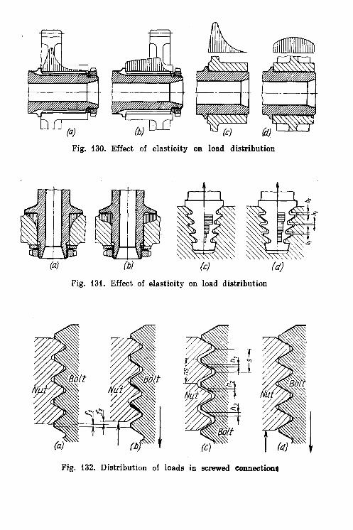
Fig. 130. Effect of elasticity on load distribution
Fig. 131. Effect of elasticity on load distribution
Fig. 132. Distribution of loads in screwed connection8

6.17. Effect of Elasticity upon Load Distrtbutlon 167
geometry. The simplest of these methods consists in making the nut thread pitch larger than that of the bolt by a factor that depends on the magnitude of the acting force established either by calculations or experimentally. On the average this factor varies from 1.002 to 1.004. In screwed connections with usual pitches (1-2 mm) the dif- ference between the nut and bolt pitches is 3-5 pm. Furthermore, increased radial clearances are provided in such connections in order to ensure self-alignment of the nut relative to the bolt and the bear- ing surface. In the free state the bolt topmost thread contacts the topmost thread of the nut (Fig. 132c) and progressively increasing axial clearances h,, h, and h, are formed between the adjacent threads. As soon as a load is applied, the bolt elongates and the nut
Fig. 133. Nut designs
contracts, thus the bolt threads tighten successively onto the threads of the nut (Fig. 132d). With a correctly chosen pitch difference the load will be taken up by all the threads. Uniform loading can be assured only a t a certain design magnitude of the force acting on the joint. But even with forces close to the above the load is dist- ributed more evenly along the threads than with threads of the same pitch.
Another method is based on reversing the direction of the nut deformation. If the threaded section is subjected not to compression (Fig. 133a) but to tension (Fig. 133b), then the first nut threads acted upon by the load shift in the same direction as those of the bolt. As a result, the load is distributed more uniformly over the threads. Such nuts are called tension nuts.
In a semi-tension nut (Fig. 133c) the bearing surface is positioned approximately in the middle of the screwed section whose lower part takes up tensile stresses. To involve into efficient use the upper threads, i t is necessary to utilize the effect of elastic deformation of the nut upper portion. The forces acting upon the bearing surface cause a radial deformation of the nut body (in the direction shown by light arrows) and, as a result, squeezing of the upper bolt threads. Today both tension and semi-tension nuts are widely used in criti- cal screwed connections.
The profile of a tension nut with a uniformly distributed load is determined proceeding from the following considerations. Let the len th of the threaded nut section be h (Fig. 134a). For uniform distribution of t%read load the tensile force acting upon the nut in any section at a distance x from the thread start

168 Chanter 6. General Design Principles
must be x
Pnut = P - b (6.8)
where P is the force applied to the bolt. The tension force acting upon the bolt in the same section
For deformation compatibility the relative elongation of the nut in any section must be equal to that of the bolt
Pnat - - Pbolt EnutFnut Ebo~tFbolt
(6.10)
where Fnut, Fbolt and Enut, Ebolt are the cross-sectional areas and moduli of elasticity for the materials of the nut and bolt, respectively.
Fig. 134. Determination of tension nut profile
Substituting in Eq. (6.10) the values of PnUt and PboIt from Eqs. (6.8) and (6.9), we obtain -
If the nut and bolt are made of same material (EnUt = Ebolt)
Substituting in Eq. (6.11) tpe values Fbolt = U.785d2 and Fnut = 0.785X X(D2 - @),where d is the bolt dlameter and D running external diameter of the nut, we get
(6.12)
When s = h, diameter D = w. Obviously, this condition can only be approximated. For any finite nut
diameter (where theithread plane finishes) the upper threads will be loaded more than thei lower ones.
Uniform distribution of thread loads can be achieved by increasing the bolt end compliance. Let a conical recess be made in the bolt [stem (Fig. 134b) SO that its peak begins in the same plane as the thread. The running diameter 6 of the recess is
x 6 = d -
h
where d is the initial recess diameter (assumed to be equal to that of the bolt).

6.17. Effect of Elasticity upon Load Distribution 169
The running cross-sectional area of the bolt is
' F b l t = 0.785 (d2- fP) = 0.785~9
Substituting this relation in Eq. (6.11) gives
(6.13)
When z = h, diameter D = d l / g = 1.73d. This nut shape can be realized in pactice. The cross-section of the nut above thc threaded portion is determined from
the equal strength condition for the nut and bolt in tension
K u t = Fbolt (6.14) Let the diameter of the recess in the nut above the threaded portion be 0,
Then, according to Eq. (6.14) 0.785 [(1 .73d)2- 021 = 0.785d2
whence 0 = d l / Z = 1 . 4 1 d
Figure 134c shows a design approximation of the theoretical nut and bolt shapes, where the load is uniformly distributed alongithe threads.
Figure 135 illustrates how a heavily loaded screwed connection (namely, a propeller blade fastening unit) can be rationally redesign- ed.
The factor of elasticity must necessarily be taken into conside- ration when designing bearing units. Figure 136a, b shows a paired installation of antifriction bearings. In Fig. 136a the greater part of the load is taken up by the bearing positioned in the ri- gidity node (housing wall plane). The other bearing mounted at the hub end is lightly loaded because of the hub being compli- ant. The bearing loads can be ( a ) ( 3 i
evenly distributed (thus contri- Fig. 135. Reinforcement of propeller buting to a better load-carrying blade fastening capacity of the unit as a whole) if the hub end is stiffened with another web (Fig. 136b).
Another example of elasticity utilization is given in Fig. 136c in which the bearings are installed in a thin-walled steel bush. Thanks to the elasticity of the bush the system can adapt itself to shaft distortions, and resembles a system which has bearings mounted in a spherical support.
Thus, by utilizing elasticity one can obtain optimum distribution of load between bearings. In the bearing unit loaded with radial

170 Chapter 6. General Design Principles
force P and unilateral axial load Q (Fig. 136d) it is better to distri- bute the load according to the bearings function: one of the bearings should be loaded with the radial force and the other, with the axial
Fig. 136. Effect of housing elasticity on load distribution in paired bearing installation
force. This can be realized by mounting the bearings in an elastic cantilever-type bush. Bearing 1 located in the rigidity node (i.e., in the fastening flange plane), takes the radial load. Bearing 2, mounted a t the cantilever end receives axial load only,
6.18. Fitting to Several Surfaces
I t is good practice to avoid, whenever possible, fitting parts to several surfaces (Fig. 137a, b). As a rule, parts should be fitted to one
Fig. 137. Matching of surfaces
surface, while for other surfaces clearances h (Fig. 137b, d) must be provided. These clearances must be sufficient to exclude contact of surfaces! under the conditions of any possible inaccuracy of produc-

6.19. Tightening ua on Two Surfaces 171
tion, elastic deformations, thermal expansion of the system or under compression of sealing gaskets,
Rough errors, like those sketched in Fig. 137a, c, are only charac- teristic of inexperienced designers. Still more typical errors include superfluous fitting or alignment, etc. For example, fitting a prisma- tic loose key throughout the entire contour of the keyway (Fig. 137f) will heavily, and, which is still more important, quite unnecessarily complicate the production. I t is more reasonable to f i t the key to the working edges only, providing clearances on the key end faces, as well as between the key top surface and the keyway bottom (Fig. 137g, h).
6.19. Tightening Up on Two Surfaces 1-'Occasionally it may be necessary, due to some design features,
&tighten a unit of two surfaces. Figure 138 (tightening three flan- ges) reviews techniques applied under these conditions.
Simultaneous and uniform tightening of all surfaces (Fig. 138a) presumes] that the end flange faces should be machined together
Fig. 138. Tightening against two surfaces. Fastening of intermediate flange
and fitted or have undergone extremely accurate manufacture. if a flange protrudes from its recess (Fig. 138b), an interference may occur and the tightened part will bend. On the other hand, if the flange is'sunk in i ts recess (Fig. 138c), the flange axial fixing will be lost.
The introduction of elastic gaskets (Fig. 138d-f) improves the design and seals the joint if the gasket is sufficiently thick and flexible and overlaps non-flush sealing surfaces.
Whenever the good sealing and accurate axial fixing of a flange are necessary, i t is recommended to employ gaskets of some soft metal (red copper, lead, aluminium, etc.) whose thickness exceeds the depth ,of the recesses where the gaskets are to be fitted. During

172 Chapter 6. General Design Principles
tightening the metal gasket plastically deforms (Fig. 138g), seals the joint and fixes the flange. Some space must be provided to enable excessive metal to freely flow out. The bearing stresses arising in
the gasket under the action of working axi- al forces must be below the yield point of the gasket material. Otherwise, accurate axial fixing will be lost.
If harder metals (brass, bronze, low-car- bon annealed steel) are used for the gask- ets, these must be made corrugated or comb-like (Fig. 138h) to assure plastic defor- mation. Spring gaskets (Fig. 138i, j ) are also applied. '
Figure 139 shows two-piece crank conne- cted in a main journal by means of trian-
Fig. 139. Tightening gular-shaped end-face splines, an antifri- against several surfaces. ction bearing being simultaneously clamped Two-part crank journal between the two parts of the crank. hThe
tightening of the splines and inner bearing race in this case is ensured on the account of the deformation of metallic rings 1 placed on either side of the inner race.
6.20. Axial Fixing of Parts Parts must be fixed axially a t dne point so that they can freely
self-align throughout their length. If, for instance, a pin is fixed by self-tapping screws a t both supports (Fig. 140a) then additional stresses are likely to occur as a result of thermal dimensional changes. In the correct design shown in Fig. 140b only one end of the pin is fixed, while the other end is free to move in i t s support.
In the badly designed herringbone gearing (Fig. 140c) the lower gears are fixed in position twice: by their teeth and stops m. To obtain the complete coincidence of fixing positions is impossible. The error can be eliminated by providing clearances s, which assures gear self-alignment by their teeth (Fig. 140d).
The gear shaft mounted in plain bearings (Fig. 140e) is fixed in two points spaced far away from each other.
Accurate fixing in this case is impossible because a large clearance must be provided between fixing surfaces in order to avoid seizure of bearing surfaces due to thermal expansion of the housing. Further- more, due account must be taken of the inevitable inaccuracies of manufacture and assembly due to the required clearances between mounting surfaces.
The design is somewhat improved by bringing the fixing surfaces closer together (Fig. 140f). I n the correct designs (Fig. 140g, h) the shaft is fixed over a short distance (in the design presented in Fig.


174 Chapter 6. General Design Principles
140h it is fixed practically in one plane); the other end of the shaft is allowed to self-align in i ts support.
Free areas of parts must be given certain margins for self-align- ment and compensation for manufacturing dimensional inaccura- cies. Let us consider the case of a shaft installed inside a housing on antifriction bearings. In the design illustrated in Fig. 141a the axial dimensions, predetermining the mutual location of the shaft, bear- ings and housing, are held to the nominal size. I n the alternative
Fig. 141. Introducing margins on fitting surfaces
pictured in Fig. 141b the following clearances are provided: m - on the fitting surface of the housing to suit the floating bearing; h- on the fitting surface of the housing relative to the fixing stop rings; k-in the thread for the fastening nut; n-on the fitting surface of the shaft to suit the floating bearing.
The clearance values are found by calculating the dimensional chains and thermal expansions in the system. The maximum clear- ances should be provided in the areas of transitions to black cast surfaces where dimensional variations are particularly great (for medium-sized castings of moderate accuracy such clearances are taken a t 3-4 mm).
6.21. Control of Direction
Parts reciprocating linearly along two guideways should be guided along one way only, the other guide only supporting the part (Fig. 142b, d). A simultaneous guiding along two ways (Fig. 142a,c) means much more stringent machining requirements to the guides and ways. Any change in temperature conditions may impair orientation and, hence, the part may seize in i ts guideways.

6.22. Mounting Surfaces 175
If the use of two guideways is inevitable, their manufacture must be simplified as much as possible. In a design with two guiding rods (Fig. i43a) the necessity to accurately keep the centre distance bet- ween the rod sockets in the driven part and the guiding holes in the
Fig. 142. Guiding of parts (a) and (a) wrong; (b) and (d) correct
housing can be eliminated by increasing the diameter of the sockets (Fig. 143b) and fixing the rods in their sockets after aligning them with the guiding holes. Another method consists in machining the
Fig. 143. Ensuring accurate guidance over two surfaces
rod sockets and guiding holes together. In this case the diameters of the guiding holes and the rod sockets must be the same (Fig. 143c). However, different fits for the rods are required, namely a sliding fit in the housing and an interference fit in the rod sockets.
6.22. Mounting Surfaces
Generally speaking, any mounting surface for detachable parts should be flat. Fastening on cylindrical surfaces should be avoided (Fig. 144a). The manufacture of such connections is labour consuming. The fitting surface of the detachable component must be machined in a fixture to assure the equality of the diameters of the mounting surfaces on the part and housing and i t is rather difficult to uni- formly tighten angularly-spaced bolts. The correct design with a f lat mounting surface is pictured in Fig. i44b .
Sometimes it may be necessary to fasten parts to surfaces position- ed a t an angle to one another (Fig. 144c).P The connection seems strong and rigid. I t s manufacture, however, is difficult as it is

176 Chanter 6. General Desian Princinles
absolutely necessary to keep the angular equality between the fitted part and housing to preclude the deformation of the part during fastening. Fastening bolts must be alternately tightened and each time by small amounts in order to assure the close fitting of the part to both mounting surfaces. Obviously, a design with a plane mount- ing surface is much more preferable (Fig. 144d).
Flat attachment is of particular importance when air-tight con- nections have to be obtained. Sealing surfaces must be free of any
Fig. 144. Clamping on curved surfaces
steps, as well as of outer or inner corners. Fitting to curvilinear sur- faces is inadmissible. An example is presented in Fig. 144e, which shows a cover enclosing an angular space in a housing. The design has two defects. First, i t is practically impossible to seal off the space end walls forming reentrant angle a. Secondly, the proper tightening of the cover is made impossible by the fact that screwing up one row of bolts will interfere with screwing up the other row of bolts. The latter of these two defects is eliminated in the design pictured in Fig. 144f where the cover is tightened up by a row of diagonally arranged bolts. This technique is rather common in fastening shields over spaces which do not require sealing, and also when enclosing through tunnels. Should the air-tightness be necessary, the only correct solution will be that illustrated in Fig. 144g where the cover is fitted on a flat surface.
Also erroneous is the design of a cover intended to enclose a hatch in the corner of a welded sheet-steel housing (Fig. 14&), since i t is practically impossible to provide close tightening over a curvi- linear surface even when using a thick gasket. A correct design sketched in Fig. 144i incorporates a flat frame welded to the hatch and forming a flat fitting surface.

6.23. Butt-Jointing on Intersecting Surfaces 177
6.23. Butt-Jointing on Intersecting Surfaces
Butt-jointing on intersecting surfaces complicates the manu- facture and sealing of joints.
An incorrect joint design is pictured in Fig. 145a. Here the side cover 1 is mounted upon the joint of the housing and the upper
Fig. 145. Fitting on intersecting surfaces
cover, which means that its fitting surface must be machined after the assembly of the housing and the upper cover, and to assure the tightness of the joint, a thick elastic gasket must be used. In
Fig. 146. Methods of fastening split housings
the correct design shown in Fig. 145b the housing-to-upper-cover joint is moved beyond the side cover.
A non-technological design is that of a housing made up of two halves joined in vertical plane AA (Fig. 145c). The upper cover is mounted on the joint of the halves. Still worse i s the design in Fig. 145d where the cover i s joined with the housing halves in two mutually perpendicular planes. In the correct design (Fig. 145e) the joint surfaces are separated.
Figure 146a shows a rotor machine housing split in the horizon- ta l plane with two end covers also split horizontally, which makes the joint sealing difficult. The slightly improved version in Fig. 146b has solid end covers. The best designs have either a housing and covers (Fig. 146c) joined in vertical planes (axial assembly), or a housing (Fig. 146d) split in the horizontal plane (radial assembly).

178 Chanter 6 . General Design Princinles
6.24. Interchangeability of Rapidly Wearing Parts
I t is good practice to manufacture any rubbing or rapidly wearing part of a machine component as an easily interchangeable piece. The latter can be made of a material with special properties which are absent in the basic material of the component.
Figure 147a illustrates a T-slot made in the body of a cast-iron bed. To provide for machining convenience, longer service life
Fig. 147. Introduction of replaceable parts
and changeability i t is advantageous to make the T-slot as a sepa- rate piece from some durable material and to fasten i t to the bed, e.g., in a slot (Fig. 147b).
To ensure reliable operation of the threaded pair in an inter- nally threaded steel rod for a lead screw (Fig. 147c), i t is advisable to use a bronze bush (Fig. 147d) which possesses antifriction pro- perties and can easily be changed.
Figure 147e illustrates an erroneously designed seal with split spring rings fitted in shaft grooves, the external cylindrical sur- faces of the rings sealing against the housing. When the grooves in the shaft and the hole in the housing get worn, both these expen- sive components have to be rejected. In the correct design (Fig. 147f) the rings are assembled in a changeable bush and work in a sleeve made from a harder material.
When installing an antifriction bearing in a light-alloy housing (Fig. 147g) the seating surface rapidly crushes during operation. Machining the hole even slightly oversize causes the rejection of

6.25. Accuracu o f the Altenment o f Parts 179
the entire housing unit. I t the correct design (Fig. 147h) the bear- ing is installed in an intermediate bush made from a harder mate- rial, which reduces the seat wear and enables defective housings to be rectified.
To install the valve of an internal combustion engine in the manner depicted in Fig. 147i, i.e., directly in a cast iron head, is bad practice. I t is better to install the valve in a guide bush made of a harder material (Fig. 1471) and introduce an insert-type seat of a heat-resistant material.
Figure 147k-m shows a water-cooled engine block. If the cylinder working surfaces are machined directly in the cast block (Fig. 147k) t,he design is bad. To obtain high-quality mirror-finish bores in a large casting is difficult. Furthermore, the cylinder walls may have defects (blisters, voids, pits, etc.) which sometimeslare exposed only during finish machining. Clearly, a single defective cylinder means rejection of the whole block. Finally, excessive wear in one of the cylinders during operation means failure of the entire expensive unit.
The correct solution is to use insert liners (Fig. 1471). The best design has wet liners which are directly surrounded by water (Fig. 147m). This system has significant additional advantages: simp- ler casting techniques, reduced weight and better cooling of the cylinders.
6.25. Accuracy of the Alignment of Parts
Parts requiring accurate mutual location are preferably installed in one housing with a minimum number of transitions and fits.
0) Fig. 148. Reduction valve design
For example, let us take a reduction valve unit (Fig. 148). The most important factor predetermining the reliability of the unit is the fitting of the valve tapered chamfer on the seat. In our exam-

180 Chapter 6 . General Design Principles
ple i t is accomplished with a number of transitional connections, each being the source of inaccuracies, namely:
running fit between valve stem I and guide bush 2; press fit between bush 2 and cover 3; slide fit between cover 3 and casing 4; press fit between valve seat 5 and casing 4. The design requires accurate alignment of the following elements: in the valve-guide surface and bevelled edge of the plate; in the bush-bore and seating surface; in the cover-hole and centring shoulder; i n the casing-centring bore for the cover and hole for the seat; i n the seat-chamfer and seating surface.
Fig. 149. Angle gear drive
When being ground-in to its seat, the valve is centred in guide bush 2. The seal obtained by the grinding-in procedure is spoilt during reassembly because of the displacement of cover 3 in relation to casing 4.
I n the rational design (Fig. 148b) the valve is centred directlv - . on the seat. The accuracy oi the valve motion is now dependeG on a single joint only, i.e., on the slide fit of guide shank 6 in seat 7 of the valve.
I n this case strict alignment of the following elements will assure good functioning of the unit:
in the valve-guide surface of the shank and chamfer;

6.26. Relief of Precision Mechanisms 181
in the seat-chamfer and seating surface. The remaining elements can safely be manufactured to lower stan-
dards of accuracy. In the grinding-in process the valve is centred in its seat and
reassembly does not destroy the seal obtained by the grinding-in process. Another example is an angle gear drive. In the design shown in Fig. 149a the gears are installed in different housings I and 2, which hampers the manufacture. The joint surface of hous- ing 2 must be machined strictly parallel to the pinion axis. Never- theless, the mounting accuracy is disturbed when the sealing gasket in the joint is tightened. Another defect is the obstructed access to the gears. The axial position of the gears can be adjusted only by blacking-in in several repetitive tests, the gear being detached each time. The adjustment accuracy may be impaired during reas- semblies due to a non-uniform tightening of the gasket.
With the gears installed in one housing, their positional accuracy is not disturbed during installation and subsequent reassemblies (Fig. 149b). The gears can now be easily inspected during assembly. The gears' engagement adjustment is greatly simplified.
6.26. Relief of Precision Mechanisms
Precise moving connections and mechanisms should be reIieved from the action of external forces which may cause excessive wear or disturb the correct working of the mechanism. The working surfaces when in use must be protected against extraneous forces and negligent treatment.
Figure 150a illustrates a conical plug-type cock with a handle provided directly on the plug shank, which is wrong for the follow- ing reasons: the effort exerted in turning the handle is taken up by the cock ground-in surfaces; occasional impacts against the handle may spoil the sealing surfaces. Furthermore, an inexperienced operator may pull the cock handle axially, thus injuring the tight- ness of the cook. The self-alignment of the -plug in the conical seat is hampered by the fact that the shank should simultaneously be centred in the cock cover.
In the design presented in Fig. 150b the driving shaft with the handle are mounted in a separate body and spline-connected with the plug. Here the plug is relieved from external forces and can self-align in its seat.
This design has an additional improvement: the axial position of the plug is adjusted by pressure screw 1. At the beginning the screw is loosened, allowing the plug (actuated by a spring) to tightly fit its seat. Then the screw is slightly screwed in, thus slightly lifting the plug. This hardly impairs the tightness, but enables the cock to be turned much easier. As the plug wears-down, the adjustment is repeated.

182 Chapter 6. General Design Principles
In the design of a flat face slide valve illustrated in Fig. 150c the tightness may easily be spoilt by depressing inadvertently the handle and thus displacing the slide valve away from the surface being sealed. The defect is eliminated if the driving shaft and the valve are separated (Fig. 150d).
In the unit of a distributing cam-operated slide valve (Fig. 150e) the actuating forces from the cam are taken up by accurately ground-in surfac,es of the slide valve. During operation these susfaces
Fig. 150. Relieving mechanisms from extraneous forces
wear down. In the better alternative (Fig. 150f) the drive forces are taken up by an individual tappet, hence the slide valve is relieved from the action of the transverse forces and the wear on the sealing surfaces is reduced to the minimum.
Another example is the drive of an internal combustion engine valve. I n the version presented in Fig. 150g the cam acts directly on the plate which is screwed into the hollow valve stem. As the valve opens, the cam runs against the plate and the valve distorts (within the guide clearance); the sealing chamfer of the head leaves i t s seat and forms a crescent-shaped slit. This is particularly dan- gerous with exhaust valves because a jet of hot gases gushes through

6.27. Coupling Parts Made from Hard and Soft Materials 183
the slit, causing a one-sided erosion and burning of the valve. When the cam runs off the plate, the valve rests sideways in its seat. Consequently, the wear of the valve sealing chamfer and seat occurs on one side.
In the design shown in Fig. 150h the transverse force components are taken up by intermediate sleeve 2 , so that the valve is acted upon by an axial, centrally-applied force. The increase in the mass of the reciprocating parts means some limitation to the engine speed. This defect is eliminated in the design depicted in Fig. 150i where the valve is driven through intermediate lever 3. Now the valve is practically relieved from the action of transverse forces (not as fully as in Fig. 150h).
6.27. Coupling Parts Made from Hard and Soft Materials Frictional units incorporating parts made from hard and soft
materials must be designed so that the rubbing surface of the harder and more wear-resistant material overlaps completely the rubbing surface of its mating member made of a softer and less wear-resistant material. Observation of this rule assures a uniform wear of the
Bronze Steel Steel Bronze
Fig. 151. Combination of parts made from materials of different hardness
softer part. If the soft surface overlaps the harder one, a stepped worn spot appears which impairs the operation of the unit.
Let us now examine this fact through examples. In the end trun- nion bearing installed in a bronze bush (Fig. 151a) the trunnion end is shorter than the bush. After wear, part I of the bush will be step- ped and hinder the axial self-alignment of the trunnion. I t is also incorrect to hold the axial dimensions to the nominal sizes, for manufacturing errors, assembly inaccuracies, as well as thermal deformations in the system may produce a displacement of the trunnion end inward of the bearing with the same result as previ-

184 Chapter 6. General Design Principles
ously. In the correctly designed version (Fig. 151b) the trunnion projects beyond the bush for a distance, which allows all possible variations of the longitudinal dimensions to be catered for.
In the self-aligning spherical footstep bearing (Fig. 151c) the rubbing surface diameter of the steel disk is less than that of the bronze support. Eventually the disk will inevitably wear steps in the bronze support, thus obstructing the shaft self-alignment. The correct design is shown in Fig. 151d.
A wrongly designed face-type mechanical seal is pictured in Fig. 151e, in which an immovable textolite! bush 1 is pressed by springs 2 against a hardened steel disk 3 rotating together with
Bronze Step(
/
In) ib., Ici (d) (el / f J
Fig. 152. Design versions of conical stop cocks
the shaft. Here the frictional surface of the steel disk is smaller than that of the textolite bush, thus causing uneven wear. I n the correct design (Fig. 151f) the steel disk face overlaps the textolite bush.
Figure 151g, h shows respectively wrong and correct designs of a cylinder-piston unit.
In the tappet unit in which the tappet slides in a bush (Fig. 151i) the oil-distributing recess is provided in the tappet stem. The more reasonable design has the recess machined in the bush (Fig. 151j), thus ensuring equal wear of the stem and bush.
Figure 152a-c illustrates a stop-cock whose conical plug, made of a hard material, is mounted in the body of a soft material. The design in which the plug is shorter than the conical socket in the body (Fig. 152a) is wrong as during the grinding-in process a step is formed a t the part h of the socket. This step hinders the deepening of the plug into the socket. The same occurs as the socket wears in operation.
In the improved version (Fig. 152b) the plug end extends out of the socket, thus ensuring uniform wear. An insignificant step, however, may appear a t part m of the plug. The best design is given in Fig. 152c, where the plug top is slightly below the socket surface. Now the wear of the socket and plug in no way hampers the deepening of the plug. The design in operation has a self-grinding-in property.
For the inversed case, i.e., a soft plug and hard body, the afore- said remains valid. The construction in Fig. 152d is incorrect,

6.27. Coupling Parts Made from Hard and Soft Materials 185
because from the grinding-in processes and wear a step is formed a t part n. This step prevents the plug from going deeper, The defect can be eliminated by lowering the plug below the socket face (Fig. 152e). A still better design is shown in Fig. 152f, where any possi- bility of step formation is utterly excluded, both on the plug and in the socket.
Thus, we may generalize all cases, including those when the plug and body are of equally hard material, and say that the plug top end must be below the surface and the lower smaller end must protrude beyond the socket.
This statement remains true for fixed connections made of mate- rials which differ in hardness. I t would be wrong to fit a soft hub.
Fig. 153. Tightening of tapered joints
onto a conical portion of a steel shaft (Fig. 153a). Here the hub front face, i.e., the one nearest to the nut, extends beyond the shaft taper. As the hub is ground-in to the taper, and also while the hole loses i ts true roundness in running, a step is formed a t part h. This s tep obstructs the hub assembly on the shaft in the course of repeated tightenings. In a correct version (Fig. 153b) the shaft taper extends beyond the hub, so that changes in the hole size when fitting and because of bearing deformations in no way interfere with the proper tightening. Should the material of the hub be harder than that of the shaft (a fact rare in practice), then the most dangerous case is the one when the hub rear face does not reach the start of the taper (Fig. 153c), because now, in the process of grinding-in and tightening, a step is formed a t part m of the shaft. In the correct version (Fig. 153d). the hub end overlaps the taper.
Conical fits fail to assure accurate longitudinal fixation. The mutual posi- tion of the fitted parts depends to a great extent upon the manufacturing accu- racy of the tapers both on the shaft and in the hub, upon the tightening force, number of reassemblies, bearing deformations and wear of the surfaces. For

486 Chapter 6. General Design Principles
these reasons conical fits must not be used when accurate axial positions are required.
For example, let us consider the pinion carrier of a planetary drive, whose disk is attached to the casing by means of the satellite shafts. In the design presented in Fig. 153e i t is practically impossible to maintain precisely distance 1 in respect to all fixture points. Because of the inevitable inaccuracies in the taper diameters and axial distances between them, the lengthwise disk .displacements in the course of tightening will differ from shaft to shaft. This displaces, buckles and overstresses the disk. Furthermore, it is difficult to maintain strict centre distances between the tapers. It is also impossible to ensure registration of holes in the connected parts by machining them together (as is often done with cylindrical holes). In fact, the parts cannot be accurately as- sembled.
The design showing shafts with only one tapered end (Fig. 153f) is better .only because the errors are halved.
Such kinds of assemblies should have cylindrical fitting surfaces with the .disk tightened up on stops (Fig. 153g). The distances between the fixing steps .on the shafts can be held to close tolerances. Registration of the holes' centres in the cover and casing is attained either by machining the holes in a jig or by through machining them together.
6.28. Elimination of Local Weak Spots
Local weak spots due to decreased cross-sectional areas and stress .concentrators can sharply reduce the strength of components.
Often such a weakening results from a miscalculation of the cross- .sectional areas of the part. This mistake often occurs when designing small parts deemed not worth calculations, which allegedly take ,on loads (except tightening forces). A characteristic example is
Fig. 154. Elimination of local weak spots. Nipple
illustrated in Fig. 154a. A nipple has a hole @ 20A. To enable free retraction of cutting tools the hole bottom has an undercut 020.5. The threaded nipple portion (M24.1.5) also has an undercut 0 2 2 to clear the thread-cutting tool. For the given dimensions the wall thickness a t part h (over the internal groove) is 1.25 mm, and a t part m (under the external groove) the wall thickness is 1 mm. Clear- ly, the nipple wall will break even in the case of a weak tightening against the hexagon.
In the improved design (Fig. 154b) the diameter of the part across %he internal groove section is increased to + 26; hence, the minimum

6.28. Elimination of Local Weak Spots 187
wall thickness is increased to 2.75 mm. A larger thread M27 with a finer pitch (s = 1 mm) is used, which increases the wall thickness a t the external groove to 2.75 mm.
Very often a local weak spot can be eliminated by shifting the weakening element into a zone of larger cross-sections. The example given in Fig. 155a illustrates this. The bush is sharply weakened by two grooves in the same plane (position h), which
Fig. 155. Elimination of local weak spots
enable a free withdrawal of cutting tools. Moving the internal groove into the flange plane (Fig. 155b) strengthens the part.
I n the nozzle cap nut (Fig. 155c) the undercut should be provid- ed in the hexagon plane (Fig. 155d).
The internal nut (Fig. 155e) is seriously weakened a t the section m where a tool retraction groove is provided and a t the sections n where spanner-receiving holes are drilled. I n the improved design (Fig. 155f) the holes are replaced by splines and a t the weak section the wall thickness is enhanced.
If a lever is secured to a shaft in the way shown in Fig. 155g, the hub will be seriously weakened by the keyway. In the better design (Fig. 155h) the keyway is moved to the area of increased cross-section, namely, to the transition where the hub joins a longi- tudinal rib.
An eye bolt loaded with a tension force P (Fig. 155i) is weakened by hole d located in the most severely stressed area and intended to receive an oiler. In the strengthened construction (Fig. 155j) the hole is arranged in the thickened portion of the eye.

188 Chapter 6. General Design Principles
The bolt head with an internal hexagon produced by broaching (Fig. 155k) is heavily weakened by a groove a t the section f , which is intended to clear the broach where the bolt stem turns into the head (this section undergoes bending). Changing the broaching to upsetting (Fig. 1551) eliminates the weakness and the bolt acqui- res additional strength thanks to a more favourable grain orien- tation.
The strength of the leaf spring fastening unit (Fig. 155m) is lowered by the screw-fastening hole a t the critical section. The strengthening methods in Fig. 155n-p complicate the manufacturing procedure and cause greater waste since the springs are produced by blanking from steel sheet or ribbon.
The strongest and most technological design of the spring made from steel strip and secured by strap v is shown in Fig. 155q. Now the spring takes up stresses with its unweakened section and is 3afely protected by the strap a t the most critical section.
6.29. Strengthening of Deformable Areas
The strength of a part can be substantially enhanced by reinforc- ing its non-rigid areas which are readily deformed under the action of operating forces.
Let us take, for example, the slot-tang joint unit of shafts illu- strated in Fig. 156a, b. In the irrational design (Fig. 156a) the tang of the driving shaft deforms the forks of the slotted shaft when trans- mitting torque. This loosens the fit. A press-fitted binding hoop over the fork end (Fig. 156b) sharply increases the joint strength and rigidity.
In the universal joint (Fig. 156c) the torque is transmitted by a pin press-fitted into the driving shaft knuckle and passing into slots machined into the driven shaft end. In the reinforced construc- tion internal slots are used instead of the forked end in the solid shaft (Fig. 156d).
The fork-end connection in Fig. 156e is irrational, because the fork opens under the action of tension forces (shown by light arrows). The unit strength will considerably improve, if the forks are addition- ally tightened on to an auxiliary bush (Fig. 156f).
Figure 156g shows the fastening section of turbine blades mounted in a T-shaped tenon on the rotor rim. Under the action of centrifugal forces the blades roots move apart (shown by dashes). In the better design (Fig. 156h) the roots are provided with spurs m entering the annular recesses in the rotor rim, thus preventing the roots from mov- ing apart.
The two-part crank pictured in Fig. 156i is coupled in such a way that its crankpin tightens against the flat web face n. The elastic

6.30. Comaosite Constructions 189
deformations of the unit from the working loads cause conical defor- mation of the crankpin end, and work hardening and welding of the fitting surfaces.
Fig. 156. Reinforcement of units
In the strengthened design (Fig. 156j) the crankpin end is coned and fits into the conical recess I in the web. The tightness of the fit- ted collar stops the conical deformation and work hardening.
6.30. Composite Constructions
In many cases i t is advisable to separate parts, connecting them correctly later by press-fitting, welding, brazing, riveting, etc., or by means of fastening bolts. Such composite designs simplify machin- ing and geometry, save weight and economize on rare or expensive materials.
The separating into difierent components in many instances saves considerable labour when manufacturing large bed castings. A bed casting with the lower halves of longitudinal shaft bearing housings cast integrally (Fig. 157a) is not correct technologically, as i t is necessary to bore the cylindrical holes in the bearing caps and bed simultaneously and maintain strict parallelism of the hole centres, etc. The machining is particularly difficult when the bearings arranged in a line are spaced a t substantial distances.
In the design with separate housings (Fig. 157b) machining is much easier, as i t only means milling or planing the surfaces to which

190 Chanter 6. General Desian Princioles
the bearing housings are attached. The housings are positioned on the bed by dowel pins.
Another example is the mounting of rollers on the corners of a mo- vable bed (Fig. 158a). To obtain axial alignment of the rollers and
Fig. 157. Bed with bearings
position them in the same horizontal plane is very difficult, especial- ly when the rollers are spaced rather far from each other. The use of separate eye fastenings simplifies the processing (Fig. 158b).
Fig. 158. Simplification of machining of housing-type components through introduction of detachable parts
The best version is given in Fig. 158c. Here the seating surfaces for the roller lugs can be through-milled, which ensures that the rollers are positioned in the same plane. Furthermore, the lugs are more rigid than the eye fastenings and are reliably fixed against rotation relative to the bed.
Easing the machining of slots in beds through the application of detachable parts is illustrated by the examples in Fig. 158d-g.
Figure 159 illustrates how fabrication by welding can simplify machining. The cluster gear (Fig. 159a) is very difficult to produce because of the shaped cavity between the gears. The composite design (Fig. 159b) in which two separate gears are joined by resistance

- (dl
Fig. 159. Simplification of machining through introduction of welded cons- tructions
Fig. 160. Composite constructions as substitutes for forgings

4 92 Chapter 6. General Design Principles
welding enables easy machining of the gears of required configuration. The angle lever which is rather difficult to blank (Fig. 159c) can advantageously be changed to a welded design composed of two simi- lar parts of simple shape (Fig. 159d).
Other examples of composite constructions are given in Fig. 159e-j. Composite constructions are extremely helpful for intricately
shaped components. The cross-piece (Fig. 160a) which serves to transmit motion from a cam to two valve tappets can be produced only by stamping in enclosed dies, the latter being economical only in the event of batch production. In piece production i t is reasonable to use a built-up component made from two lathe-turned parts press- fitted together (Fig. 160b).
Composite constructions are popular substitutes for forgings when dealing with shafts having large-diameter flanges, etc.
Figure 160c-e shows an example of how a forged flanged shaft is transformed into a welded construction. In Fig. 160d the problem is solved but partially: the shaft here is produced from round rolled stock and involves difficult drilling and boring operations.
In the improved design presented in Fig. 160e the shaft is produced of a seamless pipe; the shaft end is formed by welding a length of a smaller-diameter seamless pipe. Such a construction reduces ma- chining operations to the minimum.
I t is very essential to note that the employment of composite constrlictions as substitutes for forgings is justifiable only under small-batch production conditions. Generally i t is more advantageous to produce parts from forgings that approximate as close as possible in configuration, as this results in substantial strength gains, lesser machining, greater productivity and, in the final analysis, less cost.
However, even in batch production i t is sometimes more reasonab- le to resort to composite designs as a means of simplifying forgings. Let 11s take, for instance, the shaft of a planetary reduction unit with a pinion carrier (Fig. 160f). Clearly, an attempt to forge these units as one will cause quite a lot of difficulties. In the composite design (Fig. 160g) the pinion carrier is made as a separate part and fitted to the shaft on splines. The forging of both parts is very much simplified.
In a number of cases components are made of light alloys, which enables the weight of the unit to be radically decreased.
The cam plate (Fig. 161a) is better made from aluminium alloy, to which a steel cammed rim is attached (Fig. 161b). Other examples are: the axial compressor rotor with a steel drive splined rim (Fig. 161c, d); the brake drum with a steel liner on i ts frictional surface (Fig. 161e, f ) .
Composite constructions find wide application as a means of eco- nomizing on expensive and scarce materials.

Fig. 161. Composite constructions made of light alloys
@I (4 (0 fj,
Fig. 163. Composite constructions as a means of saving scarce materials

194 Chanter 6. General Desien Princinles
Worm gear teeth (Fig. 162a) working in sliding friction conditions are normally made of antifriction bronze which is rather expensive. To economize on bronze, bronze hoops are used (Fig. 162a), which are then press-fitted upon carriers made of some cheaper material (e.g., carbon steel, cast iron). Compared to Fig. 162a the amount of bronze in Fig. 162b is reduced to one third.
Clearly, with the gears shown in Fig. 162c only the gear rim need be made of high-grade steel (Fig. 162d).
Figure 162e illustrates a rod made completely of alloy steel, with its spherical end being hardened. The more economical construction in Fig. 162f has only the spherical end made of alloy steel.
Lead bronzes and babbits surely belong to short-supply materials. Whenever conditions permit, low-lead or even leadless bronzes and babbits, as well as adequately qualitative substitutes, e.g., antifric- tion aluminium alloys should be used.
Should the application of difficult-to-obtain non-ferrous alloys be avoided, their consumption must be reduced to the minimum. Let us take, for instance, a housing with many friction surfaces (central bore and lug holes). In the alternative presented in Fig. 162g the housing is made completely of expensive antifriction bronze, but the rationalized version, illustrated in Fig. 162h uses cast iron (or some other abundant material), and bronze bushes for the friction surfaces.
An example of how a material in short supply can be spared in the production of bearing bushes is given in Fig. 162i and j. Here the thick bronze bush (Fig. 162i) is changed to a thin-walled one rolled from strap brass (grade JIC-59-1) and strengthened by rolling and expanding in the seating bore (Fig. 1621').
An effective way of economizing on lead babbits is by decreasing the thick- ness of babbitting. These days the thickness is reduced to 0.2-0.3 mm (instead of 1-3 mm practised quite recently). The most economic bearings are those with a double-layer babbitting and consisting, in effect, of a babbit layer whose thickness varies within several hundredths of a millimetre. The layer is deposited by an electrodeposition technique upon a sublayer of porous bronze. The deposi- tion of babbit in the pores of the bronze sublayer assures good cohesion between babbit and bronze and creates in the bronze sublayer a structural interface which is rather similar to lead bronze in terms of antifriction properties.
6.31. Shoulders
Shoulders (Fig. 163a-d) serve as positive rests for components in fixed joints or as stops which restrict the axial displacement of parts in movable connections. The most rationally designed shoulders are those that have (owing to their shape) equal resistance to bending (Fig. 163d). Such shoulders possess the least weight and are simple to produce. The non-working surfaces of shoulders are sloped a t 45'

6.31. Shoulders 195
so that they can easily be turned by means of a bull-nose lathe tool whose nose angle is 45'.
Shaped shoulders are uneconomical because they are difficult to produce (Fig. 163b).
Shoulders must be kept as low in height as possible: the higher the shoulder, the greater the metal wastes in the form of chips and
Fur shafte~
Fig. 163. Shoulder designs
the more difficult the production process. Figure 164 shows how a high shoulder in a gear unit can be eliminated. Shoulder rn is for holding the gear shaft in the housing and fixing the gear axially (Fig. l64a) . I t is the latter func- tion which needs such a high shoulder. Now, replacing the shoulder by the washer n which works upon a low step of the shaft (Fig. 164b) makes the shaft manufacture easier.
Illustrated in Fig. 165a-o are various techniques enabling one either to make lower sho- fal e* ulders or to eliminate them Fig. l 6 4 . Reduction of shoulder height a t all (for fixed joints only).
In Fig. 165b-d the fitted part is tightened against an intermediate washer resting against a step or shoulder of reduced height.
Shoulders are often replaced with ring stops having rectangular cross-sections (Fig. 165e). The strength of the unit can further be enhanced by fitting the ring into a cylindrical recess made in the part or in some intermediate member, thus preventing the ring from loosening and leaving the recess (Fig. 165f, g).
A very strong stop is ensured by rings enclosed in a conical recess either in the part or in an intermediate washer (Fig. 165h-j).
13*

196 Chapter 6. General Design Principles
Occasionally use is made of half-rings placed into grooves on the shaft and locked either by means of a recess in the part to be tighten- ed up (Fig. 165k, 1) or by means of an embracing ring (Fig. /65m). I n the design alternative given in Fig. 165n embracing ring 1 is
Fig. 165. Reducing the shoulder height and replacing shoulders
fixed on half-rings by locking spring ring 2. The joint is easily disassembled manually by merely shifting the ring axially.
In the version pictured in Fig. 1650 the shoulder is formed by swag- ing a plastic metal ring into a groove on the shaft. The process is done on rotary swaging machines; after swaging, the ring is machined together with the shaft.
I t should be noted that grooves weaken shafts, and fitting rings into such grooves is not recommended for joints subjected to high cyclic loads. I n some cases weakening can be avoided by making the shaft thicker across the section where a groove is needed (Fig. 1653').
6.32. Chamfers and Fillets
Generally all external corners must be chamfered (Table 8) and all internal corners, filleted (Table 9).
Conventionally the chamfers are made a t 45'. The leg c of a cham- fer for usual cylindrical components is obtained from the relation- ship c = 0.1 1/z where D is the diameter of the cylinder. The va- lues obtained with the aid of this relationship are rounded off to standard values:
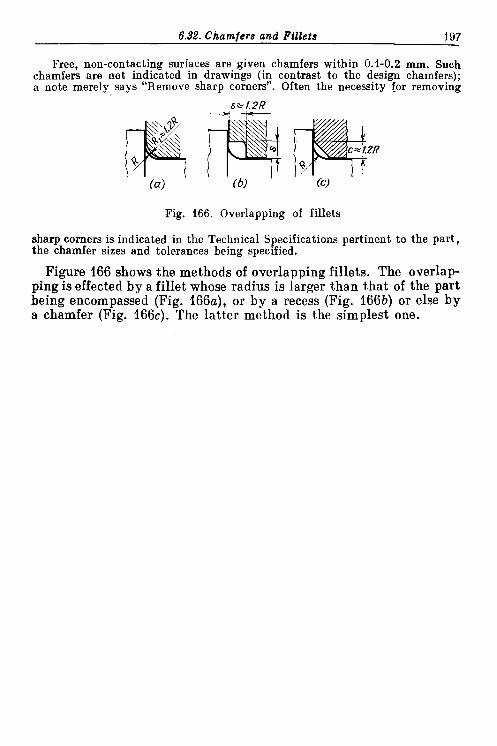
6.32. Chamfers and Fillets 197
Free, non-contacting surfaces are given chamfers within 0.1-0.2 mm. Such chamfers are not indicated in drawings (in contrast to the design chamfers); a note merely says "Remove sharp corners". Often the necessity for removing
Fig. 166. Overlapping of fillets
sharp corners is indicated in the Technical Specifications pertinent to the part, the chamfer sizes and tolerances being specified.
Figure 166 shows the methods of overlapping fillets. The overlap- ping is effected by a fillet whose radius is larger than that of the part being encompassed (Fig. 166a), or by a recess (Fig. 166b) or else by a chamfer (Fig. 1 6 6 ~ ) . The latter method is the simplest one.

Table 8
Chamfers
Design
wrong I correct Application
Design Purpose 1
wrong I correct Application I Purpose
Q @ joints
Slide bea- rings and other movable con- nec t ions
Gear teeth. Parts working under contact loads
Knurled parts
Press-fitted connections
Press-fitting into sof t-metal parts
To reduce edge pressures
To eliminate load concentra- tion a t edges
To improve appearance
To facilitate pressf itting
To revent metal Born rising around hole edges

Application Design
wrong I correct
Threaded :onnect ions
Design
wrong I correct
Table 8 (continued)
Purpose
To facilitate screwing of nuts and threaded rods
To facilitate use of spanners
To form an annular bearing surface (with diameter D). To prevent point contact on bearing surface

Table 9
Fillets
Design U Design Application Application
wrong I correct wrong I correct
local variations
sition of metal

Table 9 (continued)
Design Design Application Purpose I I Application
Lwrong; I correct I correct
ion. To facili-

Table 9 (continued)
Design
wrong 1 correct
Design Design I Application Pllrpose wrong I correct I- wrong 1 correct
To enhance

Index Accuracy of parts alignment, 179 Elasticity, effect on load distribution, Alignment of flanges, 105 164 Axial fixing of parts, 172 Elimination,
of adjustments, 124 of deformations due to tightening,
Bending, elimination and reduction of, 137
143 of local weak spots, 186
Butt-jointing on intersecting surfaces, Equistrength, 152 , 177
Fillets. 196 Cambering, 161 Chamfers, 196 Combining design functions, 150 Compactness of design, 146 Compensators, 129 Com~osite constructions. 189 Con<ection(s),
centring, 79 conical flange, 113 design rules for, 80 glued, 78 loaded. 12
~ i t t i n g to several surfaces, 170 Fit(s),
conical, 75 drive, 37 press, 37 selection of, 46
Interchangeability of rapidly wearing parts, 178
Methods of c b n t r o ~ l i n ~ preloads, 32 Mounting surfaces, 175
pressed, desi n of, 67 pressed, wi& electro-deposited p r e s ~ $ ~ i ~ ~ o l i n g of parts, 64
coatings, 65 ~ress-fitted. 37 with heating of parts, 64 screwed, centring in, 92 serrated, 77 Rationalization of power schemes, strength of, 38 126 three-flange, 111 Relaxation, 25 tightened, 7 Relief of precision mechanisms, 181 unloaded, 7
Control of direction, 174 Self-alignment, 157 Shoulders, 194 Cou ling of partsof different hardness, Strengthening of deformable areas, 188 I &
~o;Jing(s), floating cross-sliding. 136 Tightening up on two surfaces, 171 Torsion bars. 133
Design, compactness of, 146 Unification, of equally strong parts, 152 of design elements, 116 general principles of. 116 of ~ a r t s . 119 zf pressed corinections, 67 uniform loading of supports, 156 of screwed connections, 94 Unitization, principles of, 121

TO T H E READER
Mir Publishers welcome your comments on the content, trans- lation, and design of the book.
We would also be pleased to receive any suggestions you care to make about our future publications.
Our address is: USSR, 129820, Moscow, 1-110, GSP, Pervy Rizhsky Pereulok, 2,
Mir Publishers
Printed in the Union of Soviet Socialist Republics

OTHER BOOKS FOR YOUR LIBRARY
MECHANISMS IN MODERN ENGINEERING DESIGN. BY I . ARTOBOLEVSKY
A handbook in six volumes for engineers, designers, and inventors on the mechanisms used in modern engineering design. Each mechan- ism is represented by a diagram of its working principle, with a concise description, and classified by a scheme proposed and deve- loped by the author.
Vol. I. Lever Mechanisms. Illustrates and describes 912 lever mechanism. Contents. Elements. Simple lever mechanisms. Jointed lever mechanisms.
Vol. 11. Lever Mechanisms (in two parts). Illustrates and describes 1376 lever mechanisms. Contents. Link-gear mechanisms. Slider-crank mechanisms. Lever-cam mechanisms. Gear-lever mechanisms. Lever-ratchet mecha- nisms. Flexible-link lever mechanisms. Elastic-link lever mechan- isms. Wedge-lever mechanisms. Lever-screw mechanisms.
Vol. 111. Gear Mechanisms. Illustrates and describes 689 toothed, friction and cam mechanisms. Contents. Simple gear mechanisms. Lever-gear mechanisms. Pin- gear mechanisms. Cam-gear mechanisms. Ratchet-gear mechanisms. Worm-gear mechanisms. Complex gear mechanisms.

MACHINE TOOLS. BY IV. CHERNOV
A textbook for technical colleges and apprentice engineers on the standard parts and mechanisms, electrical and hydraulic equipment of machine tools, the equipment of automatic transfer lines, and N/C machine tools.
Contents. Introduction to machine tools. Standard parts and mechan- isms. Electrical equipment. Hydraulic equipment. Automatic (Numerical) control. Standard lathes. Turret lathes. Backing-off lathes. Multihead machines. Semiautomatic and automatic lathes. Drilling machines Boring machines. Milling machines. Dividing heads. Principles of tracer milling machines. Thread-cutting machi- ines. Shapers and planers. Broaching machines. Grinders. Lapping machines. Gear-cutting machines. Machine tools built from standard units. Automatic transfer lines. Electrosparking, ultrasonic and other machines, NIC machine tools. Modernization. Installation. Testing, maintenance and repairs of machine tools.
MACHINE ELEMENTS. BY V. DOBROVOLSKY et at.-
A textbook for university mechanical engineering faculties. Contains rules, methods and standards for designing the elements on the basis of their working conditions. Acquaints the reader with the design of individual elements, and the various forms of assembly and drive used in modern engineering. Contents. Part I. Fundamentals of designing machine elements. Criteria of operating capacity and calculation of machine elements. Selection of material. Standardization. Production soundness.
Part I I . Joints. Types of joint. Riveted joints. Welded joints. Joints formed by interference fits. Threaded joints. Cottered fastenings. Keyed, splined and keyless joints.
Part I I I . Power transmission. Types of drive. Friction drives. Belting. Gearing. Helical and hypoid gears. Worm gears. Globoidal gears. Reduction gears. Chain drives. Power screws.
Part IV. Shafts, bearings and couplings. Shafts and axles. Sliding- contact bearings. Rolling-contact bearings. Couplings and clutches.
Part V . Springs and fram,es. Springs. Machine frames.

ENGINEERING TECHNIQUES FOR ANALYZING STRENGTH AND RIGIDITY. BY G. GLUSHKOV
A monograph on the theory of moments developed by the author, and its application to engineering design problems on the strength, rigidity, and stability of beams and columns. The approximate (and occasionally exact) solutions obtained can be employed to analyze loads of all kinds. The method is also applicable to various-non-linear problems.
Contents. Fundamentals of the theory of moments. Application of the theory. Fundamentals of the moment-operational techniques.
FORMULAS FOR DESIGNING COMPLEX FRAMES. BY G. GLUSHKOV I . EGOROV, V . ERMOLOV.
A collection of formulas for calculating the moments and reactions at supports and joints of complex frames and arches under various loads.
Contents. Frames with stepped suppors (16 variants): Multispan and multistorey frames (49 variants). Arches (14 variants)..Force diagrams and load factors (117 variants).
Appendices. Examples of analyses. Formulas for calculating shearing forces, bending moments, and the angles of rotation and sag of simple beams (117 variants).